EP1912290A1 - Electric connector housing - Google Patents
Electric connector housing Download PDFInfo
- Publication number
- EP1912290A1 EP1912290A1 EP06747183A EP06747183A EP1912290A1 EP 1912290 A1 EP1912290 A1 EP 1912290A1 EP 06747183 A EP06747183 A EP 06747183A EP 06747183 A EP06747183 A EP 06747183A EP 1912290 A1 EP1912290 A1 EP 1912290A1
- Authority
- EP
- European Patent Office
- Prior art keywords
- holder
- connector housing
- electric connector
- view
- cover
- Prior art date
- Legal status (The legal status is an assumption and is not a legal conclusion. Google has not performed a legal analysis and makes no representation as to the accuracy of the status listed.)
- Granted
Links
Images





Classifications
-
- H—ELECTRICITY
- H01—ELECTRIC ELEMENTS
- H01R—ELECTRICALLY-CONDUCTIVE CONNECTIONS; STRUCTURAL ASSOCIATIONS OF A PLURALITY OF MUTUALLY-INSULATED ELECTRICAL CONNECTING ELEMENTS; COUPLING DEVICES; CURRENT COLLECTORS
- H01R13/00—Details of coupling devices of the kinds covered by groups H01R12/70 or H01R24/00 - H01R33/00
- H01R13/46—Bases; Cases
- H01R13/516—Means for holding or embracing insulating body, e.g. casing, hoods
-
- H—ELECTRICITY
- H01—ELECTRIC ELEMENTS
- H01R—ELECTRICALLY-CONDUCTIVE CONNECTIONS; STRUCTURAL ASSOCIATIONS OF A PLURALITY OF MUTUALLY-INSULATED ELECTRICAL CONNECTING ELEMENTS; COUPLING DEVICES; CURRENT COLLECTORS
- H01R13/00—Details of coupling devices of the kinds covered by groups H01R12/70 or H01R24/00 - H01R33/00
- H01R13/40—Securing contact members in or to a base or case; Insulating of contact members
- H01R13/42—Securing in a demountable manner
-
- H—ELECTRICITY
- H01—ELECTRIC ELEMENTS
- H01R—ELECTRICALLY-CONDUCTIVE CONNECTIONS; STRUCTURAL ASSOCIATIONS OF A PLURALITY OF MUTUALLY-INSULATED ELECTRICAL CONNECTING ELEMENTS; COUPLING DEVICES; CURRENT COLLECTORS
- H01R13/00—Details of coupling devices of the kinds covered by groups H01R12/70 or H01R24/00 - H01R33/00
- H01R13/40—Securing contact members in or to a base or case; Insulating of contact members
- H01R13/42—Securing in a demountable manner
- H01R13/436—Securing a plurality of contact members by one locking piece or operation
- H01R13/4361—Insertion of locking piece perpendicular to direction of contact insertion
-
- H—ELECTRICITY
- H01—ELECTRIC ELEMENTS
- H01R—ELECTRICALLY-CONDUCTIVE CONNECTIONS; STRUCTURAL ASSOCIATIONS OF A PLURALITY OF MUTUALLY-INSULATED ELECTRICAL CONNECTING ELEMENTS; COUPLING DEVICES; CURRENT COLLECTORS
- H01R13/00—Details of coupling devices of the kinds covered by groups H01R12/70 or H01R24/00 - H01R33/00
- H01R13/46—Bases; Cases
- H01R13/502—Bases; Cases composed of different pieces
-
- H—ELECTRICITY
- H01—ELECTRIC ELEMENTS
- H01R—ELECTRICALLY-CONDUCTIVE CONNECTIONS; STRUCTURAL ASSOCIATIONS OF A PLURALITY OF MUTUALLY-INSULATED ELECTRICAL CONNECTING ELEMENTS; COUPLING DEVICES; CURRENT COLLECTORS
- H01R13/00—Details of coupling devices of the kinds covered by groups H01R12/70 or H01R24/00 - H01R33/00
- H01R13/46—Bases; Cases
- H01R13/514—Bases; Cases composed as a modular blocks or assembly, i.e. composed of co-operating parts provided with contact members or holding contact members between them
-
- H—ELECTRICITY
- H01—ELECTRIC ELEMENTS
- H01R—ELECTRICALLY-CONDUCTIVE CONNECTIONS; STRUCTURAL ASSOCIATIONS OF A PLURALITY OF MUTUALLY-INSULATED ELECTRICAL CONNECTING ELEMENTS; COUPLING DEVICES; CURRENT COLLECTORS
- H01R13/00—Details of coupling devices of the kinds covered by groups H01R12/70 or H01R24/00 - H01R33/00
- H01R13/62—Means for facilitating engagement or disengagement of coupling parts or for holding them in engagement
- H01R13/627—Snap or like fastening
- H01R13/6271—Latching means integral with the housing
- H01R13/6272—Latching means integral with the housing comprising a single latching arm
Definitions
- the present invention relates to an electric connector housing for accommodating therein connection terminals of small size.
- connection terminals for use in an electrical circuits of automobiles have become smaller and smaller.
- connection terminals installed within an electric connector housing are retained therein by means of resilient stopping lances provided within the electric connector housing.
- Japanese Patent Document 1 there is disclosed a known electric connector housing, in which a rear holder 1 having formed therein stopping lances 2 is fitted to a rear portion of a housing as shown in Fig. 43 .
- Patent Document 1 Japanese Patent Kokai 2004-39535
- the present invention has for its object to provide an electric connector housing, in which the above mentioned drawbacks of the known electric connector housings can be removed and connection terminals of small size can be fixed in position with a large engaging force.
- an electric connector housing comprises an assembly of a holder having a plurality of grooves for accommodating therein respective connection terminals and a cover for covering said grooves of the holder, wherein moving preventing means for preventing said connection terminals from moving in forward and backward directions are provided in either one or both of said holder and cover.
- connection terminals can be retained within the housing with a sufficiently large retaining force.
- Fig. 1 is a plan view showing a connection terminal to be used
- Fig. 2 is a longitudinal cross sectional view illustrating the connection terminal a part of which is cut out
- Fig. 3 is a lateral cross sectional view cut along a line A-A in Fig. 1
- a contact portion 12 having a rectangular tube shape, and at a rear portion continued from the front portion through an intermediate portion 13 an electric wire 15 is connected by means of a clamp portion 14.
- a cut-out portion 16 is formed at a front end of a connection terminal 11 having a rectangular tube shape, and at a rear portion continued from the front portion through an intermediate portion 13 an electric wire 15 is connected by means of a clamp portion 14. Furthermore, in a bottom portion of the contact portion 12, there is formed a cut-out portion 16.
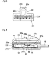
- Fig. 4 is a plan view showing the electric connector housing of the first embodiment 1
- Fig. 5 is a front view thereof
- Fig. 6 is a longitudinal cross sectional view showing a condition in which the connection terminal 11 is installed within the electric connector housing.
- the electric connector housing is composed of an assembly of a lower holder 21 and an upper cover 22 provided on the lower holder.
- the connection terminals 11 are fit into respective grooves 21a formed in an upper surface of the holder 21.
- the upper cover 22 is arranged on the holder 21 in such a fashion that the grooves 21a are covered with the upper cover 22.
- a resilient bridge portion 22a which functions to lock a cooperating electric connector housing to the relevant electric connector housing, a locking projection 22b and a push portion 22c for disengaging the locking between the relevant electric connector housing and the cooperating electric connector housing.
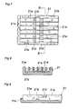
- Fig. 7 is a plan view showing the holder 21
- Fig. 8 is a lateral cross sectional view cut along a line B-B in Fig. 7
- Fig. 9 is a longitudinal cross sectional view depicting the holder 21.
- an upper surface of the holder 21 there are formed a plurality of the grooves 21a extending in the longitudinal direction, and in the bottom surface of each groove 21a there is formed an engaging protrusion 21b which is inserted into the cut-out portion 16 of the connection terminal 11.
- a front wall portion 21c is provided at a front end portion of the grooves 21a, said front wall portion serving to prevent undesired forward movement of the connection terminals 11 and to guide cooperating connection terminals into the grooves 21a.
- each of the grooves 21a there are provided projections 21d which are engaged with the intermediate portion 13 of the connection terminal 11 to prevent undesired up and down movement of the connection terminals 11 within the grooves 21a.
- projections 21d which are engaged with the intermediate portion 13 of the connection terminal 11 to prevent undesired up and down movement of the connection terminals 11 within the grooves 21a.
- locking depressions 21e At four corners of the holder 21 there are further formed locking depressions 21e.
- Fig. 10 is a lateral cross sectional view and Fig. 11 is a longitudinal cross sectional view showing a condition in which the connection terminal 11 is installed in the holder 21. Any undesired forward movement of the connection terminal 11 is prevented by the engaging protrusion 21b and front wall portion 21c. Any undesired up and down movement of the connection terminal 11 is prevented by the projections 21d.
- Fig. 12 is a bottom view and Fig. 13 is a longitudinal cross sectional view showing the upper cover 22.
- a plan view of the upper cover 22 is identical with that shown in Fig. 4 .
- the upper cover 22 has formed therein a common engaging projection 22d which is engaged with the rear ends of the contact portions 12 of the connection terminals 11 to prevent undesired backward movement of the connection terminals.
- a front wall portion 22e of the upper cover 22 there are formed guide openings 22f for receiving cooperating connection terminals 11.
- locking claws 22g are formed which are engaged with the locking depressions 21e of the holder 21.
- the upper cover 22 is placed on the holder 21 and the locking claws 22g are clicked into the locking depressions 21e. Then, the holder 21 and upper cover 22 are coupled with each other as shown in Figs. 5 and 6 .
- connection terminal 11 can be firmly prevented from moving in the forward direction as well as in the up and down direction by means of the holder 21 and upper cover 22.
- the thus assembled electric connector housing may be combined with a cooperating electric connector housing to constitute an electric connector.
- Fig. 14 is a front view showing the second embodiment 2 of the electric connector housing according to the invention and Fig. 15 is a longitudinal cross sectional view depicting a condition in which a connection terminal 11 is installed within the housing.
- a plan view of the housing of this embodiment is identical with that shown in Fig. 4 .
- connection terminal accommodating portions each of which is similar to that of the first embodiment 1 are placed one on the other.
- On a holder 21 which is identical with the holder 21 of the first embodiment 1 two intermediate holders 31 are stacked, and on the upper intermediate holder 31 is placed an upper cover 22 which is identical with the upper cover 22 of the first embodiment 1.
- the connection terminals 11 are installed in the holder 21 and two intermediate holders 31.
- Fig. 16 is a longitudinal cross sectional view illustrating the intermediate holder 31.
- a plan view of this intermediate holder 31 is identical with the plan view of the holder 21 shown in Fig. 7
- a bottom view of the intermediate holder 31 is identical with the bottom view of the upper cover 22 shown in Fig. 12 .
- On the bottom surface of the intermediate holder 31 there are provided an engaging projection 31a, a front wall portion 31b, guide openings 31c and locking claws 31d at four corners.
- On the top surface of the intermediate holder 31 there are provided grooves 31e, engaging protrusions 31f for preventing the forward movement of the connection terminals, a front wall portion 31g, projections 31h for preventing the up and down movement of the connection terminals and locking depressions 31i at four corners.
- connection terminals 11 are installed in the grooves 21a of the holder 21 such that the connection terminals 11 are held in position by means of the engaging protrusions 21b, engaging projections 21d and front wall portion 21c. Then, the intermediate holders 31 in which the connection terminals 11 are installed in position are successively stacked on the holder 21, while the locking claws 31d of the lower intermediate holder 31 are inserted into the locking depressions 21e of the holder 21 and the locking claws 31i of the upper intermediate holder 31 are clicked into the locking depressions 31i of the lower intermediate holder 31.
- the upper cover 22 is placed on the upper intermediate holder 31, while the locking claws 22g of the upper cover 22 are clicked into the locking depressions 31i of the upper intermediated holder 31 to fix the connection terminals 11 in position by means of the engaging projection 22d of the upper cover 22.
- connection terminals 11 installed within the holder 21 and two intermediate holders 31 can be fixed in position and the connection terminals 11 are effectively prevented from moving in the forward and backward direction as well as in the up and down direction.
- Fig. 18 is a front view and Fig. 19 is a longitudinal cross sectional view showing the electric connector housing of the third embodiment 3.
- a plan view of the electric connector housing of this embodiment 3 is identical with that shown in Fig. 4 .
- On an upper surface of an intermediate holder 41 is placed an upper cover 22 and on a lower surface of the intermediate holder 41 is placed a lower cover 42.
- Figs. 20 and 21 are a lateral cross sectional view and a longitudinal cross sectional view illustrating the intermediate holder 41.
- a plan view and a bottom view of this intermediate holder 41 are identical with that shown in Fig. 7 . That is to say, the upper and lower surfaces of the intermediate holder 41 have a symmetrical configuration.
- On each of the upper and lower surfaces of the intermediate holder 41 there are formed a plurality of longitudinal grooves 41a, engaging protrusions 41b, a front wall portion 41c, projections 41d for restricting the forward movement of the connection terminals, and four locking recesses 41e at four corners like as the holder 21.
- the connection terminals 11 are arranged in the grooves 41a formed in the upper and lower surfaces of the intermediate holder 41, said connection terminals being aligned symmetrically viewed in the up and down direction.
- Fig. 22 is a longitudinal cross sectional view depicting the lower cover 42.
- a plan view of the lower cover 42 is identical with that shown in Fig. 12 .
- the lower cover 42 has a substantially identical structure with that of the of the upper cover 22 from which the resilient bridge portion 22a is removed.
- the lower cover 42 has formed therein an engaging projection 42a, a front wall portion 42b, guide openings 42c and locking claws 42d.
- connection terminals 11 After installing the connection terminals 11 within the intermediate holder 41, the lower and upper surfaces of the intermediate holder are covered with the lower cover 42 and upper cover 22, respectively, and locking claws are clicked into the locking recesses to assemble these three parts.
- connection terminals 11 In this condition, undesired forward movement of the connection terminals 11 is prevented by the intermediate holder 41 and undesired backward movement of the connection terminals 11 is prevented by the upper and lower covers 22 and 42.
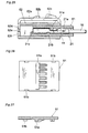
- Figs. 23, 24 and 25 are a plan view, a front view and a longitudinal cross sectional view, respectively showing the electric connector housing of the present embodiment 4.
- a plurality of connection terminals 11 are installed in a plurality of grooves 21a of a holder 21 which is similar to that of the first embodiment 1.
- the grooves 21a are covered with an intermediate upper cover 51.
- An assembly of the holder 21 and intermediate upper cover 51 is covered with an outer cover 52.
- a front wall portion 21c has no guide opening as compared with the holder 21 of the first embodiment 1.
- Figs. 26 and 27 are a bottom view and a longitudinal cross sectional view, respectively illustrating the intermediate upper cover 51.
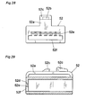
- Figs. 28 and 29 are a front view and a longitudinal cross sectional view, respectively showing the outer cover 52.
- a plan view of the outer cover 52 is identical with that shown in Fig. 23 .
- the outer cover 52 has a vacant space, and a resilient bridge portion 52a, locking projection 52b and a push portion 52c are formed on an upper surface.
- a front wall portion 52d of the outer cover 52 has formed therein guide openings 52e and a fitting hole 52f into which a front end of the holder 21 is inserted.
- the holder 21 After placing the connection terminals 11 on the upper surface of the holder 21, the holder 21 is covered with the intermediate upper cover 51. Then, an assembly of the holder 21 and intermediate upper cover 51 is inserted into the outer cover 52 as depicted in Fig. 30 to obtain the electric connector housing shown in Fig. 25 .
- locking members for locking the holder 21 and intermediate upper cover 51 with the outer cover 52 are provided on an inner surface of the outer cover 52.
- connection terminals 11 are prevented from moving in forward and backward direction by means of the holder 21 and at the same time the backward movement of the connection terminals 11 is inhibited by the intermediate upper cover 51.
- the outer cover 52 since the outer cover 52 is provided, a much stronger structure can be realized as compared with the embodiments 1-3.
- Figs. 31 and 32 are a front view and a longitudinal cross sectional view, respectively illustrating the electric connector housing of the embodiment 5.
- a plan view of the electric connector housing of this embodiment 5 is identical with that shown in Fig. 23 .
- a plurality of connection terminals 11 are installed in a plurality of upper and lower grooves 41a of an intermediate holder 41 which is similar to that of the embodiment 3.
- the upper and lower grooves 41a are covered with an intermediate upper cover 51 in the embodiment 4.
- Furthermore an assembly of the intermediate holder 41 and intermediate upper cover 51 is covered with an outer cover 61.
- Figs. 33 and 34 are a front view and a longitudinal cross sectional view, respectively showing the outer cover 61.
- the outer cover 61 has a vacant space, and a resilient bridge portion 61a, locking projection 61b and a push portion 61c are formed on an upper surface.
- a front wall portion 61d of the outer cover 61 has formed therein guide openings 61e and a fitting hole 61f into which a front end of the intermediate holder 41 is inserted.
- the intermediate holder 41 After fixing the connection terminals 11 into the upper and lower grooves 41a of the intermediate holder 41, the intermediate holder 41 is covered with the intermediate upper cover 51. Then, an assembly of the intermediate holder 41 and intermediate upper cover 51 is inserted into the outer cover 61 as shown in Fig. 35 to obtain the electric connector housing shown in Fig. 32 .
- connection terminals 11 are prevented from moving in forward and backward direction by means of the intermediate holder 41, and moreover the backward movement of the connection terminals 11 is inhibited by the intermediate upper cover 51.
- Figs. 36 and 37 are a front view and a longitudinal cross sectional view, respectively showing the electric connector housing of the sixth embodiment 6.
- a plan view of the electric connector housing of this embodiment 6 is identical with that shown in Fig. 23 .
- Two intermediate holders 71 are stacked on a holder 21 which is identical with that of the first embodiment 1, and an intermediate upper cover 51 which is identical with that of the fourth embodiment 4 is stacked on the upper intermediate holder 71.
- a plurality of connection terminals 11 are installed within the holder 21 and intermediate holders 71, and an assembly of the holder 21, intermediate holders 71 and intermediate upper cover 51 is covered with an outer cover 72.
- Figs. 38 and 39 are a bottom view and a longitudinal cross sectional view, respectively showing the intermediate holder 71.
- a plan view of this intermediate holder 71 is identical with that shown in Fig. 7 .
- On an upper surface of the intermediate holder 71 there are formed a plurality of grooves 71a, and in each of the grooves 71a there is formed an engaging protrusion 71b.
- the intermediate holder 71 has further formed therein a front wall portion 71c, projections 71d for inhibiting the up and down movement of the connection terminals and four locking recesses 71e at four corners.
- Figs. 40 and 41 are a front view and a longitudinal cross sectional view, respectively depicting the outer cover 72.
- the outer cover 72 includes a resilient bridge portion 72a, a locking projection 72b and a push portion 72c.
- a front wall portion 72d of the outer cover 72 has formed therein guide openings 72e and fitting holes 72f into which front ends of the holder 21 and intermediate holders 71 are inserted.
- connection terminals 11 are prevented from moving in forward and backward directions by means of the holder 21 and intermediate holder 71, and the backward movement of the connection terminals 11 is inhibited by the intermediate upper cover 51.
- the electric connector housing is formed as a receipt type, but the present invention may be equally applied the electric connector housing of insertion type.
Landscapes
- Connector Housings Or Holding Contact Members (AREA)
Abstract
Description
- The present invention relates to an electric connector housing for accommodating therein connection terminals of small size.
- For instance, connection terminals for use in an electrical circuits of automobiles have become smaller and smaller.
- In general, connection terminals installed within an electric connector housing are retained therein by means of resilient stopping lances provided within the electric connector housing.
- In accordance with a miniaturization of connection terminals, it is difficult to form stopping lances within the electric connector housing by injection mold. Known stopping lances could have a small engaging force.
- In order to mitigate this problem, in a following Japanese Patent Document 1 there is disclosed a known electric connector housing, in which a rear holder 1 having formed therein
stopping lances 2 is fitted to a rear portion of a housing as shown inFig. 43 . - However, even in such a structure, it is still difficult to form stopping lances of small size, and a sufficiently large engaging force for retaining the connection terminals within the housing.
- Patent Document 1:
Japanese Patent Kokai 2004-39535 - The present invention has for its object to provide an electric connector housing, in which the above mentioned drawbacks of the known electric connector housings can be removed and connection terminals of small size can be fixed in position with a large engaging force.
- In order to attain the above object, according to the invention, an electric connector housing comprises an assembly of a holder having a plurality of grooves for accommodating therein respective connection terminals and a cover for covering said grooves of the holder, wherein moving preventing means for preventing said connection terminals from moving in forward and backward directions are provided in either one or both of said holder and cover.
- In the electric connector housing according to the invention, even though a size of the connection terminals becomes small, the connection terminals can be retained within the housing with a sufficiently large retaining force.
-
-
Fig. 1 is a plan view showing a connection terminal; -
Fig. 2 is a longitudinal cross sectional view cut a portion of the connection terminal; -
Fig. 3 is a lateral cross sectional view cut along a line A-A inFig. 2 ; -
Fig. 4 is a plan view illustrating a first embodiment 1 of the electric connector housing according to the invention; -
Fig. 5 is a front view of the electric connector housing of the first embodiment 1; -
Fig. 6 is a longitudinal cross sectional view depicting condition in which a connection terminal is installed in the housing; -
Fig. 7 is a plan view representing a holder; -
Fig. 8 is a lateral cross sectional view cut along a line B-B inFig. 7 ; -
Fig. 9 is a longitudinal cross sectional view illustrating the holder; -
Fig. 10 is a lateral cross sectional view showing a condition in which the connection terminal is fit within the holder; -
Fig. 11 is a longitudinal cross sectional view of the holder having the connection terminal installed therein; -
Fig. 12 is a bottom view depicting an upper cover; -
Fig. 13 is a longitudinal cross sectional view of the cover; -
Fig. 14 is a front view illustrating asecond embodiment 2 of the electric connector housing according to the invention; -
Fig. 15 is a longitudinal cross sectional view depicting a condition in which a connection terminal is installed within the housing; -
Fig. 16 is a longitudinal cross sectional view showing an intermediate holder; -
Fig. 17 is an explanatory view representing an assembling step; -
Fig. 18 is a front view depicting a third embodiment 3 of the electric connector housing according to the present invention; -
Fig. 19 is a longitudinal cross sectional view showing the electric connector housing of the third embodiment 3; -
Fig. 20 is a lateral cross sectional view showing an intermediate holder; -
Fig. 21 is a longitudinal cross sectional view of the intermediate holder; -
Fig. 22 is a longitudinal cross sectional view illustrating a lower cover; -
Fig. 23 is a plan view depicting a fourth embodiment 4 of the electric connector housing according to the invention; -
Fig. 24 is a front view of the electric connector housing of the fourth embodiment 4; -
Fig. 25 is a longitudinal cross sectional view of the electric connector housing; -
Fig. 26 is a bottom view showing an upper intermediate cover; -
Fig. 27 is a longitudinal cross sectional view of the upper intermediate cover; -
Fig. 28 is a front view illustrating an outer cover; -
Fig. 29 is a longitudinal cross sectional view of the outer cover; -
Fig. 30 is a longitudinal cross sectional view showing an assembling step; -
Fig. 31 is a front view depicting a fifth embodiment 5 of the electric connector housing according to the invention; -
Fig. 32 is a longitudinal cross sectional view of the electric connector housing of the embodiment 5; -
Fig. 33 is a front view showing an outer cover; -
Fig. 34 is a longitudinal cross sectional view of the outer cover; -
Fig. 35 is a longitudinal cross sectional view depicting an assembling step; -
Fig. 36 is a front view showing a sixth embodiment 6 of the electric connector housing according to the invention; -
Fig. 37 is a longitudinal cross sectional view of the electric connector housing of the sixth embodiment 6; -
Fig. 38 is a bottom view depicting an intermediate holder; -
Fig. 39 is a longitudinal cross sectional view of the intermediate holder; -
Fig. 40 is a front view depicting an outer cover; -
Fig. 41 is a longitudinal cross sectional view of the outer cover; -
Fig. 42 is a longitudinal cross sectional view showing an assembling step; and -
Fig. 43 is a perspective view illustrating a known electric connector housing. -
- 11
- connection terminal
- 12
- contact portion
- 13
- intermediate portion
- 14
- clamp portion
- 15
- electric wire
- 16
- cut-out portion
- 21
- holder
- 22
- upper cover
- 31, 41, 71
- intermediate holder
- 42
- lower cover
- 51
- intermediate upper cover
- 52, 61, 72
- outer cover
- Now the present invention will be explained in detail with reference to the embodiments of the invention shown in the drawings.
-
Fig. 1 is a plan view showing a connection terminal to be used,Fig. 2 is a longitudinal cross sectional view illustrating the connection terminal a part of which is cut out, andFig. 3 is a lateral cross sectional view cut along a line A-A inFig. 1 . At a front end of aconnection terminal 11 there is provided acontact portion 12 having a rectangular tube shape, and at a rear portion continued from the front portion through anintermediate portion 13 anelectric wire 15 is connected by means of aclamp portion 14. Furthermore, in a bottom portion of thecontact portion 12, there is formed a cut-outportion 16. -
Fig. 4 is a plan view showing the electric connector housing of the first embodiment 1,Fig. 5 is a front view thereof andFig. 6 is a longitudinal cross sectional view showing a condition in which theconnection terminal 11 is installed within the electric connector housing. The electric connector housing is composed of an assembly of alower holder 21 and anupper cover 22 provided on the lower holder. Theconnection terminals 11 are fit intorespective grooves 21a formed in an upper surface of theholder 21. Theupper cover 22 is arranged on theholder 21 in such a fashion that thegrooves 21a are covered with theupper cover 22. On an upper surface of theupper cover 22 there are provided aresilient bridge portion 22a which functions to lock a cooperating electric connector housing to the relevant electric connector housing, a lockingprojection 22b and apush portion 22c for disengaging the locking between the relevant electric connector housing and the cooperating electric connector housing. -
Fig. 7 is a plan view showing theholder 21,Fig. 8 is a lateral cross sectional view cut along a line B-B inFig. 7 and Fig. 9 is a longitudinal cross sectional view depicting theholder 21. In an upper surface of theholder 21, there are formed a plurality of thegrooves 21a extending in the longitudinal direction, and in the bottom surface of eachgroove 21a there is formed an engagingprotrusion 21b which is inserted into the cut-outportion 16 of theconnection terminal 11. Furthermore, afront wall portion 21c is provided at a front end portion of thegrooves 21a, said front wall portion serving to prevent undesired forward movement of theconnection terminals 11 and to guide cooperating connection terminals into thegrooves 21a. At both sides of a middle portion of each of thegrooves 21a there are providedprojections 21d which are engaged with theintermediate portion 13 of theconnection terminal 11 to prevent undesired up and down movement of theconnection terminals 11 within thegrooves 21a. At four corners of theholder 21 there are further formed lockingdepressions 21e. -
Fig. 10 is a lateral cross sectional view andFig. 11 is a longitudinal cross sectional view showing a condition in which theconnection terminal 11 is installed in theholder 21. Any undesired forward movement of theconnection terminal 11 is prevented by the engagingprotrusion 21b andfront wall portion 21c. Any undesired up and down movement of theconnection terminal 11 is prevented by theprojections 21d. -
Fig. 12 is a bottom view andFig. 13 is a longitudinal cross sectional view showing theupper cover 22. A plan view of theupper cover 22 is identical with that shown inFig. 4 . Theupper cover 22 has formed therein a commonengaging projection 22d which is engaged with the rear ends of thecontact portions 12 of theconnection terminals 11 to prevent undesired backward movement of the connection terminals. In afront wall portion 22e of theupper cover 22 there are formedguide openings 22f for receiving cooperatingconnection terminals 11. Moreover, at four corners of theupper cover 22 there are formed lockingclaws 22g which are engaged with the lockingdepressions 21e of theholder 21. - As illustrated in
Figs. 10 and 11 , after installing theconnection terminals 11 within theholder 21, theupper cover 22 is placed on theholder 21 and the lockingclaws 22g are clicked into the lockingdepressions 21e. Then, theholder 21 andupper cover 22 are coupled with each other as shown inFigs. 5 and 6 . - In this condition, the
connection terminal 11 can be firmly prevented from moving in the forward direction as well as in the up and down direction by means of theholder 21 andupper cover 22. The thus assembled electric connector housing may be combined with a cooperating electric connector housing to constitute an electric connector. -
Fig. 14 is a front view showing thesecond embodiment 2 of the electric connector housing according to the invention andFig. 15 is a longitudinal cross sectional view depicting a condition in which aconnection terminal 11 is installed within the housing. A plan view of the housing of this embodiment is identical with that shown inFig. 4 . In thisembodiment 2, connection terminal accommodating portions each of which is similar to that of the first embodiment 1 are placed one on the other. On aholder 21 which is identical with theholder 21 of the first embodiment 1, twointermediate holders 31 are stacked, and on the upperintermediate holder 31 is placed anupper cover 22 which is identical with theupper cover 22 of the first embodiment 1. Theconnection terminals 11 are installed in theholder 21 and twointermediate holders 31. -
Fig. 16 is a longitudinal cross sectional view illustrating theintermediate holder 31. A plan view of thisintermediate holder 31 is identical with the plan view of theholder 21 shown inFig. 7 , and a bottom view of theintermediate holder 31 is identical with the bottom view of theupper cover 22 shown inFig. 12 . On the bottom surface of theintermediate holder 31 there are provided an engagingprojection 31a, afront wall portion 31b, guideopenings 31c and lockingclaws 31d at four corners. On the top surface of theintermediate holder 31 there are providedgrooves 31e, engagingprotrusions 31f for preventing the forward movement of the connection terminals, afront wall portion 31g,projections 31h for preventing the up and down movement of the connection terminals and lockingdepressions 31i at four corners. - As depicted in
Fig. 17 , in thesecond embodiment 2, theconnection terminals 11 are installed in thegrooves 21a of theholder 21 such that theconnection terminals 11 are held in position by means of the engagingprotrusions 21b, engagingprojections 21d andfront wall portion 21c. Then, theintermediate holders 31 in which theconnection terminals 11 are installed in position are successively stacked on theholder 21, while the lockingclaws 31d of the lowerintermediate holder 31 are inserted into the lockingdepressions 21e of theholder 21 and the lockingclaws 31i of the upperintermediate holder 31 are clicked into the lockingdepressions 31i of the lowerintermediate holder 31. - Next, the
upper cover 22 is placed on the upperintermediate holder 31, while the lockingclaws 22g of theupper cover 22 are clicked into the lockingdepressions 31i of the upper intermediatedholder 31 to fix theconnection terminals 11 in position by means of the engagingprojection 22d of theupper cover 22. - In this manner, all the
connection terminals 11 installed within theholder 21 and twointermediate holders 31 can be fixed in position and theconnection terminals 11 are effectively prevented from moving in the forward and backward direction as well as in the up and down direction. -
Fig. 18 is a front view andFig. 19 is a longitudinal cross sectional view showing the electric connector housing of the third embodiment 3. A plan view of the electric connector housing of this embodiment 3 is identical with that shown inFig. 4 . On an upper surface of anintermediate holder 41 is placed anupper cover 22 and on a lower surface of theintermediate holder 41 is placed alower cover 42. -
Figs. 20 and 21 are a lateral cross sectional view and a longitudinal cross sectional view illustrating theintermediate holder 41. A plan view and a bottom view of thisintermediate holder 41 are identical with that shown inFig. 7 . That is to say, the upper and lower surfaces of theintermediate holder 41 have a symmetrical configuration. On each of the upper and lower surfaces of theintermediate holder 41, there are formed a plurality oflongitudinal grooves 41a, engagingprotrusions 41b, afront wall portion 41c,projections 41d for restricting the forward movement of the connection terminals, and fourlocking recesses 41e at four corners like as theholder 21. Theconnection terminals 11 are arranged in thegrooves 41a formed in the upper and lower surfaces of theintermediate holder 41, said connection terminals being aligned symmetrically viewed in the up and down direction. -
Fig. 22 is a longitudinal cross sectional view depicting thelower cover 42. A plan view of thelower cover 42 is identical with that shown inFig. 12 . Thelower cover 42 has a substantially identical structure with that of the of theupper cover 22 from which theresilient bridge portion 22a is removed. Thelower cover 42 has formed therein an engagingprojection 42a, afront wall portion 42b, guideopenings 42c and lockingclaws 42d. - After installing the
connection terminals 11 within theintermediate holder 41, the lower and upper surfaces of the intermediate holder are covered with thelower cover 42 andupper cover 22, respectively, and locking claws are clicked into the locking recesses to assemble these three parts. - In this condition, undesired forward movement of the
connection terminals 11 is prevented by theintermediate holder 41 and undesired backward movement of theconnection terminals 11 is prevented by the upper andlower covers -
Figs. 23, 24 and25 are a plan view, a front view and a longitudinal cross sectional view, respectively showing the electric connector housing of the present embodiment 4. A plurality ofconnection terminals 11 are installed in a plurality ofgrooves 21a of aholder 21 which is similar to that of the first embodiment 1. Thegrooves 21a are covered with an intermediateupper cover 51. An assembly of theholder 21 and intermediateupper cover 51 is covered with anouter cover 52. It should be noted that afront wall portion 21c has no guide opening as compared with theholder 21 of the first embodiment 1. -
Figs. 26 and 27 are a bottom view and a longitudinal cross sectional view, respectively illustrating the intermediateupper cover 51. On the bottom surface of the intermediateupper cover 51 there are formed an engagingprojection 51a and four lockingclaws 51b at four corners, said lockingclaws 51b being clicked into four lockingrecesses 21e formed in theholder 21. -
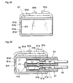
Figs. 28 and 29 are a front view and a longitudinal cross sectional view, respectively showing theouter cover 52. A plan view of theouter cover 52 is identical with that shown inFig. 23 . Theouter cover 52 has a vacant space, and aresilient bridge portion 52a, lockingprojection 52b and apush portion 52c are formed on an upper surface. Afront wall portion 52d of theouter cover 52 has formed therein guideopenings 52e and afitting hole 52f into which a front end of theholder 21 is inserted. - After placing the
connection terminals 11 on the upper surface of theholder 21, theholder 21 is covered with the intermediateupper cover 51. Then, an assembly of theholder 21 and intermediateupper cover 51 is inserted into theouter cover 52 as depicted inFig. 30 to obtain the electric connector housing shown inFig. 25 . Although not shown in the drawings, locking members for locking theholder 21 and intermediateupper cover 51 with theouter cover 52 are provided on an inner surface of theouter cover 52. - In this condition, the
connection terminals 11 are prevented from moving in forward and backward direction by means of theholder 21 and at the same time the backward movement of theconnection terminals 11 is inhibited by the intermediateupper cover 51. In the embodiment 4, since theouter cover 52 is provided, a much stronger structure can be realized as compared with the embodiments 1-3. -
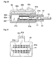
Figs. 31 and32 are a front view and a longitudinal cross sectional view, respectively illustrating the electric connector housing of the embodiment 5. A plan view of the electric connector housing of this embodiment 5 is identical with that shown inFig. 23 . A plurality ofconnection terminals 11 are installed in a plurality of upper andlower grooves 41a of anintermediate holder 41 which is similar to that of the embodiment 3. The upper andlower grooves 41a are covered with an intermediateupper cover 51 in the embodiment 4. Furthermore an assembly of theintermediate holder 41 and intermediateupper cover 51 is covered with anouter cover 61. -
Figs. 33 and34 are a front view and a longitudinal cross sectional view, respectively showing theouter cover 61. Theouter cover 61 has a vacant space, and aresilient bridge portion 61a, lockingprojection 61b and apush portion 61c are formed on an upper surface. Afront wall portion 61d of theouter cover 61 has formed therein guideopenings 61e and afitting hole 61f into which a front end of theintermediate holder 41 is inserted. - After fixing the
connection terminals 11 into the upper andlower grooves 41a of theintermediate holder 41, theintermediate holder 41 is covered with the intermediateupper cover 51. Then, an assembly of theintermediate holder 41 and intermediateupper cover 51 is inserted into theouter cover 61 as shown inFig. 35 to obtain the electric connector housing shown inFig. 32 . - In this condition, the
connection terminals 11 are prevented from moving in forward and backward direction by means of theintermediate holder 41, and moreover the backward movement of theconnection terminals 11 is inhibited by the intermediateupper cover 51. -
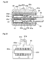
Figs. 36 and 37 are a front view and a longitudinal cross sectional view, respectively showing the electric connector housing of the sixth embodiment 6. A plan view of the electric connector housing of this embodiment 6 is identical with that shown inFig. 23 . Twointermediate holders 71 are stacked on aholder 21 which is identical with that of the first embodiment 1, and an intermediateupper cover 51 which is identical with that of the fourth embodiment 4 is stacked on the upperintermediate holder 71. A plurality ofconnection terminals 11 are installed within theholder 21 andintermediate holders 71, and an assembly of theholder 21,intermediate holders 71 and intermediateupper cover 51 is covered with anouter cover 72. -
Figs. 38 and 39 are a bottom view and a longitudinal cross sectional view, respectively showing theintermediate holder 71. A plan view of thisintermediate holder 71 is identical with that shown inFig. 7 . On an upper surface of theintermediate holder 71 there are formed a plurality ofgrooves 71a, and in each of thegrooves 71a there is formed an engagingprotrusion 71b. Theintermediate holder 71 has further formed therein afront wall portion 71c,projections 71d for inhibiting the up and down movement of the connection terminals and fourlocking recesses 71e at four corners. Furthermore, in the lower surface of theintermediate holder 71, there are formed alocking protection 71f and four lockingclaws 71g at four courners. -
Figs. 40 and 41 are a front view and a longitudinal cross sectional view, respectively depicting theouter cover 72. Theouter cover 72 includes aresilient bridge portion 72a, a lockingprojection 72b and apush portion 72c. Afront wall portion 72d of theouter cover 72 has formed therein guideopenings 72e andfitting holes 72f into which front ends of theholder 21 andintermediate holders 71 are inserted. - An assembly of the
holder 21,intermediate holders 71 and intermediateupper cover 51 is inserted into theouter cover 72 as illustrated inFig. 42 to obtain the electric connector housing shown inFig. 37 . - In this condition, the
connection terminals 11 are prevented from moving in forward and backward directions by means of theholder 21 andintermediate holder 71, and the backward movement of theconnection terminals 11 is inhibited by the intermediateupper cover 51. - It should be noted that in the above explained embodiments, the electric connector housing is formed as a receipt type, but the present invention may be equally applied the electric connector housing of insertion type.
Claims (9)
- An electric connector housing comprising an assembly of a holder having a plurality of grooves for accommodating therein respective connection terminals and a cover for covering said grooves of the holder, wherein movement preventing means for preventing said connection terminals from moving in forward and backward direction are provided in either one or both of said holder and cover.
- The electric connector housing according to claim 1, wherein said holder has formed therein movement prohibiting means for prohibiting movement of said connection terminals in up and down direction.
- The electric connector housing according to claim 1 or 2, wherein said plurality of grooves are formed in upper and lower surfaces of the holder such that the connection terminals are stacked in a multilayer manner, and the upper and lower surfaces of the holder are covered with upper and lower covers, respectively.
- The electric connector housing according to claim 1 or 2, wherein between said holder and cover, one or more intermediate holders are arranged, said intermediate holder having a structure which is a combination of structures of said holder and cover.
- The electric connector housing according to any one of claims 1 to 4, further comprising locking means for fixing said stacked parts.
- The electric connector housing according to any one of claims 1 to 5, wherein the uppermost cover includes a locking means for locking a clamped condition of the electric connector housing with a cooperating electric connector housing.
- The electric connector housing according to any one of claims 1 to 3, further comprising an outer cover for covering an assembly of the holder and cover.
- The electric connector housing according to claim 4, further comprising an outer cover for covering an assembly of the holder, cover and intermediate holder.
- The electric connector housing according to claim 7 or 8, wherein said outer cover includes a locking means for locking an engaged condition of the electric connector housing with a cooperating electric connector housing.
Applications Claiming Priority (2)
| Application Number | Priority Date | Filing Date | Title |
|---|---|---|---|
| JP2005165851 | 2005-06-06 | ||
| PCT/JP2006/311253 WO2006132195A1 (en) | 2005-06-06 | 2006-06-05 | Electric connector housing |
Publications (3)
| Publication Number | Publication Date |
|---|---|
| EP1912290A1 true EP1912290A1 (en) | 2008-04-16 |
| EP1912290A4 EP1912290A4 (en) | 2011-05-04 |
| EP1912290B1 EP1912290B1 (en) | 2015-07-29 |
Family
ID=37498396
Family Applications (1)
| Application Number | Title | Priority Date | Filing Date |
|---|---|---|---|
| EP06747183.9A Not-in-force EP1912290B1 (en) | 2005-06-06 | 2006-06-05 | Electric connector housing |
Country Status (6)
| Country | Link |
|---|---|
| US (1) | US20090221190A1 (en) |
| EP (1) | EP1912290B1 (en) |
| JP (1) | JP4758426B2 (en) |
| KR (1) | KR101229619B1 (en) |
| CN (1) | CN101189762B (en) |
| WO (1) | WO2006132195A1 (en) |
Cited By (3)
| Publication number | Priority date | Publication date | Assignee | Title |
|---|---|---|---|---|
| US7954786B2 (en) | 2007-06-14 | 2011-06-07 | Smc Corporation | Solenoid valve assembly |
| WO2017009286A1 (en) * | 2015-07-13 | 2017-01-19 | Kostal Kontakt Systeme Gmbh | Multipolar electric plug connector part, and plug connector arrangement |
| EP3766140A4 (en) * | 2018-03-16 | 2021-12-08 | Fci Usa Llc | HIGH DENSITY ELECTRICAL CONNECTORS |
Families Citing this family (9)
| Publication number | Priority date | Publication date | Assignee | Title |
|---|---|---|---|---|
| JP5446842B2 (en) * | 2009-12-24 | 2014-03-19 | 株式会社オートネットワーク技術研究所 | Multilayer connector |
| JP2015125863A (en) * | 2013-12-26 | 2015-07-06 | 矢崎総業株式会社 | Connector |
| JP6244332B2 (en) | 2015-06-12 | 2017-12-06 | 矢崎総業株式会社 | Connector and connector manufacturing method |
| DE202015103923U1 (en) * | 2015-07-27 | 2015-09-24 | HARTING Electronics GmbH | Electrical connector |
| KR102517855B1 (en) * | 2015-09-22 | 2023-04-04 | 주식회사 유라코퍼레이션 | The method of manufacturing high voltage connector |
| JP6575586B2 (en) * | 2017-12-21 | 2019-09-18 | 株式会社オートネットワーク技術研究所 | Shield terminal |
| KR102846826B1 (en) * | 2019-11-18 | 2025-08-14 | 한국단자공업 주식회사 | Connector |
| CN111628337B (en) | 2020-06-24 | 2021-07-30 | 东莞立讯技术有限公司 | electrical connector |
| CN111628328B (en) * | 2020-06-24 | 2022-02-01 | 东莞立讯技术有限公司 | Electrical connector |
Family Cites Families (12)
| Publication number | Priority date | Publication date | Assignee | Title |
|---|---|---|---|---|
| JP2863095B2 (en) * | 1994-08-17 | 1999-03-03 | 矢崎総業株式会社 | ID connector |
| US5643015A (en) * | 1995-03-09 | 1997-07-01 | Sumitomo Wiring Systems, Ltd. | Assembled connector |
| JP3262211B2 (en) * | 1997-01-14 | 2002-03-04 | 住友電装株式会社 | ID connector |
| JP3651254B2 (en) * | 1998-04-15 | 2005-05-25 | 住友電装株式会社 | connector |
| JP2001052795A (en) * | 1999-08-06 | 2001-02-23 | Yazaki Corp | ID connector |
| JP3998922B2 (en) * | 2001-05-25 | 2007-10-31 | 矢崎総業株式会社 | connector |
| EP1461179B1 (en) * | 2001-11-24 | 2016-01-20 | Delphi Technologies, Inc. | Improvements in wire harnesses |
| KR100455901B1 (en) * | 2002-03-26 | 2004-11-06 | 한국몰렉스 주식회사 | High speed communication cable connector assembly with stacking structure |
| JP4028316B2 (en) * | 2002-07-30 | 2007-12-26 | 矢崎総業株式会社 | connector |
| US7354318B2 (en) * | 2002-09-19 | 2008-04-08 | The Furukawa Electric Co., Ltd. | Joint connector |
| US6773309B1 (en) * | 2003-05-30 | 2004-08-10 | Tyco Electronics Corporation | Electrical connector with integral contact retention and terminal position assurance elements |
| JP2005085497A (en) * | 2003-09-04 | 2005-03-31 | Furukawa Electric Co Ltd:The | Multilayer connector |
-
2006
- 2006-06-05 US US11/921,601 patent/US20090221190A1/en not_active Abandoned
- 2006-06-05 KR KR1020077027822A patent/KR101229619B1/en not_active Expired - Fee Related
- 2006-06-05 JP JP2007520098A patent/JP4758426B2/en not_active Expired - Fee Related
- 2006-06-05 WO PCT/JP2006/311253 patent/WO2006132195A1/en not_active Ceased
- 2006-06-05 CN CN2006800200143A patent/CN101189762B/en not_active Expired - Fee Related
- 2006-06-05 EP EP06747183.9A patent/EP1912290B1/en not_active Not-in-force
Cited By (7)
| Publication number | Priority date | Publication date | Assignee | Title |
|---|---|---|---|---|
| US7954786B2 (en) | 2007-06-14 | 2011-06-07 | Smc Corporation | Solenoid valve assembly |
| WO2017009286A1 (en) * | 2015-07-13 | 2017-01-19 | Kostal Kontakt Systeme Gmbh | Multipolar electric plug connector part, and plug connector arrangement |
| US10050381B2 (en) | 2015-07-13 | 2018-08-14 | Kostal Kontakt Systeme Gmbh | Plug connector having housing parts having channels with spring tongues for fixing plug contacts within the channels |
| EP3766140A4 (en) * | 2018-03-16 | 2021-12-08 | Fci Usa Llc | HIGH DENSITY ELECTRICAL CONNECTORS |
| US11228130B2 (en) | 2018-03-16 | 2022-01-18 | Fci Usa Llc | High density electrical connectors |
| US11870176B2 (en) | 2018-03-16 | 2024-01-09 | Fci Usa Llc | High density electrical connectors |
| US12230908B2 (en) | 2018-03-16 | 2025-02-18 | Fci Usa Llc | High density electrical connectors |
Also Published As
| Publication number | Publication date |
|---|---|
| KR20080015818A (en) | 2008-02-20 |
| JPWO2006132195A1 (en) | 2009-01-08 |
| CN101189762A (en) | 2008-05-28 |
| JP4758426B2 (en) | 2011-08-31 |
| EP1912290B1 (en) | 2015-07-29 |
| EP1912290A4 (en) | 2011-05-04 |
| WO2006132195A1 (en) | 2006-12-14 |
| KR101229619B1 (en) | 2013-02-04 |
| CN101189762B (en) | 2011-06-15 |
| US20090221190A1 (en) | 2009-09-03 |
Similar Documents
| Publication | Publication Date | Title |
|---|---|---|
| KR101527057B1 (en) | Plug connector housing with a fixing for an electric contact element and a cable | |
| JP3589167B2 (en) | connector | |
| EP2256871B1 (en) | Coupling connector | |
| CN101299500B (en) | Electric connector | |
| EP1912290B1 (en) | Electric connector housing | |
| JP2002246107A (en) | Connector | |
| PL199275B1 (en) | Fuse | |
| WO2019045040A1 (en) | Connector | |
| JP3313048B2 (en) | Block connector | |
| WO2009148027A1 (en) | Electric connector | |
| CN102265464B (en) | Electrical connector | |
| CN101267076B (en) | electrical connector | |
| KR101105537B1 (en) | Split connector | |
| US8021199B2 (en) | Electrical connector having large locking force | |
| EP0963009A1 (en) | A construction for preventing an error assembling of a connector housing and a cover and a connector comprising the same | |
| CN111684666A (en) | Connector | |
| JP2008538851A (en) | Electrical connector with terminal position assurance mechanism | |
| KR100446796B1 (en) | Connector | |
| JP4420014B2 (en) | Electrical connection box for automobile | |
| JP2002305829A (en) | Structure for fixing connector housing to electrical junction box | |
| JP3591484B2 (en) | connector | |
| EP1626462A2 (en) | Electrical connector | |
| JP2007028763A (en) | Electric connection box equipped with extra fuse containing portion | |
| JP4139287B2 (en) | Electrical junction box | |
| JP4891714B2 (en) | Wire cover lock structure |
Legal Events
| Date | Code | Title | Description |
|---|---|---|---|
| PUAI | Public reference made under article 153(3) epc to a published international application that has entered the european phase |
Free format text: ORIGINAL CODE: 0009012 |
|
| 17P | Request for examination filed |
Effective date: 20071204 |
|
| AK | Designated contracting states |
Kind code of ref document: A1 Designated state(s): DE FR GB |
|
| DAX | Request for extension of the european patent (deleted) | ||
| RBV | Designated contracting states (corrected) |
Designated state(s): DE FR GB |
|
| A4 | Supplementary search report drawn up and despatched |
Effective date: 20110406 |
|
| RIC1 | Information provided on ipc code assigned before grant |
Ipc: H01R 24/00 20110101ALI20110331BHEP Ipc: H01R 13/514 20060101AFI20070206BHEP Ipc: H01R 13/516 20060101ALI20110331BHEP Ipc: H01R 13/42 20060101ALI20110331BHEP |
|
| 17Q | First examination report despatched |
Effective date: 20120518 |
|
| RAP1 | Party data changed (applicant data changed or rights of an application transferred) |
Owner name: FURUKAWA ELECTRIC CO., LTD. Owner name: FURUKAWA AUTOMOTIVE SYSTEMS INC. |
|
| GRAP | Despatch of communication of intention to grant a patent |
Free format text: ORIGINAL CODE: EPIDOSNIGR1 |
|
| INTG | Intention to grant announced |
Effective date: 20150129 |
|
| GRAS | Grant fee paid |
Free format text: ORIGINAL CODE: EPIDOSNIGR3 |
|
| GRAA | (expected) grant |
Free format text: ORIGINAL CODE: 0009210 |
|
| AK | Designated contracting states |
Kind code of ref document: B1 Designated state(s): DE FR GB |
|
| REG | Reference to a national code |
Ref country code: GB Ref legal event code: FG4D |
|
| REG | Reference to a national code |
Ref country code: DE Ref legal event code: R096 Ref document number: 602006046113 Country of ref document: DE |
|
| REG | Reference to a national code |
Ref country code: DE Ref legal event code: R097 Ref document number: 602006046113 Country of ref document: DE |
|
| PLBE | No opposition filed within time limit |
Free format text: ORIGINAL CODE: 0009261 |
|
| STAA | Information on the status of an ep patent application or granted ep patent |
Free format text: STATUS: NO OPPOSITION FILED WITHIN TIME LIMIT |
|
| 26N | No opposition filed |
Effective date: 20160502 |
|
| REG | Reference to a national code |
Ref country code: DE Ref legal event code: R119 Ref document number: 602006046113 Country of ref document: DE |
|
| GBPC | Gb: european patent ceased through non-payment of renewal fee |
Effective date: 20160605 |
|
| REG | Reference to a national code |
Ref country code: FR Ref legal event code: ST Effective date: 20170228 |
|
| PG25 | Lapsed in a contracting state [announced via postgrant information from national office to epo] |
Ref country code: DE Free format text: LAPSE BECAUSE OF NON-PAYMENT OF DUE FEES Effective date: 20170103 Ref country code: FR Free format text: LAPSE BECAUSE OF NON-PAYMENT OF DUE FEES Effective date: 20160630 |
|
| PG25 | Lapsed in a contracting state [announced via postgrant information from national office to epo] |
Ref country code: GB Free format text: LAPSE BECAUSE OF NON-PAYMENT OF DUE FEES Effective date: 20160605 |