EP1912052A1 - Method and apparatus for pressure measurements in well testing - Google Patents
Method and apparatus for pressure measurements in well testing Download PDFInfo
- Publication number
- EP1912052A1 EP1912052A1 EP06291587A EP06291587A EP1912052A1 EP 1912052 A1 EP1912052 A1 EP 1912052A1 EP 06291587 A EP06291587 A EP 06291587A EP 06291587 A EP06291587 A EP 06291587A EP 1912052 A1 EP1912052 A1 EP 1912052A1
- Authority
- EP
- European Patent Office
- Prior art keywords
- pressure
- well
- cavity body
- capillary
- change
- Prior art date
- Legal status (The legal status is an assumption and is not a legal conclusion. Google has not performed a legal analysis and makes no representation as to the accuracy of the status listed.)
- Granted
Links
Images

Classifications
-
- E—FIXED CONSTRUCTIONS
- E21—EARTH OR ROCK DRILLING; MINING
- E21B—EARTH OR ROCK DRILLING; OBTAINING OIL, GAS, WATER, SOLUBLE OR MELTABLE MATERIALS OR A SLURRY OF MINERALS FROM WELLS
- E21B47/00—Survey of boreholes or wells
- E21B47/06—Measuring temperature or pressure
-
- G—PHYSICS
- G01—MEASURING; TESTING
- G01L—MEASURING FORCE, STRESS, TORQUE, WORK, MECHANICAL POWER, MECHANICAL EFFICIENCY, OR FLUID PRESSURE
- G01L19/00—Details of, or accessories for, apparatus for measuring steady or quasi-steady pressure of a fluent medium insofar as such details or accessories are not special to particular types of pressure gauges
- G01L19/06—Means for preventing overload or deleterious influence of the measured medium on the measuring device or vice versa
- G01L19/0609—Pressure pulsation damping arrangements
Definitions
- a differential pressure gauge is described in A Deep-Sea Differential Pressure Gauge, Cox, C. et al, Journal of Atmospheric and Oceanic Technology Vol. 1, September 1984, 237-246 .
- This document proposes a pressure sensor for use in sea-bed conditions to measure pressures generated by long ocean surface gravity waves, seismic disturbances of the seabed, microseisms, and the low-frequency end of the ocean acoustic spectrum, at frequencies in the range 10 2 -10 -4 Hz and at pressures of 10 5 -10 -5 Pa 2 /Hz, with a seabed pressure of 4x10 7 Pa.
- a first aspect of the invention provides apparatus for determining the rate of change of pressure in a well, comprising: a first cavity body defining an enclosed volume, at least part of one wall of the cavity body being constituted by a pressure sensitive membrane which, in use, is exposed to the well pressure so as to be responsive thereto; and a first capillary connected to the first cavity body at one end and being open to the well pressure at the other end so as to provide pressure communication between the well pressure and the interior of the first cavity body; wherein the first cavity body and first capillary are configured such that the apparatus has a pressure response that comprises an input minus a low-pass filtered version of the input.
- c the compressibility of the fluid in the cavity
- the range of relevant values is from 5 10 -10 Pa -1 (water compressibility) to 10 -8 Pa -1 (ideal gas bubble at 100 bars occupying one tenth of the volume of the cavity).
- time constant ⁇ ⁇ 1sec has the following dimensions and parameters:
- the embodiment described above effectively measures dp/dt directly in well testing by using a differential pressure transducer with a capillary/cavity filter on one side (or both as is described below). This is useful for interpreting the pressure derivative directly as it is much simpler to build than a conventional high resolution pressure sensor. However, it does not give absolute pressure, only pressure changes.
- T 2 is 100 seconds and T 1 is 1 second for example
- the accumulated integration error after 10 6 seconds can be reduced to be on the order of 1 psi with two new DP sensors of .01 psi and 1 psi errors respectively (for range 1 psi and 100 psi respectively). Sensors with improved errors would lead to correspondingly improved final error on estimates of absolute P.
- the two cavities can be on either side of the membrane, each cavity having its own capillary.
Landscapes
- Physics & Mathematics (AREA)
- Life Sciences & Earth Sciences (AREA)
- Engineering & Computer Science (AREA)
- Geology (AREA)
- Mining & Mineral Resources (AREA)
- Geophysics (AREA)
- Environmental & Geological Engineering (AREA)
- Fluid Mechanics (AREA)
- General Life Sciences & Earth Sciences (AREA)
- Geochemistry & Mineralogy (AREA)
- General Physics & Mathematics (AREA)
- Measuring Fluid Pressure (AREA)
Abstract
Description
- The invention relates to methods and apparatus for making pressure measurements in wells. In particular, the invention relates to such methods and apparatus for use in determination of the rate of change of pressure and or absolute pressure in the course of well tests such as are used in evaluating wells such as oil or gas wells.
- Following the drilling of wells such as oil or gas wells, it is desirable to characterise the formations surrounding the well in order that the appropriate measures can be taken to obtain optimum production from the well without causing damage to the formations and preventing effective recovery of the useful reserves. Properties such as permeability (horizontal, spherical, vertical, etc.), skin (the extent of damage to the formation around the well, typically arising from the drilling and well completion processes), and the limits of the producing formations are some of the properties typically used for such characterisation. One tool used to make measurements to allow these properties to be determined is the MDT tool of Schlumberger. The MDT tool includes a highly accurate pressure gauge, the CQG, to enable measurements to be made of the fluid pressure in the formation around the well or in isolated intervals of the well. One well test that is possible with such a tool is the mini-DST in which fluid is drawn from an interval of the well isolated by means of a pair of inflatable packers and the pressure in the interval monitored as fluids flow from the formation into the interval. The pressure difference is measured over time and the pressure derivative, the rate of change of pressure over time determined. From these measurements, the properties of the formations can be determined. Examples of mini-DSTs can be found in The MDT Tool: A Wireline Testing Breakthrough, Schlumberger Oilfield Review, April 1992, 58-65; and Characterizing Permeability with Formation Testers, Schlumberger Oilfield Review, Autumn 2001, 2-23.
- The fundamental challenge in downhole pressure gauge design is to provide something which is mechanically very strong so as to be able to withstand high static and dynamic stresses, but at the same very sensitive to small pressure changes (for accuracy and resolution), which implies mechanically weak. In high-end gauges such as CQG, there can be a dynamic range of more than 106 between the gauge pressure rating (e.g. 20000 psi) and the gauge resolution (e.g. 0.01 psi). Sensors with such a large dynamic range are difficult to design and manufacture.
- However, if the way in which the data is used is considered, high resolution is not normally needed at the same time as high accuracy. For example, the resolution is used at the end of build-ups in well testing but there is no need to determine reservoir pressure to within 0.01 psi. The high resolution measurement is used to compute (and process and interpret) the derivative of the pressure signal.
- This invention is based on the use of a pressure sensor that directly measures the derivative of the pressure. This can be achieved much more simply and at much lower cost than conventional high end pressure sensors.
- A differential pressure gauge is described in A Deep-Sea Differential Pressure Gauge, Cox, C. et al, Journal of Atmospheric and Oceanic Technology Vol. 1, September 1984, 237-246. This document proposes a pressure sensor for use in sea-bed conditions to measure pressures generated by long ocean surface gravity waves, seismic disturbances of the seabed, microseisms, and the low-frequency end of the ocean acoustic spectrum, at frequencies in the range 102-10-4 Hz and at pressures of 105-10-5 Pa2/Hz, with a seabed pressure of 4x10⁷ Pa.
- Accordingly a first aspect of the invention provides apparatus for determining the rate of change of pressure in a well, comprising: a first cavity body defining an enclosed volume, at least part of one wall of the cavity body being constituted by a pressure sensitive membrane which, in use, is exposed to the well pressure so as to be responsive thereto; and a first capillary connected to the first cavity body at one end and being open to the well pressure at the other end so as to provide pressure communication between the well pressure and the interior of the first cavity body; wherein the first cavity body and first capillary are configured such that the apparatus has a pressure response that comprises an input minus a low-pass filtered version of the input.
- By exposing both sides of the membrane to well pressure but arranging one side to be exposed via the capillary, the response of the membrane corresponds to the changing well pressure with a time constant imposed by the mechanical filter effect of the capillary.
- Aspects of the apparatus that can be configured to obtain the desired response include the length and internal diameter of the capillary, the volume of the cavity and the viscosity and compressibility of fluid used to fill the cavity and capillary.
- Another embodiment of the apparatus according to the invention comprises a second cavity body and a second capillary connected to the first cavity body so as to provide a different frequency response.
- The second cavity body can connected to the first cavity body by means of the second capillary; the first capillary being connected to the second cavity body. Alternatively, the second cavity body can be positioned on the opposite side of the pressure sensitive membrane to the first cavity body and the second capillary is connected to the second cavity body so as to provide pressure communication between the well pressure and the interior of the second cavity body.
- A second aspect of the invention comprises the use of an apparatus as defined above determining the rate of change of pressure in a well during a well test.
- A third aspect of the invention comprises a method of determining the rate of change of pressure in a well during a well test using an apparatus as defined above, comprising: measuring the response of the pressure sensitive membrane over the duration of the well test; determining the time constant of the apparatus used to make the measurements; and determining the rate of change of the well pressure from the response of the pressure sensitive membrane and the time constant of the apparatus.
- Preferably, the method comprises exposing the pressure sensitive membrane and the open end of the first capillary to the same region of the well in which the rate of change is determined.
- The determined rate of change of pressure can be used to provide measurements of permeability, skin and/or reservoir boundaries in the formation around the well.
- A fourth aspect of the invention comprises an array for making pressure measurements in a well, comprising at least two embodiments of the apparatus defined above having different time constants.
- A fifth aspect of the invention comprises a method of determining the absolute pressure in a formation surrounding a well during a well test using an array as defined above, comprising: measuring the responses of the pressure sensitive membranes over the duration of the well test; determining the time constants of the apparatuses used to make the measurements; determining the rate of change of the well pressure from the responses of the pressure sensitive membranes and the time constants of the apparatuses; and integrating the rate of change of well pressure determined by the different apparatuses over the duration of the test to obtain the absolute pressure.
- Other embodiments and preferred and alternative features of the invention are described in relation to the drawings below.
-
- Figures 1 and 2 show a first embodiment of the invention and its equivalent electrical; and
- Figures 3 and 4 show another embodiment of the invention and its equivalent electrical circuit.
- Figure 1 shows schematically the basic concept of the invention. A
cavity body 10 has part of a wall constituted by a pressure sensitive membrane 12 (as found in many types of absolute or differential pressure sensors used in oilfield applications), the outside of which is exposed P1 to a pressure to be measured. The cavity is fluid-filled and connected to a long narrowcapillary tube 14. The end of thecapillary tube 14 is also exposed P2 to the pressure to be measured, and so therefore, is the inside of the membrane (so P1 and P2 in the drawing are the same pressures and equal to the pressure to be measured). - Simple modifications of the theory set forth in Attenuation of Oscillatory Pressures in lnstrument Lines, Arthur S. Iberall, Journal of Research of National Bureau of Standards, RP2115, Volume 45, (1950) and Experimental characterization of the reference channel of a differential pressure sensor using pressure shock waves, Dirk De Bruyker and Robert Puers, Journal of Micromechanics and Microengineering, 11 (2001) 390 show that with suitable choice of the geometrical dimensions of the cavity and the capillary tube, this "differential pressure transducer" (of which both ports are exposed to the same pressure) responds to the time derivative of the ambient pressure, computed with a time constant that depends on the geometrical parameters of the design. The details of the calculations given below show that a sensor to have a time constant on the order of 1 second can be produced, which is suitable for analysis of build-up tests in well testing. Of course for different applications, one can design with different time constants as appropriate.
- The effect used in this invention is discussed in the De Bruyker et al reference which shows that a capillary tube coupled to a differential pressure transducer responds to the derivative of the pressure signal.
- For a differential pressure sensor of the type shown in Figure 1, the
membrane 12 is exposed on one side to a directly applied pressure Pi; on the other side, there is an enclosed volume V connected to pressure P2 by a capillary tube. Models of this system are given by versions of those set forth in the Iberall and De Bruyker et al references slightly generalised to include the effect of the flexibility of the membrane. - These models include certain assumptions:
- The fluid in the
capillary 14 can be considered as incompressible. This assumption can be relaxed as shown in the Iberall reference but here it is maintained to keep the analysis simple. It is a good approximation as long as the volume of fluid in the capillary is much smaller that the volume of fluid in the cavity V. - The fluid in the cavity is compressible; this gives a non-trivial frequency response. If needed to achieve the desired frequency response, the compressibility of the fluid in the cavity can be increased, for example by introducing a small gas bubble.
- The pressure in the cavity is uniform.
- Poiseuille flow is assumed in the capillary (more complex models can be used, but the Poiseuille flow assumption captures the basic physics of attenuation by viscous dissipation that is the basis for the non-trivial frequency response). A circular capillary of diameter D and length L is also assumed, although other channel shapes can be handled through hydraulic diameter approximation or more complex flow models. The pressure drop along the capillary is linked to the flow rate Q through it by:

where µ is the viscosity of the fluid in the capillary. For illustration, we will take µ to be about 1 centiPoise, i.e. 10-3 Pa-s. - For negligible compressibility of the fluid in the capillary, the flow rate is constant along the length x of the capillary:

and therefore
- With the boundary conditions that, at x=0:

- At x=L (where the capillary joins with the cavity), the flow rate Q is linked to the change in volume Vf of the fluid in the cavity:

- The change in Vf has two parts: one coming from the compressibility of the fluid in the cavity, and the other from the change in volume of the cavity due to the flexion of the membrane:

where Pc is the pressure in the cavity (equal to the pressure in the capillary at x=L), c is the compressibility of the fluid in the cavity; the range of relevant values is from 5 10-10 Pa-1 (water compressibility) to 10-8 Pa-1 (ideal gas bubble at 100 bars occupying one tenth of the volume of the cavity).
- There are three cases to consider:
- a.

- b.

- c.

- Case c is directly relevant to the invention, cases a and b being considered to help in understanding the physics of the frequency response.
- In cases a and c, a solution is sought for the pressure P(x,t) in the capillary in the form P(x,t)= P0+ p(x) eiωt; in case b, in the form P(x,t)= P2+ p(x) eiωt.
- Equation (2) becomes:

- One obtains for the output of the sensor, DP =P 1 - Pc.
- For case a:

where
- The time variations of pressure on the capillary side are low-passed filtered, with cut-off 1/τ. The physics is relatively simple: the compressibility of fluid in the cavity, as well as changes of volume of the cavity due to flexing of the membrane, draw fluid in and out of the capillary; fast flows in the capillary are dumped by viscosity.
- For case b:

where
- Here is it required to have k non-zero for the variations of pressure on one side to induce changes of volume of the cavity, and attenuation.
- For case c:

- This shows the sensor response to be equal to the input minus a low passed filtered version of the input. This is a good approximation of the time derivative of the input signal (taken over a time interval τ). The fluid in the cavity has to be sufficiently compressible (compared to the volume changes due to flexing of the membrane) so that the factor τ'/τ does not reduce the signal amplitude significantly. This can always be arranged by having the cavity volume sufficiently large.
- To be useful for well testing applications, the time constant needs to be on the order of one second. One embodiment of a sensor that gives such a time constant τ ≅ 1sec has the following dimensions and parameters:
- µ= 10-3 Pa-s (viscosity of water; one can easily use a fluid with higher viscosity),
- D= 3 µm= 3 10-6 m (possible with micro-fabrication etching techniques for the construction of MEMs devices),
- L= 20 mm= 2 10-2 m (the capillary can meander to have a significant length in a small area),
- V=10-10 m3 (for example 1 mm by 1 mm by 100 microns; dimensions currently found in MEMS pressure sensors). The volume of the capillary is on the order of 10-13, much smaller than V, so that neglecting compressibility in the capillary is justified,
- c=10-9 Pa-1 (an intermediate value in the relevant range),
- and neglect k.
- Thus it is possible to design a sensor with the desired response that can be fabricated using conventional MEMs techniques. The greatest challenge is to obtain the small value of D used in the example above, but this can be relaxed increasing V, L and c (e.g. with a gas bubble).
- In a different embodiment of the invention, an array of sensors as described above is used, each with a different time constant. Such an array can act as a replacement for an accurate high-end absolute pressure sensor. In principle, if one records the time derivative of the pressure versus time, one can integrate it back to obtain the absolute pressure (starting from a known value such as atmospheric pressure before running into the hole in the well testing operation). However this is generally not very accurate, as small measurement errors on the derivative accumulate as one integrates over a long time. The use of multiple sensors with different time constant allows to correct for this accumulation of errors as the integration of each sensor has to match the measurement of the next one in the hierarchy. With modern MEMS manufacturing techniques, it is straightforward to manufacture a large array of sensors with different capillary lengths and membrane thicknesses, providing a good basis for an accurate absolute pressure sensor based on this concept. It should be noted that each membrane sees only a differential pressure at most equal to the change in pressure over its characteristic time, so no membrane ever sees a differential pressure equal to the (high) absolute pressure; and each membrane needs a moderate resolution, adapted to its maximum range. Thus a difficult measurement (high resolution, high pressure range sensor) has been transformed into a large number of relatively easy measurements with limited range and limited resolution).
- The embodiment described above effectively measures dp/dt directly in well testing by using a differential pressure transducer with a capillary/cavity filter on one side (or both as is described below). This is useful for interpreting the pressure derivative directly as it is much simpler to build than a conventional high resolution pressure sensor. However, it does not give absolute pressure, only pressure changes.
- A second embodiment of the invention comprises using an array of such pressure derivative sensors with different time constants to reconstruct the value of absolute pressure. In this case, each sensor is substantially as described here but with different dimensions or properties to ensure that a number of time constants are provided for the multiple measurements in a given location.
- Straightforward time integration of the sensor measurement can provide absolute pressure accuracy similar to existing low-end pressure gauges. With an array of just two sensors with reasonable parameters, it is also possible to achieve an accuracy comparable with the best (quartz) pressure sensors.
- The frequency response of a sensor is given above in relation to case c:

- To simplify the expressions, the approximation τ'=τ is used as this is not a limitation. In the time domain, this gives:

which shows that DP is approximately equal to the difference between P and an average of P over a time τ, an approximation of the time derivative of P. - To obtain an absolute value of P, this time derivative is integrated over time (starting from an accurately known point P0, such as atmospheric pressure before running in hole). One has the exact expression:

- When integrating over time, errors accumulate; if τ is one second, if the error on each DP measurement is E psi and the job lasts T seconds, the error on P at the end of the job will be on the order of

- If it is assumed that the maximum variation of pressure in a well testing job is 1psi/sec, which is not unreasonable, then a DP sensor with 1 sec time constant will need to have a range of +/- 1 psi. This is comparable to the range of the sensors used in current well production logging tools. For such sensors having a resolution on the order of .001 psi and an error band on the order of 0.01 psi (assumed to be a 1 sigma random error), then the error on S at the end of a job of
duration 106 seconds (a reasonable upper bound) will be on the order of
- This can be improved by addressing the accumulation of errors in the time integral. It is well known that a combination of a less accurate but slow, or already integrated, measurement, in addition to the accurate, fast measurement being integrated, allows correction for the accumulation of errors. A similar problem is extensively covered in the literature for guidance of vehicles where an accelerometer or inertial platform provides the fast measurement to be integrated, and GPS (or matching of landmarks with a map) provides a way to correct for accumulation of errors from time to time (GPS coverage being available only intermittently due to foliage or other obstacles). In both of these cases, well-known Kalman filter techniques have been developed to estimate and correct for the accumulation of errors.
- The second embodiment of the invention comprises the use of a first sensor DP1 and a second DP sensor DP2 with a longer time constant to provide the "slow, more integrated" measurement that can be used to correct for error accumulation. There are now two measurements:

and
with T2>> T1, for example T1=1 sec and T2= 100 sec, it is clear that in a sense DP2 provides an "integrated" version of DP1 over time T2. This can be formalized by calculating:
and showing that
- The accumulated error in doing the integration to get I(t) is on the order

- The DP2 sensor has a range T2/ T1 larger than that of the DP1 sensor to cope with the same assumed maximum slope of 1 psi/sec. If it has the same ratio of accuracy to range, its error will be on the order of

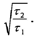
- If T2 is 100 seconds and T1 is 1 second for example, the accumulated integration error after 106 seconds can be reduced to be on the order of 1 psi with two new DP sensors of .01 psi and 1 psi errors respectively (for range 1 psi and 100 psi respectively). Sensors with improved errors would lead to correspondingly improved final error on estimates of absolute P.
- This argument is not a complete proof because the integrals needed for the various calculations mentioned above are not exactly equal, but they should be closely related enough that their accumulated errors are similar, so that a Kalman estimate of one can be used to correct the other. The use of more than two DP sensors with different time constants can further reduce the integration errors.
- All the measurements are sensitive to temperature. Therefore, independent temperature measurements can be made to enable temperature corrections, as is done for current downhole pressure sensors.
- In Figure 1, the device has one side with cavity and capillary, while the other side is directly exposed to the outside pressure. In a third embodiment of the invention, cavities and/or capillaries can be provided on both sides of the membrane, as long as they provided different frequency responses: if the time constant of the cavity/capillary on one side is short, while the other is long, the ensemble still responds to the derivative of the pressure with a time constant equal to the longest of the two.
- From the calculations shown above, it is clear that the behaviour of the device (Figure 1) can be considered equivalent to that of the electrical circuit shown in Figure 2, with the correspondence between pressure and voltage, and between current and flow rate.
- Thus, the design can be generalised to more complex arrangements of capillaries and cavities. For example, the design of Figure 3 with two capillaries and two cavities is equivalent to the circuit of figure 4. The embodiment of Figure 3 comprises a
first cavity body 10a having themembrane 12a which is connected to a second,intermediate cavity body 10b by means of asecond capillary 14b. Thesecond cavity body 10b is connected to the outside pressure P2 by thefist capillary 14a. - This is now a second order filter and can be generalized to a filter of any order. With current MEMS technology, arbitrary geometries of capillaries and cavities can be easily made, so one can have a sensor that measures pressure P(t) minus a filtered version of P(t), with an arbitrary filter. This can be used for two purposes:
- Providing a sensor that measures directly a better approximation of dP/dt than can be achieved with the simple design, by choosing a more sophisticated filter.
- Providing an array of sensors in which each measures the same property with a different filter. With appropriate filters and a sufficiently large number of sensors, it should be possible to reconstruct P(t) with any desired accuracy. In principle, knowledge of filtered versions of a function through an infinite set of filters of order 1, 2, 3 ... n, ... is equivalent to knowledge of the original function. Cutting off the series at order N simply limits the accuracy on the reconstruction, with accuracy improving with increasing with N, as long as the dP/dt is bounded.
- In an alternative embodiment, the two cavities can be on either side of the membrane, each cavity having its own capillary.
- Other changes can be made to the sensor within the scope of the invention.
- In use in a well test, a portion of the well isolated and fluid withdrawn so that the isolated portion is well below the formation pressure. As fluid flows from the formation into the isolated portion, the pressure rises until it is again balancing the formation pressure. Measuring the rate of change of pressure in the isolated portion of the well using the embodiments of the invention described above allows the formation properties to be estimated using known techniques.
Claims (10)
- Apparatus for determining the rate of change of pressure in a well, comprising:- a first cavity body defining an enclosed volume, at least part of one wall of the cavity body being constituted by a pressure sensitive membrane which, in use, is exposed to the well pressure so as to be responsive thereto; and- a first capillary connected to the first cavity body at one end and being open to the well pressure at the other end so as to provide pressure communication between the well pressure and the interior of the first cavity body;wherein the first cavity body and first capillary are configured such that the apparatus has a pressure response that comprises an input minus a low-pass filtered version of the input.
- Apparatus as claimed in claim 1, comprising a second cavity body and a second capillary connected to the first cavity body so as to provide a different frequency response.
- Apparatus as claimed in claim 2, wherein the second cavity body is connected to the first cavity body by means of the second capillary; the first capillary being connected to the second cavity body.
- Apparatus as claimed in claim 2, wherein the second cavity body is positioned on the opposite side of the pressure sensitive membrane to the first cavity body and the second capillary is connected to the second cavity body so as to provide pressure communication between the well pressure and the interior of the second cavity body.
- An array for making pressure measurements in a well, comprising at least two embodiments of the apparatus as claimed in any preceding claim having different time constants.
- The use of an apparatus as claimed in any or claims 1-4 in determining the rate of change of pressure in a well during a well test.
- A method of determining the rate of change of pressure in a well during a well test using an apparatus as claimed in any of claims 1-4, comprising:- measuring the response of the pressure sensitive membrane over the duration of the well test;- determining the time constant of the apparatus used to make the measurements; and- determining the rate of change of the well pressure from the response of the pressure sensitive membrane and the time constant of the apparatus.
- A method as claimed in claim 7, comprising exposing the pressure sensitive membrane and the open end of the first capillary to the same region of the well in which the rate of change is determined.
- A method as claimed in claim 7 or 8, further comprising using the determined rate of change of pressure to provide measurements of permeability, skin and/or reservoir boundaries in the formation around the well.
- A method of determining the absolute pressure in a formation surrounding a well during a well test using an array as claimed in claim 5, comprising:- measuring the responses of the pressure sensitive membranes over the duration of the well test;- determining the time constants of the apparatuses used to make the measurements;- determining the rate of change of the well pressure from the responses of the pressure sensitive membranes and the time constants of the apparatuses; and- integrating the rate of change of well pressure determined by the different apparatuses over the duration of the test to obtain the absolute pressure.
Priority Applications (6)
| Application Number | Priority Date | Filing Date | Title |
|---|---|---|---|
| AT06291587T ATE495429T1 (en) | 2006-10-09 | 2006-10-09 | METHOD AND DEVICE FOR PRESSURE MEASUREMENTS FOR EXAMINING A BOREHOLE |
| DE602006019602T DE602006019602D1 (en) | 2006-10-09 | 2006-10-09 | Method and device for pressure measurements for the investigation of a borehole |
| EP06291587A EP1912052B1 (en) | 2006-10-09 | 2006-10-09 | Method and apparatus for pressure measurements in well testing |
| CNA2007800376821A CN101523181A (en) | 2006-10-09 | 2007-10-09 | Method and apparatus for pressure measurement in oil and gas well testing |
| US12/444,857 US8028571B2 (en) | 2006-10-09 | 2007-10-09 | Method and apparatus for pressure measurements in well testing |
| PCT/EP2007/060731 WO2008043769A1 (en) | 2006-10-09 | 2007-10-09 | Method and apparatus for pressure measurements in well testing |
Applications Claiming Priority (1)
| Application Number | Priority Date | Filing Date | Title |
|---|---|---|---|
| EP06291587A EP1912052B1 (en) | 2006-10-09 | 2006-10-09 | Method and apparatus for pressure measurements in well testing |
Publications (2)
| Publication Number | Publication Date |
|---|---|
| EP1912052A1 true EP1912052A1 (en) | 2008-04-16 |
| EP1912052B1 EP1912052B1 (en) | 2011-01-12 |
Family
ID=37745977
Family Applications (1)
| Application Number | Title | Priority Date | Filing Date |
|---|---|---|---|
| EP06291587A Not-in-force EP1912052B1 (en) | 2006-10-09 | 2006-10-09 | Method and apparatus for pressure measurements in well testing |
Country Status (6)
| Country | Link |
|---|---|
| US (1) | US8028571B2 (en) |
| EP (1) | EP1912052B1 (en) |
| CN (1) | CN101523181A (en) |
| AT (1) | ATE495429T1 (en) |
| DE (1) | DE602006019602D1 (en) |
| WO (1) | WO2008043769A1 (en) |
Families Citing this family (9)
| Publication number | Priority date | Publication date | Assignee | Title |
|---|---|---|---|---|
| JP2013024574A (en) * | 2011-07-15 | 2013-02-04 | Azbil Corp | System and method for diagnosis of clogging in pressure connecting pipe |
| US9964459B2 (en) | 2014-11-03 | 2018-05-08 | Quartzdyne, Inc. | Pass-throughs for use with sensor assemblies, sensor assemblies including at least one pass-through and related methods |
| US10132156B2 (en) | 2014-11-03 | 2018-11-20 | Quartzdyne, Inc. | Downhole distributed pressure sensor arrays, downhole pressure sensors, downhole distributed pressure sensor arrays including quartz resonator sensors, and related methods |
| CN104819798B (en) * | 2015-05-08 | 2017-05-10 | 西南科技大学 | A sensor for on-line monitoring of water pressure change in tailings leaching experiments |
| FR3076850B1 (en) | 2017-12-18 | 2022-04-01 | Quartzdyne Inc | NETWORKS OF DISTRIBUTED SENSORS FOR MEASURING ONE OR MORE PRESSURES AND TEMPERATURES AND ASSOCIATED METHODS AND ASSEMBLIES |
| CN110984973A (en) * | 2019-11-29 | 2020-04-10 | 中国石油集团川庆钻探工程有限公司 | Determination method of single well controlled reserves in fractured-cavity carbonate gas reservoirs |
| CN111572524B (en) * | 2020-05-07 | 2021-03-23 | 武汉理工大学 | A method and device for measuring the rate of change of vehicle pneumatic brake pressure |
| US12234719B2 (en) * | 2020-07-30 | 2025-02-25 | Schlumberger Technology Corporation | Methods for determining a position of a droppable object in a wellbore |
| CN115126482B (en) * | 2022-07-06 | 2024-08-09 | 西南石油大学 | A method for selecting a gas well back pressure test well |
Citations (5)
| Publication number | Priority date | Publication date | Assignee | Title |
|---|---|---|---|---|
| US3350932A (en) * | 1967-03-20 | 1967-11-07 | Exxon Production Research Co | System for measuring changes in fluid pressure |
| GB1131892A (en) * | 1966-02-03 | 1968-10-30 | Exxon Production Research Co | Method and apparatus for measuring changes in borehole fluid pressures |
| US4507971A (en) | 1980-07-29 | 1985-04-02 | Bodenseewerk Geratetechnik Gmbh | Hydraulic filter for eliminating slow pressure fluctuations |
| US4712430A (en) * | 1986-04-04 | 1987-12-15 | Dynisco, Inc. | Pressure transducer |
| US5509312A (en) * | 1993-05-25 | 1996-04-23 | Schlumberger Technology Corporation | Diaphragm pressure sensor including anti-stock protection means and gradiomanometer incorporating such a sensor |
Family Cites Families (1)
| Publication number | Priority date | Publication date | Assignee | Title |
|---|---|---|---|---|
| US5637790A (en) * | 1996-02-28 | 1997-06-10 | De Corral; Jose L. | Three capillary flow-through viscometer |
-
2006
- 2006-10-09 EP EP06291587A patent/EP1912052B1/en not_active Not-in-force
- 2006-10-09 DE DE602006019602T patent/DE602006019602D1/en active Active
- 2006-10-09 AT AT06291587T patent/ATE495429T1/en not_active IP Right Cessation
-
2007
- 2007-10-09 WO PCT/EP2007/060731 patent/WO2008043769A1/en not_active Ceased
- 2007-10-09 CN CNA2007800376821A patent/CN101523181A/en active Pending
- 2007-10-09 US US12/444,857 patent/US8028571B2/en not_active Expired - Fee Related
Patent Citations (5)
| Publication number | Priority date | Publication date | Assignee | Title |
|---|---|---|---|---|
| GB1131892A (en) * | 1966-02-03 | 1968-10-30 | Exxon Production Research Co | Method and apparatus for measuring changes in borehole fluid pressures |
| US3350932A (en) * | 1967-03-20 | 1967-11-07 | Exxon Production Research Co | System for measuring changes in fluid pressure |
| US4507971A (en) | 1980-07-29 | 1985-04-02 | Bodenseewerk Geratetechnik Gmbh | Hydraulic filter for eliminating slow pressure fluctuations |
| US4712430A (en) * | 1986-04-04 | 1987-12-15 | Dynisco, Inc. | Pressure transducer |
| US5509312A (en) * | 1993-05-25 | 1996-04-23 | Schlumberger Technology Corporation | Diaphragm pressure sensor including anti-stock protection means and gradiomanometer incorporating such a sensor |
Non-Patent Citations (4)
| Title |
|---|
| ARTHUR S. IBERALL: "Attenuation of Oscillatory Pressures in Instrument Lines", JOURNAL OF RESEARCH OF THE NATIONAL BUREAU OF STANDARDS, vol. 45, July 1950 (1950-07-01), pages 85 - 108, XP008075608 * |
| CHARLES COX ET AL: "A Deep-Sea Differential Pressure Gauge", JOURNAL OF ATMOSPHERIC AND OCEANIC TECHNOLOGY, vol. 1, September 1984 (1984-09-01), pages 237 - 246, XP008075609 * |
| COX, C. ET AL.: "A Deep-Sea Differential Pressure Gauge", JOURNAL OF ATMOSPHERIC AND OCEANIC TECHNOLOGY, vol. 1, September 1984 (1984-09-01), pages 237 - 246 |
| DIRK DE BRUYKER AND ROBERT PUERS: "Experimental characterization of the reference channel of a differential pressure sensor using pressure shock waves", JOURNAL OF MICROMECHANICS AND MICROENGINEERING, vol. 11, no. 4, July 2001 (2001-07-01), pages 390 - 396, XP002421815 * |
Also Published As
| Publication number | Publication date |
|---|---|
| DE602006019602D1 (en) | 2011-02-24 |
| WO2008043769A1 (en) | 2008-04-17 |
| US20100095759A1 (en) | 2010-04-22 |
| CN101523181A (en) | 2009-09-02 |
| EP1912052B1 (en) | 2011-01-12 |
| ATE495429T1 (en) | 2011-01-15 |
| US8028571B2 (en) | 2011-10-04 |
Similar Documents
| Publication | Publication Date | Title |
|---|---|---|
| US8028571B2 (en) | Method and apparatus for pressure measurements in well testing | |
| CN100432372C (en) | Methods of Determining Formation Pressure | |
| EP0362010B1 (en) | Downhole tool and method for determination of formation properties | |
| US6098448A (en) | In situ measurement apparatus and method of measuring soil permeability and fluid flow | |
| AU2014228702B2 (en) | Passive acoustic resonator for fiber optic cable tubing | |
| US9739142B2 (en) | Fiber optic vibration monitoring | |
| WO2009086279A2 (en) | Acoustic measurements with downhole sampling and testing tools | |
| US8612154B2 (en) | Measurement of sound speed of downhole fluid by helmholtz resonator | |
| CN101454662A (en) | Downhole Fluid Characterization Based on Variation of Acoustic Properties with Pressure | |
| US7448263B2 (en) | Practical methods to estimate horizontal and vertical permeabilities | |
| US7448262B2 (en) | Determination of correct horizontal and vertical permeabilities in a deviated well | |
| US7181960B2 (en) | Determination of correct horizontal and vertical permeabilities in a deviated well | |
| RU2316650C2 (en) | Method and downhole tool for underground reservoir survey (variants) | |
| EP1619520A1 (en) | Method and apparatus for estimating a permeability distribution during a well test | |
| CA2231947C (en) | Method of determining fluid inflow rates | |
| CN100523431C (en) | Method for simulating oil-water two-phase cable formation testing | |
| IT201900009873A1 (en) | DETECTION SYSTEM TO DETECT DISCONTINUITY INTERFACES AND / OR ANOMALIES IN THE PRESSURE OF THE PORES IN GEOLOGICAL FORMATIONS. | |
| WO1998046858A1 (en) | In situ measurement apparatus and method of measuring soil permeability and fluid flow | |
| Michaels et al. | Advances in wireline formation testing | |
| US7150188B2 (en) | Non-invasive measurement of fluid-pressure diffusivity using electro-osmosis | |
| JPH06167406A (en) | Differential pressure type pressure change measuring device | |
| Lee et al. | Precision Pressure Gradient through Disciplined Pressure Survey |
Legal Events
| Date | Code | Title | Description |
|---|---|---|---|
| PUAI | Public reference made under article 153(3) epc to a published international application that has entered the european phase |
Free format text: ORIGINAL CODE: 0009012 |
|
| AK | Designated contracting states |
Kind code of ref document: A1 Designated state(s): AT BE BG CH CY CZ DE DK EE ES FI FR GB GR HU IE IS IT LI LT LU LV MC NL PL PT RO SE SI SK TR |
|
| AX | Request for extension of the european patent |
Extension state: AL BA HR MK RS |
|
| 17P | Request for examination filed |
Effective date: 20081002 |
|
| 17Q | First examination report despatched |
Effective date: 20081112 |
|
| AKX | Designation fees paid |
Designated state(s): AT BE BG CH CY CZ DE DK EE ES FI FR GB GR HU IE IS IT LI LT LU LV MC NL PL PT RO SE SI SK TR |
|
| R17P | Request for examination filed (corrected) |
Effective date: 20081002 |
|
| R17P | Request for examination filed (corrected) |
Effective date: 20081002 |
|
| GRAP | Despatch of communication of intention to grant a patent |
Free format text: ORIGINAL CODE: EPIDOSNIGR1 |
|
| GRAS | Grant fee paid |
Free format text: ORIGINAL CODE: EPIDOSNIGR3 |
|
| GRAA | (expected) grant |
Free format text: ORIGINAL CODE: 0009210 |
|
| AK | Designated contracting states |
Kind code of ref document: B1 Designated state(s): AT BE BG CH CY CZ DE DK EE ES FI FR GB GR HU IE IS IT LI LT LU LV MC NL PL PT RO SE SI SK TR |
|
| REG | Reference to a national code |
Ref country code: GB Ref legal event code: FG4D |
|
| REG | Reference to a national code |
Ref country code: CH Ref legal event code: EP |
|
| REG | Reference to a national code |
Ref country code: IE Ref legal event code: FG4D |
|
| REF | Corresponds to: |
Ref document number: 602006019602 Country of ref document: DE Date of ref document: 20110224 Kind code of ref document: P |
|
| REG | Reference to a national code |
Ref country code: DE Ref legal event code: R096 Ref document number: 602006019602 Country of ref document: DE Effective date: 20110224 |
|
| REG | Reference to a national code |
Ref country code: NL Ref legal event code: VDEP Effective date: 20110112 |
|
| LTIE | Lt: invalidation of european patent or patent extension |
Effective date: 20110112 |
|
| PG25 | Lapsed in a contracting state [announced via postgrant information from national office to epo] |
Ref country code: GR Free format text: LAPSE BECAUSE OF FAILURE TO SUBMIT A TRANSLATION OF THE DESCRIPTION OR TO PAY THE FEE WITHIN THE PRESCRIBED TIME-LIMIT Effective date: 20110413 Ref country code: IS Free format text: LAPSE BECAUSE OF FAILURE TO SUBMIT A TRANSLATION OF THE DESCRIPTION OR TO PAY THE FEE WITHIN THE PRESCRIBED TIME-LIMIT Effective date: 20110512 Ref country code: ES Free format text: LAPSE BECAUSE OF FAILURE TO SUBMIT A TRANSLATION OF THE DESCRIPTION OR TO PAY THE FEE WITHIN THE PRESCRIBED TIME-LIMIT Effective date: 20110423 Ref country code: PT Free format text: LAPSE BECAUSE OF FAILURE TO SUBMIT A TRANSLATION OF THE DESCRIPTION OR TO PAY THE FEE WITHIN THE PRESCRIBED TIME-LIMIT Effective date: 20110512 Ref country code: LT Free format text: LAPSE BECAUSE OF FAILURE TO SUBMIT A TRANSLATION OF THE DESCRIPTION OR TO PAY THE FEE WITHIN THE PRESCRIBED TIME-LIMIT Effective date: 20110112 Ref country code: LV Free format text: LAPSE BECAUSE OF FAILURE TO SUBMIT A TRANSLATION OF THE DESCRIPTION OR TO PAY THE FEE WITHIN THE PRESCRIBED TIME-LIMIT Effective date: 20110112 Ref country code: SE Free format text: LAPSE BECAUSE OF FAILURE TO SUBMIT A TRANSLATION OF THE DESCRIPTION OR TO PAY THE FEE WITHIN THE PRESCRIBED TIME-LIMIT Effective date: 20110112 |
|
| PG25 | Lapsed in a contracting state [announced via postgrant information from national office to epo] |
Ref country code: NL Free format text: LAPSE BECAUSE OF FAILURE TO SUBMIT A TRANSLATION OF THE DESCRIPTION OR TO PAY THE FEE WITHIN THE PRESCRIBED TIME-LIMIT Effective date: 20110112 Ref country code: FI Free format text: LAPSE BECAUSE OF FAILURE TO SUBMIT A TRANSLATION OF THE DESCRIPTION OR TO PAY THE FEE WITHIN THE PRESCRIBED TIME-LIMIT Effective date: 20110112 Ref country code: CY Free format text: LAPSE BECAUSE OF FAILURE TO SUBMIT A TRANSLATION OF THE DESCRIPTION OR TO PAY THE FEE WITHIN THE PRESCRIBED TIME-LIMIT Effective date: 20110112 Ref country code: BG Free format text: LAPSE BECAUSE OF FAILURE TO SUBMIT A TRANSLATION OF THE DESCRIPTION OR TO PAY THE FEE WITHIN THE PRESCRIBED TIME-LIMIT Effective date: 20110412 Ref country code: AT Free format text: LAPSE BECAUSE OF FAILURE TO SUBMIT A TRANSLATION OF THE DESCRIPTION OR TO PAY THE FEE WITHIN THE PRESCRIBED TIME-LIMIT Effective date: 20110112 Ref country code: SI Free format text: LAPSE BECAUSE OF FAILURE TO SUBMIT A TRANSLATION OF THE DESCRIPTION OR TO PAY THE FEE WITHIN THE PRESCRIBED TIME-LIMIT Effective date: 20110112 Ref country code: PL Free format text: LAPSE BECAUSE OF FAILURE TO SUBMIT A TRANSLATION OF THE DESCRIPTION OR TO PAY THE FEE WITHIN THE PRESCRIBED TIME-LIMIT Effective date: 20110112 Ref country code: BE Free format text: LAPSE BECAUSE OF FAILURE TO SUBMIT A TRANSLATION OF THE DESCRIPTION OR TO PAY THE FEE WITHIN THE PRESCRIBED TIME-LIMIT Effective date: 20110112 |
|
| PG25 | Lapsed in a contracting state [announced via postgrant information from national office to epo] |
Ref country code: DK Free format text: LAPSE BECAUSE OF FAILURE TO SUBMIT A TRANSLATION OF THE DESCRIPTION OR TO PAY THE FEE WITHIN THE PRESCRIBED TIME-LIMIT Effective date: 20110112 Ref country code: EE Free format text: LAPSE BECAUSE OF FAILURE TO SUBMIT A TRANSLATION OF THE DESCRIPTION OR TO PAY THE FEE WITHIN THE PRESCRIBED TIME-LIMIT Effective date: 20110112 |
|
| PLBE | No opposition filed within time limit |
Free format text: ORIGINAL CODE: 0009261 |
|
| STAA | Information on the status of an ep patent application or granted ep patent |
Free format text: STATUS: NO OPPOSITION FILED WITHIN TIME LIMIT |
|
| PG25 | Lapsed in a contracting state [announced via postgrant information from national office to epo] |
Ref country code: CZ Free format text: LAPSE BECAUSE OF FAILURE TO SUBMIT A TRANSLATION OF THE DESCRIPTION OR TO PAY THE FEE WITHIN THE PRESCRIBED TIME-LIMIT Effective date: 20110112 Ref country code: SK Free format text: LAPSE BECAUSE OF FAILURE TO SUBMIT A TRANSLATION OF THE DESCRIPTION OR TO PAY THE FEE WITHIN THE PRESCRIBED TIME-LIMIT Effective date: 20110112 Ref country code: RO Free format text: LAPSE BECAUSE OF FAILURE TO SUBMIT A TRANSLATION OF THE DESCRIPTION OR TO PAY THE FEE WITHIN THE PRESCRIBED TIME-LIMIT Effective date: 20110112 |
|
| 26N | No opposition filed |
Effective date: 20111013 |
|
| PG25 | Lapsed in a contracting state [announced via postgrant information from national office to epo] |
Ref country code: IT Free format text: LAPSE BECAUSE OF FAILURE TO SUBMIT A TRANSLATION OF THE DESCRIPTION OR TO PAY THE FEE WITHIN THE PRESCRIBED TIME-LIMIT Effective date: 20110112 |
|
| REG | Reference to a national code |
Ref country code: DE Ref legal event code: R097 Ref document number: 602006019602 Country of ref document: DE Effective date: 20111013 |
|
| PG25 | Lapsed in a contracting state [announced via postgrant information from national office to epo] |
Ref country code: MC Free format text: LAPSE BECAUSE OF NON-PAYMENT OF DUE FEES Effective date: 20111031 |
|
| REG | Reference to a national code |
Ref country code: CH Ref legal event code: PL |
|
| GBPC | Gb: european patent ceased through non-payment of renewal fee |
Effective date: 20111009 |
|
| PG25 | Lapsed in a contracting state [announced via postgrant information from national office to epo] |
Ref country code: DE Free format text: LAPSE BECAUSE OF NON-PAYMENT OF DUE FEES Effective date: 20120501 Ref country code: LI Free format text: LAPSE BECAUSE OF NON-PAYMENT OF DUE FEES Effective date: 20111031 Ref country code: CH Free format text: LAPSE BECAUSE OF NON-PAYMENT OF DUE FEES Effective date: 20111031 |
|
| REG | Reference to a national code |
Ref country code: IE Ref legal event code: MM4A |
|
| REG | Reference to a national code |
Ref country code: DE Ref legal event code: R119 Ref document number: 602006019602 Country of ref document: DE Effective date: 20120501 |
|
| PG25 | Lapsed in a contracting state [announced via postgrant information from national office to epo] |
Ref country code: GB Free format text: LAPSE BECAUSE OF NON-PAYMENT OF DUE FEES Effective date: 20111009 |
|
| PG25 | Lapsed in a contracting state [announced via postgrant information from national office to epo] |
Ref country code: IE Free format text: LAPSE BECAUSE OF NON-PAYMENT OF DUE FEES Effective date: 20111009 |
|
| PG25 | Lapsed in a contracting state [announced via postgrant information from national office to epo] |
Ref country code: LU Free format text: LAPSE BECAUSE OF NON-PAYMENT OF DUE FEES Effective date: 20111009 |
|
| PG25 | Lapsed in a contracting state [announced via postgrant information from national office to epo] |
Ref country code: TR Free format text: LAPSE BECAUSE OF FAILURE TO SUBMIT A TRANSLATION OF THE DESCRIPTION OR TO PAY THE FEE WITHIN THE PRESCRIBED TIME-LIMIT Effective date: 20110112 |
|
| PG25 | Lapsed in a contracting state [announced via postgrant information from national office to epo] |
Ref country code: HU Free format text: LAPSE BECAUSE OF FAILURE TO SUBMIT A TRANSLATION OF THE DESCRIPTION OR TO PAY THE FEE WITHIN THE PRESCRIBED TIME-LIMIT Effective date: 20110112 |
|
| PGFP | Annual fee paid to national office [announced via postgrant information from national office to epo] |
Ref country code: FR Payment date: 20141008 Year of fee payment: 9 |
|
| REG | Reference to a national code |
Ref country code: FR Ref legal event code: ST Effective date: 20160630 |
|
| PG25 | Lapsed in a contracting state [announced via postgrant information from national office to epo] |
Ref country code: FR Free format text: LAPSE BECAUSE OF NON-PAYMENT OF DUE FEES Effective date: 20151102 |