EP1911950A2 - Air bypass apparatus in fuel injection apparatus - Google Patents
Air bypass apparatus in fuel injection apparatus Download PDFInfo
- Publication number
- EP1911950A2 EP1911950A2 EP07117654A EP07117654A EP1911950A2 EP 1911950 A2 EP1911950 A2 EP 1911950A2 EP 07117654 A EP07117654 A EP 07117654A EP 07117654 A EP07117654 A EP 07117654A EP 1911950 A2 EP1911950 A2 EP 1911950A2
- Authority
- EP
- European Patent Office
- Prior art keywords
- air control
- control valve
- air
- bottom portion
- slider
- Prior art date
- Legal status (The legal status is an assumption and is not a legal conclusion. Google has not performed a legal analysis and makes no representation as to the accuracy of the status listed.)
- Granted
Links
Images


Classifications
-
- F—MECHANICAL ENGINEERING; LIGHTING; HEATING; WEAPONS; BLASTING
- F02—COMBUSTION ENGINES; HOT-GAS OR COMBUSTION-PRODUCT ENGINE PLANTS
- F02M—SUPPLYING COMBUSTION ENGINES IN GENERAL WITH COMBUSTIBLE MIXTURES OR CONSTITUENTS THEREOF
- F02M3/00—Idling devices for carburettors
- F02M3/08—Other details of idling devices
- F02M3/09—Valves responsive to engine conditions, e.g. manifold vacuum
-
- F—MECHANICAL ENGINEERING; LIGHTING; HEATING; WEAPONS; BLASTING
- F02—COMBUSTION ENGINES; HOT-GAS OR COMBUSTION-PRODUCT ENGINE PLANTS
- F02D—CONTROLLING COMBUSTION ENGINES
- F02D9/00—Controlling engines by throttling air or fuel-and-air induction conduits or exhaust conduits
- F02D9/08—Throttle valves specially adapted therefor; Arrangements of such valves in conduits
- F02D9/10—Throttle valves specially adapted therefor; Arrangements of such valves in conduits having pivotally-mounted flaps
- F02D9/1035—Details of the valve housing
- F02D9/1055—Details of the valve housing having a fluid by-pass
-
- F—MECHANICAL ENGINEERING; LIGHTING; HEATING; WEAPONS; BLASTING
- F02—COMBUSTION ENGINES; HOT-GAS OR COMBUSTION-PRODUCT ENGINE PLANTS
- F02M—SUPPLYING COMBUSTION ENGINES IN GENERAL WITH COMBUSTIBLE MIXTURES OR CONSTITUENTS THEREOF
- F02M23/00—Apparatus for adding secondary air to fuel-air mixture
- F02M23/006—Valves specially shaped for supplying secondary air
-
- F—MECHANICAL ENGINEERING; LIGHTING; HEATING; WEAPONS; BLASTING
- F02—COMBUSTION ENGINES; HOT-GAS OR COMBUSTION-PRODUCT ENGINE PLANTS
- F02D—CONTROLLING COMBUSTION ENGINES
- F02D9/00—Controlling engines by throttling air or fuel-and-air induction conduits or exhaust conduits
- F02D9/02—Controlling engines by throttling air or fuel-and-air induction conduits or exhaust conduits concerning induction conduits
- F02D2009/0201—Arrangements; Control features; Details thereof
- F02D2009/0252—Opening a special valve-controlled intake passage (by-pass) during starting
-
- F—MECHANICAL ENGINEERING; LIGHTING; HEATING; WEAPONS; BLASTING
- F02—COMBUSTION ENGINES; HOT-GAS OR COMBUSTION-PRODUCT ENGINE PLANTS
- F02M—SUPPLYING COMBUSTION ENGINES IN GENERAL WITH COMBUSTIBLE MIXTURES OR CONSTITUENTS THEREOF
- F02M69/00—Low-pressure fuel-injection apparatus ; Apparatus with both continuous and intermittent injection; Apparatus injecting different types of fuel
- F02M69/04—Injectors peculiar thereto
- F02M69/042—Positioning of injectors with respect to engine, e.g. in the air intake conduit
-
- Y—GENERAL TAGGING OF NEW TECHNOLOGICAL DEVELOPMENTS; GENERAL TAGGING OF CROSS-SECTIONAL TECHNOLOGIES SPANNING OVER SEVERAL SECTIONS OF THE IPC; TECHNICAL SUBJECTS COVERED BY FORMER USPC CROSS-REFERENCE ART COLLECTIONS [XRACs] AND DIGESTS
- Y02—TECHNOLOGIES OR APPLICATIONS FOR MITIGATION OR ADAPTATION AGAINST CLIMATE CHANGE
- Y02T—CLIMATE CHANGE MITIGATION TECHNOLOGIES RELATED TO TRANSPORTATION
- Y02T10/00—Road transport of goods or passengers
- Y02T10/10—Internal combustion engine [ICE] based vehicles
- Y02T10/12—Improving ICE efficiencies
Definitions
- the present invention relates to a fuel injection apparatus in which fuel within a fuel tank is boosted by a fuel pump, and the boosted fuel is injected and supplied to an engine via a fuel injection valve, and more particularly to an air bypass apparatus supplying controlled idle air into an intake passage at a downstream side of a throttle valve while bypassing the throttle valve, at a time of an idling operation of the engine and at a time of an off-idle operation.
- a conventional air bypass apparatus is disclosed in PCT/JP2005/006560 and Japanese Patent Application No. 2005-324824 , a whole structure of the air bypass apparatus is disclosed in PCT/JP2005/006560 , and a locking structure between a slider and an air control valve is disclosed in Japanese Patent Application No. 2005-32482 .
- FIG. 8 A structure of an air bypass apparatus arranged on the basis of PCT/JP2005/006560 is disclosed in Fig. 8, and will be explained by this drawing.
- Reference numeral 10 denotes an air control valve main body in which a motor insertion hole 11 and a valve body guide hole 12 are continuously provided from an upper end surface 10a toward a lower side.
- An air control hole 13 is open to a side wall 12a of the valve guide hole 12, and a downstream side of the air control hole 13 is open so as to communicate with an inner side of an intake passage 15 passing through a throttle body 14 and an inner side of an intake passage 15a at a downstream side of a throttle valve 16.
- an air inflow hole 17 is open to a portion near a bottom portion 12b of the valve body guide hole 12, and an upstream side of the air inflow hole 17 is open so as to communicate with an inner side of an intake passage 15b at an upstream side of the throttle valve 16. (In the description mentioned above, the upstream side and the downstream side are called in an air flow direction.)
- the intake passage 15b at the upstream side communicate with an air cleaner (not shown) by an air pipe
- the intake passage 15a at the downstream side communicate with an engine (not shown) by an intake pipe
- a fuel controlled by a fuel injection valve (not shown) is injected and supplied into the intake passage 15 or the intake pipe.
- Reference symbol M denotes a motor such as a step motor or the like in which an output shaft Ma protrudes toward a lower side.
- a motor case Mb formed by a synthetic resin material is out molded in an outer periphery of the motor M, and a tube portion Mc surrounding the output shaft Ma is formed in the motor case Mb so as to be open toward a lower side.
- Reference numeral 17 denotes a rotation suppressing member formed in a tubular shape.
- a rotation suppressing groove 17b is provided in an inner peripheral wall 17a thereof in a vertical direction in the drawing, and the rotation suppressing member 17 is inserted into the tube portion Mc from a lower opening of the tube portion Mc so as to be fixed. For example, it is light pressure inserted.
- the rotation suppressing member 17 is fixedly arranged in an inner side of the tube portion Mc of the motor case Mb provided with the motor M, and the output shaft Ma is arranged in an inner side of the inner peripheral wall 17a of the rotation suppressing member 17.
- the motor case Mb is structured such that a U-shaped groove of a tabular attaching member 18 is fitted to an inner side of an annular groove Md provided in an outer periphery of the tube portion Mc as well as a lower side of the tube portion Mc is inserted into the motor insertion hole 11 of the air control valve main body 10, and the attaching member 18 is fixed by screw to the air control valve main body 10 via a screw 19 as well as being arranged on an upper end surface 10a of the air control valve main body 10 in a contact manner.
- Reference numeral 20 denotes a slider screwed to a male thread formed on an outer periphery of the output shaft Ma.
- the slider 20 is formed by an annular collar portion 20a and a shaft portion 20b protruding toward a lower side from the annular collar portion 20a, and a protruding portion 20c inserted into the rotation suppressing groove 17b of the rotation suppressing member 17 is integrally formed at a part of an outer periphery of the annular collar portion 20a so as to protrude sideward.
- Reference numeral 21 denotes an air control valve arranged within the valve body guide hole 12 so as to be movable in a vertical direction, and is formed in a closed-end tubular shape in which a tube portion 21b is integrally formed from a bottom portion 21a toward an upper side.
- the air control valve 21 mentioned above is arranged so as to face to an outer periphery 20d of the shaft portion 20b of the slider 20, and a bottom portion 21a thereof is arranged on an E clip 22 fixedly arranged so as to be fitted to a lower end of the shaft portion 20b of the slider 20 in such a manner as to be brought into contact by a spring 23.
- a contracted spring 23 is arranged in a space portion 25 formed between an inner side of the tube portion 21b and the outer periphery 20d of the shaft portion 20b, one end 23a of the spring 23 is locked to a lower surface of the annular collar portion 20a of the slider 20, and the other end 23b is locked to the bottom portion 21a of the air control valve 21. Accordingly, the bottom portion 21a of the air control valve 21 is elastically held so as to be pressed toward the E clip 22.
- the air bypass apparatus structured as mentioned above, when the motor M including the output shaft 13a is rotated in one direction, the rotation of the slider 20 is suppressed by the rotation suppressing groove 17b and the protruding portion 20c, thereby being moved, for example, in a downward direction in the drawing. Further, since the air control valve 21 is also synchronously moved in the downward direction on the basis of the downward movement of the slider 20, it is possible to control an opening area of the air control hole 13 in a reducing direction by the air control valve 21, and it is possible to regulate and control an amount of idle air supplied to the intake passage 15a at the downstream side in the reducing direction.
- the air control valve 21 is also synchronously moved in the upward direction on the basis of the upward movement of the slider 20, it is possible to control the opening area of the air control hole 13 in an increasing direction by the air control valve 21, and it is possible to regulate and control the amount of the idle air supplied to the intake passage 15a at the downstream side in the increasing direction, whereby it is possible to supply a desired amount of the idle air toward the engine.
- a first annular gap S1 is formed between the outer periphery of the air control valve 21 and the valve body guide hole 12, and a second annular gap S2 is formed between an inner periphery 21a1 of a bottom portion 21a of the air control valve 21 and the outer periphery 20d of the shaft portion 20b of the slider 20.
- the annular gaps S1 and S2 are necessary for arranging the air control valve 21 in the valve body guide hole 12 so as to be smoothly movable while taking into consideration a manufacturing error and an assembling error of the air control valve 21, the slider 20, the valve body guide hole 12 and the like.
- the space portion 25 formed between the inner side of the tube portion 21b of the air control valve 21 and the outer periphery 20d of the shaft portion 20b of the slider 20 communicates toward the bottom portion 12b of the valve body guide hole 12 via the second annular gap S2, and the notch grooves 22a1, 22a2 and 22a3 formed in the E clip 22.
- notch grooves 22a1, 22a2 and 22a3 of the E clip mentioned above are disclosed in Fig. 8, and a hatched portion by a one-dot chain line in Fig. 9 corresponds to a portion where the second annular gap S2 communicates with the notch grooves 22a1, 22a2 and 22a3.
- the notch grooves 22a1, 22a2 and 22a3 mentioned above are open so as to face to the bottom portion 12b of the valve body guide hole 12.
- pulsative pressure is generated within the intake passage 15, and the pulsative pressure is applied to the inner side of the valve body guide hole 12 from the air inflow hole 17 and the bottom portion 12b. Further, the pulsative pressure within the valve body guide hole 12 is applied to the space portion 25 at the inner side of the air control valve 21 from the notch grooves 22a1, 22a2 and 22a3 of the E clip 22 via the second annular gap S2.
- the air control valve 21 moves to the side portion (a direction orthogonal to a longitudinal axis X-X of the valve body guide hole 12) slightly in a state in which the lower surface of the bottom portion 21a is brought into contact with the upper end surface of the E clip 22, whereby there is generated dispersion in the set idle air amount even in a state in which the opening degree of the air control valve 21 is held constant (a stroke state in a vertical direction of the air control valve 21 is constant).
- the present invention is made by taking the problem mentioned above into consideration, and an object of the present invention is to provide an air bypass apparatus which can accurately supply an idle air amount without being affected by a pulsative pressure generated within an intake passage in a state in which an opening degree of an air control valve is fixed, and to provide an air bypass apparatus having a high reproducibility of an idle air amount.
- an air bypass apparatus in a fuel injection apparatus comprising:
- the closing member is constituted by a flat washer
- the flat washer is arranged so as to be fitted on the outer periphery of the shaft portion of the slider and is arranged in a contact manner on the lower end surface of the bottom portion of the air control valve by an E clip fixedly attached to the lower end of the shaft portion, and the annular gap is closed by an upper side surface of the flat washer.
- a plurality of the air control holes are open at positions on the side wall in same height from a bottom portion of the valve body guide hole, and each of the air control holes communicates with the intake passage at the downstream side of the throttle valve in each of the throttle bodies constituting a multiple throttle body system.
- the annular gap formed between the inner periphery of the bottom portion of the air control valve and the outer periphery of the shaft portion of the slider is closed by the closing member arranged in a contact manner on the lower end surface of the bottom portion of the air control valve.
- the pulsative pressure generated within the intake passage is applied to the inner side of the bottom portion of the valve body guide hole via the air inflow hole, the pulsative pressure is not applied to the space portion formed between the inner side of the tube portion of the air control valve and the outer periphery of the shaft portion of the slider via the gap.
- the air control valve is not moved in the direction orthogonal to the longitudinal axis of the valve body guide hole, whereby it is possible to supply the idle air accurately and with high reproducibility.
- the air control valve can be inserted in such a manner as to be guided by the valve body guide hole at a time of inserting the air control valve into the valve body guide hole so as to assemble them. Accordingly, an assembling characteristic of the air control valve into the valve body guide hole is not obstructed.
- the same gap as the conventional gap can be used for the first gap between the outer periphery of the tube portion of the air control valve and the valve body guide hole, and the second gap between the inner periphery of the bottom portion of the air control valve and the outer periphery of the shaft portion of the slider, the working man hours and the assembling man hours are not increased.
- the flat washer is used as the closing member, it is possible to inhibit an increase of a part unit cost.
- the conventionally used E clip is used as the locking piece portion, it is possible to utilize the conventional part and the conventional fitting jig, and it is possible to hold down an increase of the manufacturing cost.
- the flat washer since the flat washer is used, it is possible to reduce an increase of a length in the direction of the longitudinal axis of the valve body guide hole, and it is possible to obtain compatibility with the conventional structure.
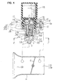
- Fig. 1 is a vertical sectional view of a main portion
- Fig. 2 is an enlarged view of a portion Y in Fig. 1
- Fig. 3 is a cross sectional view along a line Z-Z in Fig. 1.
- Reference numeral 1 denotes a closing member arranged between a locking piece portion 2 such as, for example, an E clip fixedly attached to a lower end of a shaft portion 20b of a slider 20, and a lower end surface 21a2 of a bottom portion 21a of an air control valve 21.
- the closing member 1 has a flat shape, and is formed by an insertion hole 1a fitted on an outer periphery 20d of the shaft portion 20b with a small gap, an upper side surface 1b formed as a flat surface brought into contact with the lower end surface 21a2 of the bottom portion 21a of the air control valve 21, and a lower side surface 1c formed as a flat surface brought into contact with an upper side surface 2a of the locking piece portion 2.
- the air control valve 21 is pressed in a downward direction in the drawing by a spring 23, the lower end surface 21a2 of the bottom portion 21a of the air control valve 21 is brought into contact with the upper side surface 1b of the closing member 1, and the lower side surface 1c of the closing member 1 is elastically pressed to the upper side surface 2a of the locking piece portion 2 so as to be arranged in a contact manner.
- a second gap S2 formed between the inner periphery 21a1 of the bottom portion 21a of the air control valve 21 and the outer periphery 20d of the shaft portion 20b of the slider 20 is closed by the closing member 1.
- the pulsation pressure is shut off by the closing member 1. Accordingly, the pulsative pressure is not applied to the space portion 25 formed between the inner side of the tube portion 21b of the air control valve 21 and the outer periphery 20d of the shaft portion 20b of the slider 20.
- Fig. 3 shows a state in which the second annular gap S2 shown by a one-dot chain line is closed by the closing member 1.
- the air control valve 21 does not move in the direction orthogonal to a longitudinal axis X-X of the valve body guide hole 12, it is possible to always arrange the air control valve 21 within the valve body guide hole 12 in an initially set state, and it is possible to always hold a gap S1a between the valve body guide hole 12 where the air control hole 13 opens and the tube portion 21b of the air control valve 21 facing thereto to be constant.
- the air control valve 21 can be inserted into the valve body guide hole 12 in such a manner as to be guided by the valve body guide hole 12 at a time of inserting the air control valve 21 into the valve body guide hole 12. Accordingly, an assembling characteristic of the air control valve 21 with respect to the valve body guide hole 12 is not obstructed.
- both of the flat washer and the E clip can be generally available parts in the market, and it is possible to prevent a part cost from being increased.
- the flat washer is arranged so as to be fitted on the outer periphery 20d of the shaft portion 20b of the slider, and the E clip is fixedly attached to the outer periphery of the lower end of the shaft portion 20b of the slider, it is possible to utilize the conventional E clip fitting jig as it is, and it is possible to prevent an assembling cost from being increased.
- Figs. 4, 5 and 6 show other embodiments of the locking piece portion 2 in Figs. 4, 5 and 6.
- Fig. 4 shows a structure in which a nut is used as the locking piece portion 2, and the closing member 1 is screwed toward a locking step portion 20g formed on the lower end of the shaft portion 20b of the slider.
- Fig. 5 shows a structure in which a cap is used as the locking piece portion 2 , and the cap is pressure inserted toward the locking step portion 20g of the shaft portion 20b of the slider.
- Fig. 6 shows a structure in which the lower end surface of the shaft portion 20b of the slider is caulked by rolling toward the locking step portion 20g.
- Fig. 7 shows another embodiment in accordance with the present invention, and a description will be given of a different part from Fig. 1.
- a plurality of air control holes are provided at positions on the side wall 12a in same height from the bottom portion 12b of the valve body guide hole 12.
- a first air control hole 4a communicates with an intake passage 7a at a downstream side of a throttle valve 6a in a first throttle body 5a
- a second air control hole 4b communicates with an intake passage 7b at a downstream side of a throttle valve 6b in a second throttle body 5b.
- the pulsative pressure generated within the intake passage in the same manner as the first embodiment shown in Fig. 1 is prevented from moving forward into the space portion 25 by the closing member 1, it is possible to always hold a gap Sr between a right side wall 21r of the air control valve 21 and the valve body guide hole 12 where the first air control hole 4a opens, and a gap S1 between a left side wall 211 of the air control valve 21 and the valve body guide hole 12 where the second air control hole 4b opens, to be constant, whereby it is possible to supply the idle air to each of the intake passages 7a and 7b from the first air control hole 4a and the second air control hole 4b accurately and with high reproducibility.
- the structure is particularly preferable as an air bypass apparatus in a multiple throttle body system.
Landscapes
- Engineering & Computer Science (AREA)
- Chemical & Material Sciences (AREA)
- Combustion & Propulsion (AREA)
- Mechanical Engineering (AREA)
- General Engineering & Computer Science (AREA)
- Control Of Throttle Valves Provided In The Intake System Or In The Exhaust System (AREA)
- Fluid-Driven Valves (AREA)
- Fuel-Injection Apparatus (AREA)
Abstract
Description
- The present invention relates to a fuel injection apparatus in which fuel within a fuel tank is boosted by a fuel pump, and the boosted fuel is injected and supplied to an engine via a fuel injection valve, and more particularly to an air bypass apparatus supplying controlled idle air into an intake passage at a downstream side of a throttle valve while bypassing the throttle valve, at a time of an idling operation of the engine and at a time of an off-idle operation.
- A conventional air bypass apparatus is disclosed in
PCT/JP2005/006560 Japanese Patent Application No. 2005-324824 PCT/JP2005/006560 Japanese Patent Application No. 2005-32482 - A structure of an air bypass apparatus arranged on the basis of
PCT/JP2005/006560 -
Reference numeral 10 denotes an air control valve main body in which amotor insertion hole 11 and a valvebody guide hole 12 are continuously provided from anupper end surface 10a toward a lower side. An air control hole 13 is open to aside wall 12a of thevalve guide hole 12, and a downstream side of the air control hole 13 is open so as to communicate with an inner side of anintake passage 15 passing through athrottle body 14 and an inner side of anintake passage 15a at a downstream side of athrottle valve 16. On the other hand, anair inflow hole 17 is open to a portion near abottom portion 12b of the valvebody guide hole 12, and an upstream side of theair inflow hole 17 is open so as to communicate with an inner side of anintake passage 15b at an upstream side of thethrottle valve 16. (In the description mentioned above, the upstream side and the downstream side are called in an air flow direction.) - In this case, the
intake passage 15b at the upstream side communicate with an air cleaner (not shown) by an air pipe, theintake passage 15a at the downstream side communicate with an engine (not shown) by an intake pipe, and a fuel controlled by a fuel injection valve (not shown) is injected and supplied into theintake passage 15 or the intake pipe. - Reference symbol M denotes a motor such as a step motor or the like in which an output shaft Ma protrudes toward a lower side. A motor case Mb formed by a synthetic resin material is out molded in an outer periphery of the motor M, and a tube portion Mc surrounding the output shaft Ma is formed in the motor case Mb so as to be open toward a lower side.
Reference numeral 17 denotes a rotation suppressing member formed in a tubular shape. Arotation suppressing groove 17b is provided in an innerperipheral wall 17a thereof in a vertical direction in the drawing, and therotation suppressing member 17 is inserted into the tube portion Mc from a lower opening of the tube portion Mc so as to be fixed. For example, it is light pressure inserted. - In accordance with the structure mentioned above, the
rotation suppressing member 17 is fixedly arranged in an inner side of the tube portion Mc of the motor case Mb provided with the motor M, and the output shaft Ma is arranged in an inner side of the innerperipheral wall 17a of therotation suppressing member 17. The motor case Mb is structured such that a U-shaped groove of atabular attaching member 18 is fitted to an inner side of an annular groove Md provided in an outer periphery of the tube portion Mc as well as a lower side of the tube portion Mc is inserted into themotor insertion hole 11 of the air control valvemain body 10, and the attachingmember 18 is fixed by screw to the air control valvemain body 10 via ascrew 19 as well as being arranged on anupper end surface 10a of the air control valvemain body 10 in a contact manner. -
Reference numeral 20 denotes a slider screwed to a male thread formed on an outer periphery of the output shaft Ma. Theslider 20 is formed by anannular collar portion 20a and ashaft portion 20b protruding toward a lower side from theannular collar portion 20a, and a protruding portion 20c inserted into therotation suppressing groove 17b of therotation suppressing member 17 is integrally formed at a part of an outer periphery of theannular collar portion 20a so as to protrude sideward. - In accordance with the structure mentioned above, when the output shaft Ma is rotated in synchronization with the motor M, the rotation of the
slider 20 is suppressed by the protruding portion 20c and therotation suppressing groove 17b, whereby theslider 20 is moved up and down in the drawing in correspondence to the rotating direction of the motor M. -
Reference numeral 21 denotes an air control valve arranged within the valvebody guide hole 12 so as to be movable in a vertical direction, and is formed in a closed-end tubular shape in which atube portion 21b is integrally formed from abottom portion 21a toward an upper side. - The
air control valve 21 mentioned above is arranged so as to face to anouter periphery 20d of theshaft portion 20b of theslider 20, and abottom portion 21a thereof is arranged on anE clip 22 fixedly arranged so as to be fitted to a lower end of theshaft portion 20b of theslider 20 in such a manner as to be brought into contact by aspring 23. In other words, a contractedspring 23 is arranged in aspace portion 25 formed between an inner side of thetube portion 21b and theouter periphery 20d of theshaft portion 20b, oneend 23a of thespring 23 is locked to a lower surface of theannular collar portion 20a of theslider 20, and theother end 23b is locked to thebottom portion 21a of theair control valve 21. Accordingly, thebottom portion 21a of theair control valve 21 is elastically held so as to be pressed toward theE clip 22. - In accordance with the air bypass apparatus structured as mentioned above, when the motor M including the output shaft 13a is rotated in one direction, the rotation of the
slider 20 is suppressed by therotation suppressing groove 17b and the protruding portion 20c, thereby being moved, for example, in a downward direction in the drawing. Further, since theair control valve 21 is also synchronously moved in the downward direction on the basis of the downward movement of theslider 20, it is possible to control an opening area of the air control hole 13 in a reducing direction by theair control valve 21, and it is possible to regulate and control an amount of idle air supplied to theintake passage 15a at the downstream side in the reducing direction. - Further, when the motor M including the output shaft Ma is rotated in the other direction, the
slider 20 is moved in an upward direction in the drawing. - Further, since the
air control valve 21 is also synchronously moved in the upward direction on the basis of the upward movement of theslider 20, it is possible to control the opening area of the air control hole 13 in an increasing direction by theair control valve 21, and it is possible to regulate and control the amount of the idle air supplied to theintake passage 15a at the downstream side in the increasing direction, whereby it is possible to supply a desired amount of the idle air toward the engine. - In accordance with the conventional air bypass apparatus mentioned above, it is hard to maintain reproducibility of the idle air amount at an extremely high precision.
- This is because of the following reasons. First, a first annular gap S1 is formed between the outer periphery of the
air control valve 21 and the valvebody guide hole 12, and a second annular gap S2 is formed between an inner periphery 21a1 of abottom portion 21a of theair control valve 21 and theouter periphery 20d of theshaft portion 20b of theslider 20. - In this case, the annular gaps S1 and S2 are necessary for arranging the
air control valve 21 in the valvebody guide hole 12 so as to be smoothly movable while taking into consideration a manufacturing error and an assembling error of theair control valve 21, theslider 20, the valvebody guide hole 12 and the like. - Further, since the
bottom portion 21a of theair control valve 21 is arranged in a contact manner on theE clip 22 fitted to theouter periphery 20d of theshaft portion 20b of theslider 20 so as to be fixedly arranged, thespace portion 25 formed between the inner side of thetube portion 21b of theair control valve 21 and theouter periphery 20d of theshaft portion 20b of theslider 20 communicates toward thebottom portion 12b of the valvebody guide hole 12 via the second annular gap S2, and the notch grooves 22a1, 22a2 and 22a3 formed in theE clip 22. - The notch grooves 22a1, 22a2 and 22a3 of the E clip mentioned above are disclosed in Fig. 8, and a hatched portion by a one-dot chain line in Fig. 9 corresponds to a portion where the second annular gap S2 communicates with the notch grooves 22a1, 22a2 and 22a3. The notch grooves 22a1, 22a2 and 22a3 mentioned above are open so as to face to the
bottom portion 12b of the valvebody guide hole 12. - When the engine is operated in this case, pulsative pressure is generated within the
intake passage 15, and the pulsative pressure is applied to the inner side of the valvebody guide hole 12 from theair inflow hole 17 and thebottom portion 12b. Further, the pulsative pressure within the valvebody guide hole 12 is applied to thespace portion 25 at the inner side of theair control valve 21 from the notch grooves 22a1, 22a2 and 22a3 of theE clip 22 via the second annular gap S2. - In accordance with the structure mentioned above, there is a case that the
air control valve 21 moves to the side portion (a direction orthogonal to a longitudinal axis X-X of the valve body guide hole 12) slightly in a state in which the lower surface of thebottom portion 21a is brought into contact with the upper end surface of theE clip 22, whereby there is generated dispersion in the set idle air amount even in a state in which the opening degree of theair control valve 21 is held constant (a stroke state in a vertical direction of theair control valve 21 is constant). - In other words, if the
air control valve 21 is moved to a right side in Fig. 8, the gap S1a formed between theair control valve 21 and the valvebody guide hole 12 is reduced, at the side in which the air control hole 13 is open. Accordingly, a resistance of an air flow flowing into the air control hole 13 becomes large, and the idle air amount controlled by the air control hole is changed slightly toward reduction. - On the other hand, if the
air control valve 21 is moved to a left side, the gap S1a is increased. Accordingly, the resistance of the air flow flowing into the air control hole 13 becomes small, and the idle air amount controlled by the air control hole 13 is changed slightly toward increment. - Accordingly, there is generated dispersion in the idle air amount controlled by the air control hole 13 even in the state in which the opening degree of the
air control valve 21 is set to the fixed opening degree, and it is hard to reproduce the idle air amount at high precision. - On the other hand, in order to solve the problem mentioned above, it is considered to increase dimensional accuracy of the valve
body guide hole 12 and theair control valve 21 and make the gaps S1 and S2 smaller. However, in this case, working man hours and assembling man hours are largely increased so as to cause an increase of the manufacturing cost. - Further, there is generated a problem such as necessity to increase a maintenance frequency against foreign materials making intrusion into the gap S1 between the
air control valve 21 and the valvebody guide hole 12. Further, it is also considered to integrally form theslider 20 and theair control valve 21. However, this causes an increase of the manufacturing cost and is not preferable. - The present invention is made by taking the problem mentioned above into consideration, and an object of the present invention is to provide an air bypass apparatus which can accurately supply an idle air amount without being affected by a pulsative pressure generated within an intake passage in a state in which an opening degree of an air control valve is fixed, and to provide an air bypass apparatus having a high reproducibility of an idle air amount.
- In order to achieve the object mentioned above, in accordance with a first aspect of the present invention, there is provided an air bypass apparatus in a fuel injection apparatus comprising:
- a valve body guide hole provided in an air control valve main body, in which an air control hole connected to an intake passage at a downstream side of a throttle valve is open at a side wall of the valve body guide hole, and an air inflow hole connected to an intake passage at an upstream side of the throttle valve is open at a lower side of the valve body guide hole;
- a slider screwed to an output shaft of a motor M, in which a linear movement along a longitudinal axis of the valve body guide hole is allowed, and a rotation thereof is inhibited; and
- an air control valve formed in a closed-end tubular shape, in which an outer periphery in a tubular shape of the air control valve is arranged on a side wall of the valve body guide hole with a gap, an inner periphery of a bottom portion of the air control valve is arranged on an outer periphery of a shaft portion of the slider with a gap, an inner side of the tube portion is provided with a contracted spring, one end of which is locked to the slider and the other end of which is locked to the bottom portion, and a bottom portion of the air control valve is arranged so as to be pressed by a locking piece portion attached to the shaft portion of the slider,
- the opening of the air control hole being controlled by the air control valve moving in correspondence to the rotation of the motor M,
- Further, in accordance with a second aspect of the present invention, in addition to the first aspect, the closing member is constituted by a flat washer, the flat washer is arranged so as to be fitted on the outer periphery of the shaft portion of the slider and is arranged in a contact manner on the lower end surface of the bottom portion of the air control valve by an E clip fixedly attached to the lower end of the shaft portion, and the annular gap is closed by an upper side surface of the flat washer.
- Further, in accordance with a third aspect of the present invention, in addition to the first aspect, a plurality of the air control holes are open at positions on the side wall in same height from a bottom portion of the valve body guide hole, and each of the air control holes communicates with the intake passage at the downstream side of the throttle valve in each of the throttle bodies constituting a multiple throttle body system.
- In accordance with the first aspect of the present invention, the annular gap formed between the inner periphery of the bottom portion of the air control valve and the outer periphery of the shaft portion of the slider is closed by the closing member arranged in a contact manner on the lower end surface of the bottom portion of the air control valve.
- In accordance with the structure mentioned above, even if the pulsative pressure generated within the intake passage is applied to the inner side of the bottom portion of the valve body guide hole via the air inflow hole, the pulsative pressure is not applied to the space portion formed between the inner side of the tube portion of the air control valve and the outer periphery of the shaft portion of the slider via the gap.
- Accordingly, the air control valve is not moved in the direction orthogonal to the longitudinal axis of the valve body guide hole, whereby it is possible to supply the idle air accurately and with high reproducibility.
- Further, since the closing member is arranged on the lower end surface of the bottom portion of the air control valve, the air control valve can be inserted in such a manner as to be guided by the valve body guide hole at a time of inserting the air control valve into the valve body guide hole so as to assemble them. Accordingly, an assembling characteristic of the air control valve into the valve body guide hole is not obstructed.
- Further, since the same gap as the conventional gap can be used for the first gap between the outer periphery of the tube portion of the air control valve and the valve body guide hole, and the second gap between the inner periphery of the bottom portion of the air control valve and the outer periphery of the shaft portion of the slider, the working man hours and the assembling man hours are not increased.
- Further, in accordance with the second aspect of the present invention, since the flat washer is used as the closing member, it is possible to inhibit an increase of a part unit cost. Further, since the conventionally used E clip is used as the locking piece portion, it is possible to utilize the conventional part and the conventional fitting jig, and it is possible to hold down an increase of the manufacturing cost.
- Further, since the flat washer is used, it is possible to reduce an increase of a length in the direction of the longitudinal axis of the valve body guide hole, and it is possible to obtain compatibility with the conventional structure.
- Further, in accordance with the third aspect of the present invention, since a plurality of air control holes are open at the side wall of the valve body guide hole, and the gap between the valve body guide hole and the outer periphery of the tube portion of the air control valve is always held in the constant state, it is possible to provide the idle air particularly having high reproducibility toward each of the intake passages of the multiple throttle body system.
-
- Fig. 1 is a vertical sectional view of a main portion showing a first embodiment of an air bypass apparatus in a fuel injection apparatus in accordance with the present invention;
- Fig. 2 is an enlarged view of a portion Y in Fig. 1;
- Fig. 3 is a cross sectional view of a main portion along a line Z-Z in Fig. 1;
- Fig. 4 is a vertical sectional view of a main portion showing a second embodiment of a locking piece portion in accordance with the present invention;
- Fig. 5 is a vertical sectional view of a main portion showing a third embodiment of the locking piece portion in accordance with the present invention;
- Fig. 6 is a vertical sectional view of a main portion showing a fourth embodiment of the locking piece portion in accordance with the present invention;
- Fig. 7 is a vertical sectional view of a main portion showing a second embodiment of the air bypass apparatus in the fuel injection apparatus in accordance with the present invention;
- Fig. 8 is a vertical sectional view of a main portion showing a conventional air bypass apparatus; and
- Fig. 9 is a cross sectional view of a main portion in a line J-J in Fig. 8.
- A description will be given below of an embodiment of an air bypass apparatus in a fuel injection apparatus in accordance with the present invention with reference to the accompanying drawings.
- Fig. 1 is a vertical sectional view of a main portion, Fig. 2 is an enlarged view of a portion Y in Fig. 1, and Fig. 3 is a cross sectional view along a line Z-Z in Fig. 1.
- In this case, the same reference numerals are used in the same structural portions as in Fig. 8 and a description thereof will be omitted.
-
Reference numeral 1 denotes a closing member arranged between a lockingpiece portion 2 such as, for example, an E clip fixedly attached to a lower end of ashaft portion 20b of aslider 20, and a lower end surface 21a2 of abottom portion 21a of anair control valve 21. Specifically, the closingmember 1 has a flat shape, and is formed by an insertion hole 1a fitted on anouter periphery 20d of theshaft portion 20b with a small gap, an upper side surface 1b formed as a flat surface brought into contact with the lower end surface 21a2 of thebottom portion 21a of theair control valve 21, and a lower side surface 1c formed as a flat surface brought into contact with anupper side surface 2a of thelocking piece portion 2. - In accordance with the structure mentioned above, the
air control valve 21 is pressed in a downward direction in the drawing by aspring 23, the lower end surface 21a2 of thebottom portion 21a of theair control valve 21 is brought into contact with the upper side surface 1b of the closingmember 1, and the lower side surface 1c of the closingmember 1 is elastically pressed to theupper side surface 2a of thelocking piece portion 2 so as to be arranged in a contact manner. In accordance with the structure mentioned above, a second gap S2 formed between the inner periphery 21a1 of thebottom portion 21a of theair control valve 21 and theouter periphery 20d of theshaft portion 20b of theslider 20 is closed by the closingmember 1. - In other words, communication between a
space portion 25, which is formed between an inner side of thetube portion 21b of theair control valve 21 and theouter periphery 20d of theshaft portion 20b of theslider 20, and a lower chamber 12g of the valvebody guide hole 12, which faces to thebottom portion 21a of theair control valve 21 and includes thebottom portion 12b, is cut off. - In accordance with the bypass apparatus of the present invention, even when a pulsative pressure generated within an
intake passage 15 is applied to the lower chamber 12g of the valvebody guide hole 12 via anair inflow hole 17 during operation of an engine, the pulsation pressure is shut off by the closingmember 1. Accordingly, the pulsative pressure is not applied to thespace portion 25 formed between the inner side of thetube portion 21b of theair control valve 21 and theouter periphery 20d of theshaft portion 20b of theslider 20. - Fig. 3 shows a state in which the second annular gap S2 shown by a one-dot chain line is closed by the closing
member 1. - As mentioned above, since the closing
member 1 prevents the pulsative pressure generated within theintake passage 15 frombeing applied to thespace portion 25, theair control valve 21 does not move in the direction orthogonal to a longitudinal axis X-X of the valvebody guide hole 12, it is possible to always arrange theair control valve 21 within the valvebody guide hole 12 in an initially set state, and it is possible to always hold a gap S1a between the valvebody guide hole 12 where the air control hole 13 opens and thetube portion 21b of theair control valve 21 facing thereto to be constant. - Accordingly, it is possible to accurately supply the initially set idle air into the
intake passage 15 through the air control hole 13, and it is possible to obtain good reproducibility. - Further, since the closing
member 1 is arranged in a contact manner on the lower end surface 21a2 of thebottom portion 21a of theair control valve 21, theair control valve 21 can be inserted into the valvebody guide hole 12 in such a manner as to be guided by the valvebody guide hole 12 at a time of inserting theair control valve 21 into the valvebody guide hole 12. Accordingly, an assembling characteristic of theair control valve 21 with respect to the valvebody guide hole 12 is not obstructed. - Further, since the flat washer is used as the closing
member 1, and the E clip is used as thelocking piece portion 2, both of the flat washer and the E clip can be generally available parts in the market, and it is possible to prevent a part cost from being increased. - Further, since the flat washer is arranged so as to be fitted on the
outer periphery 20d of theshaft portion 20b of the slider, and the E clip is fixedly attached to the outer periphery of the lower end of theshaft portion 20b of the slider, it is possible to utilize the conventional E clip fitting jig as it is, and it is possible to prevent an assembling cost from being increased. - Further, since the flat washer is used, it is possible to prevent a length in the longitudinal axis direction X-X of the valve
body guide hole 12 from being increased. - In addition, other embodiments of the
locking piece portion 2 is shown in Figs. 4, 5 and 6. Fig. 4 shows a structure in which a nut is used as thelocking piece portion 2, and the closingmember 1 is screwed toward a locking step portion 20g formed on the lower end of theshaft portion 20b of the slider. Further, Fig. 5 shows a structure in which a cap is used as thelocking piece portion 2 , and the cap is pressure inserted toward the locking step portion 20g of theshaft portion 20b of the slider. Further, Fig. 6 shows a structure in which the lower end surface of theshaft portion 20b of the slider is caulked by rolling toward the locking step portion 20g. - Fig. 7 shows another embodiment in accordance with the present invention, and a description will be given of a different part from Fig. 1.
- A plurality of air control holes are provided at positions on the
side wall 12a in same height from thebottom portion 12b of the valvebody guide hole 12. - In the present embodiment, two holes are provided, a first air control hole 4a communicates with an
intake passage 7a at a downstream side of a throttle valve 6a in afirst throttle body 5a, and a secondair control hole 4b communicates with an intake passage 7b at a downstream side of athrottle valve 6b in asecond throttle body 5b. - In accordance with the structure mentioned above, since the pulsative pressure generated within the intake passage in the same manner as the first embodiment shown in Fig. 1 is prevented from moving forward into the
space portion 25 by the closingmember 1, it is possible to always hold a gap Sr between a right side wall 21r of theair control valve 21 and the valvebody guide hole 12 where the first air control hole 4a opens, and a gap S1 between aleft side wall 211 of theair control valve 21 and the valvebody guide hole 12 where the secondair control hole 4b opens, to be constant, whereby it is possible to supply the idle air to each of theintake passages 7a and 7b from the first air control hole 4a and the secondair control hole 4b accurately and with high reproducibility. The structure is particularly preferable as an air bypass apparatus in a multiple throttle body system.
Claims (3)
- An air bypass apparatus in a fuel injection apparatus comprising:a valve body guide hole (12) provided in an air control valve main body (10), in which an air control hole (13) connected to an intake passage (15a) at a downstream side of a throttle valve (16) is open at a side wall (12a) of the valve body guide hole (12), and an air inflow hole (17) connected to an intake passage (15b) at an upstream side of the throttle valve (16) is open at a lower side of the valve body guide hole (12);a slider (20) screwed to an output shaft (Ma) of a motor (M), in which a linear movement along a longitudinal axis (X-X) of the valve body guide hole (12) is allowed, and a rotation thereof is inhibited; andan air control valve (21) formed in a closed-end tubular shape, in which an outer periphery in a tubular shape (21b) of the air control valve (21) is arranged on a side wall (12a) of the valve body guide hole (12) with a gap (S1), an inner periphery (21a1) of a bottom portion (21a) of the air control valve (21) is arranged on an outer periphery (20d) of a shaft portion (20b) of the slider (20) with a gap (S2), and an inner side of the tube portion (21b) is provided with a contracted spring (23), one end (23a) of which is locked to the slider (20) and the other end (23b) of which is locked to the bottom portion (21a), and a bottom portion (21a) of the air control valve (21) is arranged so as to be pressed by a locking piece portion attached to the shaft portion (20b) of the slider (20),the opening of the air control hole (13) being controlled by the air control valve (21) moving in correspondence to the rotation of the motor (M),wherein a closing member (1) closing an annular gap (S2) formed between the inner periphery (21a1) of the bottom portion (21a) of the air control valve (21) and the outer periphery (20d) of the shaft portion (20b) of the slider (20) is arranged in a contact manner on a lower end surface (21a2) of the bottom portion (21a) of the air control valve (21).
- An air bypass apparatus in a fuel injection apparatus as claimed in claim 1, wherein said closing member is constituted by a flat washer, the flat washer is arranged so as to be fitted on the outer periphery (20d) of the shaft portion (20b) of the slider (20) and is arranged in a contact manner on the lower end surface (21a2) of the bottom portion (21a) of the air control valve (21) by an E clip fixedly attached to the lower end of the shaft portion (20b), and said annular gap is closed by an upper side surface of the flat washer.
- An air bypass apparatus in a fuel injection apparatus as claimed in claim 1, wherein a plurality of said air control holes are open at positions on the side wall (12a) in same height from a bottom portion (12b) of the valve body guide hole (12), and each of the air control holes (4a, 4b) communicates with the intake passage (7a, 7b) at the downstream side of the throttle valve (6a, 6b) in each of the throttle bodies (5a, 5b) constituting a multiple throttle body system.
Applications Claiming Priority (1)
| Application Number | Priority Date | Filing Date | Title |
|---|---|---|---|
| JP2006272900A JP4690990B2 (en) | 2006-10-04 | 2006-10-04 | Air bypass device in fuel injection device |
Publications (3)
| Publication Number | Publication Date |
|---|---|
| EP1911950A2 true EP1911950A2 (en) | 2008-04-16 |
| EP1911950A3 EP1911950A3 (en) | 2008-04-23 |
| EP1911950B1 EP1911950B1 (en) | 2009-08-19 |
Family
ID=38917468
Family Applications (1)
| Application Number | Title | Priority Date | Filing Date |
|---|---|---|---|
| EP07117654A Not-in-force EP1911950B1 (en) | 2006-10-04 | 2007-10-01 | Air bypass apparatus in fuel injection apparatus |
Country Status (5)
| Country | Link |
|---|---|
| US (1) | US7814884B2 (en) |
| EP (1) | EP1911950B1 (en) |
| JP (1) | JP4690990B2 (en) |
| CN (1) | CN101158324B (en) |
| DE (1) | DE602007002026D1 (en) |
Cited By (2)
| Publication number | Priority date | Publication date | Assignee | Title |
|---|---|---|---|---|
| EP2957747A4 (en) * | 2013-02-14 | 2016-11-23 | Keihin Corp | DEVICE FOR CONTROLLING FLOW VOLUME |
| EP3101265A4 (en) * | 2014-01-27 | 2017-10-25 | Mikuni Corporation | Flow rate control valve |
Families Citing this family (3)
| Publication number | Priority date | Publication date | Assignee | Title |
|---|---|---|---|---|
| CN101319642B (en) * | 2008-04-17 | 2012-04-04 | 绍兴平国电子科技有限公司 | Idling regulation and improving device |
| JP5950203B2 (en) * | 2012-09-28 | 2016-07-13 | 株式会社ケーヒン | Engine intake air amount control device |
| JP6193788B2 (en) * | 2014-03-14 | 2017-09-06 | 株式会社ケーヒン | Bypass valve device |
Family Cites Families (12)
| Publication number | Priority date | Publication date | Assignee | Title |
|---|---|---|---|---|
| JPS5797043A (en) * | 1980-12-08 | 1982-06-16 | Toyota Motor Corp | Idling speed controller for internal combustion engine |
| DE4231239A1 (en) * | 1992-09-18 | 1994-03-24 | Bosch Gmbh Robert | Device for regulating the idle speed of an internal combustion engine |
| FR2718490B1 (en) * | 1994-04-06 | 1996-07-05 | Solex | Two-stage valve for supplying air to internal combustion engine injectors. |
| US6446599B1 (en) * | 1998-10-28 | 2002-09-10 | Sanshin Kogyo Kabushiki Kaisha | Idle speed control for engine |
| JP3887309B2 (en) * | 2000-06-19 | 2007-02-28 | 株式会社ケーヒン | Bypass intake air amount control device |
| JP3639205B2 (en) * | 2000-11-07 | 2005-04-20 | 株式会社日立製作所 | Idle speed control device for internal combustion engine |
| JP3978395B2 (en) * | 2002-01-23 | 2007-09-19 | 愛三工業株式会社 | Flow control valve |
| JP4217139B2 (en) * | 2003-10-03 | 2009-01-28 | 株式会社ケーヒン | Bypass intake air amount control device |
| EP1734236B1 (en) | 2004-03-31 | 2009-09-30 | Keihin Corporation | Idle air control device of fuel injection device |
| JP2006037916A (en) * | 2004-07-30 | 2006-02-09 | Keihin Corp | Bypass air control device |
| JP4459154B2 (en) * | 2005-11-09 | 2010-04-28 | 株式会社ケーヒン | Air bypass device for multiple throttle bodies |
| JP2007332904A (en) * | 2006-06-16 | 2007-12-27 | Mikuni Corp | Valve device and idle air amount control device |
-
2006
- 2006-10-04 JP JP2006272900A patent/JP4690990B2/en not_active Expired - Fee Related
-
2007
- 2007-10-01 EP EP07117654A patent/EP1911950B1/en not_active Not-in-force
- 2007-10-01 DE DE602007002026T patent/DE602007002026D1/en active Active
- 2007-10-04 US US11/905,773 patent/US7814884B2/en not_active Expired - Fee Related
- 2007-10-08 CN CN2007101627443A patent/CN101158324B/en not_active Expired - Fee Related
Cited By (2)
| Publication number | Priority date | Publication date | Assignee | Title |
|---|---|---|---|---|
| EP2957747A4 (en) * | 2013-02-14 | 2016-11-23 | Keihin Corp | DEVICE FOR CONTROLLING FLOW VOLUME |
| EP3101265A4 (en) * | 2014-01-27 | 2017-10-25 | Mikuni Corporation | Flow rate control valve |
Also Published As
| Publication number | Publication date |
|---|---|
| EP1911950A3 (en) | 2008-04-23 |
| DE602007002026D1 (en) | 2009-10-01 |
| US20080093480A1 (en) | 2008-04-24 |
| JP4690990B2 (en) | 2011-06-01 |
| CN101158324A (en) | 2008-04-09 |
| EP1911950B1 (en) | 2009-08-19 |
| CN101158324B (en) | 2011-01-12 |
| JP2008088932A (en) | 2008-04-17 |
| US7814884B2 (en) | 2010-10-19 |
Similar Documents
| Publication | Publication Date | Title |
|---|---|---|
| EP1911950A2 (en) | Air bypass apparatus in fuel injection apparatus | |
| US6901942B2 (en) | Butterfly valve with injection-molded shaft | |
| JP4209869B2 (en) | Fuel injector for internal combustion engine | |
| US7000633B2 (en) | Flow amount control device | |
| JP5310806B2 (en) | Fuel injection device | |
| JP2006017127A (en) | Fuel injector for internal combustion engine | |
| DE102008041482A1 (en) | Inlet control device for an internal combustion engine | |
| US6302384B1 (en) | Needle valve carburetor | |
| JP4459154B2 (en) | Air bypass device for multiple throttle bodies | |
| JP4546374B2 (en) | Idle air control system for multiple throttle bodies | |
| JP2009121291A (en) | Injector | |
| JP2009540203A (en) | Fuel injection device for internal combustion engine | |
| CN223090866U (en) | Electronic expansion valve | |
| US4971291A (en) | Electromagnetic fuel metering and atomizing valve | |
| US20090133669A1 (en) | Airflow control apparatus and manufacturing method thereof | |
| EP1734236B1 (en) | Idle air control device of fuel injection device | |
| KR20020081384A (en) | Flap valve | |
| US12612884B2 (en) | Flow control restrictor | |
| EP1867852A2 (en) | Engine intake system | |
| JP3825270B2 (en) | Structure of fuel injection valve | |
| US12480461B2 (en) | Fuel regulator | |
| JP2007132235A (en) | Air bypass device for multiple throttle bodies | |
| US7862012B2 (en) | Carburetor of a remote control model | |
| JP2008261272A (en) | Intake device for internal combustion engine | |
| JPS5919181Y2 (en) | Temperature compensated throttle valve |
Legal Events
| Date | Code | Title | Description |
|---|---|---|---|
| PUAI | Public reference made under article 153(3) epc to a published international application that has entered the european phase |
Free format text: ORIGINAL CODE: 0009012 |
|
| PUAL | Search report despatched |
Free format text: ORIGINAL CODE: 0009013 |
|
| AK | Designated contracting states |
Kind code of ref document: A2 Designated state(s): AT BE BG CH CY CZ DE DK EE ES FI FR GB GR HU IE IS IT LI LT LU LV MC MT NL PL PT RO SE SI SK TR |
|
| AX | Request for extension of the european patent |
Extension state: AL BA HR MK RS |
|
| AK | Designated contracting states |
Kind code of ref document: A3 Designated state(s): AT BE BG CH CY CZ DE DK EE ES FI FR GB GR HU IE IS IT LI LT LU LV MC MT NL PL PT RO SE SI SK TR |
|
| AX | Request for extension of the european patent |
Extension state: AL BA HR MK RS |
|
| RIC1 | Information provided on ipc code assigned before grant |
Ipc: F02D 9/02 20060101AFI20080116BHEP Ipc: F02M 3/00 20060101ALI20080318BHEP Ipc: F02D 9/10 20060101ALI20080318BHEP |
|
| 17P | Request for examination filed |
Effective date: 20080619 |
|
| 17Q | First examination report despatched |
Effective date: 20080724 |
|
| AKX | Designation fees paid |
Designated state(s): DE IT |
|
| GRAP | Despatch of communication of intention to grant a patent |
Free format text: ORIGINAL CODE: EPIDOSNIGR1 |
|
| GRAS | Grant fee paid |
Free format text: ORIGINAL CODE: EPIDOSNIGR3 |
|
| GRAA | (expected) grant |
Free format text: ORIGINAL CODE: 0009210 |
|
| AK | Designated contracting states |
Kind code of ref document: B1 Designated state(s): DE IT |
|
| REF | Corresponds to: |
Ref document number: 602007002026 Country of ref document: DE Date of ref document: 20091001 Kind code of ref document: P |
|
| PLBE | No opposition filed within time limit |
Free format text: ORIGINAL CODE: 0009261 |
|
| STAA | Information on the status of an ep patent application or granted ep patent |
Free format text: STATUS: NO OPPOSITION FILED WITHIN TIME LIMIT |
|
| 26N | No opposition filed |
Effective date: 20100520 |
|
| PG25 | Lapsed in a contracting state [announced via postgrant information from national office to epo] |
Ref country code: IT Free format text: LAPSE BECAUSE OF NON-PAYMENT OF DUE FEES Effective date: 20101001 |
|
| PGFP | Annual fee paid to national office [announced via postgrant information from national office to epo] |
Ref country code: IT Payment date: 20101031 Year of fee payment: 4 |
|
| PG25 | Lapsed in a contracting state [announced via postgrant information from national office to epo] |
Ref country code: IT Free format text: LAPSE BECAUSE OF NON-PAYMENT OF DUE FEES Effective date: 20111001 |
|
| PGFP | Annual fee paid to national office [announced via postgrant information from national office to epo] |
Ref country code: DE Payment date: 20120927 Year of fee payment: 6 |
|
| REG | Reference to a national code |
Ref country code: DE Ref legal event code: R119 Ref document number: 602007002026 Country of ref document: DE Effective date: 20140501 |
|
| PG25 | Lapsed in a contracting state [announced via postgrant information from national office to epo] |
Ref country code: DE Free format text: LAPSE BECAUSE OF NON-PAYMENT OF DUE FEES Effective date: 20140501 |