EP1911826A1 - Phosphor and light-emitting device - Google Patents
Phosphor and light-emitting device Download PDFInfo
- Publication number
- EP1911826A1 EP1911826A1 EP06782251A EP06782251A EP1911826A1 EP 1911826 A1 EP1911826 A1 EP 1911826A1 EP 06782251 A EP06782251 A EP 06782251A EP 06782251 A EP06782251 A EP 06782251A EP 1911826 A1 EP1911826 A1 EP 1911826A1
- Authority
- EP
- European Patent Office
- Prior art keywords
- phosphor
- light
- group
- light emitting
- examples
- Prior art date
- Legal status (The legal status is an assumption and is not a legal conclusion. Google has not performed a legal analysis and makes no representation as to the accuracy of the status listed.)
- Granted
Links
Images



Classifications
-
- C—CHEMISTRY; METALLURGY
- C09—DYES; PAINTS; POLISHES; NATURAL RESINS; ADHESIVES; COMPOSITIONS NOT OTHERWISE PROVIDED FOR; APPLICATIONS OF MATERIALS NOT OTHERWISE PROVIDED FOR
- C09K—MATERIALS FOR MISCELLANEOUS APPLICATIONS, NOT PROVIDED FOR ELSEWHERE
- C09K11/00—Luminescent materials, e.g. electroluminescent or chemiluminescent
- C09K11/08—Luminescent materials, e.g. electroluminescent or chemiluminescent containing inorganic luminescent materials
- C09K11/77—Luminescent materials, e.g. electroluminescent or chemiluminescent containing inorganic luminescent materials containing rare earth metals
- C09K11/7766—Luminescent materials, e.g. electroluminescent or chemiluminescent containing inorganic luminescent materials containing rare earth metals containing two or more rare earth metals
- C09K11/7774—Aluminates
-
- C—CHEMISTRY; METALLURGY
- C09—DYES; PAINTS; POLISHES; NATURAL RESINS; ADHESIVES; COMPOSITIONS NOT OTHERWISE PROVIDED FOR; APPLICATIONS OF MATERIALS NOT OTHERWISE PROVIDED FOR
- C09K—MATERIALS FOR MISCELLANEOUS APPLICATIONS, NOT PROVIDED FOR ELSEWHERE
- C09K11/00—Luminescent materials, e.g. electroluminescent or chemiluminescent
- C09K11/08—Luminescent materials, e.g. electroluminescent or chemiluminescent containing inorganic luminescent materials
- C09K11/77—Luminescent materials, e.g. electroluminescent or chemiluminescent containing inorganic luminescent materials containing rare earth metals
- C09K11/7728—Luminescent materials, e.g. electroluminescent or chemiluminescent containing inorganic luminescent materials containing rare earth metals containing europium
- C09K11/77342—Silicates
-
- C—CHEMISTRY; METALLURGY
- C09—DYES; PAINTS; POLISHES; NATURAL RESINS; ADHESIVES; COMPOSITIONS NOT OTHERWISE PROVIDED FOR; APPLICATIONS OF MATERIALS NOT OTHERWISE PROVIDED FOR
- C09K—MATERIALS FOR MISCELLANEOUS APPLICATIONS, NOT PROVIDED FOR ELSEWHERE
- C09K11/00—Luminescent materials, e.g. electroluminescent or chemiluminescent
- C09K11/08—Luminescent materials, e.g. electroluminescent or chemiluminescent containing inorganic luminescent materials
- C09K11/77—Luminescent materials, e.g. electroluminescent or chemiluminescent containing inorganic luminescent materials containing rare earth metals
- C09K11/7728—Luminescent materials, e.g. electroluminescent or chemiluminescent containing inorganic luminescent materials containing rare earth metals containing europium
- C09K11/77344—Aluminosilicates
-
- C—CHEMISTRY; METALLURGY
- C09—DYES; PAINTS; POLISHES; NATURAL RESINS; ADHESIVES; COMPOSITIONS NOT OTHERWISE PROVIDED FOR; APPLICATIONS OF MATERIALS NOT OTHERWISE PROVIDED FOR
- C09K—MATERIALS FOR MISCELLANEOUS APPLICATIONS, NOT PROVIDED FOR ELSEWHERE
- C09K11/00—Luminescent materials, e.g. electroluminescent or chemiluminescent
- C09K11/08—Luminescent materials, e.g. electroluminescent or chemiluminescent containing inorganic luminescent materials
- C09K11/77—Luminescent materials, e.g. electroluminescent or chemiluminescent containing inorganic luminescent materials containing rare earth metals
- C09K11/7783—Luminescent materials, e.g. electroluminescent or chemiluminescent containing inorganic luminescent materials containing rare earth metals containing two or more rare earth metals one of which being europium
- C09K11/77922—Silicates
-
- H—ELECTRICITY
- H10—SEMICONDUCTOR DEVICES; ELECTRIC SOLID-STATE DEVICES NOT OTHERWISE PROVIDED FOR
- H10H—INORGANIC LIGHT-EMITTING SEMICONDUCTOR DEVICES HAVING POTENTIAL BARRIERS
- H10H20/00—Individual inorganic light-emitting semiconductor devices having potential barriers, e.g. light-emitting diodes [LED]
- H10H20/80—Constructional details
- H10H20/85—Packages
- H10H20/851—Wavelength conversion means
- H10H20/8511—Wavelength conversion means characterised by their material, e.g. binder
- H10H20/8512—Wavelength conversion materials
-
- H—ELECTRICITY
- H10—SEMICONDUCTOR DEVICES; ELECTRIC SOLID-STATE DEVICES NOT OTHERWISE PROVIDED FOR
- H10W—GENERIC PACKAGES, INTERCONNECTIONS, CONNECTORS OR OTHER CONSTRUCTIONAL DETAILS OF DEVICES COVERED BY CLASS H10
- H10W74/00—Encapsulations, e.g. protective coatings
-
- H—ELECTRICITY
- H10—SEMICONDUCTOR DEVICES; ELECTRIC SOLID-STATE DEVICES NOT OTHERWISE PROVIDED FOR
- H10W—GENERIC PACKAGES, INTERCONNECTIONS, CONNECTORS OR OTHER CONSTRUCTIONAL DETAILS OF DEVICES COVERED BY CLASS H10
- H10W90/00—Package configurations
- H10W90/701—Package configurations characterised by the relative positions of pads or connectors relative to package parts
- H10W90/751—Package configurations characterised by the relative positions of pads or connectors relative to package parts of bond wires
- H10W90/756—Package configurations characterised by the relative positions of pads or connectors relative to package parts of bond wires between a chip and a stacked lead frame, conducting package substrate or heat sink
Definitions
- the present invention relates to a light emitting device that can be used for a signal light, a lighting device, a display, an indicator, various types of light sources and the like, and includes a phosphor.
- the present invention relates to a light emitting device that includes a phosphor that is excited by light emission spectrum from a light emitting element and can emit light in the visible range, and can emit white light, reddish orange light and the like.
- Various types of phosphors are known that emit light in a range from the ultraviolet range on the longer wavelength side to the visible light range on the shorter wavelength side.
- a phosphor is not known that has excellent light resistance, and effectively emits reddish orange light.
- a phosphor that emits green light a (Sr, Ca)S:Eu group phosphor is mainly used.
- the (Sr, Ca)S:Eu group phosphor has poor weather resistance and low light emission efficiency.
- Patent Document 1 Japanese Patent Laid-Open Publication No. 2005-277441
- a phosphor that emits reddish orange light do not have sufficient light emission efficiency if used for light sources in that displays and lighting devices are also included. It is required to improve the intensity and the mass-producibility of a phosphor that emits reddish orange light.
- a phosphor is not known that is excited by light in a range from the ultraviolet range on the longer wavelength side to the visible light range on the shorter wavelength side and can emit reddish orange light at sufficient intensity as compared with a Y 3 Al 5 O 12 :Ce phosphor (hereinafter, referred to as a "YAG group phosphor") and the like. For this reason, in order to provide reddish color tone light emission, the mixture ratio of a reddish orange phosphor is necessarily increased. In this case, the relative intensity of the light emission may decrease.
- the present invention is aimed at providing a light emitting phosphor capable of emitting reddish orange light at high intensity, and a light emitting device using the phosphor.
- the inventors have diligently studied to solve the above problems, and as a result have solved the aforementioned problems and have developed the present invention.
- a phosphor according to the present invention absorbs light from an excitation light source in proximity to 460 nm and converts the wavelength of the light so that the color tone values x and y of the converted light fall within ranges 0.400 ⁇ x ⁇ 0.580 and 0.400 ⁇ y ⁇ 0.580 in the CIE chromaticity diagram.
- the phosphor includes at least one element selected from the group consisting of Mg, Ca, Sr, Ba and Zn, at least one element selected from the group consisting of Si, Ge and Sn, and an activator that contains at least Eu. Accordingly, it is possible to provide a high luminous phosphor that emits light in a predetermined color tone range.
- the phosphor is a silicate group phosphor that contains at least one element selected from the group consisting of Si, Ge and Sn, and essentially contains Si. It is because a phosphor with excellent weather resistance can be provided.
- a phosphor according to the present invention is represented by the general formula M 1 5-x Eu x M 2 m M 3 n O 2m+(3/2)n+5 where x, m and n fall within ranges 0.0001 ⁇ x ⁇ 0.3, 1.0 ⁇ m ⁇ 2.5 and 0 ⁇ n ⁇ 2.5, M 1 is at least one element selected from the group consisting of Mg, Ca, Sr, Ba and Zn, M 2 is at least one element selected from the group consisting of Si, Ge and Sn, and M 3 is at least one element selected from the group consisting of B, Al, Ga, In and rare earth elements. Accordingly, it is possible to provide a high luminous phosphor that emits reddish orange light or the like.
- a light emitting device includes a light emitting element that has a light emission peak wavelength in a range from 300 nm to 530 nm, and a phosphor that absorbs light from said light emitting element and converts the wavelength of the light to emit light with a light emission peak wavelength different from said light emitting element.
- the configurations according to the present invention can provide a phosphor that has excellent in weather resistance, and can emit light at high intensity.
- a phosphor according to the present invention absorbs light from an excitation light source of 460 nm and converts the wavelength of the light so that the color tone values x and y of the converted light fall within ranges 0.400 ⁇ x ⁇ 0.580 and 0.400 ⁇ y ⁇ 0.580 in the CIE chromaticity diagram.
- the phosphor includes at least one element selected from the group consisting of Mg, Ca, Sr, Ba and Zn, at least one element selected from the group consisting of Si, Ge and Sn, and an activator that contains at least Eu.
- a phosphor according to the present invention is represented by the general formula M 1 5-x Eu x M 2 m M 3 n O 2m+(3/2)n+5 where x, m and n fall within ranges 0.0001 ⁇ x ⁇ 0.3, 1.0 ⁇ m ⁇ 2.5 and 0 ⁇ n ⁇ 2.5, M 1 is at least one element selected from the group consisting of Mg, Ca, Sr, Ba and Zn, M 2 is at least one element selected from the group consisting of Si, Ge and Sn, and M 3 is at least one element selected from the group consisting of B, Al, Ga, In and rare earth elements.
- a silicate group phosphor that contains at least one element selected from the group consisting of Si, Ge and Sn, and essentially contains Si is described as the phosphor according to the present invention, however the present invention is not limited to this.
- the light excitation efficiency of the silicate group phosphor becomes low in a wavelength range longer than approximately 530 nm. Accordingly, the silicate group phosphor is efficiently excited by light in a wavelength range shorter than 530 nm. Also, the silicate group phosphor is efficiently excited by light in a wavelength range greater than 300 nm.
- the values x, m, and n of the composition of the silicate group phosphor fall within ranges of 0.0001 ⁇ x ⁇ 0.3, 1.0 ⁇ m ⁇ 2.5, and 0 ⁇ n ⁇ 2.5. it is preferable that x falls within a range of 0.01 ⁇ x ⁇ 0.3. It is because this range can provide higher intensity. It is preferable that m falls within a range of 1.9 ⁇ m ⁇ 2.5. It is because this range can provide higher intensity. Phosphors with various color tones can be provided by changing n.
- SrCO 3 , BaCO 3 , SiO 2 , and Eu 2 O 3 are first adjusted at a predetermined composition ratio, and are mixed.
- Compounds such as oxide, carbonate, nitride, imide compound and amide compound can also be used instead of SrCO 3 , BaCO 3 , SiO 2 , and Eu 2 O 3 .
- flux such as SrF 2 and BaF 2 can be used, for example.
- the aforementioned materials are measured, and are sufficiently mixed in a dry manner by a mixer such as a ball mill.
- the material mixture is placed in a crucible, and is burnt in a reducing atmosphere.
- a tubular furnace, a box-shaped furnace, a high-frequency furnace, a metal furnace and the like can be used for burning.
- the burning is performed at burning temperature in a range from 1000° to 1600°C, however the burning temperature is not limited to this.
- a nitrogen-hydrogen atmosphere, a nitrogen atmosphere, an ammonia atmosphere, and an inert gas atmosphere such as argon can be used as the reducing atmosphere.
- the thus-obtained burnt material is pulverized, dispersed and sieved. Consequently, the target silicate group phosphor can be obtained.
- Fig. 1 is a schematic cross sectional view showing the light emitting device according to the embodiment.
- the light emitting element 1 is an electroluminescent element that converts electric energy into light emission.
- the electroluminescent elements can be provided by a light emitting diode, a laser diode, a surface emission laser diode, an inorganic electroluminescence element, an organic electroluminescence element, and the like.
- a light emitting diode or a surface emission laser diode is preferably used.
- the light emitting element 1 is not limited if the light emission peak wavelength of the light emitting element 1 falls within a range from the ultraviolet range on the longer wavelength side to the visible light range on the shorter wavelength side.
- a light emitting element is preferably used that has a light emission peak wavelength in a range from 530 to 630 nm that excites the silicate group phosphor at high efficiency.
- the phosphor 2 may contain other phosphor than the silicate group phosphor.
- the other phosphor it is preferable to use at least one material selected from an alkaline-earth halogen apatite phosphor, an alkaline-earth-metal boric-acid halogen phosphor, an alkaline-earth-metal aluminate phosphor, alkaline-earth silicate, alkaline-earth sulfide, rare-earth oxide sulfide, alkaline-earth thiogallate, alkaline-earth silicon nitride and germanate that are mainly activated by lanthanoid series such as Eu, or Mn; rare earth aluminate and rare earth silicate that are mainly activated by lanthanoid series such as Ce; and an organic material and organic complex that are mainly activated by lanthanoid series such as Eu.
- the following phosphors can be used, however, the other phosphor is not
- alkaline-earth halogen apatite phosphor that is mainly activated by a lanthanoid group element such as Eu or a transition metal group element such as Mn is provides by M 5 (PO 4 ) 3 X:R (where is at least one element selected from the group consisting of Sr, Ca, Ba, Mg and Zn; X is at least one element selected from the group consisting of F, Cl, Br and I; and R is at least one selected from the group consisting of Eu, Mn, and combination of Eu and Mn) or the like.
- alkaline-earth-metal boric-acid halogen phosphor is provided by M 2 B 5 O 9 X:R (where M is at least one element selected from the group consisting of Sr, Ca, Ba, Mg and Zn; X is at least one element selected from the group consisting of F, Cl, Br and I; and R is at least one selected from the group consisting of Eu, Mn, and combination of Eu and Mn) or the like.
- alkaline-earth-metal aluminate phosphors examples include SrAl 2 O 4 :R, Sr 4 Al 14 O 25 :R, CaAl 2 O 4 :R, BaMg 2 Al 16 O 27 :R, and BaMgAl 10 O 17 :R (where R is at least one selected from the group consisting of Eu, Mn, and combination of Eu and Mn) and the like.
- rare-earth sulfide phosphors are provided by La 2 O 2 S:Eu, Y 2 O 2 S:Eu, Gd 2 O 2 S:Eu, and the like.
- rare earth aluminate phosphors that are mainly activated by a lanthanoid group element such as Ce are provided by YAG group phosphors that are represented by the composition formulas Y 3 Al 5 O 12 :Ce, (Y 0.8 Gd 0.2 ) 3 Al 5 O 12 :Ce, Y 3 (Al 0.8 Ga 0.2 ) 5 O 12 :Ce, (Y,Gd) 3 (Al, Ga) 5 O 12 , and the like.
- examples of the other phosphors are provided by CaS:Eu, Zn 2 GeO 4 :Mn, and MGa 2 S 4 :Eu (where M is at least one element selected from the group consisting of Sr, Ca, Ba, Mg and Zn; and X is at least one element selected from the group consisting of F, Cl, Br and I) and the like.
- examples of the other phosphors are provided by M 2 Si 5 N 8 :Eu, MSi 7 N 10 :Eu, M 1.8 Si 5 O 0.2 N 8 :Eu, and M 0.9 Si 7 O 0.1 N 10 :Eu (where M is at least one element selected from the group consisting of Sr, Ca, Ba, Mg and Zn) and the like.
- a phosphor other than the aforementioned phosphors can be used that has similar performance and effects
- These phosphors can be used as a phosphor that has a yellow, red, green or blue range emission spectrum of light that is excited by excitation light from the light emitting element 1, or has an intermediate color emission spectrum that lies between the yellow, red, green and blue ranges such as yellow and bluish green. ln the case where these phosphors are used in combination with the silicate group phosphor, it is possible to provide light emitting devices with various light emission colors.
- the light emitting device 10 includes a light emitting element that emits blue light, and the silicate group phosphor 2 that emits reddish orange range light, it is possible to provide a light emitting device that emits amber color light.
- an excellent heat and light resistance material is used for the sealing member 3.
- an epoxy resin, a silicone resin, a urea resin or the like can be used.
- the sealing member 3 can contain a diffusion material, a coloring material, and an ultraviolet ray absorbing material.
- the mold sealing member 5 is arranged to protect the light emitting element 1, wire lines, and a part of the lead frame 4.
- the mold sealing member 5 can have a convex or concave lens shape, and may have a multi-layer structure. Specifically, transparent resin with excellent transparency, weather resistance and temperature characteristics such as an epoxy resin, an urea resin and silicone resin, silica sol, glass, or the like can be used as the material of the mold sealing member 5.
- the mold sealing member 5 can include a diffusion material, a coloring material, an ultraviolet absorbing material, and a phosphor.
- Fig. 2 is a diagram showing the excitation spectra of silicate group phosphors according to examples 1 and 6.
- Fig. 3 is a diagram showing the light emission spectra of the silicate group phosphors according to the examples 1 and 6.
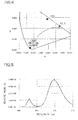
- Fig. 4 is a CIE chromaticity diagram.
- the CIE chromaticity diagram shows the example 6 as one example of phosphor according to the present invention.
- the black body locus is shown in the CIE chromaticity diagram.
- the color tone values x and y of the phosphors are measured in fluorescent radiation when an excitation light source of approximately 460 nm is used.
- the relative intensity of the phosphors represents comparison with (Y 0.8 Gd 0.2 ) 3 Al 5 O 12 :Ce.
- the color tone values x and y of the phosphor are measured in fluorescent radiation when an excitation light source of approximately 400 nm is used.
- the relative intensity of the phosphor represents comparison with SrAl 2 O 4 :Eu.
- the silicate group phosphor according to the example 1 has the composition of Sr 4.9 Eu 0.1 Si 2 O 9 .
- the silicate group phosphors according to the examples 2 to 11 have the composition (Sr, Ba) 4.9 Eu 0.1 Si 2 O 9 .
- the production method of the silicate group phosphor according to the example 6 is now described as an example of phosphor according to the present invention.
- the phosphors according to the examples 1 to 48 can be produced substantially similarly to this method.
- the above materials are measured, and are sufficiently mixed in a dry manner by a mixer.
- the mixed materials are placed in the crucible.
- the temperature in the is to 1200°C at a rate of 300°C/hr.
- the mixed material are burnt in a high temperature stage of 1200°C for 3 hours.
- the thus-obtained burnt material is pulverized, dispersed and sieved. Consequently, the target phosphor powder is obtained.
- the phosphors according to the examples 1 to 48 are produced substantially similarly to the phosphor according to the example 6.
- the silicate group phosphor according to the example 6 emits orange light.
- the relative light emission intensity of the silicate group phosphor according to the example 6 is 71.9% relative to the YAG group phosphor.
- the color tone values x and y of the CIE chromaticity diagram fall within ranges of 0.400 ⁇ x ⁇ 0.580 and 0.400 ⁇ y ⁇ 0.580 in fluorescent radiation.
- the color tone values x and y of the CIE chromaticity diagram fall within ranges of 0.530 ⁇ x ⁇ 0.580 and 0.420 ⁇ y ⁇ 0.470 in fluorescent radiation.
- the silicate group phosphors according to the examples 12 to 15 have the composition (Sr, Ba) 5-x Eu x Si 2 O 9 .
- the composition ratio of M 1 and x are changed.
- the measurement result of the silicate group phosphors according to the examples 12 to 15 is shown in the following table. [TABLE 2] Composition (Material) Body Color (After Treatment) Chromaticity Intensity (%) Sr Ba M 3 Eu Si x y Ex. 12 4.45 0.5 - 0.05 2 Orange 0.554 0.440 71.7 Ex. 13 4.3 0.5 - 0.2 2 Orange 0.553 0.440 59.5 Ex. 14 4.2 0.5 - 0.3 2 Orange 0.560 0.434 59.4 Ex. 15 4.1 0.5 - 0.4 2 Orange 0.556 0.438 48.1
- the silicate group phosphors according to the examples 16 to 19 have the composition of Sr 4.4 Ba 0.5 Eu 0.1 Si m O 2m+5 .
- the composition ratio of M 1 and m are changed.
- the measurement result of the silicate group phosphors according to the examples 16 to 19 is shown in the following table. [TABLE 3] Composition (Material) Body Color (After Treatment) Chromaticity Intensity (%) Sr Ba M 3 Eu Si x y Ex. 16 4.4 0.5 - 0.1 2.05 Orange 0.548 0.445 58.3 Ex.
- the silicate group phosphors according to the examples 20 to 27 have the composition (Sr, Ba) 4.9 Eu 0.15 Si 2 M 3 n O 9.075 . Pr, Nd, Dy, and Ho are used as M 3 .
- the measurement result of the silicate group phosphors according to the examples 20 to 23 is shown in the following table. [TABLE 4] Composition (Material) Body Color (After Treatment) Chromaticity Intensity (%) Sr Ba M 3 Eu Si x y Ref. Ex.
- the silicate group phosphors according to the examples 24 to 27 have the composition (Sr, Ba, Ca) 4.9 Eu 0.1 Si 2 O 9 .
- the composition ratio of M 1 is changed.
- the measurement result of the silicate group phosphors according to the examples 24 to 27 is shown in the following table. [TABLE 5] Composition (Material) Body Color (After Treatment) Chromaticity Intensity (%) Sr Ba Ca Eu Si x y Ex. 24 3.9 0.5 0.5 0.1 2 Deep Reddish Purple 0.453 0.530 33.4 Ex. 25 3.4 0.5 1 0.1 2 Reddish Deep Brown 0.470 0.516 36.7 Ex. 26 2.4 0.5 2 0.1 2 Ocher 0.499 0.490 43 Ex. 27 1.4 0.5 3 0.1 2 Ocher 0.513 0.476 38.2
- the silicate group phosphors according to the examples 29 and 30 have the composition of (Sr, Mg) 4.9 Eu 0.1 Si 2 O 9 .
- the composition ratio of M 1 is changed.
- the measurement result of the silicate group phosphors according to the examples 29 and 30 is shown in the following table. [TABLE 7] Composition (Material) Body Color (After Treatment) Chromaticity Intensity (%) Sr Ba Mg Eu Si x y Ex. 29 4.4 - 0.5 0.1 2 Yellow 0.473 0.514 44.8 Ex. 30 3.4 - 1.5 0.1 2 Yellow 0.417 0.555 50.1
- the silicate group phosphors according to the examples 31 to 41 have the composition of (Sr, Ca) 4.9 Eu 0.1 Si 2 O 9 .
- the composition ratio of M 1 is changed.
- the measurement result of the silicate group phosphors according to the examples 31 to 41 is shown in the following table. [TABLE 8] Composition (Material) Body Color (After Treatment) Chromaticity Intensity (%) Sr Ba Ca Eu Si x y Ex. 31 4.8 - 0.1 0.1 2 Reddish Purple 0.498 0.491 29.8 Ex.
- the silicate group phosphors according to the examples 42 to 45 have the composition of M 1 4.9 Eu 0.1 Si 2 O 9 .
- the composition ratio of M 1 is changed.
- the measurement result of the silicate group phosphors according to the examples 42 to 45 is shown in the following table. [TABLE 9] Composition (Material) Body Color (After Treatment) Chromaticity Intensity (%) Sr Ba Ca Eu Si x y Ex. 42 - 4.6 0.3 0.1 2 Purple Slightly Mixed with Brown Ex. 43 - 2.5 2.4 0.1 2 Light Ocher Ex. 44 - 0.3 4.6 0.1 2 Light Ocher 0.497 0.483 19.9 Ex. 45 - - 4.9 0.1 2 Light Ocher 0.460 0.490 5.5
- the silicate group phosphors according to the examples 46 to 48 have the composition of Sr 4.4 Ba 0.5 Eu 0.1 Si 2 B n O 9+(3/2)n .
- x 0.1
- the measurement result of the silicate group phosphors according to the examples 46 to 48 is shown in the following table. [TABLE 10] Composition (Material) Body Color (After Treatment) Chromaticity Intensity (%) Sr Ba M 3 Eu Si x y Ex. 46 4.4 0.5 B0.01 0.1 2 Yellow 0.545 0.448 50.1 Ex. 47 4.4 0.5 B0.03 0.1 2 Yellow 0.543 0.450 37.7 Ex. 48 4.4 0.5 B0.05 0.1 2 Yellow 0.545 0.448 31
- a silicate group phosphor according to a comparative example 1 has the composition of Sr 4.4 Ba 0.5 Eu 0.1 Si 3 O 11 .
- a silicate group phosphor according to a comparative example 2 has the composition of Sr 4.4 Ba 0.5 Eu 0.1 Si 2.5 O 10 .
- the measurement result of the silicate group phosphors according to the comparative examples 1 and 2 is shown in the following table. [TABLE 11] Composition (Material) Body Color (After Treatment) Chromaticity Intensity (%) Sr Ba M 3 Eu Si x y Comp. Ex. 1 4.4 0.5 - 0.1 3 Yellow Burnt Material 0.447 0.537 74.2 Comp. Ex. 2 4.4 0.5 - 0.1 2.5 Yellow Burnt Material 0.467 0.521 43.8
- Fig. 1 is a schematic cross sectional view showing the light emitting device according to the embodiment.
- Fig. 4 is a CIE chromaticity diagram.
- the CIE chromaticity diagram shows the phosphor according to the example 6 as one example of phosphor according to the present invention.
- Fig. 5 is a diagram showing the light emission spectrum of the light emitting device according to the example 49.
- Fig. 6 is a diagram showing the light emission spectra of the light emitting devices according to the examples 50 to 59.
- the light emitting device 10 includes the light emitting element 1 that has a light emission peak wavelength of approximately 460 nm, and the silicate group phosphor 2 according to the example 6 that has the composition of Sr 4.4 Ba 0.5 Eu 0.1 Si 2 O 9 .
- the chromaticity coordinates of the light emitting element 1 and the phosphor 2 are shown in the CIE chromaticity diagram.
- the illustrated light emitting device 10 according to the example 49 can be provided that emits amber color light.
- the light emitting devices 10 according to the examples 50 to 59 can be produced by adjustment of the amount of the phosphor 2 according to the example 6 that is provided in the cup portion 4a.
- the phosphor according to the example 59 contains a larger amount of the phosphor 2 than the phosphor according to the example 50.
- the phosphor according to the example 59 has a larger amount of reddish orange color component than the phosphor according to the example 50.
- Fig. 1 is a schematic cross sectional view showing the light emitting device according to the embodiment.
- Fig. 4 is a CIE chromaticity diagram.
- the CIE chromaticity diagram shows the phosphor according to the example 6 as an example of phosphor according to the present invention, and (Y 0.8 Gd 0.2 ) 3 Al 5 O 12 :Ce.
- Fig. 7 is a diagram showing the light emission spectrum of the light emitting device according to the example 60.
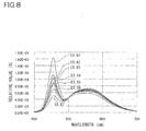
- Fig. 8 is a diagram showing the light emission spectra of the light emitting devices according to the examples 61 to 67.
- the light emitting device 10 includes the light emitting element 1 that has a light emission peak wavelength of approximately 460 nm, and the phosphor 2 that contains the silicate group phosphor 2 according to the example 6 that has the composition of Sr 4.4 Ba 0.5 Eu 0.1 Si 2 O 9 and a YAG phosphor that has the composition of (Y 0.8 Gd 0.2 ) 3 Al 5 O 12 :Ce.
- the chromaticity coordinates of the light emitting element 1 and the phosphor 2 are shown in the CIE chromaticity diagram.
- the illustrated light emitting device 10 according to the example 60 can be provided that emits white light in that a reddish orange color component is increased.
- the light emitting device 10 according to the example 60 has high color rendering.
- the light emitting devices 10 according to the examples 61 to 67 can be produced by adjustment of the amounts of the silicate group phosphor 2 and the YAG group phosphor that are provided in the cup portion 4a.
Landscapes
- Chemical & Material Sciences (AREA)
- Inorganic Chemistry (AREA)
- Engineering & Computer Science (AREA)
- Materials Engineering (AREA)
- Organic Chemistry (AREA)
- Luminescent Compositions (AREA)
Abstract
Description
- The present invention relates to a light emitting device that can be used for a signal light, a lighting device, a display, an indicator, various types of light sources and the like, and includes a phosphor. In particular, the present invention relates to a light emitting device that includes a phosphor that is excited by light emission spectrum from a light emitting element and can emit light in the visible range, and can emit white light, reddish orange light and the like.
- Various types of phosphors are known that emit light in a range from the ultraviolet range on the longer wavelength side to the visible light range on the shorter wavelength side. However, a phosphor is not known that has excellent light resistance, and effectively emits reddish orange light. As a phosphor that emits green light, a (Sr, Ca)S:Eu group phosphor is mainly used. However, the (Sr, Ca)S:Eu group phosphor has poor weather resistance and low light emission efficiency.
- As a silicate yellow group phosphor, which absorbs blue light that is emitted by a blue light-emitting diode and emits yellow range light different from the (Sr, Ca)S:Eu group phosphor, a silicate phosphor is known that is represented by the chemical formula of Sr2SiO4:Eu (see
Patent Document 1, for example).
Patent Document 1:Japanese Patent Laid-Open Publication No. 2005-277441 - However, known phosphors that emit reddish orange light do not have sufficient light emission efficiency if used for light sources in that displays and lighting devices are also included. It is required to improve the intensity and the mass-producibility of a phosphor that emits reddish orange light. In particular, a phosphor is not known that is excited by light in a range from the ultraviolet range on the longer wavelength side to the visible light range on the shorter wavelength side and can emit reddish orange light at sufficient intensity as compared with a Y3Al5O12:Ce phosphor (hereinafter, referred to as a "YAG group phosphor") and the like. For this reason, in order to provide reddish color tone light emission, the mixture ratio of a reddish orange phosphor is necessarily increased. In this case, the relative intensity of the light emission may decrease.
- Therefore, the present invention is aimed at providing a light emitting phosphor capable of emitting reddish orange light at high intensity, and a light emitting device using the phosphor.
- The inventors have diligently studied to solve the above problems, and as a result have solved the aforementioned problems and have developed the present invention.
- A phosphor according to the present invention absorbs light from an excitation light source in proximity to 460 nm and converts the wavelength of the light so that the color tone values x and y of the converted light fall within ranges 0.400 ≤ x ≤ 0.580 and 0.400 ≤ y ≤ 0.580 in the CIE chromaticity diagram. The phosphor includes at least one element selected from the group consisting of Mg, Ca, Sr, Ba and Zn, at least one element selected from the group consisting of Si, Ge and Sn, and an activator that contains at least Eu. Accordingly, it is possible to provide a high luminous phosphor that emits light in a predetermined color tone range. In particular, it is preferable that the phosphor is a silicate group phosphor that contains at least one element selected from the group consisting of Si, Ge and Sn, and essentially contains Si. It is because a phosphor with excellent weather resistance can be provided.
- A phosphor according to the present invention is represented by the general formula M1 5-xEuxM2 mM3 nO2m+(3/2)n+5 where x, m and n fall within ranges 0.0001 ≤ x ≤ 0.3, 1.0 ≤ m < 2.5 and 0 ≤ n < 2.5, M1 is at least one element selected from the group consisting of Mg, Ca, Sr, Ba and Zn, M2 is at least one element selected from the group consisting of Si, Ge and Sn, and M3 is at least one element selected from the group consisting of B, Al, Ga, In and rare earth elements. Accordingly, it is possible to provide a high luminous phosphor that emits reddish orange light or the like.
- A light emitting device according to the present invention includes a light emitting element that has a light emission peak wavelength in a range from 300 nm to 530 nm, and a phosphor that absorbs light from said light emitting element and converts the wavelength of the light to emit light with a light emission peak wavelength different from said light emitting element. The phosphor is represented by the general formula M1 5-xEuxM2 mM3 nO2m+(3/2)n+5 where x, m and n fall within ranges 0.0001 < x ≤ 0.3, 1.0 ≤ m < 2.5 and 0 ≤ n < 2.5, M1 is at least one element selected from the group consisting of Mg, Ca, Sr, Ba and Zn, M2 is at least one element selected from the group consisting of Si, Ge and Sn, and M3 is at least one element selected from the group consisting of B, Al, Ga, In and rare earth elements. Accordingly, it is possible to provide a light emitting device that can provide various types of light emission colors. Specifically, it is possible to provide a light emitting device that emits reddish orange range light, or a light emitting device that includes the phosphor in combination with a phosphor or the like that emits different color light to emit white range light.
- The configurations according to the present invention can provide a phosphor that has excellent in weather resistance, and can emit light at high intensity.
- The following description will describe an embodiment and examples of a phosphor and a light emitting device according to the present invention. However, the present invention is not limited to the embodiment and the examples.
- The following description will describe a phosphor according to the embodiment.
- A phosphor according to the present invention absorbs light from an excitation light source of 460 nm and converts the wavelength of the light so that the color tone values x and y of the converted light fall within ranges 0.400 ≤ x ≤ 0.580 and 0.400 ≤ y ≤ 0.580 in the CIE chromaticity diagram. The phosphor includes at least one element selected from the group consisting of Mg, Ca, Sr, Ba and Zn, at least one element selected from the group consisting of Si, Ge and Sn, and an activator that contains at least Eu.
- A phosphor according to the present invention is represented by the general formula M1 5-xEuxM2 mM3 nO2m+(3/2)n+5 where x, m and n fall within ranges 0.0001 ≤ x ≤ 0.3, 1.0 ≤ m < 2.5 and 0 < n < 2.5, M1 is at least one element selected from the group consisting of Mg, Ca, Sr, Ba and Zn, M2 is at least one element selected from the group consisting of Si, Ge and Sn, and M3 is at least one element selected from the group consisting of B, Al, Ga, In and rare earth elements.
- A silicate group phosphor that contains at least one element selected from the group consisting of Si, Ge and Sn, and essentially contains Si is described as the phosphor according to the present invention, however the present invention is not limited to this.
- The phosphor is represented by the general formula M1 5-xEuxM2 mM3 nO2m+(3/2)n+5 where x, m and n fall within ranges 0.0001 ≤ x ≤ 0.3, 1.0 ≤ m < 2.5 and 0 ≤ n < 2.5; M1 is at least one element selected from the group consisting of Mg, Ca, Sr, Ba and Zn; M2 is at least one element selected from the group consisting of Si, Ge and Sn, and essentially contains Si; and M3 is at least one element selected from the group consisting of B, Al, Ga, In and rare earth elements. In the case of n = 0, the phosphor is represented by M1 5-xEuxM2 mO2m+5. It is preferable that M1 contains at least one element selected from the group consisting of Mg, Ca, Sr, Ba and Zn, and essentially contains Sr. It is preferable that the rare earth group elements in M3 are Pr, Nd, Dy, and Ho. It is because the phosphor emits light at high intensity.
- The light excitation efficiency of the silicate group phosphor becomes low in a wavelength range longer than approximately 530 nm. Accordingly, the silicate group phosphor is efficiently excited by light in a wavelength range shorter than 530 nm. Also, the silicate group phosphor is efficiently excited by light in a wavelength range greater than 300 nm.
- hen excited, the silicate group phosphor emits light with light emission peak wavelength in a range from 550 to 630 nm. The light emission peak wavelength of the silicate group phosphor can be changed by variously changing the composition of the silicate group phosphor or by changing the excitation wavelength.
- The values x, m, and n of the composition of the silicate group phosphor fall within ranges of 0.0001 ≤ x ≤ 0.3, 1.0 < m < 2.5, and 0 ≤ n < 2.5. it is preferable that x falls within a range of 0.01 ≤ x ≤ 0.3. It is because this range can provide higher intensity. It is preferable that m falls within a range of 1.9 < m < 2.5. It is because this range can provide higher intensity. Phosphors with various color tones can be provided by changing n.
- The following description will describe a production method of a silicate phosphor Sr4.8Ba0.1Eu0.1Si2O9 according to the present invention. However, the present invention is not limited to this.
- SrCO3, BaCO3, SiO2, and Eu2O3 are first adjusted at a predetermined composition ratio, and are mixed. Compounds such as oxide, carbonate, nitride, imide compound and amide compound can also be used instead of SrCO3, BaCO3, SiO2, and Eu2O3. Also, flux such as SrF2 and BaF2 can be used, for example.
- Subsequently, the aforementioned materials are measured, and are sufficiently mixed in a dry manner by a mixer such as a ball mill.
- The material mixture is placed in a crucible, and is burnt in a reducing atmosphere. A tubular furnace, a box-shaped furnace, a high-frequency furnace, a metal furnace and the like can be used for burning. The burning is performed at burning temperature in a range from 1000° to 1600°C, however the burning temperature is not limited to this. A nitrogen-hydrogen atmosphere, a nitrogen atmosphere, an ammonia atmosphere, and an inert gas atmosphere such as argon can be used as the reducing atmosphere.
- The thus-obtained burnt material is pulverized, dispersed and sieved. Consequently, the target silicate group phosphor can be obtained.
- The following description will describe a light emitting device according to the embodiment.
Fig. 1 is a schematic cross sectional view showing the light emitting device according to the embodiment. - In a
light emitting device 10 according to the embodiment, alight emitting element 1 is arranged in acup portion 4a of alead frame 4. A sealingmember 3 is arranged in thecup portion 4a. Aphosphor 2 is mixed in the sealingmember 3. Thecup portion 4a and the sealingmember 3 are covered by amold sealing member 5. Thephosphor 2 contains at least the aforementioned silicate group phosphor. Thelead frame 4 is composed of a pair of, positive and negative terminal. The terminals are electrically connected to the positive and negative electrodes of thelight emitting element 1. - The
light emitting element 1 is an electroluminescent element that converts electric energy into light emission. Specifically, examples of the electroluminescent elements can be provided by a light emitting diode, a laser diode, a surface emission laser diode, an inorganic electroluminescence element, an organic electroluminescence element, and the like. In particular, from the viewpoint of high output of semiconductor light emitting elements, a light emitting diode or a surface emission laser diode is preferably used. Thelight emitting element 1 is not limited if the light emission peak wavelength of thelight emitting element 1 falls within a range from the ultraviolet range on the longer wavelength side to the visible light range on the shorter wavelength side. In particular, a light emitting element is preferably used that has a light emission peak wavelength in a range from 530 to 630 nm that excites the silicate group phosphor at high efficiency. - The
phosphor 2 may contain other phosphor than the silicate group phosphor. As for the other phosphor, it is preferable to use at least one material selected from an alkaline-earth halogen apatite phosphor, an alkaline-earth-metal boric-acid halogen phosphor, an alkaline-earth-metal aluminate phosphor, alkaline-earth silicate, alkaline-earth sulfide, rare-earth oxide sulfide, alkaline-earth thiogallate, alkaline-earth silicon nitride and germanate that are mainly activated by lanthanoid series such as Eu, or Mn; rare earth aluminate and rare earth silicate that are mainly activated by lanthanoid series such as Ce; and an organic material and organic complex that are mainly activated by lanthanoid series such as Eu. Specifically, the following phosphors can be used, however, the other phosphor is not limited to these phosphors. - An example of alkaline-earth halogen apatite phosphor that is mainly activated by a lanthanoid group element such as Eu or a transition metal group element such as Mn is provides by M5(PO4)3X:R (where is at least one element selected from the group consisting of Sr, Ca, Ba, Mg and Zn; X is at least one element selected from the group consisting of F, Cl, Br and I; and R is at least one selected from the group consisting of Eu, Mn, and combination of Eu and Mn) or the like.
- An example of alkaline-earth-metal boric-acid halogen phosphor is provided by M2B5O9X:R (where M is at least one element selected from the group consisting of Sr, Ca, Ba, Mg and Zn; X is at least one element selected from the group consisting of F, Cl, Br and I; and R is at least one selected from the group consisting of Eu, Mn, and combination of Eu and Mn) or the like.
- Examples of alkaline-earth-metal aluminate phosphors are provided by SrAl2O4:R, Sr4Al14O25:R, CaAl2O4:R, BaMg2Al16O27:R, and BaMgAl10O17:R (where R is at least one selected from the group consisting of Eu, Mn, and combination of Eu and Mn) and the like.
- Examples of rare-earth sulfide phosphors are provided by La2O2S:Eu, Y2O2S:Eu, Gd2O2S:Eu, and the like.
- Examples of rare earth aluminate phosphors that are mainly activated by a lanthanoid group element such as Ce are provided by YAG group phosphors that are represented by the composition formulas Y3Al5O12:Ce, (Y0.8Gd0.2)3Al5O12:Ce, Y3(Al0.8Ga0.2)5O12:Ce, (Y,Gd)3(Al, Ga)5O12, and the like.
- Additionally, examples of the other phosphors are provided by CaS:Eu, Zn2GeO4:Mn, and MGa2S4:Eu (where M is at least one element selected from the group consisting of Sr, Ca, Ba, Mg and Zn; and X is at least one element selected from the group consisting of F, Cl, Br and I) and the like. Also, examples of the other phosphors are provided by M2Si5N8:Eu, MSi7N10:Eu, M1.8Si5O0.2N8:Eu, and M0.9Si7O0.1N10:Eu (where M is at least one element selected from the group consisting of Sr, Ca, Ba, Mg and Zn) and the like.
- The aforementioned second examples of the other phosphors may contain at least one element selected the group consisting of Tb, Cu, Ag, Au, Cr, Nd, Dy, Co, Ni, Ti and the like in stead of Eu, or in addition to Eu, if desired.
- Also, a phosphor other than the aforementioned phosphors can be used that has similar performance and effects
- These phosphors can be used as a phosphor that has a yellow, red, green or blue range emission spectrum of light that is excited by excitation light from the
light emitting element 1, or has an intermediate color emission spectrum that lies between the yellow, red, green and blue ranges such as yellow and bluish green. ln the case where these phosphors are used in combination with the silicate group phosphor, it is possible to provide light emitting devices with various light emission colors. - For example, in the case where the
light emitting device 10 includes a light emitting element that emits blue light, and thesilicate group phosphor 2 that emits reddish orange range light, it is possible to provide a light emitting device that emits amber color light. - Also, for example, in the case where the
light emitting device 10 includes a light emitting element that emits blue light, a YAG group phosphor that emits yellowish green range light, and thesilicate group phosphor 2 that emits reddish orange range light, it is possible to provide a light emitting device that emits white light with good color rendering. Accordingly, it is possible to provide a desired white light with a broad light emission spectrum. - It is preferable that an excellent heat and light resistance material is used for the sealing
member 3. For example, an epoxy resin, a silicone resin, a urea resin or the like can be used. The sealingmember 3 can contain a diffusion material, a coloring material, and an ultraviolet ray absorbing material. - The
mold sealing member 5 is arranged to protect thelight emitting element 1, wire lines, and a part of thelead frame 4. Themold sealing member 5 can have a convex or concave lens shape, and may have a multi-layer structure. Specifically, transparent resin with excellent transparency, weather resistance and temperature characteristics such as an epoxy resin, an urea resin and silicone resin, silica sol, glass, or the like can be used as the material of themold sealing member 5. Themold sealing member 5 can include a diffusion material, a coloring material, an ultraviolet absorbing material, and a phosphor. - The following description will describe phosphors and light emitting devices according to examples of the present invention in more detail.
Fig. 2 is a diagram showing the excitation spectra of silicate group phosphors according to examples 1 and 6.Fig. 3 is a diagram showing the light emission spectra of the silicate group phosphors according to the examples 1 and 6.Fig. 4 is a CIE chromaticity diagram. The CIE chromaticity diagram shows the example 6 as one example of phosphor according to the present invention. The black body locus is shown in the CIE chromaticity diagram. The general formula of the silicate group phosphor is represented by M1 5-xEuxM2 mM3 nO2m+(3/2)n+5 where x, m and n fall within ranges 0.0001 ≤ x ≤ 0.3, 1.0 ≤ m < 2.5 and 0 ≤ n < 2.5, M1 is at least one element selected from the group consisting of Mg, Ca, Sr, Ba and Zn, M2 is at least one element selected from the group consisting of Si, Ge and Sn, and M3 is at least one element selected from the group consisting of B, Al, Ga, In and rare earth elements. All of silicate group phosphors according to examples 1 to 48 fall within the composition range. The following tables show the composition of the silicate group phosphors according to the examples 1 to 48 before burning. - In the examples 1 to 10 and 12 to 48, the color tone values x and y of the phosphors are measured in fluorescent radiation when an excitation light source of approximately 460 nm is used. The relative intensity of the phosphors represents comparison with (Y0.8Gd0.2)3Al5O12:Ce.
- In the example 11, the color tone values x and y of the phosphor are measured in fluorescent radiation when an excitation light source of approximately 400 nm is used. The relative intensity of the phosphor represents comparison with SrAl2O4:Eu.
- The silicate group phosphor according to the example 1 has the composition of Sr4.9Eu0.1Si2O9. The silicate group phosphors according to the examples 2 to 11 have the composition (Sr, Ba)4.9Eu0.1Si2O9. The composition ratio between Sr and Ba is shown in the following table. In the silicate group phosphors according to the examples 1 to 11, in the case of x = 0.1, m = 2 and n = 0, the composition ratio of M1 is changed.
- The measurement result of the silicate group phosphors according to the examples 1 to 11 is shown in the following table.
[TABLE 1] Composition (Material) Body Color (After Treatment) Chromaticity Intensity (%) Sr Ba M3 Eu Si x y Ex. 1 4.9 0 - 0.1 2 Yellowish Orange 0.516 0.478 69.2 Ex. 2 4.8 0.1 - 0.1 2 Orange 0.533 0.461 78.6 Ex. 3 4.7 0.2 - 0.1 2 Orange 0.542 0.453 76.3 Ex. 4 4.6 0.3 - 0.1 2 Orange 0.544 0.450 71.2 Ex. 5 4.5 0.4 - 0.1 2 Orange 0.552 0.443 74.9 Ex. 6 4.4 0.5 - 0.1 2 Orange 0.555 0.439 71.9 Ex. 7 4.3 0.6 - 0.1 2 Orange 0.558 0.435 76 Ex. 8 4.2 0.7 - 0.1 2 Orange 0.561 0.433 70.4 Ex. 9 4.1 0.8 - 0.1 2 Orange 0.543 0.449 48.3 Ex. 10 3.9 1 - 0.1 2 Light Orange 0.548 0.445 25.5 Ex. 11 2.4 2.5 - 0.1 2 Yellowish Green by 400 nm 0.271 0.598 36.8 - The production method of the silicate group phosphor according to the example 6 is now described as an example of phosphor according to the present invention. The phosphors according to the examples 1 to 48 can be produced substantially similarly to this method.
- SrCO3, BaCO3, SiO2 and Eu2O3 are prepared as materials, and SrF2 is prepared as flux. They are adjusted to provide the composition ratio of Sr4.4Ba0.5Eu0.1Si2O9 and are mixed.
SrCO3 129.9g BaCO3 19.7g SiO2 24.0g Eu2O3 3.52g SrF2 0.62g - The above materials are measured, and are sufficiently mixed in a dry manner by a mixer. The mixed materials are placed in the crucible. The temperature in the is to 1200°C at a rate of 300°C/hr. The mixed material are burnt in a high temperature stage of 1200°C for 3 hours. The thus-obtained burnt material is pulverized, dispersed and sieved. Consequently, the target phosphor powder is obtained. The phosphors according to the examples 1 to 48 are produced substantially similarly to the phosphor according to the example 6.
- In the case where an excitation light source 460 nm is used, the silicate group phosphor according to the example 6 emits orange light. The relative light emission intensity of the silicate group phosphor according to the example 6 is 71.9% relative to the YAG group phosphor.
- In all of the phosphors according to the examples 1 to 10 and 12 to 48, the color tone values x and y of the CIE chromaticity diagram fall within ranges of 0.400 ≤ x ≤ 0.580 and 0.400 < y ≤ 0.580 in fluorescent radiation. In particular, in the phosphors according to the examples 2 to 10 and 12 to 23, the color tone values x and y of the CIE chromaticity diagram fall within ranges of 0.530 ≤ x ≤ 0.580 and 0.420 < y ≤ 0.470 in fluorescent radiation.
- The silicate group phosphors according to the examples 12 to 15 have the composition (Sr, Ba)5-xEuxSi2O9. In the silicate group phosphors according to the examples 12 to 15, in the case of m = 2 and n = 0, the composition ratio of M1 and x are changed. The measurement result of the silicate group phosphors according to the examples 12 to 15 is shown in the following table.
[TABLE 2] Composition (Material) Body Color (After Treatment) Chromaticity Intensity (%) Sr Ba M3 Eu Si x y Ex. 12 4.45 0.5 - 0.05 2 Orange 0.554 0.440 71.7 Ex. 13 4.3 0.5 - 0.2 2 Orange 0.553 0.440 59.5 Ex. 14 4.2 0.5 - 0.3 2 Orange 0.560 0.434 59.4 Ex. 15 4.1 0.5 - 0.4 2 Orange 0.556 0.438 48.1 - The silicate group phosphors according to the examples 16 to 19 have the composition of Sr4.4Ba0.5Eu0.1SimO2m+5. In the silicate group phosphors according to the examples 16 to 19, in the case of x = 0.1, m = 0 and n = 0, the composition ratio of M1 and m are changed. The measurement result of the silicate group phosphors according to the examples 16 to 19 is shown in the following table.
[TABLE 3] Composition (Material) Body Color (After Treatment) Chromaticity Intensity (%) Sr Ba M3 Eu Si x y Ex. 16 4.4 0.5 - 0.1 2.05 Orange 0.548 0.445 58.3 Ex. 17 4.4 0.5 - 0.1 2.1 Orange 0.548 0.446 59.4 Ex. 18 4.4 0.5 - 0.1 1.95 Orange 0.552 0.442 56.8 Ex. 19 4.4 0.5 - 0.1 1.9 Orange 0.552 0.442 55.3 - The silicate group phosphors according to the examples 20 to 27 have the composition (Sr, Ba)4.9Eu0.15Si2M3 nO9.075. Pr, Nd, Dy, and Ho are used as M3. In the silicate group phosphors according to the examples 20 to 23, in the case of x = 0.1, m = 2 and n = 0.05, the element of M3 is changed. The measurement result of the silicate group phosphors according to the examples 20 to 23 is shown in the following table.
[TABLE 4] Composition (Material) Body Color (After Treatment) Chromaticity Intensity (%) Sr Ba M3 Eu Si x y Ref. Ex. 1 4.35 0.5 - Mn0.05 0.1 2 Ocher Burnt Material Partially with Purple Ref. Ex. 2 4.3 0.5 - Mn0.1 0.1 2 Ocher Burnt Material Partially with Purple Ex. 20 4.4 0.5 Pr0.05 - 0.1 2 Orange 0.543 0.450 47.5 Ex. 21 4.4 0.5 Nd0.05 - 0.1 2 Orange 0.541 0.451 46.7 Ex. 22 4.4 0.5 Dy0.05 - 0.1 2 Orange 0.543 0.450 50.2 Ex. 23 4.4 0.5 Ho0.05 - 0.1 2 Orange 0.544 0.449 51.2 - The silicate group phosphors according to the examples 24 to 27 have the composition (Sr, Ba, Ca)4.9Eu0.1Si2O9. In the silicate group phosphors according to the examples 20 to 27, in the case of x = 0.1, m = 2 and n = 0, the composition ratio of M1 is changed. The measurement result of the silicate group phosphors according to the examples 24 to 27 is shown in the following table.
[TABLE 5] Composition (Material) Body Color (After Treatment) Chromaticity Intensity (%) Sr Ba Ca Eu Si x y Ex. 24 3.9 0.5 0.5 0.1 2 Deep Reddish Purple 0.453 0.530 33.4 Ex. 25 3.4 0.5 1 0.1 2 Reddish Deep Brown 0.470 0.516 36.7 Ex. 26 2.4 0.5 2 0.1 2 Ocher 0.499 0.490 43 Ex. 27 1.4 0.5 3 0.1 2 Ocher 0.513 0.476 38.2 - The silicate group phosphor according to the example 28 has the composition of Sr4.4Ba0.5Eu0.1SimAlnO2m+(3/2)n+5. In the silicate group phosphor according to the example 28, in the case of x = 0.1, M3 = Al, m and n are changed. The measurement result of the silicate group phosphors according to the example 28 is shown in the following table.
[TABLE 6] Composition (Material) Body Color (After Treatment) Chromaticity Intensity (%) Sr Ba M3 Eu Si x y Ref. Ex. 3 4.4 0.5 Al1 0.1 1 Gray Ref. Ex. 4 4.4 0.5 Al0.2 0.1 1.8 Ocher Ex. 28 4.4 0.5 Al2 0.1 2 Light Yellow 0.455 0.527 17.1 Ref. Ex. 5 4.4 0.5 Al0.5 0.1 0.5 Melted State. Purple. - The silicate group phosphors according to the examples 29 and 30 have the composition of (Sr, Mg)4.9Eu0.1Si2O9. In the silicate group phosphors according to the examples 29 and 30, in the case of x = 0.1, m = 2 and n = 0, the composition ratio of M1 is changed. The measurement result of the silicate group phosphors according to the examples 29 and 30 is shown in the following table.
[TABLE 7] Composition (Material) Body Color (After Treatment) Chromaticity Intensity (%) Sr Ba Mg Eu Si x y Ex. 29 4.4 - 0.5 0.1 2 Yellow 0.473 0.514 44.8 Ex. 30 3.4 - 1.5 0.1 2 Yellow 0.417 0.555 50.1 - The silicate group phosphors according to the examples 31 to 41 have the composition of (Sr, Ca)4.9Eu0.1Si2O9. In the silicate group phosphors according to the examples 31 to 41, in the case of x = 0.1, m = 2 and n = 0, the composition ratio of M1 is changed. The measurement result of the silicate group phosphors according to the examples 31 to 41 is shown in the following table.
[TABLE 8] Composition (Material) Body Color (After Treatment) Chromaticity Intensity (%) Sr Ba Ca Eu Si x y Ex. 31 4.8 - 0.1 0.1 2 Reddish Purple 0.498 0.491 29.8 Ex. 32 4.6 - 0.3 0.1 2 Reddish Purple 0.502 0.488 27.9 Ex. 33 4.4 - 0.5 0.1 2 Reddish Purple 0.502 0.487 27.9 Ex. 34 4.2 - 0.7 0.1 2 Reddish Purple 0.507 0.483 33.6 Ex. 35 3.9 - 1 0.1 2 Reddish Brown 0.515 0.476 39.5 Ex. 36 3.4 - 1.5 0.1 2 Light Brown 0.530 0.462 33 Ex. 37 2.9 - 2 0.1 2 Light Brown 0.546 0.446 29.2 Ex. 38 2.5 - 2.4 0.1 2 Light Brown 0.551 0.440 32.8 Ex. 39 1.9 - 3 0.1 2 Light Brown 0.547 0.441 22.8 Ex. 40 1.4 - 3.5 0.1 2 Light Brown 0.536 0.449 20.6 Ex. 41 0.3 - 4.6 0.1 2 Light Ocher 0.475 0.490 8 - The silicate group phosphors according to the examples 42 to 45 have the composition of M1 4.9Eu0.1Si2O9. In the silicate group phosphors according to the examples 42 to 45, in the case of x = 0.1, m = 2 and n = 0, the composition ratio of M1 is changed. The measurement result of the silicate group phosphors according to the examples 42 to 45 is shown in the following table.
[TABLE 9] Composition (Material) Body Color (After Treatment) Chromaticity Intensity (%) Sr Ba Ca Eu Si x y Ex. 42 - 4.6 0.3 0.1 2 Purple Slightly Mixed with Brown Ex. 43 - 2.5 2.4 0.1 2 Light Ocher Ex. 44 - 0.3 4.6 0.1 2 Light Ocher 0.497 0.483 19.9 Ex. 45 - - 4.9 0.1 2 Light Ocher 0.460 0.490 5.5 - The silicate group phosphors according to the examples 46 to 48 have the composition of Sr4.4Ba0.5Eu0.1Si2BnO9+(3/2)n. In the silicate group phosphors according to the examples 46 to 48, in the case of x = 0.1, m = 2 and M3 = B, n is changed. The measurement result of the silicate group phosphors according to the examples 46 to 48 is shown in the following table.
[TABLE 10] Composition (Material) Body Color (After Treatment) Chromaticity Intensity (%) Sr Ba M3 Eu Si x y Ex. 46 4.4 0.5 B0.01 0.1 2 Yellow 0.545 0.448 50.1 Ex. 47 4.4 0.5 B0.03 0.1 2 Yellow 0.543 0.450 37.7 Ex. 48 4.4 0.5 B0.05 0.1 2 Yellow 0.545 0.448 31 - A silicate group phosphor according to a comparative example 1 has the composition of Sr4.4Ba0.5Eu0.1Si3O11. A silicate group phosphor according to a comparative example 2 has the composition of Sr4.4Ba0.5Eu0.1Si2.5O10. In the silicate group phosphors according to the comparative examples 1 and 2, x, m and n are set as x = 0.1, m = 3 or 2.5, and n = 0. The measurement result of the silicate group phosphors according to the comparative examples 1 and 2 is shown in the following table.
[TABLE 11] Composition (Material) Body Color (After Treatment) Chromaticity Intensity (%) Sr Ba M3 Eu Si x y Comp. Ex. 1 4.4 0.5 - 0.1 3 Yellow Burnt Material 0.447 0.537 74.2 Comp. Ex. 2 4.4 0.5 - 0.1 2.5 Yellow Burnt Material 0.467 0.521 43.8 - Light emitting devices according to examples 49 to 59 are described.
Fig. 1 is a schematic cross sectional view showing the light emitting device according to the embodiment.Fig. 4 is a CIE chromaticity diagram. The CIE chromaticity diagram shows the phosphor according to the example 6 as one example of phosphor according to the present invention.Fig. 5 is a diagram showing the light emission spectrum of the light emitting device according to the example 49.Fig. 6 is a diagram showing the light emission spectra of the light emitting devices according to the examples 50 to 59. - The
light emitting device 10 includes thelight emitting element 1 that has a light emission peak wavelength of approximately 460 nm, and thesilicate group phosphor 2 according to the example 6 that has the composition of Sr4.4Ba0.5Eu0.1Si2O9. The chromaticity coordinates of thelight emitting element 1 and thephosphor 2 are shown in the CIE chromaticity diagram. Thelight emitting element 1 has the chromaticity coordinates of x = 0.149, and y = 0.032. When thephosphor 2 is excited by thelight emitting element 1 that has a light emission peak wavelength of approximately 460 nm, the chromaticity coordinates x and y of thephosphor 2 are x = 0.560, and y = 0.430. - The illustrated
light emitting device 10 according to the example 49 can be provided that emits amber color light. Also, thelight emitting devices 10 according to the examples 50 to 59 can be produced by adjustment of the amount of thephosphor 2 according to the example 6 that is provided in thecup portion 4a. The phosphor according to the example 59 contains a larger amount of thephosphor 2 than the phosphor according to the example 50. Also, the phosphor according to the example 59 has a larger amount of reddish orange color component than the phosphor according to the example 50. Thelight emitting devices 10 according to the examples 49 to 59 have chromaticity that is located in proximity to the straight line that connects the chromaticity of thelight emitting element 1 and the chromaticity of thephosphor 2 according to the example 6 in the CIE chromaticity diagram. - Light emitting devices according to examples 60 to 67 are described.
Fig. 1 is a schematic cross sectional view showing the light emitting device according to the embodiment.Fig. 4 is a CIE chromaticity diagram. The CIE chromaticity diagram shows the phosphor according to the example 6 as an example of phosphor according to the present invention, and (Y0.8Gd0.2)3Al5O12:Ce.Fig. 7 is a diagram showing the light emission spectrum of the light emitting device according to the example 60.Fig. 8 is a diagram showing the light emission spectra of the light emitting devices according to the examples 61 to 67. - The
light emitting device 10 includes thelight emitting element 1 that has a light emission peak wavelength of approximately 460 nm, and thephosphor 2 that contains thesilicate group phosphor 2 according to the example 6 that has the composition of Sr4.4Ba0.5Eu0.1Si2O9 and a YAG phosphor that has the composition of (Y0.8Gd0.2)3Al5O12:Ce. The chromaticity coordinates of thelight emitting element 1 and thephosphor 2 are shown in the CIE chromaticity diagram. Thelight emitting element 1 has the chromaticity coordinates of x = 0.149, and y = 0.032. When the silicate group phosphor is excited by thelight emitting element 1 that has a light emission peak wavelength of approximately 460 nm, the chromaticity coordinates x and y of the silicate group phosphor are x = 0.560, and y = 0.430. When the YAG phosphor is excited by thelight emitting element 1 that has a light emission peak wavelength of approximately 460 nm, the chromaticity coordinates x and y of the YAG phosphor are x = 0.384, and y = 0.572. - The illustrated
light emitting device 10 according to the example 60 can be provided that emits white light in that a reddish orange color component is increased. Thelight emitting device 10 according to the example 60 has high color rendering. Also, thelight emitting devices 10 according to the examples 61 to 67 can be produced by adjustment of the amounts of thesilicate group phosphor 2 and the YAG group phosphor that are provided in thecup portion 4a. - The
light emitting devices 10 according to the examples 61 to 67 have chromaticity that is located in proximity to the interior of a triangle that is defined by the chromaticity of thelight emitting element 1, the chromaticity of the silicate group phosphor, and the chromaticity of the YAG phosphor in the CIE chromaticity diagram. - A light emitting device according to the present invention can be used for a signal light, a lighting device, a display, an indicator, various types of light sources and the like, and can be used as a light emitting device that includes a phosphor.
-
-
Fig. 1 is a schematic cross sectional view showing a light emitting device according to an embodiment; -
Fig. 2 is a diagram showing the excitation spectra of silicate group phosphors according to examples 1 and 6; -
Fig. 3 is a diagram showing the light emission spectra of the silicate group phosphors according to the examples 1 and 6; -
Fig. 4 is a CIE chromaticity diagram; -
Fig. 5 is a diagram showing the light emission spectrum of a light emitting device according to an example 49; -
Fig. 6 is a diagram showing the light emission spectra of light emitting devices according to examples 50 to 59; -
Fig. 7 is a diagram showing the light emission spectrum of a light emitting device according to an example 60; and -
Fig. 8 is a diagram showing the light emission spectra of light emitting devices according to examples 61 to 67. -
- 1
- Light Emitting Element
- 2
- Phosphor
- 3
- Sealing Member
- 4
- Lead Frame
- 5
- Mold Sealing Member
- 10
- Light Emitting Device
Claims (3)
- A phosphor that absorbs light from an excitation light source in proximity to 460 nm and converts the wavelength of the light so that the color tone values x and y of the converted light fall within ranges 0.400 ≤ x ≤ 0.580 and 0.400 ≤ y ≤ 0.580 in the CIE chromaticity diagram, the phosphor comprising at least one element selected from the group consisting of Mg, Ca, Sr, Ba and Zn, at least one element selected from the group consisting of Si, Ge and Sn, and an activator that contains at least Eu.
- A phosphor that is represented by the general formula M1 5-xEuxM2 mM3 nO2m+(3/2)n+5 where x, m and n fall within ranges 0.0001 ≤ x ≤ 0.3, 1.0 ≤ m < 2.5 and 0 ≤ n < 2.5, M1 is at least one element selected from the group consisting of Mg, Ca, Sr, Ba and Zn, M2 is at least one element selected from the group consisting of Si, Ge and Sn, and M3 is at least one element selected from the group consisting of B, Al, Ga, In and rare earth elements.
- A light emitting device comprising:a light emitting element that has a light emission peak wavelength in a range from 300 nm to 530 nm; anda phosphor that absorbs light from said light emitting element and converts the wavelength of the light to emit light with a light emission peak wavelength different from said light emitting element, wherein the phosphor is represented by the general formula M1 5-xEuxM2 mM3 nO2m+(3/2)n+5 where x, m and n fall within ranges 0.0001 ≤ x ≤ 0.3, 1.0 ≤ m < 2.5 and 0 < n < 2.5, M1 is at least one element selected from the group consisting of Mg, Ca, Sr, Ba and Zn, M2 is at least one element selected from the group consisting of Si, Ge and Sn, and M3 is at least one element selected from the group consisting of B, Al, Ga, In and rare earth elements.
Applications Claiming Priority (2)
| Application Number | Priority Date | Filing Date | Title |
|---|---|---|---|
| JP2005226089 | 2005-08-04 | ||
| PCT/JP2006/315391 WO2007015542A1 (en) | 2005-08-04 | 2006-08-03 | Phosphor and light-emitting device |
Publications (3)
| Publication Number | Publication Date |
|---|---|
| EP1911826A1 true EP1911826A1 (en) | 2008-04-16 |
| EP1911826A4 EP1911826A4 (en) | 2008-08-13 |
| EP1911826B1 EP1911826B1 (en) | 2009-12-16 |
Family
ID=37708822
Family Applications (1)
| Application Number | Title | Priority Date | Filing Date |
|---|---|---|---|
| EP06782251A Active EP1911826B1 (en) | 2005-08-04 | 2006-08-03 | Phosphor and light-emitting device |
Country Status (5)
| Country | Link |
|---|---|
| US (1) | US7927512B2 (en) |
| EP (1) | EP1911826B1 (en) |
| JP (1) | JP4873183B2 (en) |
| DE (1) | DE602006011168D1 (en) |
| WO (1) | WO2007015542A1 (en) |
Cited By (8)
| Publication number | Priority date | Publication date | Assignee | Title |
|---|---|---|---|---|
| KR101047775B1 (en) | 2008-09-23 | 2011-07-07 | 주식회사 포스포 | Phosphor and Light Emitting Device |
| US8598618B2 (en) | 2008-04-17 | 2013-12-03 | Kabushiki Kaisha Toshiba | White light emitting device, backlight, liquid crystal display device, and illuminating device |
| WO2015060701A1 (en) * | 2013-10-22 | 2015-04-30 | Vilnius University | Photobiologically friendly phosphor converted light-emitting diode |
| US9611987B2 (en) | 2008-08-05 | 2017-04-04 | The Regents Of The University Of California | White light source employing a III-nitride based laser diode pumping a phosphor |
| CN106554774A (en) * | 2015-09-24 | 2017-04-05 | 晶元光电股份有限公司 | Fluorescent material and preparation method thereof |
| CN107474353A (en) * | 2017-06-26 | 2017-12-15 | 浙江转喆科技有限公司 | A kind of conversion film and preparation method thereof |
| CN107488449A (en) * | 2017-06-26 | 2017-12-19 | 浙江转喆科技有限公司 | Lower conversion light conversion agent and preparation method thereof and lower transformation of blue conversion film and preparation method thereof |
| US10008641B2 (en) | 2012-11-16 | 2018-06-26 | Lg Innotek Co., Ltd. | Phosphor composition and light emitting device package having the same |
Families Citing this family (9)
| Publication number | Priority date | Publication date | Assignee | Title |
|---|---|---|---|---|
| JP4770319B2 (en) * | 2005-08-04 | 2011-09-14 | 日亜化学工業株式会社 | Phosphor and light emitting device |
| EP2052052B1 (en) * | 2006-12-29 | 2011-10-05 | LG Innotek Co., Ltd. | Phosphor material, coating phosphor composition, method of preparing phosphor material and light emitting device |
| US20110012141A1 (en) * | 2009-07-15 | 2011-01-20 | Le Toquin Ronan P | Single-color wavelength-converted light emitting devices |
| CN103254895B (en) * | 2013-05-12 | 2014-09-24 | 吉林大学 | Aluminosilicate green fluorescent powder and preparation method thereof |
| US10283681B2 (en) | 2013-09-12 | 2019-05-07 | Cree, Inc. | Phosphor-converted light emitting device |
| CN106811195A (en) * | 2017-01-18 | 2017-06-09 | 厦门科煜光电有限公司 | A kind of novel silicon phosphate compounds luminescent material |
| CN106811196A (en) * | 2017-01-18 | 2017-06-09 | 厦门科煜光电有限公司 | A kind of preparation method of novel silicon phosphate compounds luminescent material |
| US20200251622A1 (en) * | 2019-02-06 | 2020-08-06 | Osram Opto Semiconductors Gmbh | Conversion Element, Radiation-Emitting Semiconductor Device and Method for Producing a Conversion Element |
| JP7534642B2 (en) | 2021-04-26 | 2024-08-15 | 日亜化学工業株式会社 | Light-emitting devices, lighting fixtures and street lights |
Family Cites Families (11)
| Publication number | Priority date | Publication date | Assignee | Title |
|---|---|---|---|---|
| US5839718A (en) * | 1997-07-22 | 1998-11-24 | Usr Optonix Inc. | Long persistent phosphorescence phosphor |
| EP1104799A1 (en) * | 1999-11-30 | 2001-06-06 | Patent-Treuhand-Gesellschaft für elektrische Glühlampen mbH | Red emitting luminescent material |
| AT410266B (en) * | 2000-12-28 | 2003-03-25 | Tridonic Optoelectronics Gmbh | LIGHT SOURCE WITH A LIGHT-EMITTING ELEMENT |
| JP3756930B2 (en) | 2001-09-03 | 2006-03-22 | 松下電器産業株式会社 | Manufacturing method of semiconductor light emitting device |
| WO2003021691A1 (en) * | 2001-09-03 | 2003-03-13 | Matsushita Electric Industrial Co., Ltd. | Semiconductor light emitting device, light emitting apparatus and production method for semiconductor light emitting device |
| JP2004115633A (en) * | 2002-09-25 | 2004-04-15 | Matsushita Electric Ind Co Ltd | Silicate phosphor and light emitting device using the same |
| FR2846663B1 (en) | 2002-11-05 | 2006-08-11 | Rhodia Elect & Catalysis | LIGHT-EMITTING MATERIAL, PARTICULARLY FOR GREENHOUSE WALLS, COMPRISING AS A BARIUM AND MAGNESIUM SILICATE ADDITIVE |
| DE10259946A1 (en) * | 2002-12-20 | 2004-07-15 | Tews, Walter, Dipl.-Chem. Dr.rer.nat.habil. | Phosphors for converting the ultraviolet or blue emission of a light-emitting element into visible white radiation with very high color rendering |
| DE10259949A1 (en) * | 2002-12-20 | 2004-07-01 | Robert Bosch Gmbh | piezo actuator |
| WO2004085570A1 (en) | 2003-03-28 | 2004-10-07 | Korea Research Institute Of Chemical Technology | Strontium silicate-based phosphor, fabrication method thereof, and led using the phosphor |
| US6982045B2 (en) * | 2003-05-17 | 2006-01-03 | Phosphortech Corporation | Light emitting device having silicate fluorescent phosphor |
-
2006
- 2006-08-03 DE DE602006011168T patent/DE602006011168D1/en active Active
- 2006-08-03 US US11/997,807 patent/US7927512B2/en not_active Expired - Fee Related
- 2006-08-03 WO PCT/JP2006/315391 patent/WO2007015542A1/en not_active Ceased
- 2006-08-03 JP JP2007529526A patent/JP4873183B2/en not_active Expired - Fee Related
- 2006-08-03 EP EP06782251A patent/EP1911826B1/en active Active
Cited By (8)
| Publication number | Priority date | Publication date | Assignee | Title |
|---|---|---|---|---|
| US8598618B2 (en) | 2008-04-17 | 2013-12-03 | Kabushiki Kaisha Toshiba | White light emitting device, backlight, liquid crystal display device, and illuminating device |
| US9611987B2 (en) | 2008-08-05 | 2017-04-04 | The Regents Of The University Of California | White light source employing a III-nitride based laser diode pumping a phosphor |
| KR101047775B1 (en) | 2008-09-23 | 2011-07-07 | 주식회사 포스포 | Phosphor and Light Emitting Device |
| US10008641B2 (en) | 2012-11-16 | 2018-06-26 | Lg Innotek Co., Ltd. | Phosphor composition and light emitting device package having the same |
| WO2015060701A1 (en) * | 2013-10-22 | 2015-04-30 | Vilnius University | Photobiologically friendly phosphor converted light-emitting diode |
| CN106554774A (en) * | 2015-09-24 | 2017-04-05 | 晶元光电股份有限公司 | Fluorescent material and preparation method thereof |
| CN107474353A (en) * | 2017-06-26 | 2017-12-15 | 浙江转喆科技有限公司 | A kind of conversion film and preparation method thereof |
| CN107488449A (en) * | 2017-06-26 | 2017-12-19 | 浙江转喆科技有限公司 | Lower conversion light conversion agent and preparation method thereof and lower transformation of blue conversion film and preparation method thereof |
Also Published As
| Publication number | Publication date |
|---|---|
| US7927512B2 (en) | 2011-04-19 |
| US20100219746A1 (en) | 2010-09-02 |
| EP1911826B1 (en) | 2009-12-16 |
| JPWO2007015542A1 (en) | 2009-02-19 |
| JP4873183B2 (en) | 2012-02-08 |
| DE602006011168D1 (en) | 2010-01-28 |
| EP1911826A4 (en) | 2008-08-13 |
| WO2007015542A1 (en) | 2007-02-08 |
Similar Documents
| Publication | Publication Date | Title |
|---|---|---|
| US7094362B2 (en) | Garnet phosphor materials having enhanced spectral characteristics | |
| CN100530708C (en) | Phosphor for LED and mixture thereof | |
| EP1911826B1 (en) | Phosphor and light-emitting device | |
| EP1859657B1 (en) | Illumination system comprising a radiation source and a fluorescent material | |
| US7026755B2 (en) | Deep red phosphor for general illumination applications | |
| JP3763719B2 (en) | Phosphors based on oxynitride glass | |
| CN101194375B (en) | Light emitting device | |
| EP1574558B1 (en) | Phosphor and optical device using same | |
| EP2760970B1 (en) | Phosphor materials and related devices | |
| US7252787B2 (en) | Garnet phosphor materials having enhanced spectral characteristics | |
| EP1837386A1 (en) | Nitride phosphor, method for producing same and light-emitting device using nitride phosphor | |
| EP2067840B1 (en) | Fluorescent substance, fluorescent sheets, process for production of the fluorescent substance, and light-emitting devices made by using the substance | |
| US20060208270A1 (en) | Borate phosphor materials for use in lighting applications | |
| US20060071589A1 (en) | White lamps with enhanced color contrast | |
| US20080203892A1 (en) | Illumination System Comprising a Radiation Source and a Luminescent Material | |
| CN101180381A (en) | Red phosphors for LED-based lighting | |
| KR100666211B1 (en) | Silicate Phosphors for UV and Long-wavelength Excitation | |
| US20070252513A1 (en) | Illumination System Comprising a Radiation Source and a Fluorescent Material | |
| CN101124293A (en) | Illumination systems incorporating radiation sources and luminescent materials | |
| EP1908810B1 (en) | Phosphor | |
| CN101151348A (en) | Oxynitride phosphors for lighting applications with improved color quality | |
| WO2008065567A1 (en) | Illumination system comprising hetero- polyoxometalate | |
| JP4770319B2 (en) | Phosphor and light emitting device | |
| CN100477256C (en) | Full spectrum phosphor blends for white light generation of LED chips | |
| JP7361314B2 (en) | Phosphors and light emitting devices using them |
Legal Events
| Date | Code | Title | Description |
|---|---|---|---|
| PUAI | Public reference made under article 153(3) epc to a published international application that has entered the european phase |
Free format text: ORIGINAL CODE: 0009012 |
|
| 17P | Request for examination filed |
Effective date: 20080204 |
|
| AK | Designated contracting states |
Kind code of ref document: A1 Designated state(s): AT BE BG CH CY CZ DE DK EE ES FI FR GB GR HU IE IS IT LI LT LU LV MC NL PL PT RO SE SI SK TR |
|
| A4 | Supplementary search report drawn up and despatched |
Effective date: 20080715 |
|
| RIC1 | Information provided on ipc code assigned before grant |
Ipc: H01L 33/00 20060101ALI20080708BHEP Ipc: C09K 11/79 20060101AFI20080708BHEP Ipc: G02F 1/13357 20060101ALI20080708BHEP |
|
| GRAP | Despatch of communication of intention to grant a patent |
Free format text: ORIGINAL CODE: EPIDOSNIGR1 |
|
| GRAS | Grant fee paid |
Free format text: ORIGINAL CODE: EPIDOSNIGR3 |
|
| GRAA | (expected) grant |
Free format text: ORIGINAL CODE: 0009210 |
|
| AK | Designated contracting states |
Kind code of ref document: B1 Designated state(s): AT BE BG CH CY CZ DE DK EE ES FI FR GB GR HU IE IS IT LI LT LU LV MC NL PL PT RO SE SI SK TR |
|
| REG | Reference to a national code |
Ref country code: GB Ref legal event code: FG4D |
|
| REG | Reference to a national code |
Ref country code: CH Ref legal event code: EP |
|
| REG | Reference to a national code |
Ref country code: IE Ref legal event code: FG4D |
|
| REF | Corresponds to: |
Ref document number: 602006011168 Country of ref document: DE Date of ref document: 20100128 Kind code of ref document: P |
|
| REG | Reference to a national code |
Ref country code: NL Ref legal event code: VDEP Effective date: 20091216 |
|
| PG25 | Lapsed in a contracting state [announced via postgrant information from national office to epo] |
Ref country code: LT Free format text: LAPSE BECAUSE OF FAILURE TO SUBMIT A TRANSLATION OF THE DESCRIPTION OR TO PAY THE FEE WITHIN THE PRESCRIBED TIME-LIMIT Effective date: 20091216 Ref country code: FI Free format text: LAPSE BECAUSE OF FAILURE TO SUBMIT A TRANSLATION OF THE DESCRIPTION OR TO PAY THE FEE WITHIN THE PRESCRIBED TIME-LIMIT Effective date: 20091216 Ref country code: SE Free format text: LAPSE BECAUSE OF FAILURE TO SUBMIT A TRANSLATION OF THE DESCRIPTION OR TO PAY THE FEE WITHIN THE PRESCRIBED TIME-LIMIT Effective date: 20091216 |
|
| LTIE | Lt: invalidation of european patent or patent extension |
Effective date: 20091216 |
|
| PG25 | Lapsed in a contracting state [announced via postgrant information from national office to epo] |
Ref country code: SI Free format text: LAPSE BECAUSE OF FAILURE TO SUBMIT A TRANSLATION OF THE DESCRIPTION OR TO PAY THE FEE WITHIN THE PRESCRIBED TIME-LIMIT Effective date: 20091216 Ref country code: PL Free format text: LAPSE BECAUSE OF FAILURE TO SUBMIT A TRANSLATION OF THE DESCRIPTION OR TO PAY THE FEE WITHIN THE PRESCRIBED TIME-LIMIT Effective date: 20091216 Ref country code: LV Free format text: LAPSE BECAUSE OF FAILURE TO SUBMIT A TRANSLATION OF THE DESCRIPTION OR TO PAY THE FEE WITHIN THE PRESCRIBED TIME-LIMIT Effective date: 20091216 |
|
| PG25 | Lapsed in a contracting state [announced via postgrant information from national office to epo] |
Ref country code: AT Free format text: LAPSE BECAUSE OF FAILURE TO SUBMIT A TRANSLATION OF THE DESCRIPTION OR TO PAY THE FEE WITHIN THE PRESCRIBED TIME-LIMIT Effective date: 20091216 |
|
| PG25 | Lapsed in a contracting state [announced via postgrant information from national office to epo] |
Ref country code: RO Free format text: LAPSE BECAUSE OF FAILURE TO SUBMIT A TRANSLATION OF THE DESCRIPTION OR TO PAY THE FEE WITHIN THE PRESCRIBED TIME-LIMIT Effective date: 20091216 Ref country code: EE Free format text: LAPSE BECAUSE OF FAILURE TO SUBMIT A TRANSLATION OF THE DESCRIPTION OR TO PAY THE FEE WITHIN THE PRESCRIBED TIME-LIMIT Effective date: 20091216 Ref country code: PT Free format text: LAPSE BECAUSE OF FAILURE TO SUBMIT A TRANSLATION OF THE DESCRIPTION OR TO PAY THE FEE WITHIN THE PRESCRIBED TIME-LIMIT Effective date: 20100416 Ref country code: BG Free format text: LAPSE BECAUSE OF FAILURE TO SUBMIT A TRANSLATION OF THE DESCRIPTION OR TO PAY THE FEE WITHIN THE PRESCRIBED TIME-LIMIT Effective date: 20100316 Ref country code: NL Free format text: LAPSE BECAUSE OF FAILURE TO SUBMIT A TRANSLATION OF THE DESCRIPTION OR TO PAY THE FEE WITHIN THE PRESCRIBED TIME-LIMIT Effective date: 20091216 Ref country code: IS Free format text: LAPSE BECAUSE OF FAILURE TO SUBMIT A TRANSLATION OF THE DESCRIPTION OR TO PAY THE FEE WITHIN THE PRESCRIBED TIME-LIMIT Effective date: 20100416 Ref country code: ES Free format text: LAPSE BECAUSE OF FAILURE TO SUBMIT A TRANSLATION OF THE DESCRIPTION OR TO PAY THE FEE WITHIN THE PRESCRIBED TIME-LIMIT Effective date: 20100327 |
|
| PG25 | Lapsed in a contracting state [announced via postgrant information from national office to epo] |
Ref country code: SK Free format text: LAPSE BECAUSE OF FAILURE TO SUBMIT A TRANSLATION OF THE DESCRIPTION OR TO PAY THE FEE WITHIN THE PRESCRIBED TIME-LIMIT Effective date: 20091216 Ref country code: CZ Free format text: LAPSE BECAUSE OF FAILURE TO SUBMIT A TRANSLATION OF THE DESCRIPTION OR TO PAY THE FEE WITHIN THE PRESCRIBED TIME-LIMIT Effective date: 20091216 Ref country code: BE Free format text: LAPSE BECAUSE OF FAILURE TO SUBMIT A TRANSLATION OF THE DESCRIPTION OR TO PAY THE FEE WITHIN THE PRESCRIBED TIME-LIMIT Effective date: 20091216 |
|
| PLBE | No opposition filed within time limit |
Free format text: ORIGINAL CODE: 0009261 |
|
| STAA | Information on the status of an ep patent application or granted ep patent |
Free format text: STATUS: NO OPPOSITION FILED WITHIN TIME LIMIT |
|
| PG25 | Lapsed in a contracting state [announced via postgrant information from national office to epo] |
Ref country code: GR Free format text: LAPSE BECAUSE OF FAILURE TO SUBMIT A TRANSLATION OF THE DESCRIPTION OR TO PAY THE FEE WITHIN THE PRESCRIBED TIME-LIMIT Effective date: 20100317 Ref country code: CY Free format text: LAPSE BECAUSE OF FAILURE TO SUBMIT A TRANSLATION OF THE DESCRIPTION OR TO PAY THE FEE WITHIN THE PRESCRIBED TIME-LIMIT Effective date: 20091216 |
|
| 26N | No opposition filed |
Effective date: 20100917 |
|
| PG25 | Lapsed in a contracting state [announced via postgrant information from national office to epo] |
Ref country code: DK Free format text: LAPSE BECAUSE OF FAILURE TO SUBMIT A TRANSLATION OF THE DESCRIPTION OR TO PAY THE FEE WITHIN THE PRESCRIBED TIME-LIMIT Effective date: 20091216 |
|
| PG25 | Lapsed in a contracting state [announced via postgrant information from national office to epo] |
Ref country code: MC Free format text: LAPSE BECAUSE OF NON-PAYMENT OF DUE FEES Effective date: 20100831 Ref country code: IT Free format text: LAPSE BECAUSE OF FAILURE TO SUBMIT A TRANSLATION OF THE DESCRIPTION OR TO PAY THE FEE WITHIN THE PRESCRIBED TIME-LIMIT Effective date: 20091216 |
|
| REG | Reference to a national code |
Ref country code: CH Ref legal event code: PL |
|
| PG25 | Lapsed in a contracting state [announced via postgrant information from national office to epo] |
Ref country code: CH Free format text: LAPSE BECAUSE OF NON-PAYMENT OF DUE FEES Effective date: 20100831 Ref country code: LI Free format text: LAPSE BECAUSE OF NON-PAYMENT OF DUE FEES Effective date: 20100831 |
|
| PG25 | Lapsed in a contracting state [announced via postgrant information from national office to epo] |
Ref country code: IE Free format text: LAPSE BECAUSE OF NON-PAYMENT OF DUE FEES Effective date: 20100803 |
|
| PG25 | Lapsed in a contracting state [announced via postgrant information from national office to epo] |
Ref country code: LU Free format text: LAPSE BECAUSE OF NON-PAYMENT OF DUE FEES Effective date: 20100803 Ref country code: HU Free format text: LAPSE BECAUSE OF FAILURE TO SUBMIT A TRANSLATION OF THE DESCRIPTION OR TO PAY THE FEE WITHIN THE PRESCRIBED TIME-LIMIT Effective date: 20100617 |
|
| PG25 | Lapsed in a contracting state [announced via postgrant information from national office to epo] |
Ref country code: TR Free format text: LAPSE BECAUSE OF FAILURE TO SUBMIT A TRANSLATION OF THE DESCRIPTION OR TO PAY THE FEE WITHIN THE PRESCRIBED TIME-LIMIT Effective date: 20091216 |
|
| REG | Reference to a national code |
Ref country code: FR Ref legal event code: PLFP Year of fee payment: 11 |
|
| REG | Reference to a national code |
Ref country code: FR Ref legal event code: PLFP Year of fee payment: 12 |
|
| REG | Reference to a national code |
Ref country code: FR Ref legal event code: PLFP Year of fee payment: 13 |
|
| REG | Reference to a national code |
Ref country code: DE Ref legal event code: R082 Ref document number: 602006011168 Country of ref document: DE Representative=s name: CBDL PATENTANWAELTE GBR, DE Ref country code: DE Ref legal event code: R082 Ref document number: 602006011168 Country of ref document: DE Representative=s name: CBDL PATENTANWAELTE EGBR, DE |
|
| P01 | Opt-out of the competence of the unified patent court (upc) registered |
Effective date: 20230522 |
|
| PGFP | Annual fee paid to national office [announced via postgrant information from national office to epo] |
Ref country code: GB Payment date: 20240627 Year of fee payment: 19 |
|
| PGFP | Annual fee paid to national office [announced via postgrant information from national office to epo] |
Ref country code: DE Payment date: 20240702 Year of fee payment: 19 |
|
| PGFP | Annual fee paid to national office [announced via postgrant information from national office to epo] |
Ref country code: FR Payment date: 20240702 Year of fee payment: 19 |
|
| REG | Reference to a national code |
Ref country code: DE Ref legal event code: R119 Ref document number: 602006011168 Country of ref document: DE |
|
| GBPC | Gb: european patent ceased through non-payment of renewal fee |
Effective date: 20250803 |