EP1911636A1 - Airbag inflator with redirected flow diffuser shield - Google Patents
Airbag inflator with redirected flow diffuser shield Download PDFInfo
- Publication number
- EP1911636A1 EP1911636A1 EP06021175A EP06021175A EP1911636A1 EP 1911636 A1 EP1911636 A1 EP 1911636A1 EP 06021175 A EP06021175 A EP 06021175A EP 06021175 A EP06021175 A EP 06021175A EP 1911636 A1 EP1911636 A1 EP 1911636A1
- Authority
- EP
- European Patent Office
- Prior art keywords
- inflator
- gas
- housing
- airbag
- diffuser
- Prior art date
- Legal status (The legal status is an assumption and is not a legal conclusion. Google has not performed a legal analysis and makes no representation as to the accuracy of the status listed.)
- Withdrawn
Links
Images


Classifications
-
- B—PERFORMING OPERATIONS; TRANSPORTING
- B60—VEHICLES IN GENERAL
- B60R—VEHICLES, VEHICLE FITTINGS, OR VEHICLE PARTS, NOT OTHERWISE PROVIDED FOR
- B60R21/00—Arrangements or fittings on vehicles for protecting or preventing injuries to occupants or pedestrians in case of accidents or other traffic risks
- B60R21/02—Occupant safety arrangements or fittings, e.g. crash pads
- B60R21/16—Inflatable occupant restraints or confinements designed to inflate upon impact or impending impact, e.g. air bags
- B60R21/26—Inflatable occupant restraints or confinements designed to inflate upon impact or impending impact, e.g. air bags characterised by the inflation fluid source or means to control inflation fluid flow
- B60R21/261—Inflatable occupant restraints or confinements designed to inflate upon impact or impending impact, e.g. air bags characterised by the inflation fluid source or means to control inflation fluid flow with means other than bag structure to diffuse or guide inflation fluid
Definitions
- This invention relates to a device for shielding the gas flow from an airbag inflator having a radial exhaust of inflation gas from the inflator.
- Various technologies require the rapid release of pressurized fluid from a pressure vessel. Examples of such technologies include inflatable vehicle occupant restraints, fire suppression systems, and emergency air containers.
- the cold gas inflator inflates a vehicle airbag by releasing stored gas.
- the stored gas generally comprises one or more inert gases such as argon or helium.
- the stored gas exits the cold gas inflator and flows into an airbag to inflate the airbag. Since cold gas inflators release stored gas they do not have the problems associated with other inflators such as toxic gas and hot inflation gas.
- Cold gas inflators are typically used in inflating curtain, thorax, head and thorax airbags, knee bags and a variety of other suitable applications.
- Curtain airbags are mounted in the roof of a vehicle and when inflated protect the vehicle occupant's head.
- Thorax airbags are mounted lower than curtain airbags and are generally mounted in vehicle seats. Knee bags are generally stored under the instrument panel.
- Cold gas inflators have a discharge opening, and the stored gas must travel through this opening to exit the pressure vessel.
- the discharge opening has a blocking member, which prevents the stored gas from passing through the discharge opening and escaping the pressure vessel.
- an opening device must quickly remove or rupture a sealing member to allow the airbag to be rapidly deployed. It is paramount that the opening device be reliable so that the actuation of an opening device always yields an unblocked discharge opening. Along with being reliable, it is desirable for the opening device to be made from as few parts as possible.
- An example of an opening device operates by removing a support for a sealing element. Once the sealing element loses its support, the sealing element ceases to block the discharge opening and the stored gas is able to flow through the discharge opening.
- This type of opening device is known from US 6 247 725 B1 .
- Another type of opening device works by generating a shock wave.
- the inflator in WO 01/42047 A2 uses a shock wave to open a burst disc, which causes the stored gas to escape from the gas vessel.
- the inflator in US 5 022 674 A also uses a shock wave to break the disk permitting inflation gas to exit the pressure vessel.
- the cold gas inflator 200 includes an opening device 3 for unblocking the discharge opening.
- the discharge opening is blocked with a sealing member 17, typically a burst disk.
- the burst disk 17 has a dome-shape when the pressure vessel is filled with stored gas 11.
- the opening device is an igniter 3 with a pyrotechnic substance and a nozzle 8, which both retains the igniter 3 to the igniter end cap 4 and focuses the output energy of the igniter to enhance the reliable opening of the burst disk 17.
- Actuation of the igniter 3 results in the generation of a shock wave due to the explosion and rapid burning of a small amount of pyrotechnic material, which has enough energy to rupture the burst disk 17. Typically 3 grams or less of pyrotechnic material is sufficient to create the shock wave needed to burst the rupture disk.
- the stored gas 11 is able to leave the inflator 200 by flowing through the discharge openings 14, 19 and out through the vent openings 22.
- the cold gas inflator is provided with an orifice plate 18 to restrict the flow of stored gas through the discharge opening 19.
- Fragments from the igniter and some portions of the burst disk are thrust into diffuser 21 by the rapid escape of the gasses that are stored at pressures of up to about 630 kg/cm 2 .
- the hot particle fragments leave the diffuser 21 exiting through a plurality of vent openings 22 that are oriented radially with respect to a longitudinal axis of the housing 10.
- the hot particle fragments impinge directly onto the fabric of the airbag (not shown) surrounding the diffuser. In some cases small holes burnt in the fabric of the airbag create a local weakness that initiates small tears causing some of the inflation gasses to be lost to the ambient atmosphere.
- FIGs. 1 through 4 show an exemplary airbag inflator 100 of the present invention for use in an automotive safety restraint system.
- the exemplary device is a cold gas airbag inflator; however, the present invention applies to other types of airbag inflators such as hybrid inflators having both stored gas and a pyrotechnic charge or a pyrotechnic type inflator without stored gas.
- the inventive concept works well with any of these inflators that discharge inflation gasses in a direction oriented radially with respect to a longitudinal axis of the inflator.
- the following description while emphasizing the preferred embodiment cold gas inflator is not limited to that type of airbag inflator exclusively, but rather is intended to include these other types of airbag inflators as well.
- the cold gas inflator 100 has a housing 10 that acts as a pressure vessel containing stored gas 11, which is released from the inflator during a vehicle crash to inflate an airbag (not shown).
- the housing 10 has a generally cylindrical or tubular shape. It is understood that an inflator housing having a spherical or disk like shape may also be used in the practice of the present invention.
- the housing 10 has a circular cross section.
- the housing 10 may be made of stainless steel, low carbon steel, or any other suitable material that has sufficient strength and extremely low permeability to the gas.
- the ideal characteristics for the stored gas 11 are that the gas is inert, is not highly temperature sensitive, and has a high inflation speed.
- the storage pressure of the inert gas is about 630 kg/cm 2 at 23 °C. It is possible to design a cold gas inflator that operates properly under a pressure lower or higher using either an inert or diatomic gas.
- the stored gas can include one or more gases, which include argon, neon, xenon, helium and nitrogen.
- the gas is pure helium or a mixture of argon and helium.
- the preferred percentages for an argon/helium system include a gas mixture having from 5-100% helium with the remainder being argon.
- the housing 10 receives stored gas 11 through a gas fill port 13 in a first end 6 of the housing.
- the gas fill port is sealed by a plug 12 made from carbon steel to prevent gas from escaping after the housing 10 has been filled to the desired pressure. It is preferred that the plug is secured to the gas fill port 13 by a resistance weld, but one skilled in the art realizes that other types of welding could be utilized to fuse the plug 12 to the housing 10.
- the gas fill port 13 is located at the first end 6 of the housing 10, and an opening device 1 for unblocking the discharge opening 14 by rupturing a sealing member, such as a burst disk 17 is located on the other end of the housing.
- a sealing member such as a burst disk 17
- the opening device is attached to a generally cylindrical diffuser 21, which is attached to the housing 10 by a circumferential weld, specifically a friction weld, where a butt joint is formed as shown.
- the diffuser may be made of stainless steel, low carbon steel, or any other material having sufficient strength.
- burst disk 17 When the burst disk 17 is attached to the diffuser 21, it can have a flat shape, but the burst disk flexes towards the opening device 1 when the stored gas 11 applies pressure against the burst disk resulting in the burst disk having a dome shaped configuration. It is recognized by those skilled in the art that a rigid diffuser may also be used in conjunction with a hydro-forming process which bulges the disc in the direction of the opening device to amount greater than seen during gas fill. In doing so the gas fill rate may be increased without risk of pre-mature failure of the burst disk.
- the burst disk 17 seals the discharge opening 14 and prevents the stored gas 11 from escaping from the housing 10.
- the burst disk may be made from stainless steel, nickel-chromium alloys such as INCONEL, nickel-copper alloys such as MONEL or any other suitable material.
- the hardness of the burst disk should be between "half hard” and "full hard” to minimize burst disk thickness. Hardness is the degree to which a metal will resist cutting, abrasion, penetration, bending and stretching and the indicated hardness will differ with the specific apparatus and technique of measuring.
- the preferred thickness of the burst disk is in the range of 0.203 mm to 0.254 mm.
- the burst disk is attached to the diffuser by a YAG Laser but could be attached by other welding techniques.
- the opening device 1 comprises an electrically actuated igniter 3, an end cap 4, and optionally an igniter nozzle 8.
- the opening device 1 is positioned so that the longitudinal axis of the opening device is essentially coincident with a longitudinal axis of the housing 10.
- the igniter 3 communicates with a central processing unit (not shown), which in turn communicates with a crash sensor means (not shown).
- the electric firing pins 2 are insulated from one another and connected by a bridge wire. (not shown)
- the bridge wire is preferably embedded in one or more layers of pyrotechnic compositions designed to generate a shockwave to rupture the burst disk 17.
- pyrotechnic composition or pyrotechnic substance is zirconium potassium perchlorate or ZPP; however, one skilled in the art realizes that other pyrotechnic substance could be used in the present invention.
- igniter suppliers include SDI and EMS-Patvag.
- the preferred embodiment has a bridge wire igniter, but a semiconductor bridge igniter or a smart igniter can also be used.
- An end cap 4 houses the igniter 3.
- the igniter can be connected to the end cap 4 by crimping at 20a as shown in FIG. 4 or by welding, screwing, or other suitable attachment means.
- the end cap 4 is attached to the diffuser 21 by welding, but one skilled in the art knows other methods of attachment.
- the opening device 1 may have an igniter nozzle 8 for directing the output energy from the ignition of the pyrotechnic substance towards the burst disk 17.
- the nozzle is tapered inward in the direction of the burst disk 17. Without the igniter nozzle 8, the igniter would still rupture the burst disk 17 but will need to be loaded with a larger quantity of the pyrotechnic substance. It is also possible to utilize an igniter with reinforced walls, which would eliminate the need for a nozzle 8. These reinforcement walls would act in a similar fashion to the nozzle 8 by focusing the output energy in the direction of the burst disc 17.
- the nozzle 8 is attached to the end cap 4 by crimping, but other methods of attachment are suitable such as press fit or welding.
- the nozzle is preferably made from standard carbon steel and has an opening 9 in the range of 2 mm to 8 mm in diameter that is smaller than the discharge opening 14.
- a stabilizer block 50 secures the igniter in place and is in turn secured to the enc cap 4 by a lock ring 23.
- the pyrotechnic substance in the igniter is ignited by a bridgewire, and the explosion of the pyrotechnic substance generates a shockwave that impacts the burst disk 17 destroys the sealing integrity of the burst disk as a sealing member.
- the opening device 1 is disposed less than 8.0 mm away from a center of the fully domed burst disk. After the burst disk 17 is opened, stored gas from the housing 10 escapes through the vent openings 22 in directions that are oriented radially with respect to the longitudinal axis of the housing 10.
- the cold gas inflator has a screen 15 to capture fragments from the ruptured burst disk so that these fragments will not enter the airbag.
- a regulating orifice plate 18 can be installed in the pressure vessel to control the rate of gas discharge.
- the orifice plate 19 is mounted spaced slightly apart from the burst disk 17.
- the stored gas 11 flows through the throttle orifice 19 of the orifice plate 18.
- the presence of the orifice plate 18 affects the flow rate of the stored gas 11 through the discharge opening 14 since the discharge opening 14 has a greater area than the throttle orifice 19.
- the prior art diffuser of inflator 200 has the gasses escape under pressure through the vent openings 22 that are oriented radially with respect to the longitudinal axis of the housing 10.
- the vent openings are oriented around the diffuser in a uniform circumferential spacing to create a thrust neutral exhausting of the gasses as they fill the airbag.
- the cold gas inflator 100 the thrust neutral exhausting of gasses is maintained even as the gasses impinge a cup shaped outer shield 5.
- the cup shaped outer shield 5 is securely welded to the end cap 4.
- a hole 32 in the closed end plate 30 of the cup shaped outer shield 5 receives the end cap 4.
- the end plate 30 abuts against the end cap 4 and is welded to the end cap 4.
- a cylindrical portion 34 of the outer shield 5 extends from the end plate 30 completely encircling the vent opening 22 and extending axially beyond the vent openings 22 toward the inflator housing.
- the cylindrical portion 34 of the cup shaped end cap has a larger inside diameter than the diameter of the external surface at the diffuser near the vent opening 22 and therefore creates an gas flow passage 80 that extends axially with respect to the longitudinal axis of the housing 10.
- the cylindrical portion 34 of the cup shaped end cap extends longitudinally back toward the first end 6 of the inflator housing 10.
- the end 36 of the cylindrical portion of the cup shaped end cap stops short of the enlarged portion of the diffuser creating a 360 degree circumferentially extending radial gap 82 between the end 36 of the cylindrical portion of the cup shaped end cap and the diffuser.
- the gap 82 and the axial passage 80 have an opening area larger than the total area of the combined vent openings 22 of the diffuser. In this way the flow of gas is not restricted, but is redirected.
- the cup shaped outer shield 5 not only redirects the gas flow, but actually causes the gas flow to reverse direction prior to exhausting out of the gap 82 in a thrust neutral flow pattern.
- the force of the escaping gasses impinging the closed end plate 30 of the cup shaped outer shield cancels out some of the relatively small longitudinal thrust forces created as the gas escapes through the throttle orifice 19.
- the cup shaped outer shield 5 will force any small hot particles that get past the screen 15 inside the diffuser to impact the inner surfaces of the outer shield 5 which will absorb a large portion of the heat energy as well as redirect the kinetic energy longitudinally along the housing. As these tiny particles have a greater mass than the exhaust gasses 11 they tend to move along the housing and further cool prior to exiting at the gap 82. In practice it has been found that the use of the cup shaped outer shield 5 virtually eliminates the phenomena of burnt holes and tears in the airbag.
- the outer shield 5 is preferably made of steel and has a sufficient thickness and mass to absorb the forces of the gasses while cooling and redirecting the minute particles that passed through the screen without adversely diminishing the airbag fill rate. Additional filtration would have altered the flow rate and thus the time to fill the airbag that is not desirable or as controllable.
- the cup shaped outer shield 5 has an outside diameter substantially equal to or slightly less than the diameter of the housing 10 of the inflator to facilitate mounting and attachment.
- FIG. 5 an alternative embodiment of an airbag inflator 100A is shown wherein the igniter 3 is mounted on the side of the diffuser 21 and the outer shield 5 is welded to the axial end of the diffuser so that the same gas flow pathways 80, 82 are created which provide the beneficial protection of an airbag (not shown) when the sealing integrity of the sealing member 17 is destroyed when the igniter 3 is activated.
- the igniter 3 is contained in a connector closure 99 that is connected to the electric firing pins 2 and an end cap 4.
- the igniter 3 Upon actuation the igniter 3 produces a blast that moves a hammer 24 striking a knock out rod 26 that is held in place by the hold down pin 25 causing the sealing member 27 to move allowing the gas 11 to pass through the opening 19 and then through the vent openings 22 near the axial end of the inflator 100A striking the outer shield 5.
- the vent openings 22 are oriented in radial directions with respect to a longitudinal axis of the housing 10.
- the outer shield 5 is beneficially used in any inflator type device having a radial discharge of the inflation gasses wherein hot shards or burning particulate can be first deflected by or impacted into the inner surfaces of the shield to absorb both the heat and the kinetic energy in an effort to protect the airbag cushion from burn holes.
Abstract
An airbag inflator (100, 100A) has a diffuser (21) with an outer shield (5) for absorbing hot projectile impacts and redirecting the gas flow. The airbag inflator can contain stored gas, a pyrotechnic charge or a pyrotechnic charge in combination with a stored gas for inflating an airbag. The inflator has a sealing member (17), which prevents gas from exiting the pressure vessel. In the event of a vehicle crash the sealing integrity of the sealing member (17) is destroyed. Inflation gasses flow into a diffuser (21) and then exit the inflator in a direction oriented radially with respect to a longitudinal axis of the housing (10) impacting an outer shield (5) that redirects the flow of inflation gas back toward the external surfaces of the inflator housing (10) prior to inflating an airbag.
Description
- This invention relates to a device for shielding the gas flow from an airbag inflator having a radial exhaust of inflation gas from the inflator.
- Various technologies require the rapid release of pressurized fluid from a pressure vessel. Examples of such technologies include inflatable vehicle occupant restraints, fire suppression systems, and emergency air containers.
- In the field of vehicle occupant inflatable restraints, the cold gas inflator inflates a vehicle airbag by releasing stored gas. The stored gas generally comprises one or more inert gases such as argon or helium. In a crash the stored gas exits the cold gas inflator and flows into an airbag to inflate the airbag. Since cold gas inflators release stored gas they do not have the problems associated with other inflators such as toxic gas and hot inflation gas.
- Cold gas inflators are typically used in inflating curtain, thorax, head and thorax airbags, knee bags and a variety of other suitable applications. Curtain airbags are mounted in the roof of a vehicle and when inflated protect the vehicle occupant's head. Thorax airbags are mounted lower than curtain airbags and are generally mounted in vehicle seats. Knee bags are generally stored under the instrument panel.
- Cold gas inflators have a discharge opening, and the stored gas must travel through this opening to exit the pressure vessel. Typically, the discharge opening has a blocking member, which prevents the stored gas from passing through the discharge opening and escaping the pressure vessel. During a crash, an opening device must quickly remove or rupture a sealing member to allow the airbag to be rapidly deployed. It is paramount that the opening device be reliable so that the actuation of an opening device always yields an unblocked discharge opening. Along with being reliable, it is desirable for the opening device to be made from as few parts as possible. An example of an opening device operates by removing a support for a sealing element. Once the sealing element loses its support, the sealing element ceases to block the discharge opening and the stored gas is able to flow through the discharge opening. This type of opening device is known from
US 6 247 725 B1 . Another type of opening device works by generating a shock wave. The inflator inWO 01/42047 A2 US 5 022 674 A also uses a shock wave to break the disk permitting inflation gas to exit the pressure vessel. - A particularly reliable
cold gas inflator 200 disclosed inUS 6 629 703 B2 is shown in FIG. 6. Thecold gas inflator 200 includes anopening device 3 for unblocking the discharge opening. The discharge opening is blocked with a sealingmember 17, typically a burst disk. Theburst disk 17 has a dome-shape when the pressure vessel is filled withstored gas 11. The opening device is anigniter 3 with a pyrotechnic substance and anozzle 8, which both retains theigniter 3 to theigniter end cap 4 and focuses the output energy of the igniter to enhance the reliable opening of theburst disk 17. Actuation of theigniter 3 results in the generation of a shock wave due to the explosion and rapid burning of a small amount of pyrotechnic material, which has enough energy to rupture theburst disk 17. Typically 3 grams or less of pyrotechnic material is sufficient to create the shock wave needed to burst the rupture disk. After theburst disk 17 has been ruptured, the storedgas 11 is able to leave theinflator 200 by flowing through thedischarge openings vent openings 22. The cold gas inflator is provided with anorifice plate 18 to restrict the flow of stored gas through thedischarge opening 19. - Fragments from the igniter and some portions of the burst disk are thrust into
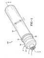
diffuser 21 by the rapid escape of the gasses that are stored at pressures of up to about 630 kg/cm2. As the hot particle fragments leave thediffuser 21 exiting through a plurality ofvent openings 22 that are oriented radially with respect to a longitudinal axis of thehousing 10. The hot particle fragments impinge directly onto the fabric of the airbag (not shown) surrounding the diffuser. In some cases small holes burnt in the fabric of the airbag create a local weakness that initiates small tears causing some of the inflation gasses to be lost to the ambient atmosphere. This problem is not desirable and should be avoided, but the benefits of the reliability achieved by using these pyrotechnic type igniters means that a solution is needed to slow or prevent these microscopic "meteor like" burning fragments and shards from damaging the airbag fabric. The present invention according to the characterizing portion ofclaim 1 and the dependent claims provides a simple cost effective solution to this problem that works in combination with a cold gas inflator or a hybrid inflator or a pyrotechnic inflator wherein the inflation gasses discharge from the inflator in radial directions with respect to a longitudinal axis of the inflator housing. - FIG. 1 is a perspective view of a cold gas inflator of the present invention.
- FIG. 2 is an exploded view of the cold gas inflator of FIG. 1.
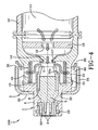
- FIG. 3 is a cross sectional plan view of the cold gas inflator of FIG. 1.
- FIG. 4 is an enlarged cross sectional view of the diffuser portion of the cold gas inflator of FIG. 1.
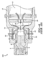
- FIG. 5 is an enlarged cross sectional view of an alternative inflator according to the present invention.
- FIG. 6 is an enlarged cross sectional plan view of a prior art cold gas inflator with a radial flow diffuser similar to
US 6 629 703 . - FIGs. 1 through 4 show an
exemplary airbag inflator 100 of the present invention for use in an automotive safety restraint system. The exemplary device is a cold gas airbag inflator; however, the present invention applies to other types of airbag inflators such as hybrid inflators having both stored gas and a pyrotechnic charge or a pyrotechnic type inflator without stored gas. The inventive concept works well with any of these inflators that discharge inflation gasses in a direction oriented radially with respect to a longitudinal axis of the inflator. The following description while emphasizing the preferred embodiment cold gas inflator is not limited to that type of airbag inflator exclusively, but rather is intended to include these other types of airbag inflators as well. Thecold gas inflator 100 has ahousing 10 that acts as a pressure vessel containing storedgas 11, which is released from the inflator during a vehicle crash to inflate an airbag (not shown). Thehousing 10 has a generally cylindrical or tubular shape. It is understood that an inflator housing having a spherical or disk like shape may also be used in the practice of the present invention. Thehousing 10 has a circular cross section. Thehousing 10 may be made of stainless steel, low carbon steel, or any other suitable material that has sufficient strength and extremely low permeability to the gas. - The ideal characteristics for the
stored gas 11 are that the gas is inert, is not highly temperature sensitive, and has a high inflation speed. According to the present invention, the storage pressure of the inert gas is about 630 kg/cm2 at 23 °C. It is possible to design a cold gas inflator that operates properly under a pressure lower or higher using either an inert or diatomic gas. The stored gas can include one or more gases, which include argon, neon, xenon, helium and nitrogen. Preferably, the gas is pure helium or a mixture of argon and helium. The preferred percentages for an argon/helium system include a gas mixture having from 5-100% helium with the remainder being argon. - In FIG. 3 the
housing 10 receives storedgas 11 through agas fill port 13 in afirst end 6 of the housing. The gas fill port is sealed by aplug 12 made from carbon steel to prevent gas from escaping after thehousing 10 has been filled to the desired pressure. It is preferred that the plug is secured to thegas fill port 13 by a resistance weld, but one skilled in the art realizes that other types of welding could be utilized to fuse theplug 12 to thehousing 10. - The
gas fill port 13 is located at thefirst end 6 of thehousing 10, and anopening device 1 for unblocking the discharge opening 14 by rupturing a sealing member, such as aburst disk 17 is located on the other end of the housing. In FIG. 3 the opening device is attached to a generallycylindrical diffuser 21, which is attached to thehousing 10 by a circumferential weld, specifically a friction weld, where a butt joint is formed as shown. The diffuser may be made of stainless steel, low carbon steel, or any other material having sufficient strength. - When the
burst disk 17 is attached to thediffuser 21, it can have a flat shape, but the burst disk flexes towards theopening device 1 when the storedgas 11 applies pressure against the burst disk resulting in the burst disk having a dome shaped configuration. It is recognized by those skilled in the art that a rigid diffuser may also be used in conjunction with a hydro-forming process which bulges the disc in the direction of the opening device to amount greater than seen during gas fill. In doing so the gas fill rate may be increased without risk of pre-mature failure of the burst disk. - The
burst disk 17 seals thedischarge opening 14 and prevents the storedgas 11 from escaping from thehousing 10. The burst disk may be made from stainless steel, nickel-chromium alloys such as INCONEL, nickel-copper alloys such as MONEL or any other suitable material. The hardness of the burst disk should be between "half hard" and "full hard" to minimize burst disk thickness. Hardness is the degree to which a metal will resist cutting, abrasion, penetration, bending and stretching and the indicated hardness will differ with the specific apparatus and technique of measuring. The preferred thickness of the burst disk is in the range of 0.203 mm to 0.254 mm. The burst disk is attached to the diffuser by a YAG Laser but could be attached by other welding techniques. - The
opening device 1 comprises an electrically actuatedigniter 3, anend cap 4, and optionally anigniter nozzle 8. Theopening device 1 is positioned so that the longitudinal axis of the opening device is essentially coincident with a longitudinal axis of thehousing 10. Theigniter 3 communicates with a central processing unit (not shown), which in turn communicates with a crash sensor means (not shown). Theelectric firing pins 2 are insulated from one another and connected by a bridge wire. (not shown) The bridge wire is preferably embedded in one or more layers of pyrotechnic compositions designed to generate a shockwave to rupture theburst disk 17. An example of a suitable pyrotechnic composition or pyrotechnic substance is zirconium potassium perchlorate or ZPP; however, one skilled in the art realizes that other pyrotechnic substance could be used in the present invention. Examples of igniter suppliers include SDI and EMS-Patvag. The preferred embodiment has a bridge wire igniter, but a semiconductor bridge igniter or a smart igniter can also be used. - An
end cap 4 houses theigniter 3. The igniter can be connected to theend cap 4 by crimping at 20a as shown in FIG. 4 or by welding, screwing, or other suitable attachment means. Theend cap 4 is attached to thediffuser 21 by welding, but one skilled in the art knows other methods of attachment. - The
opening device 1 may have anigniter nozzle 8 for directing the output energy from the ignition of the pyrotechnic substance towards theburst disk 17. In FIG. 1, the nozzle is tapered inward in the direction of theburst disk 17. Without theigniter nozzle 8, the igniter would still rupture theburst disk 17 but will need to be loaded with a larger quantity of the pyrotechnic substance. It is also possible to utilize an igniter with reinforced walls, which would eliminate the need for anozzle 8. These reinforcement walls would act in a similar fashion to thenozzle 8 by focusing the output energy in the direction of theburst disc 17. - In FIG. 4 the
nozzle 8 is attached to theend cap 4 by crimping, but other methods of attachment are suitable such as press fit or welding. The nozzle is preferably made from standard carbon steel and has anopening 9 in the range of 2 mm to 8 mm in diameter that is smaller than thedischarge opening 14. Astabilizer block 50 secures the igniter in place and is in turn secured to theenc cap 4 by alock ring 23. - Upon the detection of a crash or a sudden deceleration, the pyrotechnic substance in the igniter is ignited by a bridgewire, and the explosion of the pyrotechnic substance generates a shockwave that impacts the
burst disk 17 destroys the sealing integrity of the burst disk as a sealing member. In order for theburst disk 17 to rupture, theopening device 1 is disposed less than 8.0 mm away from a center of the fully domed burst disk. After theburst disk 17 is opened, stored gas from thehousing 10 escapes through thevent openings 22 in directions that are oriented radially with respect to the longitudinal axis of thehousing 10. The cold gas inflator has ascreen 15 to capture fragments from the ruptured burst disk so that these fragments will not enter the airbag. - There are several methods of controlling the gas flow rate. One method of controlling the gas flow rate is to increase or decrease the diameter of the
vent openings 22. Another method is to increase or decrease the diameter of thedischarge opening 14. Lastly, a regulatingorifice plate 18 can be installed in the pressure vessel to control the rate of gas discharge. In FIG. 4 theorifice plate 19 is mounted spaced slightly apart from theburst disk 17. The storedgas 11 flows through thethrottle orifice 19 of theorifice plate 18. The presence of theorifice plate 18 affects the flow rate of the storedgas 11 through thedischarge opening 14 since thedischarge opening 14 has a greater area than thethrottle orifice 19. A first quantity of storedgas 11, which is the storedgas 11 between thedischarge opening 14 and theorifice plate 18, flows through thedischarge opening 14. On the other hand, a second quantity of storedgas 11, which is stored between theorifice plate 18 and thefirst end 6 of the inflator, must flow through both thethrottle orifice 19 and thedischarge opening 14. It is preferred that theorifice plate 18 be disposed in a position closer to the second end 7 of the pressure vessel than thefirst end 6 to limit the amount of unthrottled gas to an energy level sufficient to complete the rupturing of the burst disc. - In FIG. 6 the prior art diffuser of
inflator 200 has the gasses escape under pressure through thevent openings 22 that are oriented radially with respect to the longitudinal axis of thehousing 10. The vent openings are oriented around the diffuser in a uniform circumferential spacing to create a thrust neutral exhausting of the gasses as they fill the airbag. In the present invention thecold gas inflator 100 the thrust neutral exhausting of gasses is maintained even as the gasses impinge a cup shapedouter shield 5. The cup shapedouter shield 5 is securely welded to theend cap 4. - Upon assembly a
hole 32 in theclosed end plate 30 of the cup shapedouter shield 5 receives theend cap 4. Theend plate 30 abuts against theend cap 4 and is welded to theend cap 4. Acylindrical portion 34 of theouter shield 5 extends from theend plate 30 completely encircling thevent opening 22 and extending axially beyond thevent openings 22 toward the inflator housing. Thecylindrical portion 34 of the cup shaped end cap has a larger inside diameter than the diameter of the external surface at the diffuser near thevent opening 22 and therefore creates angas flow passage 80 that extends axially with respect to the longitudinal axis of thehousing 10. Thecylindrical portion 34 of the cup shaped end cap extends longitudinally back toward thefirst end 6 of theinflator housing 10. Theend 36 of the cylindrical portion of the cup shaped end cap stops short of the enlarged portion of the diffuser creating a 360 degree circumferentially extendingradial gap 82 between theend 36 of the cylindrical portion of the cup shaped end cap and the diffuser. Preferably thegap 82 and theaxial passage 80 have an opening area larger than the total area of the combinedvent openings 22 of the diffuser. In this way the flow of gas is not restricted, but is redirected. The cup shapedouter shield 5 not only redirects the gas flow, but actually causes the gas flow to reverse direction prior to exhausting out of thegap 82 in a thrust neutral flow pattern. The force of the escaping gasses impinging theclosed end plate 30 of the cup shaped outer shield cancels out some of the relatively small longitudinal thrust forces created as the gas escapes through thethrottle orifice 19. - More importantly as gas under pressure exhausts out of an orifice the flow chills rapidly as a phenomenon commonly known as the Thompson Joule effect occurs causing a rapid drop in temperature. This phenomenon actually can create frost or icing of the surfaces on the diffuser and outer shield. Accordingly at the instant of gas discharge the cup shaped
outer shield 5 will force any small hot particles that get past thescreen 15 inside the diffuser to impact the inner surfaces of theouter shield 5 which will absorb a large portion of the heat energy as well as redirect the kinetic energy longitudinally along the housing. As these tiny particles have a greater mass than theexhaust gasses 11 they tend to move along the housing and further cool prior to exiting at thegap 82. In practice it has been found that the use of the cup shapedouter shield 5 virtually eliminates the phenomena of burnt holes and tears in the airbag. - The
outer shield 5 is preferably made of steel and has a sufficient thickness and mass to absorb the forces of the gasses while cooling and redirecting the minute particles that passed through the screen without adversely diminishing the airbag fill rate. Additional filtration would have altered the flow rate and thus the time to fill the airbag that is not desirable or as controllable. - The cup shaped
outer shield 5 has an outside diameter substantially equal to or slightly less than the diameter of thehousing 10 of the inflator to facilitate mounting and attachment. - In FIG. 5 an alternative embodiment of an
airbag inflator 100A is shown wherein theigniter 3 is mounted on the side of thediffuser 21 and theouter shield 5 is welded to the axial end of the diffuser so that the samegas flow pathways member 17 is destroyed when theigniter 3 is activated. Theigniter 3 is contained in aconnector closure 99 that is connected to theelectric firing pins 2 and anend cap 4. Upon actuation theigniter 3 produces a blast that moves ahammer 24 striking a knock outrod 26 that is held in place by the hold downpin 25 causing the sealingmember 27 to move allowing thegas 11 to pass through theopening 19 and then through thevent openings 22 near the axial end of theinflator 100A striking theouter shield 5. Thevent openings 22 are oriented in radial directions with respect to a longitudinal axis of thehousing 10. Theouter shield 5 is beneficially used in any inflator type device having a radial discharge of the inflation gasses wherein hot shards or burning particulate can be first deflected by or impacted into the inner surfaces of the shield to absorb both the heat and the kinetic energy in an effort to protect the airbag cushion from burn holes.
Claims (12)
- An airbag inflator (100, 100A) comprising: a housing (10) for storing a gas (11) or a pyrotechnic charge, or for storing both a gas (11) and a pyrotechnic charge; a diffuser (21) attached to an end of the housing (10), the diffuser (21) having a plurality of vent openings (22) therethrough, the vent openings oriented radially with respect to a longitudinal axis of the housing (10); characterized by a cup shaped outer shield (5) attached to the inflator external of the diffuser (21) and encircling the plurality of radially oriented vent openings (22) and an open face of the cup extending toward the housing (10).
- An airbag inflator (100, 100A) according to claim 1 further comprising a sealing member (17) for sealing a discharge opening (19); and a device (3) for destroying the sealing integrity of the sealing member (17)
- An airbag inflator (100, 100A) according to claim 1 or 2 wherein the outer shield (5) has a closed end attached to an end of the inflator and a cylindrical portion extending from the end plate.
- An airbag inflator (100, 100A) according to claim 3 wherein the cylindrical portion of the outer shield (5) encircles a portion of the diffuser (21) and has an inside surface spaced from the encircled portion of the diffuser (21) to form an axially extending passage.
- An airbag inflator (100, 100A) according to any of claims 1 - 4 wherein the outer shield (5) redirects the gas flow from a direction oriented radially with respect to a longitudinal axis of the housing (10) to axially with respect to a longitudinal axis of the housing (10) within the cylindrical portion prior to exiting the open end of the outer shield (5).
- An airbag inflator (100, 100A) according to any of claims 1 - 5 wherein the open end of the outer shield (5) is axially spaced from an enlarged diameter portion of the diffuser (21) to form a gap passage 360 degrees circumferentially around the inflator.
- An airbag inflator (100, 100A) according to any of claims 1 - 6 wherein the outer shield (5) has an outside diameter equal to or less than the diameter of the housing (10).
- An airbag inflator (100, 100A) according to any of claims 1 - 7, wherein the inflator is a cold gas type inflator.
- An airbag inflator (100, 100A) according to any of claims 1 - 7, wherein the inflator is a hybrid type inflator having both a stored gas and a pyrotechnic charge for generation of the inflation gas.
- An airbag inflator (100, 100A) according to any of claims 1 - 7, wherein the inflator is a pyrotechnic charged type inflator without stored gas (11), the pyrotechnic charge generates the inflation gasses for filling an airbag.
- An airbag inflator (100, 100A) according to any of claims 1 - 10, wherein the housing (10) has a tubular shape.
- An airbag inflator (100, 100A) according to any of claims 1 - 10, wherein the housing (10) has a disk shape.
Priority Applications (1)
| Application Number | Priority Date | Filing Date | Title |
|---|---|---|---|
| EP06021175A EP1911636A1 (en) | 2006-10-09 | 2006-10-09 | Airbag inflator with redirected flow diffuser shield |
Applications Claiming Priority (1)
| Application Number | Priority Date | Filing Date | Title |
|---|---|---|---|
| EP06021175A EP1911636A1 (en) | 2006-10-09 | 2006-10-09 | Airbag inflator with redirected flow diffuser shield |
Publications (1)
| Publication Number | Publication Date |
|---|---|
| EP1911636A1 true EP1911636A1 (en) | 2008-04-16 |
Family
ID=37772567
Family Applications (1)
| Application Number | Title | Priority Date | Filing Date |
|---|---|---|---|
| EP06021175A Withdrawn EP1911636A1 (en) | 2006-10-09 | 2006-10-09 | Airbag inflator with redirected flow diffuser shield |
Country Status (1)
| Country | Link |
|---|---|
| EP (1) | EP1911636A1 (en) |
Cited By (1)
| Publication number | Priority date | Publication date | Assignee | Title |
|---|---|---|---|---|
| US10202096B2 (en) | 2016-12-13 | 2019-02-12 | Autoliv Asp, Inc. | Thrust vector tuning of inflator devices |
Citations (5)
| Publication number | Priority date | Publication date | Assignee | Title |
|---|---|---|---|---|
| US5468012A (en) * | 1994-06-13 | 1995-11-21 | Trw Vehicle Safety Systems Inc. | Air bag module |
| JPH0911842A (en) * | 1995-06-30 | 1997-01-14 | Nippon Plast Co Ltd | Air bag device |
| WO1997027087A1 (en) * | 1996-01-26 | 1997-07-31 | General Motors Corporation | Air bag assembly with diffuser |
| US5704637A (en) * | 1995-05-19 | 1998-01-06 | Kabushiki Kaisha Tokai-Rika-Denki-Seisakusho | Air bag apparatus |
| WO2002057121A1 (en) * | 2001-01-22 | 2002-07-25 | Toyo Tire & Rubber Co., Ltd. | Airbag device |
-
2006
- 2006-10-09 EP EP06021175A patent/EP1911636A1/en not_active Withdrawn
Patent Citations (5)
| Publication number | Priority date | Publication date | Assignee | Title |
|---|---|---|---|---|
| US5468012A (en) * | 1994-06-13 | 1995-11-21 | Trw Vehicle Safety Systems Inc. | Air bag module |
| US5704637A (en) * | 1995-05-19 | 1998-01-06 | Kabushiki Kaisha Tokai-Rika-Denki-Seisakusho | Air bag apparatus |
| JPH0911842A (en) * | 1995-06-30 | 1997-01-14 | Nippon Plast Co Ltd | Air bag device |
| WO1997027087A1 (en) * | 1996-01-26 | 1997-07-31 | General Motors Corporation | Air bag assembly with diffuser |
| WO2002057121A1 (en) * | 2001-01-22 | 2002-07-25 | Toyo Tire & Rubber Co., Ltd. | Airbag device |
Cited By (5)
| Publication number | Priority date | Publication date | Assignee | Title |
|---|---|---|---|---|
| US10202096B2 (en) | 2016-12-13 | 2019-02-12 | Autoliv Asp, Inc. | Thrust vector tuning of inflator devices |
| CN110035931A (en) * | 2016-12-13 | 2019-07-19 | 奥托立夫Asp公司 | The thrust vectoring of inflator device tunes |
| WO2018111833A3 (en) * | 2016-12-13 | 2019-11-21 | Autoliv Asp, Inc. | Thrust vector tuning of inflator devices |
| EP3585657A4 (en) * | 2016-12-13 | 2020-11-11 | Autoliv ASP, Inc. | Thrust vector tuning of inflator devices |
| CN110035931B (en) * | 2016-12-13 | 2021-07-27 | 奥托立夫Asp公司 | Thrust vector tuning for inflator devices |
Similar Documents
| Publication | Publication Date | Title |
|---|---|---|
| US6629703B2 (en) | Opening device for a cold gas inflator | |
| KR970011515B1 (en) | Hybrid inflator | |
| US6857657B2 (en) | Inflator having a support member capable of sliding to open the pressure vessel | |
| KR100848588B1 (en) | Compact multi-level inflator | |
| KR101077922B1 (en) | Gas generator and multi-levle gas generator for airbag or other safety device | |
| US6746046B2 (en) | Dual flow inflator for a vehicular airbag system | |
| KR20050049510A (en) | Dual stage inflator with extended gas delivery for a vehicular airbag system | |
| EP0734919A1 (en) | Pressurized gas inflator for vehicle occupant protection systems | |
| JPH05201304A (en) | Expander assembly | |
| KR20070042092A (en) | Dual stage hybrid airbag inflator | |
| US5782486A (en) | Rapid gas-fill apparatus and method | |
| US6273462B1 (en) | Air bag inflator | |
| JP2555541B2 (en) | Hybrid inflator | |
| US6007097A (en) | Flammable gas initiated pyrotechnic inflator | |
| JP5707328B2 (en) | Inflator for airbag and airbag inflation method | |
| JP4115087B2 (en) | Two-stage gas generator | |
| JP2005520734A (en) | Dual-flow inflator for vehicle airbag systems | |
| US6709011B2 (en) | Leak detection enhancing insert for an airbag inflator assembly | |
| JPH07195997A (en) | Device for inflating inflatable restraint means for vehicle passenger | |
| EP1453706B1 (en) | Opening device for a cold gas inflator | |
| EP1911636A1 (en) | Airbag inflator with redirected flow diffuser shield | |
| US6981718B2 (en) | Projectile firing barrel | |
| US7393008B2 (en) | Pressure wave gas generator | |
| US20040212182A1 (en) | Inflator with movable pressure vessel | |
| WO2004106124A1 (en) | Inflator |
Legal Events
| Date | Code | Title | Description |
|---|---|---|---|
| PUAI | Public reference made under article 153(3) epc to a published international application that has entered the european phase |
Free format text: ORIGINAL CODE: 0009012 |
|
| AK | Designated contracting states |
Kind code of ref document: A1 Designated state(s): AT BE BG CH CY CZ DE DK EE ES FI FR GB GR HU IE IS IT LI LT LU LV MC NL PL PT RO SE SI SK TR |
|
| AX | Request for extension of the european patent |
Extension state: AL BA HR MK RS |
|
| AKX | Designation fees paid | ||
| REG | Reference to a national code |
Ref country code: DE Ref legal event code: 8566 |
|
| STAA | Information on the status of an ep patent application or granted ep patent |
Free format text: STATUS: THE APPLICATION IS DEEMED TO BE WITHDRAWN |
|
| 18D | Application deemed to be withdrawn |
Effective date: 20081017 |