EP1911608A1 - Tire with sidewall insert - Google Patents
Tire with sidewall insert Download PDFInfo
- Publication number
- EP1911608A1 EP1911608A1 EP20070118097 EP07118097A EP1911608A1 EP 1911608 A1 EP1911608 A1 EP 1911608A1 EP 20070118097 EP20070118097 EP 20070118097 EP 07118097 A EP07118097 A EP 07118097A EP 1911608 A1 EP1911608 A1 EP 1911608A1
- Authority
- EP
- European Patent Office
- Prior art keywords
- annular
- segment
- apex
- tire
- sidewall
- Prior art date
- Legal status (The legal status is an assumption and is not a legal conclusion. Google has not performed a legal analysis and makes no representation as to the accuracy of the status listed.)
- Granted
Links
Images


Classifications
-
- B—PERFORMING OPERATIONS; TRANSPORTING
- B60—VEHICLES IN GENERAL
- B60C—VEHICLE TYRES; TYRE INFLATION; TYRE CHANGING; CONNECTING VALVES TO INFLATABLE ELASTIC BODIES IN GENERAL; DEVICES OR ARRANGEMENTS RELATED TO TYRES
- B60C17/00—Tyres characterised by means enabling restricted operation in damaged or deflated condition; Accessories therefor
- B60C17/0009—Tyres characterised by means enabling restricted operation in damaged or deflated condition; Accessories therefor comprising sidewall rubber inserts, e.g. crescent shaped inserts
-
- B—PERFORMING OPERATIONS; TRANSPORTING
- B60—VEHICLES IN GENERAL
- B60C—VEHICLE TYRES; TYRE INFLATION; TYRE CHANGING; CONNECTING VALVES TO INFLATABLE ELASTIC BODIES IN GENERAL; DEVICES OR ARRANGEMENTS RELATED TO TYRES
- B60C15/00—Tyre beads, e.g. ply turn-up or overlap
- B60C15/06—Flipper strips, fillers, or chafing strips and reinforcing layers for the construction of the bead
- B60C15/0603—Flipper strips, fillers, or chafing strips and reinforcing layers for the construction of the bead characterised by features of the bead filler or apex
- B60C15/0607—Flipper strips, fillers, or chafing strips and reinforcing layers for the construction of the bead characterised by features of the bead filler or apex comprising several parts, e.g. made of different rubbers
-
- B—PERFORMING OPERATIONS; TRANSPORTING
- B60—VEHICLES IN GENERAL
- B60C—VEHICLE TYRES; TYRE INFLATION; TYRE CHANGING; CONNECTING VALVES TO INFLATABLE ELASTIC BODIES IN GENERAL; DEVICES OR ARRANGEMENTS RELATED TO TYRES
- B60C17/00—Tyres characterised by means enabling restricted operation in damaged or deflated condition; Accessories therefor
- B60C17/0009—Tyres characterised by means enabling restricted operation in damaged or deflated condition; Accessories therefor comprising sidewall rubber inserts, e.g. crescent shaped inserts
- B60C17/0027—Tyres characterised by means enabling restricted operation in damaged or deflated condition; Accessories therefor comprising sidewall rubber inserts, e.g. crescent shaped inserts comprising portions of different rubbers in a single insert
-
- B—PERFORMING OPERATIONS; TRANSPORTING
- B60—VEHICLES IN GENERAL
- B60C—VEHICLE TYRES; TYRE INFLATION; TYRE CHANGING; CONNECTING VALVES TO INFLATABLE ELASTIC BODIES IN GENERAL; DEVICES OR ARRANGEMENTS RELATED TO TYRES
- B60C1/00—Tyres characterised by the chemical composition or the physical arrangement or mixture of the composition
- B60C2001/0033—Compositions of the sidewall inserts, e.g. for runflat
-
- Y—GENERAL TAGGING OF NEW TECHNOLOGICAL DEVELOPMENTS; GENERAL TAGGING OF CROSS-SECTIONAL TECHNOLOGIES SPANNING OVER SEVERAL SECTIONS OF THE IPC; TECHNICAL SUBJECTS COVERED BY FORMER USPC CROSS-REFERENCE ART COLLECTIONS [XRACs] AND DIGESTS
- Y10—TECHNICAL SUBJECTS COVERED BY FORMER USPC
- Y10T—TECHNICAL SUBJECTS COVERED BY FORMER US CLASSIFICATION
- Y10T152/00—Resilient tires and wheels
- Y10T152/10—Tires, resilient
- Y10T152/10495—Pneumatic tire or inner tube
- Y10T152/10819—Characterized by the structure of the bead portion of the tire
-
- Y—GENERAL TAGGING OF NEW TECHNOLOGICAL DEVELOPMENTS; GENERAL TAGGING OF CROSS-SECTIONAL TECHNOLOGIES SPANNING OVER SEVERAL SECTIONS OF THE IPC; TECHNICAL SUBJECTS COVERED BY FORMER USPC CROSS-REFERENCE ART COLLECTIONS [XRACs] AND DIGESTS
- Y10—TECHNICAL SUBJECTS COVERED BY FORMER USPC
- Y10T—TECHNICAL SUBJECTS COVERED BY FORMER US CLASSIFICATION
- Y10T152/00—Resilient tires and wheels
- Y10T152/10—Tires, resilient
- Y10T152/10495—Pneumatic tire or inner tube
- Y10T152/10855—Characterized by the carcass, carcass material, or physical arrangement of the carcass materials
- Y10T152/10864—Sidewall stiffening or reinforcing means other than main carcass plies or foldups thereof about beads
Definitions
- Tire constructions generally include a sidewall insert variously for support of the tire sidewall.
- a sidewall insert variously for support of the tire sidewall.
- an apex may be included to provide support in the sidewall near the bead.
- runflat tires i.e. tires that are capable of being used while uninflated (with total loss of air pressure other than ambient atmospheric pressure)
- one or more runflat inserts may be included in the sidewall to provide support in the event of a tire deflation.
- the present invention is directed to a pneumatic tire according to claim 1.
- Dependent claims refer to preferred embodiments of the invention.
- FIGS. 1-6 a partial cross-sectional view of pneumatic tire 1 is shown with a circumferential tread 2, bead portion 3 and sidewall portion 4 extending radially outward from said bead portion 3 to said tread 2.
- the sidewall portion 4 contains an internal two-segment sidewall rubber insert in a form of an apex 6.
- the apex 6 is of a tapered shape extending from the bead portion 3 radially outward with its apex terminating in the sidewall 4.
- the apex 6 may be seen to have a relative thick section at its base proximate to the bead 3 and taper to a relatively narrow section at its opposite end distal to the bead.
- the apex 6 is composed of, or configured as, two overlapping rubber segments, namely:
- the sidewall portion 4 contains the two-segment apex 6 of FIG 1 together with an additional, spaced apart, sidewall insert 7 spaced apart from and extending radially outward from the apex 6 in an overlapping relationship with the apex 6 in which the spaced apart overlapping portion of the spaced apart sidewall insert 7 is axially inward of the apex 6.
- the sidewall portion 4 contains a sidewall apex 6 similar in shape to the two-segment apex 6 of FIG 1 except that the apex is of a unitary rubber composition, together with a an additional spaced-apart sidewall insert 7 of the shape and positioning as the additional spaced-apart sidewall insert 7 of FIG 2 except that the spaced-apart sidewall insert for FIG 3 is composed of a two-segment insert, namely a radially inner segment 7A and a radially outer segment 7B.
- the spaced apart sidewall insert 7 is composed of, or configured as, two overlapping rubber segments, namely:
- the sidewall portion 4 contains the two-segment sidewall apex 6 of the shape, positioning and composition of the apex 6 of FIG 2 and the spaced apart two segmented sidewall rubber insert 7 of the shape, positioning and composition of the spaced apart sidewall rubber insert 7 of FIG 3.
- the sidewall portion 4 contains a sidewall apex 6 similar in shape to the two-segment apex 6 of FIG 1 except that the apex is of a unitary rubber composition, together with a an additional spaced-apart sidewall insert 7 of the shape and positioning as the additional spaced-apart sidewall insert 7 of FIG 3 except that the spaced-apart sidewall insert for FIG 3 is composed of a three-segment insert, namely a radially inner segment 7A and a radially outer segment 7B and a third segment 7C disposed between segments 7A and 7C.
- the spaced apart sidewall insert 7 is composed of, or configured as, three overlapping rubber segments, namely:
- the sidewall portion 4 contains a sidewall apex 6 similar in shape to the two-segment apex 6 of FIG 1 except that the apex is of a unitary rubber composition, together with a an additional spaced-apart sidewall insert 7 of the shape and positioning as the additional spaced-apart sidewall insert 7 of FIG 2 except that the spaced-apart sidewall insert for FIG 6 is composed of a two-segment insert, namely an axially inner segment 7A and a axially outer segment 7B.
- the spaced apart sidewall insert 7 is composed of, or configured as, two overlapping rubber segments, namely:
- FIG 6 shows two segments in the insert 7
- a third segment (not shown) may be disposed axially outward of segment 7B.
- a cord reinforced rubber ply (not shown) is envisioned for the Figures which is contained in the sidewall 4 and extends from the bead portion 3 through the crown portion of the tire (not identified in the drawing) radially inward of the tire tread portion 2 to the opposite bead portion (not shown) of the tire.
- the ply is positioned between said apex 6 and said spaced apart sidewall rubber insert 7 in which the spaced apart sidewall rubber insert is thereby positioned adjacent to and axially inward from the ply.
- the apex 6 is envisioned as being positioned adjacent to and axially outward from the ply.
- the ply is envisioned as extending to the axially inward side of the bead 3 and apex 6, then around the radially inward part of the bead portion 3 to thereafter, in what is typically referred to as a ply turn-up portion, extending to the axially outward side of the bead portion 3 and apex 6 for a relatively short distance radially outward into the tire sidewall 4.
- a ply turn-up portion is well known to those having skill in such art in which the apex 6 is therefore adjacent to and axially outward of the ply and adjacent to and axially inward of the ply turn-up.
- a pneumatic tire comprising a circumferential tread, two spaced apart beads, and sidewalls connecting said beads and tread, wherein said sidewalls contains at least one internal annular sidewall insert comprising at least two annular segments; wherein a portion of each of said at least two annular segments segments are in a overlapping configuration with each other with a diagonal interface therebetween to form at least one overlapping zone; wherein each of the at least two annular segments comprises a rubber composition comprising at least one diene based rubber and at least one vulcanization modifier selected from the group consisting of ⁇ , ⁇ -bis(N,N'-dihydrocarbylthiocarbamamamoyldithio)alkanes, bismaleimides, and biscitraconimides; and wherein the concentration of vulcanization modifier in the first annular segment is less than the concentration of vulcanization modifier in the second annular segment.
- the sidewall insert is an apex extending from a bead radially outward into the tire sidewall, wherein the first annular segment is disposed radially proximate to the bead and the second annular segment is disposed radially distal to the bead.
- the sidewall insert is a runflat insert spaced radially apart from an apex.
- At least one vulcanization modifier may be added to the rubber composition in one or more of the annular segments of the sidewall insert.
- vulcanization modifier it is meant that such a vulcanization modifier will have the effect of affecting the vulcanization of the rubber composition during the normal cure cycle of the tire, such that the cure state of the overall sidewall insert is more uniform.
- the insert segment disposed in the region of greatest sidewall thickness will have the least amount of modifier, since the modifiers generally have the effect of slowing cure.
- the at least two annular segments are in disposed in sidewall regions having cross-sectional thicknesses; wherein a first of said annular segments is disposed in a sidewall region having a cross-sectional thickness that is greater than the greatest cross-sectional thickness of the sidewall region wherein a second of said annular segments is disposed.
- a cured rubber composition for the purposes of the discussion for this invention, is a sulfur cured rubber composition, conventionally a sulfur cured diene-based rubber, which has been cured to a substantial inflection of its modulus (y axis) versus time (x axis) curve.
- a property related to modulus such as torque
- such curve conventionally is a curve with a positive slope which rises over time until it experiences a substantial inflection in a manner that its slope reaches a plateau where it becomes substantially horizontal. In such region of a slope transition, which is somewhat of a maximization of the slope, although the slope might still very gradually rise, it is considered that the rubber composition is fully cured.
- the shape of the curve may be somewhat modified, depending on the modifier used.
- the net effect of the vulcanization modifier is to modify the vulcanization of the rubber composition in each segment of the insert such that the overall cure of the insert is more uniform.
- the vulcanization modifier for use in the second rubber composition include ⁇ , ⁇ -bis(N,N'-dihydrocarbylthiocarbamamoyldithio)alkanes, bismaleimides, and biscitracon im ides.
- the vulcanization modifier is a ⁇ , ⁇ -bis(N,N'-dihydrocarbylthiocarbamamoyldithio)alkanes.
- Suitable ⁇ , ⁇ -bis(N,N'-dihydrocarbylthiocarbamamoyldithio)alkanes include 1,2-bis(N,N'-dibenzylthiocarbamoyl-dithio)ethane; 1,3-bis(N,N'-dibenzylthiocarbamoyldithio)propane; 1,4-bis(N,N'-dibenzylthiocarbamoyldithio)butane; 1,5-bis(N,N'-dibenzylthiocarbamoyl-dithio)pentane; 1,6-bis(N,N'-dibenzylthiocarbamoyldithio)hexane; 1,7
- the vulcanization modifier is a bismaleimide.
- Suitable bismaleimides include N, N'-m-phenylene bismaleimide, available as HVA-2 from DuPont.
- the vulcanization modifier is a citraconimide.
- Suitable citraconimidies include N, N'-m-xylylene biscitraconimide, also known as 1,3-bis(citraconimidomethyl)benzene, available as Perkalink® 900 from Flexsys.
- the rubber composition in one or more annular segments comprises from 1 to 15 parts by weight, per 100 parts by weight of elastomer (phr), of the vulcanization modifier. In another embodiment, the rubber composition comprises from 2 to 8 phr of vulcanization modifier.
- the amount of vulcanization modifier ranges from 0 to 15 parts by weight, per 100 parts by weight of elastomer.
- the vulcanization modifier is 1,3-bis(citraconimidomethyl)benzene.
- the concentration of vulcanization modifier in two or more of the at least two segments will be different.
- the weight ratio of vulcanization modifier in the first segment to vulcanization modifier in the second segment is less than 0.9; in another embodiment less than 0.8; in another embodiment less than 0.7.
- the weight ration of 1,3-bis(citraconimidomethyl)benzene in the first segment to 1,3-bis(citraconimidomethyl)benzene in the second segment is less than 0.9; in another embodiment less than 0.8; in another embodiment less than 0.7.
- the amount of vulcanization modifier in the first segment ranges from 0 to 5 phr and the amount of vulcanization modifier in the second segment ranges from 1 to 15 phr.
- the amount of 1,3-bis(citraconimidomethyl)benzene in the first segment ranges from 0 to 5 phr and the amount of 1,3-bis(citraconimidomethyl)benzene in the second segment ranges from 1 to 15 phr.
- the at least two annular segments further comprises a third annular segment, wherein the third annular segment is disposed radially proximate to the apex, the second annular segment is disposed radially distal from the apex, and the first annular segment is disposed radially between the first and second annular segments.
- the weight ratio of vulcanization modifier in the first segment to vulcanization modifier in the second segment is less than 0.9; in another embodiment, 0.8; in another embodiment, 0.7, and wherein the weight ratio of vulcanization modifier in the first segment to vulcanization modifier in the third segment is less than 0.9; in another embodiment 0.8; in another embodiment 0.7.
- the weight ratio of 1,3-bis(citraconimidomethyl)benzene in the first segment to 1,3-bis(citraconimidomethyl)benzene in the second segment is less than 0.9; in another embodiment, 0.8; in another embodiment, 0.7, and wherein the weight ratio of 1,3-bis(citraconimidomethyl)benzene in the first segment to 1,3-bis(citraconimidomethyl)benzene in the third segment is less than 0.9; in another embodiment 0.8; in another embodiment 0.7.
- the amount of vulcanization modifier in the first segment ranges from 0 to 5 phr and the amount of vulcanization modifier in the second and third segments ranges from 1 to 15 phr.
- the amount of 1,3-bis(citraconimidomethyl)benzene in the first segment ranges from 0 to 5 phr and the amount of 1,3-bis(citraconimidomethyl)benzene in the second and third segments ranges from 1 to 15 phr.
- the present invention may be used with rubbers or elastomers containing olefinic unsaturation.
- rubber or elastomer containing olefinic unsaturation is intended to include both natural rubber and its various raw and reclaim forms as well as various synthetic rubbers.
- the terms “rubber” and “ elastomer” may be used interchangeably, unless otherwise prescribed.
- the terms “rubber composition”, “compounded rubber” and “rubber compound” are used interchangeably to refer to rubber which has been blended or mixed with various ingredients and materials.
- Representative synthetic polymers are the homopolymerization products of butadiene and its homologues and derivatives, for example, methylbutadiene, dimethylbutadiene and pentadiene as well as copolymers such as those formed from butadiene or its homologues or derivatives with other unsaturated monomers.
- acetylenes for example, vinyl acetylene
- olefins for example, isobutylene, which copolymerizes with isoprene to form butyl rubber
- vinyl compounds for example, acrylic acid, acrylonitrile (which polymerize with butadiene to form NBR), methacrylic acid and styrene, the latter compound polymerizing with butadiene to form SBR, as well as vinyl esters and various unsaturated aldehydes, ketones and ethers, e.g., acrolein, methyl isopropenyl ketone and vinylethyl ether.
- synthetic rubbers include neoprene (polychloroprene), polybutadiene (including cis-1,4-polybutadiene), polyisoprene (including cis-1,4-polyisoprene), butyl rubber, halobutyl rubber such as chlorobutyl rubber or bromobutyl rubber, styrene/isoprene/butadiene rubber, copolymers of 1,3-butadiene or isoprene with monomers such as styrene, acrylonitrile and methyl methacrylate, as well as ethylene/propylene terpolymers, also known as ethylene/propylene/diene monomer (EPDM), and in particular, ethylene/propylene/ dicyclopentadiene terpolymers.
- neoprene polychloroprene
- polybutadiene including cis-1,4-polybutadiene
- rubbers which may be used include alkoxysilyl end functionalized solution polymerized polymers (SBR, PBR, IBR and SIBR), silicon-coupled and tin-coupled star-branched polymers.
- SBR alkoxysilyl end functionalized solution polymerized polymers
- PBR polybutadiene
- IBR IBR
- SIBR silicon-coupled star-branched polymers.
- the preferred rubber or elastomers are polybutadiene and SBR.
- the rubber is preferably of at least two of diene based rubbers.
- a combination of two or more rubbers is preferred such as cis 1,4-polyisoprene rubber (natural or synthetic, although natural is preferred), 3,4-polyisoprene rubber, styrene/isoprene/butadiene rubber, emulsion and solution polymerization derived styrene/butadiene rubbers, cis 1,4-polybutadiene rubbers and emulsion polymerization prepared butadiene/acrylonitrile copolymers.
- an emulsion polymerization derived styrene/butadiene might be used having a relatively conventional styrene content of 20 to 28 percent bound styrene or, for some applications, an E-SBR having a medium to relatively high bound styrene content, namely, a bound styrene content of 30 to 45 percent.
- E-SBR emulsion polymerization prepared E-SBR
- styrene and 1,3-butadiene are copolymerized as an aqueous emulsion.
- the bound styrene content can vary, for example, from 5 to 50 percent.
- the E-SBR may also contain acrylonitrile to form a terpolymer rubber, as E-SBAR, in amounts, for example, of 2 to 30 weight percent bound acrylonitrile in the terpolymer.
- Emulsion polymerization prepared styrene/butadiene/acrylonitrile copolymer rubbers containing 2 to 40 weight percent bound acrylonitrile in the copolymer are also contemplated as diene based rubbers for use in this invention.
- S-SBR solution polymerization prepared SBR
- S-SBR typically has a bound styrene content in a range of 5 to 50, preferably 9 to 36, percent.
- the S-SBR can be conveniently prepared, for example, by organo lithium catalyzation in the presence of an organic hydrocarbon solvent.
- cis 1,4-polybutadiene rubber may be used.
- BR cis 1,4-polybutadiene rubber
- Such BR can be prepared, for example, by organic solution polymerization of 1,3-butadiene.
- the BR may be conveniently characterized, for example, by having at least a 90 percent cis 1,4-content.
- cis 1,4-polyisoprene and cis 1,4-polyisoprene natural rubber are well known to those having skill in the rubber art.
- the rubber composition may also include up to 70 phr of processing oil.
- Processing oil may be included in the rubber composition as extending oil typically used to extend elastomers. Processing oil may also be included in the rubber composition by addition of the oil directly during rubber compounding.
- the processing oil used may include both extending oil present in the elastomers, and process oil added during compounding.
- Suitable process oils include various oils as are known in the art, including aromatic, paraffinic, napthenic, vegetable oils, and low PCA oils, such as MES, TDAE, SRAE and heavy naphthenic oils.
- the vulcanizable rubber composition may include from 10 to 150 phr of silica.
- siliceous pigments which may be used in the rubber compound include conventional pyrogenic and precipitated siliceous pigments (silica). In one embodiment, precipitated silica is used.
- Such conventional silicas might be characterized, for example, by having a BET surface area, as measured using nitrogen gas.
- the BET surface area may be in the range of 40 to 600 square meters per gram. The BET method of measuring surface area is described in the Journal of the American Chemical Society, Volume 60, Page 304 (1930 ).
- the conventional silica may also be characterized by having a dibutylphthalate (DBP) absorption value in a range of 100 to 400, alternatively 150 to 300.
- DBP dibutylphthalate
- silicas such as, only for example herein, silicas commercially available from PPG Industries under the Hi-Sil trademark with designations 210, 243, etc; silicas available from Rhodia, with, for example, designations of Z1165MP and Z165GR and silicas available from Degussa AG with, for example, designations VN2 and VN3, etc.
- the vulcanizable rubber composition may include from 1 to 100 phr of carbon black, crosslinked particulate polymer gel, ultra high molecular weight polyethylene (UHMWPE) or plasticized starch.
- UHMWPE ultra high molecular weight polyethylene
- carbon blacks can be used as a conventional filler.
- Representative examples of such carbon blacks include N110, N121, N134, N220, N231, N234, N242, N293, N299, N315, N326, N330, N332, N339, N343, N347, N351, N358, N375, N539, N550, N582, N630, N642, N650, N683, N754, N762, N765, N774, N787, N907, N908, N990 and N991.
- These carbon blacks have iodine absorptions ranging from 9 to 145 g/kg and DBP number ranging from 34 to 150 cm 3 /100 g.
- fillers may be used in the rubber composition including, but not limited to, particulate fillers including ultra high molecular weight polyethylene (UHMWPE), particulate polymer gels including but not limited to those disclosed in US-B- 6,242,534 ; US-B- 6,207,757 ; US-B- 6,133,364 ; US-B- 6,372,857 ; US-B-5,395,891 ; or US-B- 6,127,488 , and plasticized starch composite filler including that disclosed in US-B- 5,672,639 .
- UHMWPE ultra high molecular weight polyethylene
- the rubber composition for use in the tire tread may contain a conventional sulfur containing organosilicon compound.
- suitable sulfur containing organosilicon compounds are of the formula: Z - Alk - S n - Alk - Z II in which Z is selected from the group consisting of where R 6 is an alkyl group of 1 to 4 carbon atoms, cyclohexyl or phenyl; R 7 is alkoxy of 1 to 8 carbon atoms, or cycloalkoxy of 5 to 8 carbon atoms; Alk is a divalent hydrocarbon of 1 to 18 carbons atoms and n is an integer of 2 to 8.
- the sulfur containing organosilicon compounds are the 3,3'-bis(trimethoxy or triethoxy silylpropyl) sulfides. In one embodiment, the sulfur containing organosilicon compounds are 3,3'-bis(triethoxysilylpropyl) disulfide and 3,3'-bis(triethoxysilylpropyl) tetrasulfide.
- suitable sulfur containing organosilicon compounds include compounds disclosed in US-B 6,608,125 .
- suitable sulfur containing organosilicon compounds include those disclosed in US-A- 2003/0130535 .
- the sulfur containing organosilicon compound is Si-363 from Degussa.
- the amount of the sulfur containing organosilicon compound in a rubber composition will vary depending on the level of other additives that are used. Generally speaking, the amount of the compound will range from 0.5 to 20 phr. In one embodiment, the amount will range from 1 to 10 phr.
- the rubber composition would be compounded by methods generally known in the rubber compounding art, such as mixing the various sulfur-vulcanizable constituent rubbers with various commonly used additive materials such as, for example, sulfur donors, curing aids such as activators, and processing additives, such as oils, resins including tackifying resins and plasticizers, fillers, pigments, fatty acid, zinc oxide, waxes, antioxidants and antiozonants and peptizing agents.
- additives mentioned above are selected and commonly used in conventional amounts.
- sulfur donors include elemental sulfur (free sulfur), an amine disulfide, polymeric polysulfide and sulfur olefin adducts.
- the sulfur-vulcanizing agent is elemental sulfur.
- the sulfur-vulcanizing agent may be used in an amount ranging from 0.5 to 8 phr.
- Typical amounts of tackifier resins, if used, comprise 0.5 to 10 phr.
- Typical amounts of processing aids comprise 1 to 50 phr.
- Typical amounts of antioxidants comprise 1 to 5 phr.
- Representative antioxidants may be, for example, diphenyl-p-phenylenediamine.
- Typical amounts of antiozonants comprise 1 to 5 phr.
- Typical amounts of fatty acids, if used, which can include stearic acid comprise 0.5 to 3 phr.
- Typical amounts of zinc oxide comprise 2 to 5 phr.
- Typical amounts of waxes comprise 1 to 5 phr.
- Typical amounts of peptizers comprise 0.1 to 1 phr.
- Typical peptizers may be, for example, pentachlorothiophenol and dibenzamidodiphenyl disulfide.
- Accelerators are used to control the time and/or temperature required for vulcanization and to improve the properties of the vulcanizate.
- a single accelerator system may be used, i.e., primary accelerator.
- the primary accelerator(s) may be used in total amounts ranging from 0.5 to 4.
- the primary accelerator is a sulfenamide.
- the secondary accelerator may be a guanidine, dithiocarbamate or thiuram compound.
- the mixing of the rubber composition can be accomplished by methods known to those having skill in the rubber mixing art.
- the ingredients are typically mixed in at least two stages, namely, at least one non-productive stage followed by a productive mix stage.
- the final curatives including sulfur-vulcanizing agents are typically mixed in the final stage which is conventionally called the "productive" mix stage in which the mixing typically occurs at a temperature, or ultimate temperature, lower than the mix temperature(s) than the preceding non-productive mix stage(s).
- the rubber composition may be subjected to a thermomechanical mixing step.
- the thermomechanical mixing step generally comprises a mechanical working in a mixer or extruder for a period of time suitable in order to produce a rubber temperature between 140°C and 190°C.
- the appropriate duration of the thermomechanical working varies as a function of the operating conditions, and the volume and nature of the components.
- the thermomechanical working may be from 1 to 20 minutes.
- each of the annular segments of the sidewall insert may comprises the rubber composition.
- the annular segments may be produced using methods as are known in the art, including but not limited to extrusion, calendaring, and the like.
- the first and second (and additional) annular segments may be co-extruded, or singly extruded or calendared and then used to build the tire in the usual manner.
- the pneumatic tire of the present invention may be a race tire, passenger tire, aircraft tire, agricultural, earthmover, off-the-road, truck tire, and the like.
- the tire is a passenger or truck tire.
- the tire may be a radial or bias.
- Vulcanization of the pneumatic tire of the present invention is generally carried out at conventional temperatures ranging from 100°C to 200°C. Any of the usual vulcanization processes may be used such as heating in a press or mold, heating with superheated steam or hot air.
Abstract
said annular segments are disposed with an interface (8,9) therebetween;
each of the at least two annular segments includes a rubber composition comprising at least one diene based rubber and at least one vulcanization modifier selected from the group consisting of α,ω-bis(N,N'-dihydrocarbylthiocarbamamoyldithio)alkanes, bismaleimides, and biscitraconimides; and
the concentration of vulcanization modifier in the first annular segment is less than the concentration of vulcanization modifier in the second annular segment.
Description
- Tire constructions generally include a sidewall insert variously for support of the tire sidewall. In the case of conventional tires, an apex may be included to provide support in the sidewall near the bead. In the case of runflat tires, i.e. tires that are capable of being used while uninflated (with total loss of air pressure other than ambient atmospheric pressure), one or more runflat inserts may be included in the sidewall to provide support in the event of a tire deflation.
- These sidewall inserts, both apexes and runflat inserts, are typically of nonuniform cross-section with a relatively thick section and one or more relatively thin sections. Cure of the inserts is problematic owing to the uneven heat transfer in the thick and thin sections. It would then be advantageous to have a more evenly cured sidewall insert.
- The present invention is directed to a pneumatic tire according to
claim 1. Dependent claims refer to preferred embodiments of the invention. -
- Figure 1 is a fragmentary cross-sectional view of a tire having an apex as sidewall insert according to the invention.
- Figure 2 is a fragmentary cross-sectional view of a tire having an apex as sidewall insert according to the invention and a further conventional runflat tire sidewall insert.
- Figure 3 is a fragmentary cross-sectional view of a tire having a runflat tire sidewall insert according to the invention and a conventional apex.
- Figure 4 is a fragmentary cross-section view of a tire having an apex as sidewall insert and a runflat tire sidewall insert according to the invention.
- Figure 5 is a fragmentary cross-sectional view of a tire showing a runflat tire sidewall insert according to the invention having three annular segments and a conventional apex.
- Figure 6 is a fragmentary cross-sectional view of a tire showing a runflat tire sidewall insert according to the invention having two axially adjacent annular segments and a conventional apex.
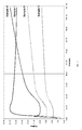
- Figure 7 is a trace of torque versus time for several rubber compositions according to the invention.
- In the drawings FIGS. 1-6, a partial cross-sectional view of
pneumatic tire 1 is shown with acircumferential tread 2,bead portion 3 andsidewall portion 4 extending radially outward from saidbead portion 3 to saidtread 2. - In FIG 1, the
sidewall portion 4 contains an internal two-segment sidewall rubber insert in a form of anapex 6. Theapex 6 is of a tapered shape extending from thebead portion 3 radially outward with its apex terminating in thesidewall 4. - The
apex 6 may be seen to have a relative thick section at its base proximate to thebead 3 and taper to a relatively narrow section at its opposite end distal to the bead. - The
apex 6 is composed of, or configured as, two overlapping rubber segments, namely: - (A) a
first segment 6A as a radially inner component of theapex 6 extending radially outward from thebead portion 3, and - (B) a
second segment 6B as a radially outer component of theapex 6 extending radially outward from saidinner segment 6A further into saidsidewall portion 4; - In FIG 2, the
sidewall portion 4 contains the two-segment apex 6 of FIG 1 together with an additional, spaced apart, sidewall insert 7 spaced apart from and extending radially outward from theapex 6 in an overlapping relationship with theapex 6 in which the spaced apart overlapping portion of the spacedapart sidewall insert 7 is axially inward of theapex 6. - In FIG 3, the
sidewall portion 4 contains asidewall apex 6 similar in shape to the two-segment apex 6 of FIG 1 except that the apex is of a unitary rubber composition, together with a an additional spaced-apart sidewall insert 7 of the shape and positioning as the additional spaced-apart sidewall insert 7 of FIG 2 except that the spaced-apart sidewall insert for FIG 3 is composed of a two-segment insert, namely a radiallyinner segment 7A and a radiallyouter segment 7B. - In particular, the spaced
apart sidewall insert 7 is composed of, or configured as, two overlapping rubber segments, namely: - (A) a
first segment 7A as a radially inner component of the insert, and - (B) a
second segment 7B as a radially outer component of thesidewall insert 7 extending radially outward from saidinner segment 7A further into saidsidewall portion 4 and approaching atread portion 2 of thetire 1; - In FIG 4, the
sidewall portion 4 contains the two-segment sidewall apex 6 of the shape, positioning and composition of theapex 6 of FIG 2 and the spaced apart two segmentedsidewall rubber insert 7 of the shape, positioning and composition of the spaced apartsidewall rubber insert 7 of FIG 3. - In FIG 5, the the
sidewall portion 4 contains asidewall apex 6 similar in shape to the two-segment apex 6 of FIG 1 except that the apex is of a unitary rubber composition, together with a an additional spaced-apart sidewall insert 7 of the shape and positioning as the additional spaced-apart sidewall insert 7 of FIG 3 except that the spaced-apart sidewall insert for FIG 3 is composed of a three-segment insert, namely a radiallyinner segment 7A and a radiallyouter segment 7B and a third segment 7C disposed betweensegments 7A and 7C. - In particular, in FIG 5 the spaced apart
sidewall insert 7 is composed of, or configured as, three overlapping rubber segments, namely: - (A) a
first segment 7A as a radially inner component of the insert, - (B) a
second segment 7B as a radially outer component of the sidewall insert 7, and - (C) a third segment 7C disposed between
first segment 7A andsecond segment 7B, with segment 7C extending radially outward from saidinner segment 7A, andsecond segment 7B extending radially outward from said inner segment 7C further into saidsidewall portion 4 and approaching atread portion 2 of thetire 1; - In FIG 6, the
sidewall portion 4 contains asidewall apex 6 similar in shape to the two-segment apex 6 of FIG 1 except that the apex is of a unitary rubber composition, together with a an additional spaced-apart sidewall insert 7 of the shape and positioning as the additional spaced-apart sidewall insert 7 of FIG 2 except that the spaced-apart sidewall insert for FIG 6 is composed of a two-segment insert, namely an axiallyinner segment 7A and a axiallyouter segment 7B. - In particular, in FIG 6 the spaced apart
sidewall insert 7 is composed of, or configured as, two overlapping rubber segments, namely: - (A) a
first segment 7A as an axially inner component of the insert, and - (B) a
second segment 7B as an axially outer component of thesidewall insert 7 disposed axially outward from saidinner segment 7A in saidsidewall portion 4; - While the embodiment shown in FIG 6 shows two segments in the
insert 7, other embodiments are contemplated wherein more than two segments may be used, for example, a third segment (not shown) may be disposed axially outward ofsegment 7B. - For consideration of these drawings, a cord reinforced rubber ply (not shown) is envisioned for the Figures which is contained in the
sidewall 4 and extends from thebead portion 3 through the crown portion of the tire (not identified in the drawing) radially inward of thetire tread portion 2 to the opposite bead portion (not shown) of the tire. For Figures 2, 3, 4, 5, and 6 it is envisioned that the ply is positioned between saidapex 6 and said spaced apartsidewall rubber insert 7 in which the spaced apart sidewall rubber insert is thereby positioned adjacent to and axially inward from the ply. For all of the Figures, theapex 6 is envisioned as being positioned adjacent to and axially outward from the ply. The ply is envisioned as extending to the axially inward side of thebead 3 andapex 6, then around the radially inward part of thebead portion 3 to thereafter, in what is typically referred to as a ply turn-up portion, extending to the axially outward side of thebead portion 3 andapex 6 for a relatively short distance radially outward into thetire sidewall 4. Such ply with its ply turn-up portion is well known to those having skill in such art in which theapex 6 is therefore adjacent to and axially outward of the ply and adjacent to and axially inward of the ply turn-up. - Consistent with the embodiments shown in the drawings, there is disclosed a pneumatic tire comprising a circumferential tread, two spaced apart beads, and sidewalls connecting said beads and tread, wherein said sidewalls contains at least one internal annular sidewall insert comprising at least two annular segments;
wherein a portion of each of said at least two annular segments segments are in a overlapping configuration with each other with a diagonal interface therebetween to form at least one overlapping zone;
wherein each of the at least two annular segments comprises a rubber composition comprising at least one diene based rubber and at least one vulcanization modifier selected from the group consisting of α,ω-bis(N,N'-dihydrocarbylthiocarbamamoyldithio)alkanes, bismaleimides, and biscitraconimides; and
wherein the concentration of vulcanization modifier in the first annular segment is less than the concentration of vulcanization modifier in the second annular segment. - In one embodiment, the sidewall insert is an apex extending from a bead radially outward into the tire sidewall, wherein the first annular segment is disposed radially proximate to the bead and the second annular segment is disposed radially distal to the bead.
- In one embodiment, the sidewall insert is a runflat insert spaced radially apart from an apex.
- In one embodiment, to obtain a more uniform cure in the sidewall insert, at least one vulcanization modifier may be added to the rubber composition in one or more of the annular segments of the sidewall insert. By "vulcanization modifier", it is meant that such a vulcanization modifier will have the effect of affecting the vulcanization of the rubber composition during the normal cure cycle of the tire, such that the cure state of the overall sidewall insert is more uniform. Generally, the insert segment disposed in the region of greatest sidewall thickness will have the least amount of modifier, since the modifiers generally have the effect of slowing cure. Thus, in one embodiment, the at least two annular segments are in disposed in sidewall regions having cross-sectional thicknesses; wherein a first of said annular segments is disposed in a sidewall region having a cross-sectional thickness that is greater than the greatest cross-sectional thickness of the sidewall region wherein a second of said annular segments is disposed.
- A cured rubber composition, for the purposes of the discussion for this invention, is a sulfur cured rubber composition, conventionally a sulfur cured diene-based rubber, which has been cured to a substantial inflection of its modulus (y axis) versus time (x axis) curve. Depending on the method used to measure the cure kinetics, a property related to modulus, such as torque, may be used. In particular, such curve conventionally is a curve with a positive slope which rises over time until it experiences a substantial inflection in a manner that its slope reaches a plateau where it becomes substantially horizontal. In such region of a slope transition, which is somewhat of a maximization of the slope, although the slope might still very gradually rise, it is considered that the rubber composition is fully cured. In the presence of a vulcanization modifier, the shape of the curve may be somewhat modified, depending on the modifier used. The net effect of the vulcanization modifier is to modify the vulcanization of the rubber composition in each segment of the insert such that the overall cure of the insert is more uniform.
- In one embodiment, the vulcanization modifier for use in the second rubber composition include α,ω-bis(N,N'-dihydrocarbylthiocarbamamoyldithio)alkanes, bismaleimides, and biscitracon im ides.
- In one embodiment, the vulcanization modifier is a α,ω-bis(N,N'-dihydrocarbylthiocarbamamoyldithio)alkanes. Suitable α,ω-bis(N,N'-dihydrocarbylthiocarbamamoyldithio)alkanes include 1,2-bis(N,N'-dibenzylthiocarbamoyl-dithio)ethane; 1,3-bis(N,N'-dibenzylthiocarbamoyldithio)propane; 1,4-bis(N,N'-dibenzylthiocarbamoyldithio)butane; 1,5-bis(N,N'-dibenzylthiocarbamoyl-dithio)pentane; 1,6-bis(N,N'-dibenzylthiocarbamoyldithio)hexane; 1,7-bis(N,N'-dibenzylthiocarbamoyldithio)heptane; 1,8-bis(N,N'-dibenzylthiocarbamoyl-dithio)octane; 1,9-bis(N,N'-dibenzylthiocarbamoyldithio)nonane; and 1,10-bis(N,N'-dibenzylthiocarbamoyldithio)decane. In one embodiment, the vulcanization modifier is 1,6-bis(N,N'-dibenzylthiocarbamoyldithio)hexane available as Vulcuren® from Bayer.
- In one embodiment, the vulcanization modifier is a bismaleimide. Suitable bismaleimides include N, N'-m-phenylene bismaleimide, available as HVA-2 from DuPont.
- In one embodiment, the vulcanization modifier is a citraconimide. Suitable citraconimidies include N, N'-m-xylylene biscitraconimide, also known as 1,3-bis(citraconimidomethyl)benzene, available as Perkalink® 900 from Flexsys.
- In one embodiment, the rubber composition in one or more annular segments comprises from 1 to 15 parts by weight, per 100 parts by weight of elastomer (phr), of the vulcanization modifier. In another embodiment, the rubber composition comprises from 2 to 8 phr of vulcanization modifier.
- In one embodiment, the amount of vulcanization modifier ranges from 0 to 15 parts by weight, per 100 parts by weight of elastomer.
- In one embodiment, the vulcanization modifier is 1,3-bis(citraconimidomethyl)benzene.
- In order to obtain a more uniform cure in the sidewall insert, the concentration of vulcanization modifier in two or more of the at least two segments will be different. In one embodiment, the weight ratio of vulcanization modifier in the first segment to vulcanization modifier in the second segment is less than 0.9; in another embodiment less than 0.8; in another embodiment less than 0.7. In one embodiment, the weight ration of 1,3-bis(citraconimidomethyl)benzene in the first segment to 1,3-bis(citraconimidomethyl)benzene in the second segment is less than 0.9; in another embodiment less than 0.8; in another embodiment less than 0.7.
- In one embodiment, the amount of vulcanization modifier in the first segment ranges from 0 to 5 phr and the amount of vulcanization modifier in the second segment ranges from 1 to 15 phr.
- In one embodiment the amount of 1,3-bis(citraconimidomethyl)benzene in the first segment ranges from 0 to 5 phr and the amount of 1,3-bis(citraconimidomethyl)benzene in the second segment ranges from 1 to 15 phr.
- In one embodiment, the at least two annular segments further comprises a third annular segment, wherein the third annular segment is disposed radially proximate to the apex, the second annular segment is disposed radially distal from the apex, and the first annular segment is disposed radially between the first and second annular segments.
- In one embodiment, the weight ratio of vulcanization modifier in the first segment to vulcanization modifier in the second segment is less than 0.9; in another embodiment, 0.8; in another embodiment, 0.7, and wherein the weight ratio of vulcanization modifier in the first segment to vulcanization modifier in the third segment is less than 0.9; in another embodiment 0.8; in another embodiment 0.7.
- In one embodiment, the weight ratio of 1,3-bis(citraconimidomethyl)benzene in the first segment to 1,3-bis(citraconimidomethyl)benzene in the second segment is less than 0.9; in another embodiment, 0.8; in another embodiment, 0.7, and wherein the weight ratio of 1,3-bis(citraconimidomethyl)benzene in the first segment to 1,3-bis(citraconimidomethyl)benzene in the third segment is less than 0.9; in another embodiment 0.8; in another embodiment 0.7.
- In one embodiment, the amount of vulcanization modifier in the first segment ranges from 0 to 5 phr and the amount of vulcanization modifier in the second and third segments ranges from 1 to 15 phr.
- In one embodiment, the amount of 1,3-bis(citraconimidomethyl)benzene in the first segment ranges from 0 to 5 phr and the amount of 1,3-bis(citraconimidomethyl)benzene in the second and third segments ranges from 1 to 15 phr.
- The present invention may be used with rubbers or elastomers containing olefinic unsaturation. The phrase "rubber or elastomer containing olefinic unsaturation" is intended to include both natural rubber and its various raw and reclaim forms as well as various synthetic rubbers. In the description of this invention, the terms "rubber" and " elastomer" may be used interchangeably, unless otherwise prescribed. The terms "rubber composition", "compounded rubber" and "rubber compound" are used interchangeably to refer to rubber which has been blended or mixed with various ingredients and materials. Representative synthetic polymers are the homopolymerization products of butadiene and its homologues and derivatives, for example, methylbutadiene, dimethylbutadiene and pentadiene as well as copolymers such as those formed from butadiene or its homologues or derivatives with other unsaturated monomers. Among the latter are acetylenes, for example, vinyl acetylene; olefins, for example, isobutylene, which copolymerizes with isoprene to form butyl rubber; vinyl compounds, for example, acrylic acid, acrylonitrile (which polymerize with butadiene to form NBR), methacrylic acid and styrene, the latter compound polymerizing with butadiene to form SBR, as well as vinyl esters and various unsaturated aldehydes, ketones and ethers, e.g., acrolein, methyl isopropenyl ketone and vinylethyl ether. Specific examples of synthetic rubbers include neoprene (polychloroprene), polybutadiene (including cis-1,4-polybutadiene), polyisoprene (including cis-1,4-polyisoprene), butyl rubber, halobutyl rubber such as chlorobutyl rubber or bromobutyl rubber, styrene/isoprene/butadiene rubber, copolymers of 1,3-butadiene or isoprene with monomers such as styrene, acrylonitrile and methyl methacrylate, as well as ethylene/propylene terpolymers, also known as ethylene/propylene/diene monomer (EPDM), and in particular, ethylene/propylene/ dicyclopentadiene terpolymers. Additional examples of rubbers which may be used include alkoxysilyl end functionalized solution polymerized polymers (SBR, PBR, IBR and SIBR), silicon-coupled and tin-coupled star-branched polymers. The preferred rubber or elastomers are polybutadiene and SBR.
- In one aspect the rubber is preferably of at least two of diene based rubbers. For example, a combination of two or more rubbers is preferred such as cis 1,4-polyisoprene rubber (natural or synthetic, although natural is preferred), 3,4-polyisoprene rubber, styrene/isoprene/butadiene rubber, emulsion and solution polymerization derived styrene/butadiene rubbers, cis 1,4-polybutadiene rubbers and emulsion polymerization prepared butadiene/acrylonitrile copolymers.
- In one aspect of this invention, an emulsion polymerization derived styrene/butadiene (E-SBR) might be used having a relatively conventional styrene content of 20 to 28 percent bound styrene or, for some applications, an E-SBR having a medium to relatively high bound styrene content, namely, a bound styrene content of 30 to 45 percent.
- By emulsion polymerization prepared E-SBR, it is meant that styrene and 1,3-butadiene are copolymerized as an aqueous emulsion. The bound styrene content can vary, for example, from 5 to 50 percent. In one aspect, the E-SBR may also contain acrylonitrile to form a terpolymer rubber, as E-SBAR, in amounts, for example, of 2 to 30 weight percent bound acrylonitrile in the terpolymer.
- Emulsion polymerization prepared styrene/butadiene/acrylonitrile copolymer rubbers containing 2 to 40 weight percent bound acrylonitrile in the copolymer are also contemplated as diene based rubbers for use in this invention.
- The solution polymerization prepared SBR (S-SBR) typically has a bound styrene content in a range of 5 to 50, preferably 9 to 36, percent. The S-SBR can be conveniently prepared, for example, by organo lithium catalyzation in the presence of an organic hydrocarbon solvent.
- In one embodiment, cis 1,4-polybutadiene rubber (BR) may be used. Such BR can be prepared, for example, by organic solution polymerization of 1,3-butadiene. The BR may be conveniently characterized, for example, by having at least a 90 percent cis 1,4-content.
- The cis 1,4-polyisoprene and cis 1,4-polyisoprene natural rubber are well known to those having skill in the rubber art.
- The term "phr" as used herein, and according to conventional practice, refers to "parts by weight of a respective material per 100 parts by weight of rubber, or elastomer."
- The rubber composition may also include up to 70 phr of processing oil. Processing oil may be included in the rubber composition as extending oil typically used to extend elastomers. Processing oil may also be included in the rubber composition by addition of the oil directly during rubber compounding. The processing oil used may include both extending oil present in the elastomers, and process oil added during compounding. Suitable process oils include various oils as are known in the art, including aromatic, paraffinic, napthenic, vegetable oils, and low PCA oils, such as MES, TDAE, SRAE and heavy naphthenic oils.
- The vulcanizable rubber composition may include from 10 to 150 phr of silica.
- The commonly employed siliceous pigments which may be used in the rubber compound include conventional pyrogenic and precipitated siliceous pigments (silica). In one embodiment, precipitated silica is used.
- Such conventional silicas might be characterized, for example, by having a BET surface area, as measured using nitrogen gas. In one embodiment, the BET surface area may be in the range of 40 to 600 square meters per gram. The BET method of measuring surface area is described in the Journal of the American Chemical Society, Volume 60, Page 304 (1930).
- The conventional silica may also be characterized by having a dibutylphthalate (DBP) absorption value in a range of 100 to 400, alternatively 150 to 300.
- Various commercially available silicas may be used, such as, only for example herein, silicas commercially available from PPG Industries under the Hi-Sil trademark with designations 210, 243, etc; silicas available from Rhodia, with, for example, designations of Z1165MP and Z165GR and silicas available from Degussa AG with, for example, designations VN2 and VN3, etc.
- The vulcanizable rubber composition may include from 1 to 100 phr of carbon black, crosslinked particulate polymer gel, ultra high molecular weight polyethylene (UHMWPE) or plasticized starch.
- Commonly employed carbon blacks can be used as a conventional filler. Representative examples of such carbon blacks include N110, N121, N134, N220, N231, N234, N242, N293, N299, N315, N326, N330, N332, N339, N343, N347, N351, N358, N375, N539, N550, N582, N630, N642, N650, N683, N754, N762, N765, N774, N787, N907, N908, N990 and N991. These carbon blacks have iodine absorptions ranging from 9 to 145 g/kg and DBP number ranging from 34 to 150 cm3/100 g.
- Other fillers may be used in the rubber composition including, but not limited to, particulate fillers including ultra high molecular weight polyethylene (UHMWPE), particulate polymer gels including but not limited to those disclosed in
US-B- 6,242,534 ;US-B- 6,207,757 ;US-B- 6,133,364 ;US-B- 6,372,857 ;US-B-5,395,891 ; orUS-B- 6,127,488 , and plasticized starch composite filler including that disclosed inUS-B- 5,672,639 . - In one embodiment the rubber composition for use in the tire tread may contain a conventional sulfur containing organosilicon compound. Examples of suitable sulfur containing organosilicon compounds are of the formula:
Z - Alk - Sn - Alk - Z II
in which Z is selected from the group consisting of
- In one embodiment, the sulfur containing organosilicon compounds are the 3,3'-bis(trimethoxy or triethoxy silylpropyl) sulfides. In one embodiment, the sulfur containing organosilicon compounds are 3,3'-bis(triethoxysilylpropyl) disulfide and 3,3'-bis(triethoxysilylpropyl) tetrasulfide.
- In another embodiment, suitable sulfur containing organosilicon compounds include compounds disclosed in
US-B 6,608,125 . These sulfur containing organosilicon compounds are of the formula G-C(==O) -S-CH2CH2CH2SiX3 wherein each X is an independently selected RO- group wherein each R is independently selected from the group consisting of hydrogen, alkyl that may or may not contain unsaturation, alkenyl groups, aryl groups, and aralkyl groups, such moieties other than hydrogen having from 1 to 18 carbon atoms, and G is a monovalent alkyl of from 6 to 8 carbon atoms. In one embodiment, the sulfur containing organosilicon compounds includes 3-(octanoylthio)-1-propyltriethoxysilane, CH3(CH2)6C(=O) -S-CH2CH2CH2Si(OCH2CH3)3, which is available commercially as NXT™ from GE Silicones. - In another embodiment suitable sulfur containing organosilicon compounds include those disclosed in
US-A- 2003/0130535 . - In one embodiment, the sulfur containing organosilicon compound is Si-363 from Degussa.
- The amount of the sulfur containing organosilicon compound in a rubber composition will vary depending on the level of other additives that are used. Generally speaking, the amount of the compound will range from 0.5 to 20 phr. In one embodiment, the amount will range from 1 to 10 phr.
- It is readily understood by those having skill in the art that the rubber composition would be compounded by methods generally known in the rubber compounding art, such as mixing the various sulfur-vulcanizable constituent rubbers with various commonly used additive materials such as, for example, sulfur donors, curing aids such as activators, and processing additives, such as oils, resins including tackifying resins and plasticizers, fillers, pigments, fatty acid, zinc oxide, waxes, antioxidants and antiozonants and peptizing agents. As known to those skilled in the art, depending on the intended use of the sulfur vulcanizable and sulfur-vulcanized material (rubbers), the additives mentioned above are selected and commonly used in conventional amounts. Representative examples of sulfur donors include elemental sulfur (free sulfur), an amine disulfide, polymeric polysulfide and sulfur olefin adducts. In one embodiment, the sulfur-vulcanizing agent is elemental sulfur. The sulfur-vulcanizing agent may be used in an amount ranging from 0.5 to 8 phr. Typical amounts of tackifier resins, if used, comprise 0.5 to 10 phr. Typical amounts of processing aids comprise 1 to 50 phr. Typical amounts of antioxidants comprise 1 to 5 phr. Representative antioxidants may be, for example, diphenyl-p-phenylenediamine. Typical amounts of antiozonants comprise 1 to 5 phr. Typical amounts of fatty acids, if used, which can include stearic acid comprise 0.5 to 3 phr. Typical amounts of zinc oxide comprise 2 to 5 phr. Typical amounts of waxes comprise 1 to 5 phr. Typical amounts of peptizers comprise 0.1 to 1 phr. Typical peptizers may be, for example, pentachlorothiophenol and dibenzamidodiphenyl disulfide.
- Accelerators are used to control the time and/or temperature required for vulcanization and to improve the properties of the vulcanizate. In one embodiment, a single accelerator system may be used, i.e., primary accelerator. The primary accelerator(s) may be used in total amounts ranging from 0.5 to 4. In one embodiment, the primary accelerator is a sulfenamide. If a second accelerator is used, the secondary accelerator may be a guanidine, dithiocarbamate or thiuram compound.
- The mixing of the rubber composition can be accomplished by methods known to those having skill in the rubber mixing art. For example, the ingredients are typically mixed in at least two stages, namely, at least one non-productive stage followed by a productive mix stage. The final curatives including sulfur-vulcanizing agents are typically mixed in the final stage which is conventionally called the "productive" mix stage in which the mixing typically occurs at a temperature, or ultimate temperature, lower than the mix temperature(s) than the preceding non-productive mix stage(s). The rubber composition may be subjected to a thermomechanical mixing step. The thermomechanical mixing step generally comprises a mechanical working in a mixer or extruder for a period of time suitable in order to produce a rubber temperature between 140°C and 190°C. The appropriate duration of the thermomechanical working varies as a function of the operating conditions, and the volume and nature of the components. For example, the thermomechanical working may be from 1 to 20 minutes.
- The rubber composition may be incorporated in a sidewall insert of a runflat tire. Thus, each of the annular segments of the sidewall insert may comprises the rubber composition. The annular segments may be produced using methods as are known in the art, including but not limited to extrusion, calendaring, and the like. The first and second (and additional) annular segments may be co-extruded, or singly extruded or calendared and then used to build the tire in the usual manner.
- The pneumatic tire of the present invention may be a race tire, passenger tire, aircraft tire, agricultural, earthmover, off-the-road, truck tire, and the like. In one embodiment, the tire is a passenger or truck tire. The tire may be a radial or bias.
- Vulcanization of the pneumatic tire of the present invention is generally carried out at conventional temperatures ranging from 100°C to 200°C. Any of the usual vulcanization processes may be used such as heating in a press or mold, heating with superheated steam or hot air.
- The invention is further illustrated by the following examples.
- In this example, the effect of adding a vulcanization modifier to a rubber composition is illustrated. Five samples were prepared following the recipes in Table 1, with amounts given in phr. Each composition was prepared in a multistage mix procedure with at least one non-productive stage and one productive stage. The samples were then tested for cure kinetics with results as shown in Figure 7.
Table 1 Sample 1 2 3 4 5 Natural Rubber 80 100 100 100 100 Polybutadiene1 20 0 0 0 0 Carbon Black 30 32 32 50 10 Silica 15 0 0 0 0 Coupling Agent 25 0 0 0 0 Antidegradants3 3.25 3 3 3 3 Zinc Oxide 5 2.5 2.5 2.5 2.5 Stearic Acid 1 1 1 1 1 Sulfur 3 2 2 2 2 Accelerators4 4.75 2 2 2 2 Vulcanization Modifier5 0 4 8 10 8 Vulcanization Modifier6 0 0 0 0.1 0 1 Budene 1207 from The Goodyear Tire & Rubber Company
2 bis (alkoxysilylalkyl)polysulfide type, 50% on carbon black
3 p-phenylene diamines and quinolines
4 sulfenamides
5 1,3-bis(citraconimidomethyl)benzene
6 N-cyclohexylthiophthalimide
Claims (10)
- A pneumatic tire comprising a circumferential tread (2), two spaced apart beads (3), and a sidewall (4) connecting said bead (3) and said tread (2),
wherein said sidewall contains at least one internal annular sidewall insert (6, 7), said internal annular sidewall insert (6, 7) comprising a first annular segment (6A, 7A) and a second adjacent annular segment (6B, 7B), wherein said first and second annular segments are disposed with an interface (8, 9) therebetween,
wherein each of said first and second annular segments comprises a rubber composition comprising at least one diene based rubber and at least one vulcanization modifier selected from the group consisting of α,ω-bis(N,N'-dihydrocarbylthiocarbamamoyldithio)alkanes, bismaleimides, and biscitraconimides, and wherein the concentration of vulcanization modifier in the first annular segment (6A, 7A) is less than the concentration of vulcanization modifier in the second annular segment (6B, 7B). - The pneumatic tire of claim 1 wherein the internal annular sidewall insert is an apex (6) extending from the bead (3) radially outward into the sidewall (4), and wherein the tire optionally further comprises a runflat tire sidewall insert.
- The pneumatic tire of claim 1 wherein the tire (1) comprises an apex and wherein the internal annular sidewall insert is a runflat tire sidewall insert (7) spaced radially apart from the apex.
- The pneumatic tire of claim 1 wherein the tire comprises two internal annular sidewall inserts (6, 7), wherein a first one of said two internal annular inserts is an apex (6) extending from the bead (3) radially outward into the sidewall (4), said apex comprising a first annular segment (6A) and a second adjacent annular segment (6B), wherein said first and second annular segments of said apex (6) are disposed with an interface (8) therebetween, wherein each of said first and second annular segments (6A, 6B) of said apex (6) comprises a rubber composition comprising at least one diene based rubber and at least one vulcanization modifier selected from the group consisting of α,ω-bis(N,N'-dihydrocarbylthiocarbamamoyldithio)alkanes, bismaleimides, and biscitraconimides, and wherein the concentration of vulcanization modifier in the first annular segment (6A) of said apex (6) is less than the concentration of vulcanization modifier in the second annular segment (6B) of said apex (6), and wherein a second one of said two internal annular inserts is a runflat tire sidewall insert (7) spaced radially apart from the apex (6), said runflat tire sidewall insert (7) comprising a first annular segment (7A) and a second adjacent annular segment (7B), wherein said first and second annular segments (7A, 7B) of said runflat tire sidewall insert (7) are disposed with an interface (9) therebetween, wherein each of said first and second annular segments (7A, 7B) of said runflat tire sidewall insert (7) comprises a rubber composition comprising at least one diene based rubber and at least one vulcanization modifier selected from the group consisting of α,ω-bis(N,N'-dihydrocarbylthiocarbamamoyldithio)alkanes, bismaleimides, and biscitraconimides, and wherein the concentration of vulcanization modifier in the first annular segment (7A) of said runflat tire sidewall insert (7) is less than the concentration of vulcanization modifier in the second annular segment (7B) of said runflat tire sidewall insert (7).
- The pneumatic tire of claim 2 or 4 wherein the first annular segment (6A) of said apex (6) is disposed radially proximate to the bead (3) and the second annular segment (6B) of said apex (6) is disposed radially distal to the bead (3).
- The pneumatic tire of claim 2, 3 or 4, wherein the first annular segment (7A) of said runflat tire sidewall insert (7) is disposed radially distal to said apex, and the second annular segment (7B) of said runflat tire sidewall insert (7) is disposed radially proximate to the apex.
- The pneumatic tire of at least one of the previous claims, wherein the amount of vulcanization modifier ranges from 0 to 15 parts by weight, per 100 parts by weight of elastomer and/or wherein the vulcanization modifier is 1,3-bis(citraconimidomethyl)benzene.
- The pneumatic tire of claim 7, wherein the weight ratio of 1,3-bis(citraconimidomethyl)benzene in the first annular segment (6A, 7A) to 1,3-bis(citraconimidomethyl)benzene in the second annular segment (6B, 7B) is less than 0.9, alternately less than 0.7.
- The pneumatic tire of claim 8, wherein the amount of 1,3-bis(citraconimidomethyl)benzene in the first annular segment (6A, 7A) ranges from 0 to 5 phr and the amount of 1,3-bis(citraconimidomethyl)benzene in the second annular segment (6B, 7B) ranges from 1 to 15 phr.
- The pneumatic tire of at least one of the previous claims further comprising a third annular segment (7C), wherein the third annular segment (7C) is disposed axially outward of the first and second annular segments, or wherein the third annular segment (7C) is disposed radially distal to the first and second annular segments.
Applications Claiming Priority (1)
| Application Number | Priority Date | Filing Date | Title |
|---|---|---|---|
| US85059906P | 2006-10-10 | 2006-10-10 |
Publications (2)
| Publication Number | Publication Date |
|---|---|
| EP1911608A1 true EP1911608A1 (en) | 2008-04-16 |
| EP1911608B1 EP1911608B1 (en) | 2010-04-28 |
Family
ID=38894030
Family Applications (1)
| Application Number | Title | Priority Date | Filing Date |
|---|---|---|---|
| EP20070118097 Expired - Fee Related EP1911608B1 (en) | 2006-10-10 | 2007-10-09 | Tire with sidewall insert |
Country Status (7)
| Country | Link |
|---|---|
| US (1) | US7694708B2 (en) |
| EP (1) | EP1911608B1 (en) |
| JP (1) | JP5149587B2 (en) |
| CN (1) | CN101161485B (en) |
| BR (1) | BRPI0704232A (en) |
| DE (1) | DE602007006122D1 (en) |
| ES (1) | ES2344478T3 (en) |
Cited By (2)
| Publication number | Priority date | Publication date | Assignee | Title |
|---|---|---|---|---|
| CN102101921A (en) * | 2009-12-22 | 2011-06-22 | 固特异轮胎和橡胶公司 | Pneumatic tire with rubber component containing epoxidized palm oil |
| EP3199582A1 (en) * | 2016-01-29 | 2017-08-02 | The Goodyear Tire & Rubber Company | Air maintenance tire |
Families Citing this family (13)
| Publication number | Priority date | Publication date | Assignee | Title |
|---|---|---|---|---|
| KR101023235B1 (en) * | 2008-10-06 | 2011-03-21 | 금호타이어 주식회사 | Tire tread rubber composition for aircraft |
| JP5382081B2 (en) * | 2011-09-28 | 2014-01-08 | 横浜ゴム株式会社 | Pneumatic run flat tire |
| US9050856B2 (en) | 2011-12-21 | 2015-06-09 | The Goodyear Tire & Rubber Company | Rubber composition and runflat tire |
| BR112015015371A2 (en) * | 2012-12-26 | 2017-07-11 | Bridgestone Americas Tire Operations Llc | appearance enhancer for anti-degradation rubber compositions |
| US9809067B2 (en) | 2013-12-13 | 2017-11-07 | The Goodyear Tire & Rubber Company | Air maintenance tire |
| US9809068B2 (en) | 2013-12-13 | 2017-11-07 | The Goodyear Tire & Rubber Company | Air maintenance tire |
| CN103832216B (en) * | 2014-02-28 | 2016-06-01 | 中策橡胶集团有限公司 | The all steel load radial line tire of a kind of nylon reinforcement liner layer structure |
| EP3237235A4 (en) * | 2014-12-17 | 2018-07-25 | Bridgestone Americas Tire Operations, LLC | Tire sidewalls including high molecular weight waxes |
| KR101658626B1 (en) * | 2014-12-24 | 2016-09-22 | 한국타이어 주식회사 | Rubber inserts composition for run-flat tire and tire manufactured by using the same |
| US20170217263A1 (en) * | 2016-01-29 | 2017-08-03 | The Goodyear Tire & Rubber Company | Air maintenance tire |
| FR3060592A1 (en) * | 2016-12-15 | 2018-06-22 | Compagnie Generale Des Etablissements Michelin | PNEUMATIC COMPRISING A RUBBER COMPOSITION COMPRISING A POLYMER CARRYING A JOINT DIENE GROUP CONNECTED WITH A DIENOPHILE |
| JP6947368B2 (en) * | 2017-12-07 | 2021-10-13 | 株式会社ブリヂストン | Side reinforcing rubber composition for run-flat tires, side reinforcing rubber for run-flat tires, and run-flat tires |
| CN115746427A (en) * | 2022-11-29 | 2023-03-07 | 浦林成山(山东)轮胎有限公司 | Low-rolling-resistance and bending-resistance tire side rubber composition for new energy automobile and preparation method thereof |
Citations (5)
| Publication number | Priority date | Publication date | Assignee | Title |
|---|---|---|---|---|
| US4287924A (en) * | 1978-05-10 | 1981-09-08 | Pneumatiques, Caoutchouc Manufacture Et Plastiques | Safety tire with sidewall support members having two parts with different flexibilities |
| US6135183A (en) * | 1997-05-29 | 2000-10-24 | The Goodyear Tire & Rubber Company | Runflat tire with different modulus or elongation carcass cords |
| US20010001971A1 (en) * | 1999-05-27 | 2001-05-31 | Cottrell Roger Cary | Runflat tire having optimized carcass path |
| US6843293B1 (en) * | 1999-12-16 | 2005-01-18 | The Goodyear Tire & Rubber Company | Variable-stiffness wedge insert for runflat tires |
| EP1669219A1 (en) * | 2003-12-18 | 2006-06-14 | The Goodyear Tire & Rubber Company | Tire with sidewall having at least one internal rubber insert having graduated physical properties comprised of overlapping rubber segments |
Family Cites Families (22)
| Publication number | Priority date | Publication date | Assignee | Title |
|---|---|---|---|---|
| US4371483A (en) * | 1982-01-11 | 1983-02-01 | The B. F. Goodrich Company | Apparatus and process for vulcanizing, adjusted for variable location of point of least cure |
| JPH06102406B2 (en) * | 1986-05-28 | 1994-12-14 | 株式会社ブリヂストン | Pneumatic safety tires |
| IT1245271B (en) * | 1990-09-14 | 1994-09-13 | Pirelli | SELF-SUPPORTING CARCASS FOR MOTOR VEHICLE TIRES |
| JP3103391B2 (en) * | 1991-05-22 | 2000-10-30 | 株式会社ブリヂストン | Pneumatic safety tire |
| DE69211296T2 (en) * | 1991-11-15 | 1997-01-23 | Pirelli | Self-supporting pneumatic tire for motor vehicle wheels with elastic support inserts incorporated into the side walls |
| TW253899B (en) * | 1993-06-14 | 1995-08-11 | Akzo Nv | |
| JP3068441B2 (en) * | 1994-06-28 | 2000-07-24 | 株式会社ブリヂストン | Pneumatic radial tire |
| US5624727A (en) * | 1994-12-14 | 1997-04-29 | S.K.Y. Polymers, Inc. | Structural devices with changing mechanical properties responsive to external forces |
| EP0818331B1 (en) * | 1996-07-08 | 2002-09-25 | Bridgestone Corporation | Heavy duty pneumatic radial tires |
| CA2282027A1 (en) * | 1998-09-25 | 2000-03-25 | Thomas Paul Wolski | Antireversion agent for inserts used in runflat tires |
| JP4007717B2 (en) * | 1999-04-28 | 2007-11-14 | 横浜ゴム株式会社 | Pneumatic tires for competition |
| US6182728B1 (en) * | 1999-06-04 | 2001-02-06 | Hankook Tire | Pneumatic run flat tire |
| JP4678909B2 (en) * | 2000-02-01 | 2011-04-27 | 住友ゴム工業株式会社 | Run flat tire |
| JP2001342293A (en) * | 2000-05-31 | 2001-12-11 | Bridgestone Corp | Rubber composition and pneumatic tire using the same |
| JP4132542B2 (en) * | 2000-02-16 | 2008-08-13 | 住友ゴム工業株式会社 | Rubber composition for chafer and heavy duty pneumatic tire using the same |
| US6453961B1 (en) * | 2000-06-01 | 2002-09-24 | The Goodyear Tire & Rubber Company | Variable-stiffness wedge insert for runflat tire |
| JP4608108B2 (en) * | 2001-01-12 | 2011-01-05 | 住友ゴム工業株式会社 | Run flat tire |
| JP4402473B2 (en) * | 2004-02-13 | 2010-01-20 | 住友ゴム工業株式会社 | Rubber composition for chafer and pneumatic tire using the same |
| FR2869618B1 (en) * | 2004-04-30 | 2008-10-10 | Michelin Soc Tech | IMPROVED ADHESIVE RUBBER COMPOSITION WITH A METAL REINFORCEMENT. |
| JP4080467B2 (en) * | 2004-08-24 | 2008-04-23 | 住友ゴム工業株式会社 | Pneumatic tire |
| JP2006151163A (en) * | 2004-11-29 | 2006-06-15 | Bridgestone Corp | Pneumatic tire |
| EP1700718A3 (en) * | 2005-03-10 | 2012-05-02 | Sumitomo Rubber Industries, Ltd. | Run-flat tire |
-
2007
- 2007-07-27 US US11/881,540 patent/US7694708B2/en not_active Expired - Fee Related
- 2007-10-02 BR BRPI0704232-9A patent/BRPI0704232A/en not_active IP Right Cessation
- 2007-10-09 EP EP20070118097 patent/EP1911608B1/en not_active Expired - Fee Related
- 2007-10-09 DE DE200760006122 patent/DE602007006122D1/en active Active
- 2007-10-09 ES ES07118097T patent/ES2344478T3/en active Active
- 2007-10-10 JP JP2007264785A patent/JP5149587B2/en not_active Expired - Fee Related
- 2007-10-10 CN CN2007101801844A patent/CN101161485B/en not_active Expired - Fee Related
Patent Citations (5)
| Publication number | Priority date | Publication date | Assignee | Title |
|---|---|---|---|---|
| US4287924A (en) * | 1978-05-10 | 1981-09-08 | Pneumatiques, Caoutchouc Manufacture Et Plastiques | Safety tire with sidewall support members having two parts with different flexibilities |
| US6135183A (en) * | 1997-05-29 | 2000-10-24 | The Goodyear Tire & Rubber Company | Runflat tire with different modulus or elongation carcass cords |
| US20010001971A1 (en) * | 1999-05-27 | 2001-05-31 | Cottrell Roger Cary | Runflat tire having optimized carcass path |
| US6843293B1 (en) * | 1999-12-16 | 2005-01-18 | The Goodyear Tire & Rubber Company | Variable-stiffness wedge insert for runflat tires |
| EP1669219A1 (en) * | 2003-12-18 | 2006-06-14 | The Goodyear Tire & Rubber Company | Tire with sidewall having at least one internal rubber insert having graduated physical properties comprised of overlapping rubber segments |
Cited By (5)
| Publication number | Priority date | Publication date | Assignee | Title |
|---|---|---|---|---|
| CN102101921A (en) * | 2009-12-22 | 2011-06-22 | 固特异轮胎和橡胶公司 | Pneumatic tire with rubber component containing epoxidized palm oil |
| EP2340946A1 (en) * | 2009-12-22 | 2011-07-06 | The Goodyear Tire & Rubber Company | Pneumatic tire with rubber component containing epoxidized palm oil |
| CN102101921B (en) * | 2009-12-22 | 2013-05-22 | 固特异轮胎和橡胶公司 | Pneumatic tire with rubber component containing epoxidized palm oil |
| EP3199582A1 (en) * | 2016-01-29 | 2017-08-02 | The Goodyear Tire & Rubber Company | Air maintenance tire |
| US10449813B2 (en) | 2016-01-29 | 2019-10-22 | The Goodyear Tire & Rubber Company | Air maintenance tire |
Also Published As
| Publication number | Publication date |
|---|---|
| CN101161485B (en) | 2011-05-25 |
| BRPI0704232A (en) | 2008-06-03 |
| US7694708B2 (en) | 2010-04-13 |
| DE602007006122D1 (en) | 2010-06-10 |
| US20080083479A1 (en) | 2008-04-10 |
| ES2344478T3 (en) | 2010-08-27 |
| EP1911608B1 (en) | 2010-04-28 |
| JP2008100675A (en) | 2008-05-01 |
| CN101161485A (en) | 2008-04-16 |
| JP5149587B2 (en) | 2013-02-20 |
Similar Documents
| Publication | Publication Date | Title |
|---|---|---|
| EP1911608B1 (en) | Tire with sidewall insert | |
| EP1911606B1 (en) | Runflat tire | |
| EP2338697B1 (en) | Tire with a component containing carbon nanotubes | |
| EP2072283B1 (en) | Tire with component containing aramid fibers | |
| EP2194090B1 (en) | Rubber composition and pneumatic tire with low zinc content | |
| EP2028021B1 (en) | Tire with component having combination plasticizer | |
| EP2329965B1 (en) | Pneumatic tire | |
| EP2565053B1 (en) | Pneumatic tire | |
| EP2353887A2 (en) | Pneumatic tire | |
| EP3888940B1 (en) | A rubber composition and a rubber product | |
| EP3926009A1 (en) | A rubber composition and a tire | |
| US20090156740A1 (en) | Tire with component containing polymeric nanofiber | |
| EP2189306B1 (en) | Tire with component containing polyketone short fiber and polyethyleneimine | |
| EP2380757A2 (en) | Pneumatic tire with a tread comprising fibers | |
| EP2030809B1 (en) | Tire with component containing asphaltene. | |
| EP4056644A1 (en) | A rubber composition and a tire | |
| US20220089844A1 (en) | Rubber composition and a tire | |
| EP3831873A1 (en) | Rubber composition and an article of manufacture comprising a rubber composition | |
| EP2733167B1 (en) | Rubber composition and tire | |
| EP3825146A1 (en) | A rubber composition for tires comprising a polyoctenamer | |
| EP4015237A1 (en) | Rubber composition offering high stiffness and low hysteresis, method of manufacturing and tire | |
| EP4056643A1 (en) | A rubber composition and a tire | |
| EP2202060B1 (en) | A rubber laminate and a method of retreading a tire |
Legal Events
| Date | Code | Title | Description |
|---|---|---|---|
| PUAI | Public reference made under article 153(3) epc to a published international application that has entered the european phase |
Free format text: ORIGINAL CODE: 0009012 |
|
| AK | Designated contracting states |
Kind code of ref document: A1 Designated state(s): AT BE BG CH CY CZ DE DK EE ES FI FR GB GR HU IE IS IT LI LT LU LV MC MT NL PL PT RO SE SI SK TR |
|
| AX | Request for extension of the european patent |
Extension state: AL BA HR MK RS |
|
| RIN1 | Information on inventor provided before grant (corrected) |
Inventor name: WEYDERT, MARC Inventor name: CORVASCE, FILOMENO GENNARO Inventor name: SCHMITZ, FRANK Inventor name: DIAZ-SCHARFE, MERCEDES Inventor name: AGOSTINI, GIORGIO Inventor name: KAES, CHRISTIAN Inventor name: PERONNET-PAQUIN, ANNE |
|
| 17P | Request for examination filed |
Effective date: 20081016 |
|
| 17Q | First examination report despatched |
Effective date: 20081119 |
|
| AKX | Designation fees paid |
Designated state(s): DE ES FR IT |
|
| GRAP | Despatch of communication of intention to grant a patent |
Free format text: ORIGINAL CODE: EPIDOSNIGR1 |
|
| GRAS | Grant fee paid |
Free format text: ORIGINAL CODE: EPIDOSNIGR3 |
|
| GRAA | (expected) grant |
Free format text: ORIGINAL CODE: 0009210 |
|
| AK | Designated contracting states |
Kind code of ref document: B1 Designated state(s): DE ES FR IT |
|
| REF | Corresponds to: |
Ref document number: 602007006122 Country of ref document: DE Date of ref document: 20100610 Kind code of ref document: P |
|
| REG | Reference to a national code |
Ref country code: ES Ref legal event code: FG2A Ref document number: 2344478 Country of ref document: ES Kind code of ref document: T3 |
|
| PLBE | No opposition filed within time limit |
Free format text: ORIGINAL CODE: 0009261 |
|
| STAA | Information on the status of an ep patent application or granted ep patent |
Free format text: STATUS: NO OPPOSITION FILED WITHIN TIME LIMIT |
|
| 26N | No opposition filed |
Effective date: 20110131 |
|
| PG25 | Lapsed in a contracting state [announced via postgrant information from national office to epo] |
Ref country code: IT Free format text: LAPSE BECAUSE OF NON-PAYMENT OF DUE FEES Effective date: 20101009 |
|
| PGFP | Annual fee paid to national office [announced via postgrant information from national office to epo] |
Ref country code: ES Payment date: 20121025 Year of fee payment: 6 |
|
| PGFP | Annual fee paid to national office [announced via postgrant information from national office to epo] |
Ref country code: IT Payment date: 20131022 Year of fee payment: 7 |
|
| PGFP | Annual fee paid to national office [announced via postgrant information from national office to epo] |
Ref country code: DE Payment date: 20141028 Year of fee payment: 8 Ref country code: FR Payment date: 20140924 Year of fee payment: 8 |
|
| REG | Reference to a national code |
Ref country code: ES Ref legal event code: FD2A Effective date: 20150708 |
|
| PG25 | Lapsed in a contracting state [announced via postgrant information from national office to epo] |
Ref country code: ES Free format text: LAPSE BECAUSE OF NON-PAYMENT OF DUE FEES Effective date: 20131010 |
|
| PG25 | Lapsed in a contracting state [announced via postgrant information from national office to epo] |
Ref country code: IT Free format text: LAPSE BECAUSE OF NON-PAYMENT OF DUE FEES Effective date: 20141009 |
|
| REG | Reference to a national code |
Ref country code: DE Ref legal event code: R119 Ref document number: 602007006122 Country of ref document: DE |
|
| PG25 | Lapsed in a contracting state [announced via postgrant information from national office to epo] |
Ref country code: DE Free format text: LAPSE BECAUSE OF NON-PAYMENT OF DUE FEES Effective date: 20160503 |
|
| REG | Reference to a national code |
Ref country code: FR Ref legal event code: ST Effective date: 20160630 |
|
| PG25 | Lapsed in a contracting state [announced via postgrant information from national office to epo] |
Ref country code: FR Free format text: LAPSE BECAUSE OF NON-PAYMENT OF DUE FEES Effective date: 20151102 |