EP1911540A2 - Method of repairing bonded metallic structures - Google Patents
Method of repairing bonded metallic structures Download PDFInfo
- Publication number
- EP1911540A2 EP1911540A2 EP07019637A EP07019637A EP1911540A2 EP 1911540 A2 EP1911540 A2 EP 1911540A2 EP 07019637 A EP07019637 A EP 07019637A EP 07019637 A EP07019637 A EP 07019637A EP 1911540 A2 EP1911540 A2 EP 1911540A2
- Authority
- EP
- European Patent Office
- Prior art keywords
- slug
- metallic member
- hole
- metallic
- bonded
- Prior art date
- Legal status (The legal status is an assumption and is not a legal conclusion. Google has not performed a legal analysis and makes no representation as to the accuracy of the status listed.)
- Withdrawn
Links
- 238000000034 method Methods 0.000 title claims abstract description 44
- 238000002844 melting Methods 0.000 claims abstract description 12
- 230000008018 melting Effects 0.000 claims abstract description 12
- 238000005219 brazing Methods 0.000 claims description 10
- 239000011248 coating agent Substances 0.000 claims description 7
- 238000000576 coating method Methods 0.000 claims description 7
- 239000000463 material Substances 0.000 claims description 7
- 230000000295 complement effect Effects 0.000 claims description 5
- 238000005553 drilling Methods 0.000 claims description 3
- 238000004080 punching Methods 0.000 claims description 3
- 238000003780 insertion Methods 0.000 claims 1
- 230000037431 insertion Effects 0.000 claims 1
- 239000000853 adhesive Substances 0.000 description 9
- 230000001070 adhesive effect Effects 0.000 description 9
- 239000010410 layer Substances 0.000 description 8
- 241000237858 Gastropoda Species 0.000 description 4
- 239000012790 adhesive layer Substances 0.000 description 4
- 239000002184 metal Substances 0.000 description 4
- 229910001209 Low-carbon steel Inorganic materials 0.000 description 3
- 238000003466 welding Methods 0.000 description 3
- OKTJSMMVPCPJKN-UHFFFAOYSA-N Carbon Chemical compound [C] OKTJSMMVPCPJKN-UHFFFAOYSA-N 0.000 description 2
- 229910000831 Steel Inorganic materials 0.000 description 2
- 230000009286 beneficial effect Effects 0.000 description 2
- 229910052799 carbon Inorganic materials 0.000 description 2
- 238000010438 heat treatment Methods 0.000 description 2
- 239000010959 steel Substances 0.000 description 2
- 239000012080 ambient air Substances 0.000 description 1
- 238000013016 damping Methods 0.000 description 1
- 238000010790 dilution Methods 0.000 description 1
- 239000012895 dilution Substances 0.000 description 1
- 238000005516 engineering process Methods 0.000 description 1
- 238000005304 joining Methods 0.000 description 1
- 238000000926 separation method Methods 0.000 description 1
- 238000005728 strengthening Methods 0.000 description 1
Images



Classifications
-
- B—PERFORMING OPERATIONS; TRANSPORTING
- B23—MACHINE TOOLS; METAL-WORKING NOT OTHERWISE PROVIDED FOR
- B23P—METAL-WORKING NOT OTHERWISE PROVIDED FOR; COMBINED OPERATIONS; UNIVERSAL MACHINE TOOLS
- B23P6/00—Restoring or reconditioning objects
-
- B—PERFORMING OPERATIONS; TRANSPORTING
- B23—MACHINE TOOLS; METAL-WORKING NOT OTHERWISE PROVIDED FOR
- B23K—SOLDERING OR UNSOLDERING; WELDING; CLADDING OR PLATING BY SOLDERING OR WELDING; CUTTING BY APPLYING HEAT LOCALLY, e.g. FLAME CUTTING; WORKING BY LASER BEAM
- B23K11/00—Resistance welding; Severing by resistance heating
- B23K11/002—Resistance welding; Severing by resistance heating specially adapted for particular articles or work
-
- B—PERFORMING OPERATIONS; TRANSPORTING
- B23—MACHINE TOOLS; METAL-WORKING NOT OTHERWISE PROVIDED FOR
- B23K—SOLDERING OR UNSOLDERING; WELDING; CLADDING OR PLATING BY SOLDERING OR WELDING; CUTTING BY APPLYING HEAT LOCALLY, e.g. FLAME CUTTING; WORKING BY LASER BEAM
- B23K9/00—Arc welding or cutting
- B23K9/0026—Arc welding or cutting specially adapted for particular articles or work
Definitions
- the present invention relates to a method for repairing bonded metallic structures.
- Modem automotive assembly techniques may include the use of so-called high-performance adhesives. These adhesives may be used to bond or adhere metallic members such as body panels and underbody support structures.
- the use of adhesives while beneficial from a cost and mechanical performance standpoint, may pose problems when repairing damaged body panels.
- the facility performing the repair may not have the same type of adhesives available to the original equipment manufacturers and, as such, the bond between the body panel and support structure may be weaker than the original bond.
- a method of repairing a bonded metallic structure having a first metallic member bonded to a second metallic member includes the steps of: A) forming a hole, sufficiently configured to receive a slug, in at least one of the first metallic member and second metallic member; B) inserting the slug into the hole; and C) passing electrical current through the slug, the electrical current being of sufficient intensity to promote melting at the interface between the first metallic member, second metallic member, and the slug, thereby securing the first metallic member with respect to the second metallic member.
- the method may further include coating the slug with a brazing material prior to inserting the slug into the hole such that the first metallic member and second metallic member are brazed to the slug as current is passed through the slug.
- the hole may be formed by methods known in the art such as drilling, punching, piercing, etc. Additionally, the hole may extend through the first metallic member and at least partially through the second metallic member. Further, the hole may be formed with a generally tapering shape and the slug having a complementary generally tapering shape. Alternately, the slug may be generally cylindrical in shape and may have a shoulder portion defined thereon.
- the method may include the steps of: A) forming a hole, sufficiently configured to receive a slug, in at least one of the first metallic member and second metallic member; B) positioning the slug near the hole; C) passing electrical current through the slug of sufficient intensity to promote arcing between the slug and the bonded metallic structure thereby melting at least a portion of the slug; and D) inserting at least the melted portion of the slug into the hole thereby securing the first metallic member with respect to the second metallic member.
- Figure 1a is a schematic cross sectional view of a bonded metallic structure illustrating a first metallic member adhesively bonded to a second metallic member;
- Figure 1b is a schematic cross sectional view of an alternate embodiment of the bonded metallic structure of figure 1a illustrating a first metallic member formed from a constrained layer viscoelastic laminate.
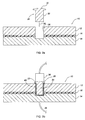
- Figure 2a is a schematic cross sectional view of the bonded metallic structure of figure 1a, illustrating in diagrammatic form the steps of forming a hole in the bonded metallic structure and inserting a slug therein;
- Figure 2b is a schematic cross sectional view of the bonded metallic structure of figure 1a, illustrating in diagrammatic form the step of passing current through the slug of sufficient intensity to bond the slug to the bonded metallic structure;
- Figure 3a is a schematic cross sectional view of the bonded metallic structure of figure 1a, illustrating in diagrammatic form the steps of forming a hole in the bonded metallic structure and inserting a slug therein;
- Figure 3b is a schematic cross sectional view of the bonded metallic structure of figure 1a, illustrating in diagrammatic form the step of passing a current through the slug of Figure 3a to bond the slug to the bonded metallic structure;
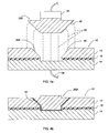
- Figure 4a is a schematic cross sectional view of the bonded metallic structure of figure 1a, illustrating in diagrammatic form the steps of forming a generally tapering hole and passing a current through a generally tapering slug to allow arcing to develop between the slug and the bonded metallic structure;
- Figure 4b is a schematic cross sectional view of the bonded metallic structure of figure 1a, illustrating in diagrammatic form the step inserting the slug of Figure 4a into the hole to bond the slug to the bonded metallic structure;
- Figure 5a is a schematic partial cross sectional view of the slug of figure 2a having a stud disposed thereon;
- Figure 5b is a schematic cross sectional view of the slug of figure 2a having a nut disposed thereon.
- the bonded metallic structure 10 includes a first metallic member 12 bonded to a second metallic member 14 by an adhesive layer 16.
- the first metallic member 12 may be, for example, an automotive body panel, while the second metallic member 14 may be, for example, the flange of a support member.
- the first and second metallic members are preferably formed from steel.
- the bonded metallic structure 10A includes a first metallic member 12A bonded to the second metallic member 14 by the adhesive layer 16.
- the first metallic member 12A is formed from a constrained layer viscoelastic laminate 18.
- the constrained layer viscoelastic laminate 18 includes a first and second metal layer 20 and 22, respectively.
- a viscoelastic layer 24 is disposed between and is generally coextensive with the first and second metal layers 20 and 22.
- the constrained layer viscoelastic laminate 18 may provide excellent sound and vibration damping qualities and is therefore used extensively in industry.
- first metallic member 12, 12A may become damaged and need to be removed from the second metallic member 14. Should this occur, the replaced adhesive layer 16 may not be as strong as that originally used; therefore, additional measures may need to be taken in order to adequately secure the first metallic member 12, 12A to the second metallic member 14. Methods of accomplishing this repair are outlined in illustrative form in Figures 2a through 4b.
- the bonded metallic structure 10 having a hole 26 defined therein.
- the hole 26 extends through the first metallic member 12 and at least partially into the second metallic member 14.
- the hole 26 may be formed by drilling, punching, piercing, or other hole forming methods known to those skilled in the art.
- the hole 26 is sufficiently configured to receive a slug 28.
- a slug 28 is preferably formed from metal and has a shaft portion 30 and a head portion 32. As the shaft portion 30 of the slug 28 is inserted into the hole 26, as indicated by arrow 34, the head portion 32 will abut the first metallic member 12 thereby limiting the travel of the slug 28 within the bonded metallic structure 10.
- an electrode 36 is pressed against the head portion 32, as shown in Figure 2b.
- a ground 38 is provided to the second metallic member 14 such that current will flow through the slug 28.
- the current is supplied to the slug 28 at a level or intensity sufficient to cause heating and localized melting at the interfaces formed by the slug 28 and the first and second metallic members 12 and 14. This localized melting forms a weld, indicated at 40, thereby securing or welding the first and second metallic members 12 and 14 to the slug 28.
- the head portion 32 is secured or welded to the first metallic member 12 providing an added measure of resistance to separation of the first and second metallic members 12 and 14.
- a coating of brazing material may be provided to the slug 28 to enable securing of the first and second metallic members 12 and 14 to the slug 28 through brazing.
- the head portion 32 may be any shape including circular, square, rectangular, cross shaped, oval, etc. Additionally, the head portion 32 may be used for joint strengthening purposes. For example, if the head portion 32 is formed with a generally oval shape the major axis of the oval may be oriented substantially perpendicular to the loading direction of the bonded metallic structure 10.
- Figure 3a illustrates the bonded metallic structure 10 shown in Figure 1a having a hole 26A extending substantially therethrough.
- the hole 26A is sufficiently configured to receive a slug 28A and as stated hereinabove may be formed by any method known to those skilled in the art.
- the slug 28A is preferably metal and is formed with substantially the same thickness as the bonded metallic structure 10 and is inserted into the hole 26A as indicated by arrow 42.
- Electrodes 36 are pressed against the slug 28A, as shown in Figure 3b.
- Current is supplied to the slug 28A at a level or intensity sufficient to cause heating and localized melting at the interfaces formed by the slug 28A and the first and second metallic members 12 and 14.
- This localized melting forms a weld, indicated at 44, thereby securing or welding the first and second metallic members 12 and 14 to the slug 28A.
- a coating of brazing material may be provided to the slug 28A to enable securing of the first and second metallic members 12 and 14 through brazing.
- Figure 4a illustrates the bonded metallic structure 10 shown in Figure 1a having a hole 26B formed within the first metallic member 12 and partially extending into the second metallic member 14.
- the hole 26B has generally tapering sidewalls 46 sufficiently configured to receive a slug 28B having complementary generally tapering sidewalls 48.
- the hole 26B may be formed by any means known to those skilled in the art.
- the slug 28B is positioned or spaced in close proximity to the hole 26B.
- An electrical current is provided to the slug 28B via the electrode 36 of sufficient intensity to induce a desired amount of arcing, indicated by dashed lines 50, between the slug 28B and the bonded metallic structure 10.
- the arcing generates heat in both the slug 28B and the bonded metallic structure such 10 that localized melting occurs.
- the slug 28B is then moved into touching contact with the bonded metallic 10 such that a weld 52, shown in Figure 4b, is formed thereby securing or welding the first and second metallic members 12 and 14 to the slug 28B.
- a coating of brazing material may be provided to the slug 28B to enable securing of the slug 28B to the first and second metallic members 12 and 14 through brazing.
- the hole 26B is shown in Figure 4a with generally tapering sidewalls 46, those skilled in the art will recognize that other geometries for the hole 26B and slug 28B may be envisioned in order to provide the desired arcing characteristics.
- the claimed methods are equally effective to repair the bonded metallic structure 10A of Figure 1b. That is, the claimed methods may be used effectively when one or both of the first and second metallic members 12 and 14 are formed from a constrained layer viscoelastic laminate 18 such as the first metallic member 12A of Figure 1b.
- the claimed methods are an effective means to secure the first metallic members 12, 12A with respect to the second metallic member 14 since the heat transferred to the bonded metallic structure 10 is localized and of short duration; therefore, the potential for damaging the adhesive layer 16 due to high thermal excursions is substantially reduced.
- the slugs 28, 28A, and 28B may be formed from high strength (i.e. high carbon equivalence) or low carbon steel.
- high strength i.e. high carbon equivalence
- low carbon steel the strength of the resulting weldment will increase.
- the slugs 28, 28A, and 28B are formed from low carbon steel, the strength of the resulting weldment will decrease due to carbon dilution. This may be beneficial to provide a "pull out" failure mode for the slugs 28, 28A, and 28B from the bonded metallic structure 10.
- Figure 5a illustrates the slug 28 having a stud 54 provided thereon.
- the stud 54 may be formed integrally with the slug 28, or may be mounted thereto.
- Figure 5b illustrates the slug 28 having a nut 56 provided thereon.
- the nut 56 may be formed integrally with the slug 28, or may be mounted thereto.
- the stud 54 and nut 56 may be employed as a mount or attachment point on the bonded metallic structure 10.
- the stud 54 and nut 56 may be provided on the studs 28A and 28B, while remaining within the scope of that which is claimed.
Landscapes
- Engineering & Computer Science (AREA)
- Mechanical Engineering (AREA)
- Physics & Mathematics (AREA)
- Plasma & Fusion (AREA)
- Connection Of Plates (AREA)
- Standing Axle, Rod, Or Tube Structures Coupled By Welding, Adhesion, Or Deposition (AREA)
- Resistance Welding (AREA)
Abstract
Description
- The present invention relates to a method for repairing bonded metallic structures.
- Modem automotive assembly techniques may include the use of so-called high-performance adhesives. These adhesives may be used to bond or adhere metallic members such as body panels and underbody support structures. The use of adhesives, while beneficial from a cost and mechanical performance standpoint, may pose problems when repairing damaged body panels. The facility performing the repair may not have the same type of adhesives available to the original equipment manufacturers and, as such, the bond between the body panel and support structure may be weaker than the original bond.
- For example, many adhesives used by the original equipment manufacturer require a baking step wherein the adhesive is subject to an elevated temperature for a predetermined amount of time to promote the curing of the adhesive. Repair facilities may utilize adhesives that cure at ambient air temperatures; therefore, the bond strength may be significantly lower than that of the original equipment manufacturer. As such, various methods have been developed to provide satisfactory bond strength between metallic members when the original equipment manufacturer adhesive technology is unavailable.
- A method of repairing a bonded metallic structure having a first metallic member bonded to a second metallic member is provided. The method includes the steps of: A) forming a hole, sufficiently configured to receive a slug, in at least one of the first metallic member and second metallic member; B) inserting the slug into the hole; and C) passing electrical current through the slug, the electrical current being of sufficient intensity to promote melting at the interface between the first metallic member, second metallic member, and the slug, thereby securing the first metallic member with respect to the second metallic member.
- The method may further include coating the slug with a brazing material prior to inserting the slug into the hole such that the first metallic member and second metallic member are brazed to the slug as current is passed through the slug. The hole may be formed by methods known in the art such as drilling, punching, piercing, etc. Additionally, the hole may extend through the first metallic member and at least partially through the second metallic member. Further, the hole may be formed with a generally tapering shape and the slug having a complementary generally tapering shape. Alternately, the slug may be generally cylindrical in shape and may have a shoulder portion defined thereon.
- In an alternate embodiment of the present invention, the method may include the steps of: A) forming a hole, sufficiently configured to receive a slug, in at least one of the first metallic member and second metallic member; B) positioning the slug near the hole; C) passing electrical current through the slug of sufficient intensity to promote arcing between the slug and the bonded metallic structure thereby melting at least a portion of the slug; and D) inserting at least the melted portion of the slug into the hole thereby securing the first metallic member with respect to the second metallic member.
- The above features and advantages and other features and advantages of the present invention are readily apparent from the following detailed description of the best modes for carrying out the invention when taken in connection with the accompanying drawings.
- Figure 1a is a schematic cross sectional view of a bonded metallic structure illustrating a first metallic member adhesively bonded to a second metallic member;
- Figure 1b is a schematic cross sectional view of an alternate embodiment of the bonded metallic structure of figure 1a illustrating a first metallic member formed from a constrained layer viscoelastic laminate.
- Figure 2a is a schematic cross sectional view of the bonded metallic structure of figure 1a, illustrating in diagrammatic form the steps of forming a hole in the bonded metallic structure and inserting a slug therein;
- Figure 2b is a schematic cross sectional view of the bonded metallic structure of figure 1a, illustrating in diagrammatic form the step of passing current through the slug of sufficient intensity to bond the slug to the bonded metallic structure;
- Figure 3a is a schematic cross sectional view of the bonded metallic structure of figure 1a, illustrating in diagrammatic form the steps of forming a hole in the bonded metallic structure and inserting a slug therein;
- Figure 3b is a schematic cross sectional view of the bonded metallic structure of figure 1a, illustrating in diagrammatic form the step of passing a current through the slug of Figure 3a to bond the slug to the bonded metallic structure;
- Figure 4a is a schematic cross sectional view of the bonded metallic structure of figure 1a, illustrating in diagrammatic form the steps of forming a generally tapering hole and passing a current through a generally tapering slug to allow arcing to develop between the slug and the bonded metallic structure;
- Figure 4b is a schematic cross sectional view of the bonded metallic structure of figure 1a, illustrating in diagrammatic form the step inserting the slug of Figure 4a into the hole to bond the slug to the bonded metallic structure; and
- Figure 5a is a schematic partial cross sectional view of the slug of figure 2a having a stud disposed thereon; and
- Figure 5b is a schematic cross sectional view of the slug of figure 2a having a nut disposed thereon.
- Referring to the drawings, wherein like reference numbers correspond to like or similar components throughout the several figures, there is shown schematically in Figure 1a, a bonded metallic structure, generally indicated at 10. The bonded
metallic structure 10 includes a firstmetallic member 12 bonded to a secondmetallic member 14 by anadhesive layer 16. The firstmetallic member 12 may be, for example, an automotive body panel, while the secondmetallic member 14 may be, for example, the flange of a support member. The first and second metallic members are preferably formed from steel. - Referring to Figure 1b there is shown an alternate embodiment of the bonded
metallic structure 10 of Figure 1a, generally indicated at 10A. The bondedmetallic structure 10A includes a firstmetallic member 12A bonded to the secondmetallic member 14 by theadhesive layer 16. The firstmetallic member 12A is formed from a constrained layerviscoelastic laminate 18. The constrained layerviscoelastic laminate 18 includes a first and second metal layer 20 and 22, respectively. Aviscoelastic layer 24 is disposed between and is generally coextensive with the first and second metal layers 20 and 22. Those skilled in the art will recognize that the constrained layerviscoelastic laminate 18 may provide excellent sound and vibration damping qualities and is therefore used extensively in industry. - It is envisioned at some point during the service life of the bonded
metallic structure metallic member metallic member 14. Should this occur, the replacedadhesive layer 16 may not be as strong as that originally used; therefore, additional measures may need to be taken in order to adequately secure the firstmetallic member metallic member 14. Methods of accomplishing this repair are outlined in illustrative form in Figures 2a through 4b. - Referring now to Figure 2a, there is shown the bonded
metallic structure 10 having ahole 26 defined therein. Thehole 26 extends through the firstmetallic member 12 and at least partially into the secondmetallic member 14. Thehole 26 may be formed by drilling, punching, piercing, or other hole forming methods known to those skilled in the art. Thehole 26 is sufficiently configured to receive aslug 28. Aslug 28 is preferably formed from metal and has ashaft portion 30 and ahead portion 32. As theshaft portion 30 of theslug 28 is inserted into thehole 26, as indicated byarrow 34, thehead portion 32 will abut the firstmetallic member 12 thereby limiting the travel of theslug 28 within the bondedmetallic structure 10. - Once the
slug 28 is seated within the bondedmetallic structure 10, anelectrode 36 is pressed against thehead portion 32, as shown in Figure 2b. Aground 38 is provided to the secondmetallic member 14 such that current will flow through theslug 28. The current is supplied to theslug 28 at a level or intensity sufficient to cause heating and localized melting at the interfaces formed by theslug 28 and the first and secondmetallic members metallic members slug 28. Additionally, thehead portion 32 is secured or welded to the firstmetallic member 12 providing an added measure of resistance to separation of the first and secondmetallic members slug 28 to enable securing of the first and secondmetallic members slug 28 through brazing. Those skilled in the art will recognize that thehead portion 32 may be any shape including circular, square, rectangular, cross shaped, oval, etc. Additionally, thehead portion 32 may be used for joint strengthening purposes. For example, if thehead portion 32 is formed with a generally oval shape the major axis of the oval may be oriented substantially perpendicular to the loading direction of the bondedmetallic structure 10. - Referring now to Figures 3a and 3b there is shown an alternate method of securing the first and second
metallic members metallic structure 10 shown in Figure 1a having ahole 26A extending substantially therethrough. Thehole 26A is sufficiently configured to receive aslug 28A and as stated hereinabove may be formed by any method known to those skilled in the art. Theslug 28A is preferably metal and is formed with substantially the same thickness as the bondedmetallic structure 10 and is inserted into thehole 26A as indicated byarrow 42. - Once the
slug 28A is seated within the bondedmetallic structure 10,electrodes 36 are pressed against theslug 28A, as shown in Figure 3b. Current is supplied to theslug 28A at a level or intensity sufficient to cause heating and localized melting at the interfaces formed by theslug 28A and the first and secondmetallic members metallic members slug 28A. A coating of brazing material may be provided to theslug 28A to enable securing of the first and secondmetallic members - Referring now to Figures 4a and 4b there is shown an alternate method of securing the first and second
metallic members metallic structure 10 shown in Figure 1a having ahole 26B formed within the firstmetallic member 12 and partially extending into the secondmetallic member 14. Thehole 26B has generally taperingsidewalls 46 sufficiently configured to receive aslug 28B having complementary generally taperingsidewalls 48. As stated hereinabove, thehole 26B may be formed by any means known to those skilled in the art. - As illustrated in Figure 4a, the
slug 28B is positioned or spaced in close proximity to thehole 26B. An electrical current is provided to theslug 28B via theelectrode 36 of sufficient intensity to induce a desired amount of arcing, indicated by dashedlines 50, between theslug 28B and the bondedmetallic structure 10. The arcing generates heat in both theslug 28B and the bonded metallic structure such 10 that localized melting occurs. Theslug 28B is then moved into touching contact with the bonded metallic 10 such that aweld 52, shown in Figure 4b, is formed thereby securing or welding the first and secondmetallic members slug 28B. A coating of brazing material may be provided to theslug 28B to enable securing of theslug 28B to the first and secondmetallic members hole 26B is shown in Figure 4a with generally taperingsidewalls 46, those skilled in the art will recognize that other geometries for thehole 26B and slug 28B may be envisioned in order to provide the desired arcing characteristics. - While the discussion of the joining methods presented herinabove illustrate the repair of the bonded
metallic structure 10 shown in Figure 1a, it should be noted that the claimed methods are equally effective to repair the bondedmetallic structure 10A of Figure 1b. That is, the claimed methods may be used effectively when one or both of the first and secondmetallic members layer viscoelastic laminate 18 such as the firstmetallic member 12A of Figure 1b. The claimed methods are an effective means to secure the firstmetallic members metallic member 14 since the heat transferred to the bondedmetallic structure 10 is localized and of short duration; therefore, the potential for damaging theadhesive layer 16 due to high thermal excursions is substantially reduced. - The
slugs slugs metallic members metallic member 14, formed from low carbon steel, the strength of the resulting weldment will increase. Alternately, when theslugs slugs metallic structure 10. - Figure 5a illustrates the
slug 28 having astud 54 provided thereon. Thestud 54 may be formed integrally with theslug 28, or may be mounted thereto. Figure 5b illustrates theslug 28 having anut 56 provided thereon. Thenut 56 may be formed integrally with theslug 28, or may be mounted thereto. Those skilled in the art will recognize that thestud 54 andnut 56 may be employed as a mount or attachment point on the bondedmetallic structure 10. Additionally, those skilled in the art will recognize that thestud 54 andnut 56 may be provided on thestuds - While the best modes for carrying out the invention have been described in detail, those familiar with the art to which this invention relates will recognize various alternative designs and embodiments for practicing the invention within the scope of the appended claims.
Claims (20)
- A method of repairing a bonded metallic structure having a first metallic member bonded to a second metallic member, the method comprising:forming a hole in at least one of the first metallic member and second metallic member, wherein said hole is sufficiently configured to receive a slug;inserting said slug into said hole; andpassing electrical current through said slug, wherein said electrical current is of sufficient intensity to promote melting at the interface between the first metallic member, second metallic member, and said slug, thereby securing the first metallic member with respect to the second metallic member.
- The method of claim 1, further comprising coating said slug with a brazing material prior to inserting said slug into said hole such that the first metallic member and second metallic member are brazed to said slug as said current is passed through said slug.
- The method of claim 1, further comprising forming said hole by one of punching, piercing, and drilling.
- The method of claim 1, wherein said slug has one of a stud and a nut provided thereon.
- The method of claim 1, wherein said hole extends through the first metallic member and at least partially through the second metallic member.
- The method of claim 1, wherein said hole is formed with a generally tapering shape and wherein said slug has a complementary generally tapering shape.
- The method of claim 1, wherein said slug is generally cylindrical in shape.
- The method of claim 1, further comprising providing a shoulder portion on said slug to limit the travel of said slug within said hole during insertion.
- The method of claim 1, wherein at least one of the first and second metallic members are formed from a constrained layer viscoelastic laminate.
- A method of repairing a bonded metallic structure having a first metallic member bonded to a second metallic member, the method comprising:forming a hole in at least one of the first metallic member and second metallic member, wherein said hole is sufficiently configured to receive a slug;positioning said slug near said hole;passing electrical current through said slug, wherein said electrical current is of sufficient intensity to promote arcing between said slug and the bonded metallic structure thereby melting at least a portion of said slug; andinserting at least said melted portion of said slug into said hole thereby securing the first metallic member with respect to the second metallic member.
- The method of claim 10, further comprising coating said slug with a brazing material such that the first metallic member and second metallic member are brazed to said slug as said current is passed through said slug.
- The method of claim 10, wherein said slug has one of a stud and a nut provided thereon.
- The method of claim 10, wherein said hole is formed with a generally tapering shape and wherein said slug has a complementary generally tapering shape.
- The method of claim 10, wherein at least one of the first and second metallic members are formed from a constrained layer viscoelastic laminate.
- A method of repairing a bonded metallic structure having a first metallic member bonded to a second metallic member, the method comprising:forming a hole in at least one the first metallic member and the second metallic member, wherein said hole is sufficiently configured to receive at least a portion of a slug; andsecuring said slug within said hole.
- The method of claim 15, wherein securing said slug within said hole includes:inserting said slug into said hole; andpassing electrical current through said slug, wherein said electrical current is of sufficient intensity to promote melting at the interface between said slug and the first metallic member and the second metallic member, thereby securing the first metallic member with respect to the second metallic member.
- The method of claim 15, wherein securing said slug within said hole includes:positioning said slug near said hole;passing electrical current through said slug, wherein said electrical current is of sufficient intensity to promote arcing between said slug and the bonded metallic structure thereby melting at least portions of said slug; andinserting said slug into said hole thereby securing the first metallic member with respect to the second metallic member.
- The method of claim 15, further comprising coating said slug with a brazing material
- The method of claim 17, wherein said hole is formed with a generally tapering shape and wherein said slug has a complementary generally tapering shape.
- The method of claim 15, wherein at least one of said another first metallic member and the second metallic member is formed from a constrained layer viscoelastic laminate.
Applications Claiming Priority (1)
| Application Number | Priority Date | Filing Date | Title |
|---|---|---|---|
| US11/539,969 US8466386B2 (en) | 2006-10-10 | 2006-10-10 | Method for repairing bonded metallic structures |
Publications (2)
| Publication Number | Publication Date |
|---|---|
| EP1911540A2 true EP1911540A2 (en) | 2008-04-16 |
| EP1911540A3 EP1911540A3 (en) | 2009-05-27 |
Family
ID=38984047
Family Applications (1)
| Application Number | Title | Priority Date | Filing Date |
|---|---|---|---|
| EP07019637A Withdrawn EP1911540A3 (en) | 2006-10-10 | 2007-10-08 | Method of repairing bonded metallic structures |
Country Status (4)
| Country | Link |
|---|---|
| US (1) | US8466386B2 (en) |
| EP (1) | EP1911540A3 (en) |
| JP (1) | JP2008155281A (en) |
| CN (1) | CN101219501B (en) |
Families Citing this family (15)
| Publication number | Priority date | Publication date | Assignee | Title |
|---|---|---|---|---|
| US9297795B2 (en) * | 2010-12-03 | 2016-03-29 | Todd Nicholas Bishop | Monitored filament insertion for resitivity testing |
| JP2013039596A (en) * | 2011-08-16 | 2013-02-28 | Chugoku Electric Power Co Inc:The | Repair method of metal component |
| US9463522B2 (en) | 2012-04-05 | 2016-10-11 | GM Global Technology Operations LLC | Drawn arc welding |
| US9328266B2 (en) | 2012-07-09 | 2016-05-03 | Gm Global Technology Operations, Llc | Method for mitigating cure shrinkage in high temperature-processed thermosetting adhesives and SMC |
| TW201438837A (en) * | 2013-02-27 | 2014-10-16 | Berndorf Band Gmbh | Method for repairing damage to a metal substrate |
| JP6509205B2 (en) | 2013-06-26 | 2019-05-08 | アーコニック インコーポレイテッドArconic Inc. | Resistance welding fastener, apparatus and method |
| NL1040411C2 (en) * | 2013-09-26 | 2015-03-30 | Pul Isoleermaterialenind Bv | METHOD FOR MANUFACTURING A LAMINARY CONSTRUCTION PLATE |
| JP6252747B2 (en) * | 2013-11-22 | 2017-12-27 | ポップリベット・ファスナー株式会社 | Joining apparatus and joining method |
| BR112016017920B1 (en) | 2014-02-03 | 2021-01-26 | Arconic Inc. | fastening element for fixing a first electrically conductive material to a second electrically conductive material and method for attaching a plurality of adjacent layers of a first electrically conductive material to a second electrically conductive material |
| US10384296B2 (en) | 2014-12-15 | 2019-08-20 | Arconic Inc. | Resistance welding fastener, apparatus and methods for joining similar and dissimilar materials |
| KR102319841B1 (en) | 2015-09-16 | 2021-10-29 | 하우매트 에어로스페이스 인코포레이티드 | Rivet feeding apparatus |
| ES2822908T3 (en) * | 2015-10-05 | 2021-05-05 | Outokumpu Oy | Method of manufacturing a welded component and component usage |
| US10593034B2 (en) | 2016-03-25 | 2020-03-17 | Arconic Inc. | Resistance welding fasteners, apparatus and methods for joining dissimilar materials and assessing joints made thereby |
| CN109590674A (en) * | 2018-10-24 | 2019-04-09 | 百路达(厦门)工业有限公司 | A kind of deep hole processing method of metalwork |
| US20240051060A1 (en) * | 2022-08-15 | 2024-02-15 | GM Global Technology Operations LLC | Method for joining an aluminum component to a steel component using a welded rivet |
Citations (1)
| Publication number | Priority date | Publication date | Assignee | Title |
|---|---|---|---|---|
| US20050173492A1 (en) | 2004-02-05 | 2005-08-11 | Workman David P. | Method for repairing defects in a metallic substrate using welding |
Family Cites Families (21)
| Publication number | Priority date | Publication date | Assignee | Title |
|---|---|---|---|---|
| US2569059A (en) * | 1947-12-18 | 1951-09-25 | Union Carbide & Carbon Corp | Welded rivet construction for electrical brushes and contacts |
| US3655424A (en) * | 1968-05-24 | 1972-04-11 | Massachusetts Inst Technology | Adhesive tape |
| GB1429630A (en) * | 1972-11-24 | 1976-03-24 | Lucas Bateries Ltd Joseph | Method of repairing a defective interconnection between battery plates in a pair of adjacent cell compartments of an electric storage battery |
| JPS58110171A (en) | 1981-12-24 | 1983-06-30 | Nippon Sutatsudouerudeingu Kk | Brazing and fusion-welding method for metallic plate and metallic cylindrical body |
| DE8327618U1 (en) * | 1983-09-26 | 1984-05-24 | Siku GmbH Metall- und Kunststoffwarenfabrik, 6221 Rickenbach | TOOL, PREFERABLY CHISEL |
| GB2198667B (en) * | 1986-12-20 | 1991-08-07 | Refurbished Turbine Components | Parts for and methods of repairing machines |
| JPH01182035A (en) | 1988-01-18 | 1989-07-19 | Nisshin Steel Co Ltd | Preparation of electric resistance-weldable resin laminated composite metal plate |
| US5070775A (en) * | 1991-01-09 | 1991-12-10 | Bottomline Management, Inc. | Removable cooking surface for the movable platen of a two-sided cooking device |
| CZ231092A3 (en) | 1991-08-02 | 1993-02-17 | Emhart Inc | Arc welded joint between a carrier and a detail attached fixedly thereto |
| DE4319533A1 (en) * | 1993-06-12 | 1994-12-15 | Hoechst Ceram Tec Ag | Internal soldering in metal-ceramic composites |
| US5349737A (en) * | 1993-11-30 | 1994-09-27 | Long James A | Method for separating spot-welded sheet metal parts |
| JP2909482B2 (en) | 1994-06-02 | 1999-06-23 | 鹿島建設株式会社 | Steel plate welding method |
| JPH0929440A (en) * | 1995-07-20 | 1997-02-04 | Japan Drive-It Co Ltd | Method for welding deck plate |
| CH690029A5 (en) * | 1995-10-11 | 2000-03-31 | Bloesch W Ag | Fusible substrate coating, especially for producing liquid- and gas-tight brazed joints in the watch and jewelry industries, comprises layers of different elements and-or alloys which form an eutectic melt |
| JPH09285865A (en) | 1996-04-22 | 1997-11-04 | Toyota Motor Corp | Arc welding method for plate member and welding stud |
| JP3617585B2 (en) | 1997-03-28 | 2005-02-09 | 株式会社神戸製鋼所 | Method of lining titanium or titanium alloy material to steel |
| US6454156B1 (en) * | 2000-06-23 | 2002-09-24 | Siemens Westinghouse Power Corporation | Method for closing core printout holes in superalloy gas turbine blades |
| KR100890715B1 (en) * | 2000-11-01 | 2009-03-27 | 소니 가부시끼 가이샤 | Battery, Method for Manufacturing Battery, Method for Manufacturing Weld and Pedestal |
| US7000303B2 (en) * | 2002-10-24 | 2006-02-21 | The Boeing Company | Method of repairing a crack in a component utilizing friction stir welding |
| JP2004195525A (en) * | 2002-12-20 | 2004-07-15 | Hitachi Ltd | Friction stir welding method |
| GB2414213B (en) * | 2004-05-21 | 2008-11-12 | Intelligent Engineering | Improved structural sandwich plate members |
-
2006
- 2006-10-10 US US11/539,969 patent/US8466386B2/en not_active Expired - Fee Related
-
2007
- 2007-10-08 EP EP07019637A patent/EP1911540A3/en not_active Withdrawn
- 2007-10-10 CN CN200710194427XA patent/CN101219501B/en not_active Expired - Fee Related
- 2007-10-10 JP JP2007264339A patent/JP2008155281A/en active Pending
Patent Citations (1)
| Publication number | Priority date | Publication date | Assignee | Title |
|---|---|---|---|---|
| US20050173492A1 (en) | 2004-02-05 | 2005-08-11 | Workman David P. | Method for repairing defects in a metallic substrate using welding |
Also Published As
| Publication number | Publication date |
|---|---|
| JP2008155281A (en) | 2008-07-10 |
| US8466386B2 (en) | 2013-06-18 |
| CN101219501A (en) | 2008-07-16 |
| EP1911540A3 (en) | 2009-05-27 |
| US20080085568A1 (en) | 2008-04-10 |
| CN101219501B (en) | 2011-04-20 |
Similar Documents
| Publication | Publication Date | Title |
|---|---|---|
| EP1911540A2 (en) | Method of repairing bonded metallic structures | |
| US9012029B2 (en) | Method of bonding panels of dissimilar material and bonded structure | |
| CN102673660B (en) | Automobile-used board component and the method being connected automobile-used board component | |
| JP6260592B2 (en) | Dissimilar material joining structure and manufacturing method of dissimilar material joined body | |
| CN110102866A (en) | Melting welding ultrasonic wave increasing material manufacturing transition for dissimilar metal part | |
| US8544715B2 (en) | Repairing a friction stir welded assembly | |
| KR20040036544A (en) | Method of repairing a crack in a component utilizing friction stir welding | |
| US11607751B2 (en) | Laminate including weldable regions | |
| JP2015167972A (en) | Manufacturing method of dissimilar joint | |
| KR20190017124A (en) | Adhering structure and method of different kinds materials | |
| US20180142771A1 (en) | System of components having wire weld joint and a method of joining a system of components including a cast iron component | |
| JP2002224857A (en) | Joining structure and joining method between hollow members made of respectively different kinds of metal | |
| CN107735581A (en) | Method for connecting components and component composite structure | |
| CN103958267A (en) | Fiber-reinforced resin structure | |
| US20080087650A1 (en) | Method for single side welding of laminate steel | |
| CN101743388B (en) | Exhaust system pipe with customized wall thickness | |
| CN110582650B (en) | Joint body, automobile seat frame, and joining method | |
| JP2017070995A (en) | Method for joining heterogeneous metal plate and component for joining heterogeneous metal plate | |
| JP6591030B2 (en) | Joint and automobile seat frame | |
| JP6533654B2 (en) | Electric welding equipment | |
| US20220097165A1 (en) | Conductive sheet as current conductor to spot weld steel | |
| CN101131190A (en) | Cylinder device and manufacturing method thereof | |
| CN205800191U (en) | A kind of plastic plate and the resistance spot welding structure of aluminium sheet | |
| EP1410869B1 (en) | Weld bracket to sheet metal construction and method for coupling a weld bracket to a sheet metal component | |
| JPH0636990B2 (en) | Welding method with damping steel plate |
Legal Events
| Date | Code | Title | Description |
|---|---|---|---|
| PUAI | Public reference made under article 153(3) epc to a published international application that has entered the european phase |
Free format text: ORIGINAL CODE: 0009012 |
|
| AK | Designated contracting states |
Kind code of ref document: A2 Designated state(s): AT BE BG CH CY CZ DE DK EE ES FI FR GB GR HU IE IS IT LI LT LU LV MC MT NL PL PT RO SE SI SK TR |
|
| AX | Request for extension of the european patent |
Extension state: AL BA HR MK RS |
|
| PUAL | Search report despatched |
Free format text: ORIGINAL CODE: 0009013 |
|
| AK | Designated contracting states |
Kind code of ref document: A3 Designated state(s): AT BE BG CH CY CZ DE DK EE ES FI FR GB GR HU IE IS IT LI LT LU LV MC MT NL PL PT RO SE SI SK TR |
|
| AX | Request for extension of the european patent |
Extension state: AL BA HR MK RS |
|
| 17P | Request for examination filed |
Effective date: 20091127 |
|
| AKX | Designation fees paid |
Designated state(s): DE |
|
| 17Q | First examination report despatched |
Effective date: 20100209 |
|
| RAP1 | Party data changed (applicant data changed or rights of an application transferred) |
Owner name: GM GLOBAL TECHNOLOGY OPERATIONS LLC |
|
| STAA | Information on the status of an ep patent application or granted ep patent |
Free format text: STATUS: THE APPLICATION IS DEEMED TO BE WITHDRAWN |
|
| 18D | Application deemed to be withdrawn |
Effective date: 20130316 |