EP1911536A1 - Hot forging equipment - Google Patents
Hot forging equipment Download PDFInfo
- Publication number
- EP1911536A1 EP1911536A1 EP06747272A EP06747272A EP1911536A1 EP 1911536 A1 EP1911536 A1 EP 1911536A1 EP 06747272 A EP06747272 A EP 06747272A EP 06747272 A EP06747272 A EP 06747272A EP 1911536 A1 EP1911536 A1 EP 1911536A1
- Authority
- EP
- European Patent Office
- Prior art keywords
- hot forging
- cooling
- forged product
- hot
- forging
- Prior art date
- Legal status (The legal status is an assumption and is not a legal conclusion. Google has not performed a legal analysis and makes no representation as to the accuracy of the status listed.)
- Withdrawn
Links
Images


Classifications
-
- B—PERFORMING OPERATIONS; TRANSPORTING
- B21—MECHANICAL METAL-WORKING WITHOUT ESSENTIALLY REMOVING MATERIAL; PUNCHING METAL
- B21J—FORGING; HAMMERING; PRESSING METAL; RIVETING; FORGE FURNACES
- B21J1/00—Preparing metal stock or similar ancillary operations prior, during or post forging, e.g. heating or cooling
- B21J1/06—Heating or cooling methods or arrangements specially adapted for performing forging or pressing operations
-
- C—CHEMISTRY; METALLURGY
- C21—METALLURGY OF IRON
- C21D—MODIFYING THE PHYSICAL STRUCTURE OF FERROUS METALS; GENERAL DEVICES FOR HEAT TREATMENT OF FERROUS OR NON-FERROUS METALS OR ALLOYS; MAKING METAL MALLEABLE, e.g. BY DECARBURISATION OR TEMPERING
- C21D8/00—Modifying the physical properties of ferrous metals or ferrous alloys by deformation combined with, or followed by, heat treatment
-
- B—PERFORMING OPERATIONS; TRANSPORTING
- B21—MECHANICAL METAL-WORKING WITHOUT ESSENTIALLY REMOVING MATERIAL; PUNCHING METAL
- B21J—FORGING; HAMMERING; PRESSING METAL; RIVETING; FORGE FURNACES
- B21J5/00—Methods for forging, hammering, or pressing; Special equipment or accessories therefor
-
- B—PERFORMING OPERATIONS; TRANSPORTING
- B21—MECHANICAL METAL-WORKING WITHOUT ESSENTIALLY REMOVING MATERIAL; PUNCHING METAL
- B21J—FORGING; HAMMERING; PRESSING METAL; RIVETING; FORGE FURNACES
- B21J9/00—Forging presses
- B21J9/02—Special design or construction
- B21J9/022—Special design or construction multi-stage forging presses
-
- B—PERFORMING OPERATIONS; TRANSPORTING
- B21—MECHANICAL METAL-WORKING WITHOUT ESSENTIALLY REMOVING MATERIAL; PUNCHING METAL
- B21K—MAKING FORGED OR PRESSED METAL PRODUCTS, e.g. HORSE-SHOES, RIVETS, BOLTS OR WHEELS
- B21K1/00—Making machine elements
- B21K1/06—Making machine elements axles or shafts
- B21K1/08—Making machine elements axles or shafts crankshafts
-
- B—PERFORMING OPERATIONS; TRANSPORTING
- B21—MECHANICAL METAL-WORKING WITHOUT ESSENTIALLY REMOVING MATERIAL; PUNCHING METAL
- B21K—MAKING FORGED OR PRESSED METAL PRODUCTS, e.g. HORSE-SHOES, RIVETS, BOLTS OR WHEELS
- B21K1/00—Making machine elements
- B21K1/28—Making machine elements wheels; discs
- B21K1/40—Making machine elements wheels; discs hubs
-
- B—PERFORMING OPERATIONS; TRANSPORTING
- B21—MECHANICAL METAL-WORKING WITHOUT ESSENTIALLY REMOVING MATERIAL; PUNCHING METAL
- B21K—MAKING FORGED OR PRESSED METAL PRODUCTS, e.g. HORSE-SHOES, RIVETS, BOLTS OR WHEELS
- B21K29/00—Arrangements for heating or cooling during processing
-
- C—CHEMISTRY; METALLURGY
- C21—METALLURGY OF IRON
- C21D—MODIFYING THE PHYSICAL STRUCTURE OF FERROUS METALS; GENERAL DEVICES FOR HEAT TREATMENT OF FERROUS OR NON-FERROUS METALS OR ALLOYS; MAKING METAL MALLEABLE, e.g. BY DECARBURISATION OR TEMPERING
- C21D1/00—General methods or devices for heat treatment, e.g. annealing, hardening, quenching or tempering
- C21D1/18—Hardening; Quenching with or without subsequent tempering
-
- C—CHEMISTRY; METALLURGY
- C21—METALLURGY OF IRON
- C21D—MODIFYING THE PHYSICAL STRUCTURE OF FERROUS METALS; GENERAL DEVICES FOR HEAT TREATMENT OF FERROUS OR NON-FERROUS METALS OR ALLOYS; MAKING METAL MALLEABLE, e.g. BY DECARBURISATION OR TEMPERING
- C21D1/00—General methods or devices for heat treatment, e.g. annealing, hardening, quenching or tempering
- C21D1/62—Quenching devices
- C21D1/667—Quenching devices for spray quenching
-
- C—CHEMISTRY; METALLURGY
- C21—METALLURGY OF IRON
- C21D—MODIFYING THE PHYSICAL STRUCTURE OF FERROUS METALS; GENERAL DEVICES FOR HEAT TREATMENT OF FERROUS OR NON-FERROUS METALS OR ALLOYS; MAKING METAL MALLEABLE, e.g. BY DECARBURISATION OR TEMPERING
- C21D7/00—Modifying the physical properties of iron or steel by deformation
- C21D7/13—Modifying the physical properties of iron or steel by deformation by hot working
-
- C—CHEMISTRY; METALLURGY
- C22—METALLURGY; FERROUS OR NON-FERROUS ALLOYS; TREATMENT OF ALLOYS OR NON-FERROUS METALS
- C22C—ALLOYS
- C22C38/00—Ferrous alloys, e.g. steel alloys
- C22C38/02—Ferrous alloys, e.g. steel alloys containing silicon
-
- C—CHEMISTRY; METALLURGY
- C22—METALLURGY; FERROUS OR NON-FERROUS ALLOYS; TREATMENT OF ALLOYS OR NON-FERROUS METALS
- C22C—ALLOYS
- C22C38/00—Ferrous alloys, e.g. steel alloys
- C22C38/04—Ferrous alloys, e.g. steel alloys containing manganese
-
- C—CHEMISTRY; METALLURGY
- C22—METALLURGY; FERROUS OR NON-FERROUS ALLOYS; TREATMENT OF ALLOYS OR NON-FERROUS METALS
- C22C—ALLOYS
- C22C38/00—Ferrous alloys, e.g. steel alloys
- C22C38/06—Ferrous alloys, e.g. steel alloys containing aluminium
Definitions
- the present invention relates to a hot forging facility for manufacturing various hot forged products, of which typical examples includes machine structural components represented by, for example, steel-using automobile components such as suspension components including, for example, constant-velocity universal joints and hubs, and engine components such as crankshafts.
- machine structural components represented by, for example, steel-using automobile components such as suspension components including, for example, constant-velocity universal joints and hubs, and engine components such as crankshafts.
- steel products for the use of, for example, automobile axle unit and engine components are each manufactured in the manner that the product is hot forged, and thereafter is finished by a machining process (or, "machined and finished,” herebelow).
- a manufacturing process for such a component is disclosed in, for example, Non-Patent Publication 1 (*1) listed below.
- the manufacturing process is carried out by processing steps representative of forging production processing steps. More specifically, a material is machined and heated, and thereafter, the thus-processed material is shaped or formed by a forging step, and by necessity, the formed material is heat treated.
- Patent Publication 1 (*2) listed below, as a technique for increasing the fatigue strengths of hot forged products, there is disclosed a manufacturing method for a high fatigue strength hot forged product. According to the method, the entirety of a forged product is hardened or quenched after hot forging, and further, the matrix thereof is precipitation hardened by tempering processing.
- Patent Publication 2 (*3) listed below discloses a cooling apparatus operating such that cooling rate nonuniformity in the entirety of a forged product is eliminated, thereby to control the overall cooling rate for the product.
- the component (product) itself is directly cooled after hot forging, such that the hardness of the entirety of the component is increased, and hence the workability of an area not requiring fatigue strength is reduced.
- a machine structural component for the above-described use is manufactured in the manner that the material is formed by hot forging into substantially the product shape, and thereafter, the entire surface of the hot forged product is machined and finished.
- the machining process and surface abrading are indispensable.
- the hardness of the entirety of the component is increased, reduction in machinability inevitably poses a significant problem.
- a manufacturing facility for implementing the above-described method requires a heating facility to provide separate quenching for the precipitation hardening treatment. As such, the facility is not preferable even from the viewpoint of energy saving.
- Patent Publication 2 controls the cooling rate of the entirety of the workpiece, such that reduction in machinability poses a significant problem.
- an object of the present invention is to provide a hot forging facility enabling manufacturing of a hot forged product excellent in fatigue properties and cold workability.
- the present invention is based on the knowledge described above.
- essential configurations of the present invention are as follows.
- a facility for securely implementing the manufacture of a hot forged product excellent in fatigue properties and cold workability can be provided.
- FIGS. 3 to 5 Reference numerals in FIGS. 3 to 5 are as follows:
- a hardened area is provided in a specifically fatigue-strength required area of a forged product by performing partial cooling after hot forging, and other areas are remained as an un-hardened area, in which a Vickers hardness V 1 of the hardened area, particularly, on a surface and a Vickers hardness V 2 of the un-hardened area satisfy an expression: ( V 1 - V 2 ) / V 2 : 0.1 ⁇ 0.8 More specifically, when the ratio "(V 1 -V 2 )/V 2 " is less than 0.1, a strength increase of the hardened area is insufficient, such that sufficient strength improvement effectiveness cannot be obtained.
- the ratio "(V 1 -V 2 )/V 2 " exceeds 0.8, then the hardness is excessively increased, thereby significantly reducing cold workability, such as machinability.
- the hardness ratio "(V 1 -V 2 )/V 2 " is set to 0.8 or less.
- An optimal range of the ratio is from 0.2 to 0.6.
- the hardened area having the hardness difference is structured from martensite and/or bainite.
- the un-hardened area is primarily structured from ferrite and/or pearlite, but, depending on the case, can partly be mixed with bainite.
- hot forged product is obtained through the direct partial quenching after hot forging, and then is formed into a machine structural component through a mechanical finishing process.
- hot forging refers to the step of performing forging by heating the material to a temperature of A c3 or higher.
- the steel material is heated and fed into the hot forging apparatus.
- a partial cooling process is performed to cool down the forged product having been obtained as described above, from a temperature of A c3 or higher to a temperature of Ac1-150°C or lower at a rate of 20°C/s.
- an area of the product required to have a high fatigue strength after hot forging is cooled down from a temperature of A c3 or higher to a temperature of A c1 -150°C or lower at a cooling rate of 20°C/s.
- partial cooling after hot forging is performed within the temperature range of from A c3 or higher to A c1 -150°C or lower. It is indispensable to perform cooling from A c3 or higher in order to obtain a sufficient heat recuperation effect after cooling; and cooling is performed to A c1 -150°C or lower is to suppress ferrite development or transformation.
- the cooling rate within the temperature range is set to the cooling rate of 20°C/s in order to transform the structure into martensite and/or bainite while suppressing the ferrite transformation.
- the component is quenched by heat recuperation in accordance with the holding heat of the component within the temperature range not continually exceeding the A C1 point. More specifically, when the quenching temperature associated with the heat recuperation exceeds the A C1 point, the structure formed by partial quenching is retransformed into an austenite structure and is transformed into a ferrite-pearlite structure. To prevent this, it is important to cause the component to be quenched within the temperature range not exceeding the A C1 point.
- FIG. 1 shows a temperature history in the event of heat recuperation of a partially cooled area.
- an average temperature T n (K) in each time period ⁇ t n is obtained from a cooling curve after stop of cooling, and the resultant value is adapted in expression (1), whereby the parameter H is defined.
- the temperature T n in the stage of self-tempering continually varies, the temperature is obtained by assuming ⁇ t n to 0.5 seconds or less.
- FIG. 2 shows the relationship between the ratio "(V 1 -V 2 )/V 2 " and the parameter H.
- the parameter H and the hardness ratio are in a good interrelationship.
- the hardness ratio "(V 1 -V 2 )/V 2 " exceeds 0.8, therefore posing the problem with the machinability.
- the parameter H exceeds 85, the component is excessively softened to the extend that the ratio "(V 1 -V 2 )/V 2 " is less than 0.1 at which fatigue strength improvement effects cannot be obtained.
- partial cooling after hot forging has to be appropriately performed, preferably, in accordance with the parameter H.
- a hot forging facility for obtaining the product will be described in detail herebelow with reference to FIG. 3 .
- numeral 1 represents a heating furnace for heating the steel material.
- a hot forging apparatus 4 is disposed on a transport line 3 of a heated steel material 2 extending toward an outlet side of the heating furnace 1.
- a partially cooling apparatus 5 is disposed in a position along the transport line 3 on an exit side of the hot forging apparatus 4.
- the heated steel material 2 is formed into a desired shape by die forging.
- a steel material 2 shown in FIG. 4(a) is formed into a forged product 20 having a pre-finishing product shape.
- a specified area of the forged product 20 is cooled in the partially cooling apparatus 5 disposed on the exit side of the hot forging apparatus 4.
- a plurality of nozzles 5a are provided towards the forged product 20 in a plurality of circumferentially equi-sectional positions of two portions, namely upper and lower portions, of the forged product 20. Cooling liquid is sprayed from the nozzles 5a towards, for example, flange base portions 20a of the forged product 20, thereby making it possible to perform localized cooling of the flange base portions 20a.
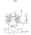
- a partially cooling apparatus shown in FIG. 5 includes a turn table 6 that is used for placing the forged product 20 and that is turnable by a motor 8.
- the plurality of nozzles 5a are positioned and fixed to inject cooling water to the flange base portions 20a placed on the table 6.
- the nozzles 5a are each fluidly connected to a cooling water feed pipe 12.
- the cooling water feed pipe 12 is provided to include a booster pump 11 for feeding the cooling water, a flow regulation valve 10 for controlling the volume of injection, and a flowmeter 9 for monitoring the flow.
- upper and lower cooling water partition plates 7a and 7b, respectively, are provided on upper and lower sides of the respective nozzle 5a.
- the respective plate is thus provided to locally cool only the flange base portions 20a of the forged product 20 and to thereby prevent other areas from being cooled.
- Either of the upper or lower cooling water partition plates 7a and 7b is formed from an annular partition plate to be capable of preventing even leakage of the cooling water to a not-to-be-cooled area of the forged product 20. Further, even for the turn table 6, a ceramic table is used to prevent dissipation of heat of a portion being in contact with the rotary table 6 of the forged product 20.
- the partially cooling apparatus when the cooling water is injected from the nozzles 5a while the turn table 6 is being turned, only the flange base portions 20a is cooled, but the other areas are not forcedly cooled. Consequently, only a locally cooled area, that is, the flange base portions 20a in the present example, can be quenched. After stop of cooling, then self-tempering is effected using heat transferred from non-locally cooled areas.
- partial cooling is performed, preferably, by using the parameter H described above.
- radiational cooling is effected.
- the radiational cooling can be effected either in a bucket (not shown) disposed to a terminal end of the transport line 3 or on the transport line 3.
- a plurality of partially cooling apparatuses 5 can be disposed along the transport line 3.
- a plurality of forged products can be partially cooled at substantially the same time, such that the partial cooling process can be implemented corresponding to the forging rate in the same line.
- the nozzles 5a may be either a plurality of openings provided on an inner side of a ringular pipe or circumferential slit nozzles.
- a non-turnable table may be used instead of the turn table 6.
- the turn table 6 it is preferable that the turn table 6 be used to further improve uniformity.
- partition plate 7a is provided corresponding to an allowable level of the degree of temperature fall in the not-to-be-cooled area, but is not indispensable.
- the partially cooling apparatus 5 is disposed on the side downstream of the forging apparatus.
- the partially cooling apparatus 5 may be provided inside of the forging apparatus to be able to effect cooling immediately after forging.
- the configuration may be such that, when performing forging at multiple passes, cooling is effected in any inter-pass stage.
- partial cooling localized to flange base portions 20a was effected by injecting the cooling water at a flow range of 10 ⁇ 201/min, and then was subjected to radiational cooling.
- the start temperature of the partially cooled area was set to 780 ⁇ 1150°C.
- the respective hot forged product thus obtained was subjected structure observation, hardness measurement, and machining testing.
- forged products were manufactured through a hot forging and air cooling process and hot forging and entire tempering process that have been conventionally generally used. In this case, after entire quenching, a tempering process was performed to satisfy a condition of "600°C (tempering temperature) ⁇ 1 hr.”
- structure observation was carried in such a manner that structure observation samples, respectively, were cut out from a flange base portion 20a and axial end portion 20b of the respective hot forged product obtained, and "3 vol.% nital" etched microstructures thereof were observed using an optical microscope and an electronic microscope.
- Vickers hardness measurement was carried out in such a manner that the Vickers hardness was measured at a 1-mm portions below a skin of each of the flange base portion 20a and the axial end portion 20b by applying a load of 300 g.
- Machinability by machining (cutting) testing was evaluated by outer-circumference machining. More specifically, machining was carried with a carbide tool P10 at a cutting speed of 200 m/min, a cutting depth of 0.25 mm, and a feed of 0.5 mm/rev by spraying a lubricant, and the machinability was evaluated in terms of a time period required for machining the entirety of the respective component. More specifically, evaluation was made in terms of "(t2 - t1)/t1," where t2 is the required time relative to a time period t1 required for machining the respective material subjected to the conventional hot forging and air cooling process.
Landscapes
- Chemical & Material Sciences (AREA)
- Engineering & Computer Science (AREA)
- Mechanical Engineering (AREA)
- Materials Engineering (AREA)
- Metallurgy (AREA)
- Organic Chemistry (AREA)
- Crystallography & Structural Chemistry (AREA)
- Thermal Sciences (AREA)
- Physics & Mathematics (AREA)
- Forging (AREA)
- Heat Treatment Of Articles (AREA)
- Heat Treatment Of Steel (AREA)
- Heat Treatments In General, Especially Conveying And Cooling (AREA)
Abstract
Description
- The present invention relates to a hot forging facility for manufacturing various hot forged products, of which typical examples includes machine structural components represented by, for example, steel-using automobile components such as suspension components including, for example, constant-velocity universal joints and hubs, and engine components such as crankshafts.
- According to a general practice, steel products for the use of, for example, automobile axle unit and engine components, are each manufactured in the manner that the product is hot forged, and thereafter is finished by a machining process (or, "machined and finished," herebelow). A manufacturing process for such a component is disclosed in, for example, Non-Patent Publication 1 (*1) listed below. The manufacturing process is carried out by processing steps representative of forging production processing steps. More specifically, a material is machined and heated, and thereafter, the thus-processed material is shaped or formed by a forging step, and by necessity, the formed material is heat treated.
- Recently, it is increasingly demanded that products for the above-described use be improved in fatigue strength for implementation of, for example, compactness and thinning for weight reduction of automobiles using those products.
- In Patent Publication 1 (*2) listed below, as a technique for increasing the fatigue strengths of hot forged products, there is disclosed a manufacturing method for a high fatigue strength hot forged product. According to the method, the entirety of a forged product is hardened or quenched after hot forging, and further, the matrix thereof is precipitation hardened by tempering processing.
- Further, Patent Publication 2 (*3) listed below discloses a cooling apparatus operating such that cooling rate nonuniformity in the entirety of a forged product is eliminated, thereby to control the overall cooling rate for the product.
- (*1) Non-Patent Publication 1: "Plastic Processing Technology Series 4: Forging"; The Japan Society for Technology of Plasticity, published by Corona
- (*2) Patent Publication 1:
Japanese Patent No. 3100492 - (*3) Patent Publication 2:
Japanese Patent No. 2936198 - However, according to the method disclosed in
Patent Publication 1, the component (product) itself is directly cooled after hot forging, such that the hardness of the entirety of the component is increased, and hence the workability of an area not requiring fatigue strength is reduced. More specifically, according to a general practice, a machine structural component for the above-described use is manufactured in the manner that the material is formed by hot forging into substantially the product shape, and thereafter, the entire surface of the hot forged product is machined and finished. As such, in the manufacture of a machine structural component of the above-described type, the machining process and surface abrading are indispensable. However, in the event that the hardness of the entirety of the component is increased, reduction in machinability inevitably poses a significant problem. - In addition, a manufacturing facility for implementing the above-described method requires a heating facility to provide separate quenching for the precipitation hardening treatment. As such, the facility is not preferable even from the viewpoint of energy saving.
- Similarly, the technique described in
Patent Publication 2 controls the cooling rate of the entirety of the workpiece, such that reduction in machinability poses a significant problem. - Under these circumstances, for the facility described in any one of
Patent Publications - Accordingly, an object of the present invention is to provide a hot forging facility enabling manufacturing of a hot forged product excellent in fatigue properties and cold workability.
- In order to achieve the object, the inventors made extensive study and research, particularly, about execution of partial cooling after hot forging, and resultantly obtained knowledges (I) to (III) below.
- (I) When a hardness increase rate of an area of a hot forged product reaches 10% or higher after partial cooling of a specifically fatigue-strength required area, the fatigue strength of the product as a component can be increased by 20% or higher.
- (II) An area partially quenched by partial cooling is self-tempered by the quantity of holding heat of a non-cooled area. As a consequence, effectiveness equivalent to the effectiveness after the tempering process conventionally performed as the additional processing step can be obtained. In order to obtain the effectiveness, the tempering process has to be performed to satisfy a specific parameter.
- (III) Consequently, the forged product does not have to be additionally tempered after being cooled to the ambient temperature, therefore making it possible to manufacture a high fatigue strength component at low cost.
- Further, in order to practical enforcement of the technique in accordance with the above-described knowledge, the inventors made extensive investigation regarding the configuration of a facility enabling manufacture on an industrial scale, and as a consequence, the inventors have developed the invention.
- The present invention is based on the knowledge described above.
- More specifically, essential configurations of the present invention are as follows.
- (1) In a hot forging facility wherein a heating furnace for heating a steel material and a hot forging apparatus for performing forging of the heated steel material are sequentially arranged on a transport line, a partially cooling apparatus/apparatuses for partially cooling a forged product after hot forging is provided inside of and/or on an exit side of the hot forging apparatus.
- (2) In a hot forging facility as described in (1), the partially cooling apparatus includes a nozzle for spraying cooling liquid towards a part of the forged product.
- (3) In a hot forging facility as described in (1) or (2), at least one unit of the partially cooling apparatus is provided in a position along the transport line on an exit side of the hot forging apparatus.
- (4) In a hot forging facility as described in any one of (1) to (3), a plurality of the partial cooling apparatuses are provided in positions along the transport line on an exit side of the hot forging apparatus.
- According to the present invention, a facility for securely implementing the manufacture of a hot forged product excellent in fatigue properties and cold workability can be provided.
-
-
FIG. 1 is a conceptual diagram of a temperature history in heat recuperation. -
FIG. 2 is a diagram showing the relationship between a parameter H and "(V1-V2)/V2". -
FIG. 3 is a view showing the configuration of a hot forging facility. -
FIG. 4 is a process view showing a procedure of hot forging. -
FIG. 5 is a view showing a partially cooling apparatus. - Reference numerals in
FIGS. 3 to 5 are as follows: - 1
- Heating furnace
- 2
- Steel material
- 3
- Transport line
- 4
- Hot forging apparatus
- 5
- Partially cooling apparatus
- 20
- Hot forged product
- 20a
- Flange base portion
- 20b
- axial end portion
- First, in order to obtain a hot forged product excellent in fatigue properties and cold workability, it is preferable that a hardened area is provided in a specifically fatigue-strength required area of a forged product by performing partial cooling after hot forging, and other areas are remained as an un-hardened area, in which a Vickers hardness V1 of the hardened area, particularly, on a surface and a Vickers hardness V2 of the un-hardened area satisfy an expression:

More specifically, when the ratio "(V1-V2)/V2" is less than 0.1, a strength increase of the hardened area is insufficient, such that sufficient strength improvement effectiveness cannot be obtained. On the other hand, however, if the ratio "(V1-V2)/V2" exceeds 0.8, then the hardness is excessively increased, thereby significantly reducing cold workability, such as machinability. Especially, since direct partial quenching is directly performed after hot forging, subsequent machining process is indispensable, so that it is recommended that the hardness ratio "(V1-V2)/V2" is set to 0.8 or less. An optimal range of the ratio is from 0.2 to 0.6. - The hardened area having the hardness difference is structured from martensite and/or bainite. The un-hardened area is primarily structured from ferrite and/or pearlite, but, depending on the case, can partly be mixed with bainite.
- Thus, the hot forged product is obtained through the direct partial quenching after hot forging, and then is formed into a machine structural component through a mechanical finishing process. In this case, hot forging refers to the step of performing forging by heating the material to a temperature of Ac3 or higher.
- Manufacture conditions for manufacturing the hot forged product satisfying ratio "(V1-V2)/V2: 0.1~0.8" will be described herebelow.
- More specifically, following the general manufacturing method for components of the above-described type, the steel material is heated and fed into the hot forging apparatus. In the present case, however, it is essential that a partial cooling process is performed to cool down the forged product having been obtained as described above, from a temperature of Ac3 or higher to a temperature of Ac1-150°C or lower at a rate of 20°C/s. More specifically, an area of the product required to have a high fatigue strength after hot forging is cooled down from a temperature of Ac3 or higher to a temperature of Ac1-150°C or lower at a cooling rate of 20°C/s. Thereby, ferrite development or transformation during cooling can be suppressed, and the structure can be transformed to martensite and/or bainite.
- Thus, partial cooling after hot forging is performed within the temperature range of from Ac3 or higher to Ac1-150°C or lower. It is indispensable to perform cooling from Ac3 or higher in order to obtain a sufficient heat recuperation effect after cooling; and cooling is performed to Ac1-150°C or lower is to suppress ferrite development or transformation.
- The cooling rate within the temperature range is set to the cooling rate of 20°C/s in order to transform the structure into martensite and/or bainite while suppressing the ferrite transformation.
- Thereafter, it is important to cause the component to be quenched by heat recuperation in accordance with the holding heat of the component within the temperature range not continually exceeding the AC1 point. More specifically, when the quenching temperature associated with the heat recuperation exceeds the AC1 point, the structure formed by partial quenching is retransformed into an austenite structure and is transformed into a ferrite-pearlite structure. To prevent this, it is important to cause the component to be quenched within the temperature range not exceeding the AC1 point.
- In the case of quenching using the heat recuperation, it is preferable that, during a time period from the instance of stop of cooling to the instance wherein the temperature reaches 300°C in the stage of temperature falling after the heat recuperation, a parameter H defined by expression (1) below from an average temperature Tn(K) in units of a time period Δtn (second) satisfy


Where,
-
FIG. 1 shows a temperature history in the event of heat recuperation of a partially cooled area. With reference toFIG. 1 , an average temperature Tn(K) in each time period Δtn is obtained from a cooling curve after stop of cooling, and the resultant value is adapted in expression (1), whereby the parameter H is defined. In this case, since the temperature Tn in the stage of self-tempering continually varies, the temperature is obtained by assuming Δtn to 0.5 seconds or less. -
FIG. 2 shows the relationship between the ratio "(V1-V2)/V2" and the parameter H. As shown inFIG. 2 , the parameter H and the hardness ratio are in a good interrelationship. When the parameter H is less than 65, the quenching effect is insufficient, the hardness ratio "(V1-V2)/V2" exceeds 0.8, therefore posing the problem with the machinability. When the parameter H exceeds 85, the component is excessively softened to the extend that the ratio "(V1-V2)/V2" is less than 0.1 at which fatigue strength improvement effects cannot be obtained. - As described above, in order to obtain the hot forged product excellent in fatigue properties and cold workability, partial cooling after hot forging has to be appropriately performed, preferably, in accordance with the parameter H. A hot forging facility for obtaining the product will be described in detail herebelow with reference to
FIG. 3 . - Referring to
FIG. 3 ,numeral 1 represents a heating furnace for heating the steel material. A hot forging apparatus 4 is disposed on atransport line 3 of aheated steel material 2 extending toward an outlet side of theheating furnace 1. A partially coolingapparatus 5 is disposed in a position along thetransport line 3 on an exit side of the hot forging apparatus 4. - In the hot forging apparatus 4, the
heated steel material 2 is formed into a desired shape by die forging. For example, in the hot forging apparatus 4, through processing steps respectively shown inFIGS. 4(b) to 4(d) , asteel material 2 shown inFIG. 4(a) is formed into a forgedproduct 20 having a pre-finishing product shape. - Subsequently, a specified area of the forged
product 20 is cooled in the partially coolingapparatus 5 disposed on the exit side of the hot forging apparatus 4. For example, as shown inFIG. 5 , a plurality ofnozzles 5a are provided towards the forgedproduct 20 in a plurality of circumferentially equi-sectional positions of two portions, namely upper and lower portions, of the forgedproduct 20. Cooling liquid is sprayed from thenozzles 5a towards, for example,flange base portions 20a of the forgedproduct 20, thereby making it possible to perform localized cooling of theflange base portions 20a. - A partially cooling apparatus shown in
FIG. 5 includes a turn table 6 that is used for placing the forgedproduct 20 and that is turnable by amotor 8. The plurality ofnozzles 5a are positioned and fixed to inject cooling water to theflange base portions 20a placed on the table 6. Thenozzles 5a are each fluidly connected to a coolingwater feed pipe 12. The coolingwater feed pipe 12 is provided to include abooster pump 11 for feeding the cooling water, aflow regulation valve 10 for controlling the volume of injection, and a flowmeter 9 for monitoring the flow. Further, upper and lower coolingwater partition plates respective nozzle 5a. The respective plate is thus provided to locally cool only theflange base portions 20a of the forgedproduct 20 and to thereby prevent other areas from being cooled. Either of the upper or lower coolingwater partition plates product 20. Further, even for the turn table 6, a ceramic table is used to prevent dissipation of heat of a portion being in contact with the rotary table 6 of the forgedproduct 20. - According to the partially cooling apparatus thus configured, when the cooling water is injected from the
nozzles 5a while the turn table 6 is being turned, only theflange base portions 20a is cooled, but the other areas are not forcedly cooled. Consequently, only a locally cooled area, that is, theflange base portions 20a in the present example, can be quenched. After stop of cooling, then self-tempering is effected using heat transferred from non-locally cooled areas. - In this event, partial cooling is performed, preferably, by using the parameter H described above.
- After the partial cooling, radiational cooling is effected. The radiational cooling can be effected either in a bucket (not shown) disposed to a terminal end of the
transport line 3 or on thetransport line 3. - By using the hot forging facility described above, cooling localized to the specified area can be securely effected on the hot forged product, consequently making it possible to manufacture the hot forged product satisfying "(V1-V2)/V2 = 0.1~0.8".
- In the example facility described above, while the single partially cooling
apparatus 5 is provided in the position along thetransport line 3, a plurality of partially coolingapparatuses 5 can be disposed along thetransport line 3. In this case, a plurality of forged products can be partially cooled at substantially the same time, such that the partial cooling process can be implemented corresponding to the forging rate in the same line. - The
nozzles 5a may be either a plurality of openings provided on an inner side of a ringular pipe or circumferential slit nozzles. For using the alternative nozzles, a non-turnable table may be used instead of the turn table 6. However, it is preferable that the turn table 6 be used to further improve uniformity. - Further, the
partition plate 7a is provided corresponding to an allowable level of the degree of temperature fall in the not-to-be-cooled area, but is not indispensable. - In the example described above, although the partially cooling
apparatus 5 is disposed on the side downstream of the forging apparatus. However, the partially coolingapparatus 5 may be provided inside of the forging apparatus to be able to effect cooling immediately after forging. Further, the configuration may be such that, when performing forging at multiple passes, cooling is effected in any inter-pass stage. - Steels of chemical compositions shown in Table 1 are refined in a vacuum melting furnace, and are molded into 100 kg ingots. Subsequently, the respective ingot is formed into a 65 mm diameter steel bar by hot forging, and then the steel bar is led into the hot forging facility. First, the steel bar was heated up to 1200°C in the
heating furnace 1, and then was subjected to three hot forging steps as shown inFIGS. 4(b) to 4(d) in the hot forging apparatus 4. Thereby, a forgedproduct 20 having a flange, as shown inFIG. 4(d) , were formed. The forgedproduct 20 was immediately transported into the partially coolingapparatus 5 shown inFIG. 5 . Then, partial cooling localized toflange base portions 20a was effected by injecting the cooling water at a flow range of 10~201/min, and then was subjected to radiational cooling. The start temperature of the partially cooled area was set to 780~1150°C. - The respective hot forged product thus obtained was subjected structure observation, hardness measurement, and machining testing. For comparison, forged products were manufactured through a hot forging and air cooling process and hot forging and entire tempering process that have been conventionally generally used. In this case, after entire quenching, a tempering process was performed to satisfy a condition of "600°C (tempering temperature) × 1 hr."
- First, structure observation was carried in such a manner that structure observation samples, respectively, were cut out from a
flange base portion 20a andaxial end portion 20b of the respective hot forged product obtained, and "3 vol.% nital" etched microstructures thereof were observed using an optical microscope and an electronic microscope. - Vickers hardness measurement was carried out in such a manner that the Vickers hardness was measured at a 1-mm portions below a skin of each of the
flange base portion 20a and theaxial end portion 20b by applying a load of 300 g. - Machinability by machining (cutting) testing was evaluated by outer-circumference machining. More specifically, machining was carried with a carbide tool P10 at a cutting speed of 200 m/min, a cutting depth of 0.25 mm, and a feed of 0.5 mm/rev by spraying a lubricant, and the machinability was evaluated in terms of a time period required for machining the entirety of the respective component. More specifically, evaluation was made in terms of "(t2 - t1)/t1," where t2 is the required time relative to a time period t1 required for machining the respective material subjected to the conventional hot forging and air cooling process.
- Thus, partial cooling was securely effected by use of the facility of the present invention. As a result, it was possible to obtain obtaining forged products in each of which the structure of a cooled area is formed from quenched martensite or bainite or a mixture thereof. In addition, and the structure of an area other than the cooled area is formed from ferrite-pearlite or from bainite, and the hardness ratio "(V1-V2)/V2" is within the range of 0.14~0.77. Further, the machinability evaluation results are each lower or equal to 1.2 times that of the conventionally processed material and less or equal to about 1/3 times that of the forged product subjected to the conventional entire quenching.
Table 1 Steel No. Chemical Composition (mass%) Transformation Point (°C) C Si Mn Mo P S Al Cu Ni Nb Cr Ti V B Ca Ac3 Ac1 1 0.54 0.23 0.83 - 0.014 0.015 0.026 - - - 0.20 - - - - 771 724 2 0.31 0.22 0.64 - 0.014 0.008 0.021 - - - - - - - 807 723 3 0.53 0.69 0.8 - 0.015 0.015 0.019 - 0.05 - 0.16 - 0.03 - - 795 736 4 0.45 0.66 0.55 0.36 0.010 0.010 0.030 0.16 0.21 0.021 0.015 0.02 0.002 0.004 817 733 5 0.51 0.76 0.62 0.54 0.021 0.009 0.025 0.31 - - - - - - - 816 738 Ac3=910-203√C-15.2Ni+44.7Si+104V+31.5Mo
Ac1=723-10.7Mn-16.9Ni+29.1Si-16.9CrTable 2 Steel No. Type Hot Forging Temp. (°C) Cooling Start Temp. (°C) Cooling Rate (°C/s) Cooling Stop Temp. (°C) Heat Recuperation Max. Temp. (°C) H Hardened Area Un-hardened Area Hardness Increase Rate (%) Machining Time Ratio Remarks Structure Hv Structure Hv 1 1 1200 1100 35 203 560 80 M 332 F+P 234 42 1.1 Example of the invention 2 1200 1150 22 214 620 84 M 269 F+P 236 14 1.0 Example of the invention 3 1050 980 34 229 370 67 M 427 F+P 241 77 1.2 Example of the invention 4 950 870 60 220 520 78 M 346 F+P 236 47 1.1 Example of the invention 5 810 780 46 219 530 79 M 362 F+P 247 47 1.1 Example of the invention 6 1150 1100 38 340 550 81 B 301 F+P 243 24 1.0 Example of the invention 7 1150 1100 51 270 540 79 M+B 354 F+P 239 48 1.1 Example of the invention 8 1150 1100 0.5 - - - - - F+P 231 - 1.0 Comparative Example: Conventional Process 9 1150 1100 36 Ambient temp. - - M 687 - - - 4.2 Comparative Example: Entire Quenching, Tempering 10 2 1100 1030 26 367 560 83 M 296 F+P 224 32 1.1 Example of the invention 11 1100 1030 0.7 - - - - - F+P 226 - 1.0 Comparative Example: Conventional Process 12 3 1140 1050 27 260 530 81 M 342 F+P 267 28 1.2 Example of the invention 13 1140 1050 0.7 - - - - - - 267 - 1.0 Comparative Example: Conventional Process 14 4 1080 1020 23 305 520 79 M 339 B 285 19 1.1 Example of the invention 15 1080 1020 0.6 - - - - - - 279 - 1.0 Comparative Example: Conventional Process 16 5 1120 1080 42 237 530 76 M 319 B 264 21 1.1 Example of the invention 17 1120 1080 0.4 - - - - - - 263 - 1.0 Comparative Example: Conventional Process
Claims (4)
- A hot forging facility wherein a heating furnace for heating a steel material and a hot forging apparatus for performing forging of the heated steel material are sequentially arranged on a transport line, wherein a partially cooling apparatus/apparatuses for partially cooling a forged product after hot forging is provided inside of and/or on an exit side of the hot forging apparatus.
- A hot forging facility according to claim 1, wherein the partially cooling apparatus includes a nozzle for spraying cooling liquid towards a part of the forged product.
- A hot forging facility according to claim 1 or 2, wherein at least one unit of the partially cooling apparatus is provided in a position along the transport line on an exit side of the hot forging apparatus.
- A hot forging facility according to any one of claims 1 to 3, wherein a plurality of the partial cooling apparatuses are provided in positions along the transport line on an exit side of the hot forging apparatus.
Applications Claiming Priority (3)
| Application Number | Priority Date | Filing Date | Title |
|---|---|---|---|
| JP2005205171 | 2005-07-14 | ||
| JP2006126751A JP4321548B2 (en) | 2005-07-14 | 2006-04-28 | Hot forging equipment |
| PCT/JP2006/311683 WO2007007497A1 (en) | 2005-07-14 | 2006-06-05 | Hot forging equipment |
Publications (2)
| Publication Number | Publication Date |
|---|---|
| EP1911536A1 true EP1911536A1 (en) | 2008-04-16 |
| EP1911536A4 EP1911536A4 (en) | 2013-11-06 |
Family
ID=37636896
Family Applications (1)
| Application Number | Title | Priority Date | Filing Date |
|---|---|---|---|
| EP06747272.0A Withdrawn EP1911536A4 (en) | 2005-07-14 | 2006-06-05 | Hot forging equipment |
Country Status (7)
| Country | Link |
|---|---|
| US (1) | US7827842B2 (en) |
| EP (1) | EP1911536A4 (en) |
| JP (1) | JP4321548B2 (en) |
| KR (1) | KR101016594B1 (en) |
| CN (1) | CN101203340B (en) |
| TW (1) | TW200712215A (en) |
| WO (1) | WO2007007497A1 (en) |
Cited By (3)
| Publication number | Priority date | Publication date | Assignee | Title |
|---|---|---|---|---|
| EP2103696A4 (en) * | 2006-12-28 | 2014-09-17 | Jfe Steel Corp | Method of cooling hot forged part, apparatus therefor, and process for producing hot forged part |
| US9440693B2 (en) | 2014-03-20 | 2016-09-13 | Caterpillar Inc. | Air-hardenable bainitic steel part |
| US10010917B2 (en) | 2012-05-17 | 2018-07-03 | Nippon Steel & Sumitomo Metal Corporation | Plastic working method of metals and plastic working apparatus |
Families Citing this family (19)
| Publication number | Priority date | Publication date | Assignee | Title |
|---|---|---|---|---|
| JP5311607B2 (en) | 2007-02-23 | 2013-10-09 | 株式会社 資生堂 | Skin or hair composition |
| JP5119715B2 (en) * | 2007-03-30 | 2013-01-16 | Jfeスチール株式会社 | Manufacturing method for hot forgings |
| US20090155615A1 (en) * | 2007-12-18 | 2009-06-18 | Gm Global Technology Operations, Inc. | Designed orientation for welded automotive structural components made of press hardened steel |
| JP5441627B2 (en) * | 2009-06-22 | 2014-03-12 | 株式会社ジェイテクト | Optimal process determination device and optimal process determination method |
| CN102268598B (en) * | 2011-08-01 | 2012-09-26 | 武汉钢铁(集团)公司 | Steel for U-shaped umbrella frame and production method thereof |
| TWI509080B (en) * | 2012-05-16 | 2015-11-21 | Nippon Steel & Sumitomo Metal Corp | Deformation processing method and deformation processing apparatus for metallic material |
| US9003856B2 (en) * | 2012-09-07 | 2015-04-14 | Matec Co., Ltd. | Method of manufacturing flange structure |
| US9120143B2 (en) * | 2013-01-15 | 2015-09-01 | National Machinery Llc | Cut-off end surface improvement |
| CN105234325B (en) * | 2014-06-25 | 2017-05-10 | 山西艾斯特耐茨锻造有限公司 | Forging process for welding neck flange |
| CN104259375B (en) * | 2014-09-29 | 2015-12-09 | 泰州浙华机械精锻有限公司 | The mould of the vertical fine Forging Technology of joint of petroleum drill rod and Forging Technology |
| WO2017200006A1 (en) * | 2016-05-18 | 2017-11-23 | 新日鐵住金株式会社 | Method of manufacturing press-formed article, and manufacturing line |
| MX2020001744A (en) * | 2017-08-18 | 2020-10-05 | Mcs Mfg Llc | System and method for manufacturing a top mount with bushing. |
| KR101949376B1 (en) * | 2018-12-19 | 2019-05-21 | 우제호 | Direct Quenching System of Trolley Chain Component and Method Manufacturing The Same |
| CN109940121B (en) * | 2019-04-10 | 2024-04-12 | 振宏重工(江苏)股份有限公司 | Production line of large low-temperature different components for nuclear fusion reactor superconducting magnet |
| CN111571235B (en) * | 2020-05-12 | 2022-06-14 | 艾伯纳工业炉(太仓)有限公司 | Metal plate's thermoforming production line |
| US12352309B2 (en) * | 2020-09-28 | 2025-07-08 | Nippon Steel Corporation | Crankshaft |
| JP7567412B2 (en) * | 2020-12-03 | 2024-10-16 | トヨタ自動車株式会社 | Workpiece manufacturing method and manufacturing device |
| CN112845795B (en) * | 2020-12-28 | 2023-03-21 | 浙江格洛博机械科技股份有限公司 | Continuous spline forming equipment for inner hub of gearbox brake |
| CN116237495B (en) * | 2023-03-08 | 2026-05-29 | 北京钢冶鑫特科技有限公司 | Production system of low-expansion alloy thin-wall annular piece |
Family Cites Families (24)
| Publication number | Priority date | Publication date | Assignee | Title |
|---|---|---|---|---|
| US2193819A (en) * | 1937-12-09 | 1940-03-19 | Sonneborn Sons Inc L | Medicinal white oil and process of preparing the same |
| US2529689A (en) * | 1944-03-23 | 1950-11-14 | Selas Corp Of America | Process of heat-treating metal work of elongated extent |
| US2835960A (en) * | 1955-12-12 | 1958-05-27 | Arcturus Mfg Co Inc | Method of forging balanced turbine impellers and the like |
| JPS4970856A (en) * | 1972-11-08 | 1974-07-09 | ||
| US4709569A (en) * | 1981-02-25 | 1987-12-01 | Eaton Corporation | Method for producing gears |
| JPS5924544A (en) * | 1982-07-31 | 1984-02-08 | Daido Steel Co Ltd | Method and apparatus for heat treatment of forged product |
| JPS62130737A (en) | 1985-12-02 | 1987-06-13 | Hitachi Ltd | Gear manufacturing method |
| JP2936198B2 (en) | 1989-08-16 | 1999-08-23 | 大同特殊鋼株式会社 | Work cooling device |
| US5188680A (en) * | 1990-11-15 | 1993-02-23 | Esco Corporation | Method of making tooth point |
| JP3100492B2 (en) | 1993-04-16 | 2000-10-16 | 新日本製鐵株式会社 | Manufacturing method of high fatigue strength hot forgings |
| DE69529178T2 (en) | 1995-09-13 | 2003-10-02 | Boehler Schmiedetechnik Ges.M.B.H. & Co. Kg, Kapfenberg | METHOD FOR PRODUCING A TITANIUM ALLOY TURBINE BLADE AND TITANIUM ALLOY TURBINE BLADE |
| JPH09276971A (en) | 1996-04-18 | 1997-10-28 | Daido Steel Co Ltd | Mold set and forging cooling method |
| US5759309A (en) * | 1996-08-28 | 1998-06-02 | Caterpillar Inc. | Thermal process for selectively hardening track chain links |
| DE19649295A1 (en) | 1996-11-28 | 1998-06-04 | Schloemann Siemag Ag | Hot rolling mill |
| KR19980072267A (en) * | 1997-03-03 | 1998-11-05 | 토니헬샴 | Heating and cooling methods of non-alloyed steel and apparatus |
| KR20010005546A (en) * | 1997-03-19 | 2001-01-15 | 존슨매테이일렉트로닉스, 인코퍼레이티드 | Ni-Plated Target Diffusion Bonded To A Backing Plate And Method Of Making Same |
| JP2000337345A (en) * | 1999-05-31 | 2000-12-05 | Mitsubishi Motors Corp | Manufacturing method of crankshaft |
| US6394793B1 (en) * | 2001-01-13 | 2002-05-28 | Ladish Company, Incorporated | Method and apparatus of cooling heat-treated work pieces |
| US6539765B2 (en) * | 2001-03-28 | 2003-04-01 | Gary Gates | Rotary forging and quenching apparatus and method |
| EP1348770A1 (en) * | 2002-03-19 | 2003-10-01 | E.C.O. Trading LLC | Plant and procedure for the production of small parts in hot formed steel |
| KR101066571B1 (en) | 2003-12-22 | 2011-09-22 | 주식회사 포스코 | Width forging press mold apparatus of hot slab |
| US7503116B2 (en) * | 2004-01-20 | 2009-03-17 | Noble Advanced Technologies, Inc. | Continuous process for producing a shaped steel member |
| JP4533039B2 (en) * | 2004-07-08 | 2010-08-25 | Nskワーナー株式会社 | Clutch housing and manufacturing method thereof |
| JP2006181606A (en) | 2004-12-27 | 2006-07-13 | Toyota Motor Corp | Connecting rod manufacturing method and manufacturing apparatus |
-
2006
- 2006-04-28 JP JP2006126751A patent/JP4321548B2/en not_active Expired - Fee Related
- 2006-06-05 WO PCT/JP2006/311683 patent/WO2007007497A1/en not_active Ceased
- 2006-06-05 KR KR1020077029744A patent/KR101016594B1/en not_active Expired - Fee Related
- 2006-06-05 CN CN2006800220236A patent/CN101203340B/en not_active Expired - Fee Related
- 2006-06-05 EP EP06747272.0A patent/EP1911536A4/en not_active Withdrawn
- 2006-06-05 US US11/921,320 patent/US7827842B2/en not_active Expired - Fee Related
- 2006-06-26 TW TW095122915A patent/TW200712215A/en not_active IP Right Cessation
Cited By (3)
| Publication number | Priority date | Publication date | Assignee | Title |
|---|---|---|---|---|
| EP2103696A4 (en) * | 2006-12-28 | 2014-09-17 | Jfe Steel Corp | Method of cooling hot forged part, apparatus therefor, and process for producing hot forged part |
| US10010917B2 (en) | 2012-05-17 | 2018-07-03 | Nippon Steel & Sumitomo Metal Corporation | Plastic working method of metals and plastic working apparatus |
| US9440693B2 (en) | 2014-03-20 | 2016-09-13 | Caterpillar Inc. | Air-hardenable bainitic steel part |
Also Published As
| Publication number | Publication date |
|---|---|
| WO2007007497A1 (en) | 2007-01-18 |
| JP2007044764A (en) | 2007-02-22 |
| TWI317760B (en) | 2009-12-01 |
| US7827842B2 (en) | 2010-11-09 |
| EP1911536A4 (en) | 2013-11-06 |
| JP4321548B2 (en) | 2009-08-26 |
| US20090126451A1 (en) | 2009-05-21 |
| CN101203340B (en) | 2010-12-08 |
| KR20080019239A (en) | 2008-03-03 |
| TW200712215A (en) | 2007-04-01 |
| CN101203340A (en) | 2008-06-18 |
| KR101016594B1 (en) | 2011-02-22 |
Similar Documents
| Publication | Publication Date | Title |
|---|---|---|
| US7827842B2 (en) | Hot forging facility | |
| JP3966493B2 (en) | Cold forging wire and method for producing the same | |
| EP1450056B1 (en) | High-strength connecting rod and method of producing same | |
| CN101365819A (en) | Steel wire having excellent cold heading quality and quenching property and method for producing the same | |
| KR100303166B1 (en) | Method for heat-treating a hollow cylindrical workpiece | |
| EP2103696A1 (en) | Method of cooling hot forged part, apparatus therefor, and process for producing hot forged part | |
| EP1215292B1 (en) | High-strength race and method of producing the same | |
| KR100939462B1 (en) | Hot forged parts with excellent fatigue strength, manufacturing method and mechanical structural parts | |
| JPH02153018A (en) | Production of steel member | |
| JP4632931B2 (en) | Induction hardening steel excellent in cold workability and its manufacturing method | |
| US6270595B1 (en) | Bushing for crawler belt and method of manufacture | |
| JP4185997B2 (en) | Manufacturing method of bearing parts | |
| JPH09170017A (en) | High strength and high toughness steel plate manufacturing method | |
| CN120480090A (en) | Medium-carbon high-chromium non-quenched and tempered bainite steel automotive steering knuckle and preparation process thereof | |
| JP4708430B2 (en) | Cage used in constant velocity ball joint structure and manufacturing method thereof, joint using the cage, and vehicle using the joint | |
| EP1553197B1 (en) | Steel material for mechanical structure excellent in suitability for rolling, quenching crack resistance, and torsional property and drive shaft | |
| CN100590209C (en) | Hot forged product excellent in fatigue strength, manufacturing method thereof, and mechanical structural part | |
| JP5119715B2 (en) | Manufacturing method for hot forgings | |
| JP2005002366A (en) | High hardness induction hardening steel with excellent cold workability | |
| WO2006098346A1 (en) | Method for heat-treating steel material | |
| JPH09194933A (en) | Manufacturing method of non-heat treated forged product with excellent fatigue strength | |
| CN110527919A (en) | A kind of high abrasion sword mold materials and its heat treatment process | |
| JPS62187536A (en) | Manufacture of non-refining forgings | |
| JPH06116628A (en) | Manufacturing method for contour hardened parts |
Legal Events
| Date | Code | Title | Description |
|---|---|---|---|
| PUAI | Public reference made under article 153(3) epc to a published international application that has entered the european phase |
Free format text: ORIGINAL CODE: 0009012 |
|
| 17P | Request for examination filed |
Effective date: 20071220 |
|
| AK | Designated contracting states |
Kind code of ref document: A1 Designated state(s): DE FR GB |
|
| DAX | Request for extension of the european patent (deleted) | ||
| RBV | Designated contracting states (corrected) |
Designated state(s): DE FR GB |
|
| A4 | Supplementary search report drawn up and despatched |
Effective date: 20131008 |
|
| RIC1 | Information provided on ipc code assigned before grant |
Ipc: B21J 1/06 20060101ALI20131001BHEP Ipc: C21D 8/00 20060101ALI20131001BHEP Ipc: B21K 29/00 20060101AFI20131001BHEP |
|
| STAA | Information on the status of an ep patent application or granted ep patent |
Free format text: STATUS: THE APPLICATION IS DEEMED TO BE WITHDRAWN |
|
| 18D | Application deemed to be withdrawn |
Effective date: 20140507 |