EP1911465A1 - Method for distributing a disinfectant - Google Patents
Method for distributing a disinfectant Download PDFInfo
- Publication number
- EP1911465A1 EP1911465A1 EP06021438A EP06021438A EP1911465A1 EP 1911465 A1 EP1911465 A1 EP 1911465A1 EP 06021438 A EP06021438 A EP 06021438A EP 06021438 A EP06021438 A EP 06021438A EP 1911465 A1 EP1911465 A1 EP 1911465A1
- Authority
- EP
- European Patent Office
- Prior art keywords
- liquid
- disinfectant
- carbon dioxide
- gas
- nozzle
- Prior art date
- Legal status (The legal status is an assumption and is not a legal conclusion. Google has not performed a legal analysis and makes no representation as to the accuracy of the status listed.)
- Withdrawn
Links
Images
Classifications
-
- A—HUMAN NECESSITIES
- A61—MEDICAL OR VETERINARY SCIENCE; HYGIENE
- A61L—METHODS OR APPARATUS FOR STERILISING MATERIALS OR OBJECTS IN GENERAL; DISINFECTION, STERILISATION OR DEODORISATION OF AIR; CHEMICAL ASPECTS OF BANDAGES, DRESSINGS, ABSORBENT PADS OR SURGICAL ARTICLES; MATERIALS FOR BANDAGES, DRESSINGS, ABSORBENT PADS OR SURGICAL ARTICLES
- A61L2/00—Disinfection or sterilisation of materials or objects, in general; Accessories therefor
- A61L2/16—Disinfection or sterilisation of materials or objects, in general; Accessories therefor using chemical substances
- A61L2/22—Phase substances, e.g. smokes or aerosols
-
- A—HUMAN NECESSITIES
- A61—MEDICAL OR VETERINARY SCIENCE; HYGIENE
- A61L—METHODS OR APPARATUS FOR STERILISING MATERIALS OR OBJECTS IN GENERAL; DISINFECTION, STERILISATION OR DEODORISATION OF AIR; CHEMICAL ASPECTS OF BANDAGES, DRESSINGS, ABSORBENT PADS OR SURGICAL ARTICLES; MATERIALS FOR BANDAGES, DRESSINGS, ABSORBENT PADS OR SURGICAL ARTICLES
- A61L9/00—Disinfection, sterilisation or deodorisation of air
- A61L9/14—Disinfection, sterilisation or deodorisation of air using sprayed or atomised substances including air-liquid contact processes
-
- B—PERFORMING OPERATIONS; TRANSPORTING
- B24—GRINDING; POLISHING
- B24C—ABRASIVE OR RELATED BLASTING WITH PARTICULATE MATERIAL
- B24C1/00—Methods for use of abrasive blasting for producing particular effects; Use of auxiliary equipment in connection with such methods
- B24C1/003—Methods for use of abrasive blasting for producing particular effects; Use of auxiliary equipment in connection with such methods using material which dissolves or changes phase after the treatment, e.g. ice, CO2
Definitions
- the invention relates to a method to distribute a disinfectant.
- the amount of disinfectant should be reduced as far as possible.
- This object is achieved by a method to distribute a disinfectant, wherein an inert gas stream is formed by expansion of a liquid gas and wherein said disinfectant is added to said inert gas stream after said expansion of said liquid gas.
- the basic idea is to produce a high velocity gas jet, adding the disinfection liquid to the gas jet and spreading it as an aerosol. Therefore, according to the invention a gas is expanded in a nozzle to produce a high velocity gas stream followed by the introduction of the disinfectant into that gas stream.
- the high speed of the gas stream causes the liquid disinfectant to be divided into small droplets forming a high velocity mist. Due to the small size of the disinfectant droplets, they will follow the highly turbulent inert gas stream around distant corners of the area to be disinfected.
- a gas in the liquid phase is supplied to the nozzle in order to maximize the gas flow.
- a benefit of the inventive mixing in front of the nozzle is that the gas flow and the disinfectant flow can be varied and turned off independently of each other. Thereby, the inert gas-disinfectant-ratio can be changed easily.
- the disinfectant Since the disinfectant is carried by the gas stream it can permeate and expand into all or most of the space or volume to be disinfected and thus provide a total flooding capability.
- High pressure gas in particular high pressure gaseous nitrogen or high pressure gaseous carbon dioxide, can also be used.
- a compressor would be necessary and the whole system would be less mobile than a disinfection system using a liquid or liquefied gas.
- high pressure air may also be utilized as propelling medium for the disinfectant.
- Liquid carbon dioxide has the advantage that it can be easily stored in high pressure cylinders or tanks. And compared to other gases as liquid nitrogen or liquid argon it is quite easy to keep the liquid carbon dioxide more or less sub cooled in the whole liquid gas supply line between the liquid gas supply and the expansion nozzle, which is necessary in order to get a high flow of gas into the expansion nozzle.
- a high velocity gas stream in particular to form a gas stream having supersonic speed. This is preferably achieved by introducing a liquid gas into a nozzle designed to increase the gas velocity when the gas is expanding in the outlet of the nozzle.
- a conical nozzle or a Laval nozzle is preferred.
- the distributor may be permanently fixed to the nozzle or better be a movable part of the nozzle which could be moved in front of the nozzle when needed.
- the distributor may be arranged to deflect the gas stream only or to deflect the combined gas and disinfectant stream.
- the nozzle can be further improved in several ways:
- the nozzle can be provided with valves, for example manual valves, for the gas as well as for the disinfectant stream or with handles to carry the nozzle and to support the personnel during use. Larger nozzles could be used together with some dedicated mechanical equipment as for example a steering-arm operated from a control box.
- a gas cylinder carried as a backpack is preferably used for the supply of the liquid inert gas.
- Such a supply system is highly mobile and can be moved around easily.
- liquid gas supply When using a liquid gas supply it is preferred to control the pressure of the liquid gas during its feed to the nozzle in order to maximize the flow rate through the liquid gas supply line.
- a non-condensed gas is used to keep the pressure in the liquid gas supply system stable and also to sub cool more or less all the way from the liquid gas supply to the nozzle.
- liquid carbon dioxide when using liquid carbon dioxide as the propelling medium it is advantageous to pressurize the liquid carbon dioxide storage vessel with gaseous nitrogen.
- the liquid gas is stored in high pressure storage vessels.
- the pressure in these vessels can be as high as 190 bars. Normally such high pressure vessels are not provided with any insulation.
- a single storage vessel will improve the total weight of the gas supply system, but one drawback is the above described risk that nitrogen used for sub cooling will be dissolved in the liquid gas. In practice it depends on the situation whether it is better to use a single storage vessel or a bundle of for example gas cylinders.
- liquid carbon dioxide instead of using nitrogen to pressurize the liquid carbon dioxide it is also possible to sub cool the liquid carbon dioxide by helium.
- a pump to feed the liquid gas from the storage vessel to the nozzle.
- the pump could be used for un-insulated tanks but also for insulated tanks in which the liquid carbon dioxide is stored at a lower temperature.
- the pump should give such a high pressure that during the way through the liquid gas supply line as little as possible of the gas is vaporized. Otherwise a two-phase-flow will occur and the mass flow in the liquid gas supply line will be decreased.
- a large storage vessel could also be used with two or more liquid gas supply lines.
- the invention has several advantages compared to the prior art methods, especially when large quantities of disinfectant are to be distributed.
- the inventive method and system can be used at short and long distances, even if it is not possible to come close to the area which shall be disinfected.
- the inventive method can for example be used to disinfect cars or for nuclear decontamination.
- the inventive method to spray a mixture of small droplets of a liquid disinfectant and a high velocity gas stream is very efficient.
- the time for disinfecting a particular area is essentially reduced.
- By distributing the disinfectant as an aerosol the amount of disinfectant needed to disinfect an area or an object is also reduced.
- Another benefit of the invention is the possibility to switch between different disinfection agents. Further the amount of disinfectant mixed into the gas stream can easily be changed.
- the invention is preferably carried out using carbon dioxide as gas.
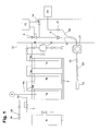
- the carbon dioxide and the disinfectant supply for such a system are shown in figure 1.
- Liquid carbon dioxide is stored in three high pressure uninsulated storage vessels 1a, 1b, 1 c. Typically about 1500 kg of liquid carbon dioxide is stored in storage vessels 1 a, 1 b, 1 c.
- the storage vessels 1 a, 1 b, 1 c are mounted on a scale 2 which is used to determine the amount of carbon dioxide stored in the storage vessels 1a, 1b, 1c.
- the storage vessels 1 a, 1b, 1 c are provided with liquid level indicators 3.
- the liquid indicators 3 and/or the scale 2 are used to stop the filling procedure when a predetermined liquid level respectively predetermined weight has been reached.
- Storage vessel 1 a is provided with tubes 4a, 4b connected to the gas phase of the stored carbon dioxide. Tubes 5a, 5b, 5c are extending into the liquid phase of each storage vessel 1 a, 1 b, 1 c. The liquid phases of storage vessels 1 a, 1 b, 1 c are connected in series, i. e. liquid tube 5a connects the liquid phases in storage vessels 1a and 1b, and liquid tube 5b the liquid phases in storage vessels 1b and 1c.
- Tube 4a connected to the gas phase of storage vessel 1a is further connected to a gas cylinder 6 filled with gaseous nitrogen at a pressure of about 200 bars.
- Tube 4a is provided with a pressure regulated valve 7 having a set pressure of about 5 to 10 bars above the boiling point of the liquid carbon dioxide in the storage vessels 1a, 1b, 1c.
- Liquid tube 5c extending into the liquid phase of storage vessel 1c is at its other end provided with an outlet valve 8 and a connection point 9 which is used for connecting a liquid carbon dioxide hose 10.
- Liquid carbon dioxide hose 10 is arranged in a hose cassette 11 and at its end provided with an ejector 12.
- Gas tube 4a leads to a gas line 13 which is connected to the liquid tube 5c downstream outlet valve 8.
- the gas flow through gas line 13 can be regulated by means of gas valve 14.
- Gas valve 14 as well as outlet valve 8 can be controlled by an operating system 15.
- Valve 14 is used to pressurize the carbon dioxide line and the liquid carbon dioxide hose 10 in order to avoid dry-ice formation in the line.
- a fill line 16 comprising a fill pump 17 is connected to liquid tube 5c.
- liquid gas supply system and liquid supply line could be arranged in other versions that depart from these specific details.
- a liquid disinfectant is supplied for example from a tank 20, and if necessary a pump, not shown in figure 1, is used to increase the feed pressure.
- a disinfectant hose 22 is connected to the disinfectant supply system. Disinfectant hose 22 and carbon dioxide hose 10 are bound together. Disinfectant hose 22 also leads to the ejector 12 which in the following will be described with reference to figure 2.
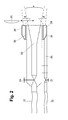
- FIG 2 the carbon dioxide and disinfectant ejector 12 is shown in greater detail.
- Liquid carbon dioxide hose 10 is connected to a nozzle 23.
- the liquid carbon dioxide flow to nozzle 23 can be manually regulated by valve 24.
- Nozzle 23, for example a Laval nozzle, is designed to achieve a gas stream of high velocity, especially to increase the gas velocity above sonic speed.
- Disinfectant hose 22 is connected via tube 25 to a disinfectant distributor 26.
- the disinfectant flow can also be regulated by using disinfectant valve 27.
- the disinfectant is transferred through tube 25 to the disinfectant distributor 26 which surrounds nozzle 23 and which has several outlet openings 28. Insulation 29 is provided between the nozzle 23 and the disinfectant distributor 26 to avoid freezing of the disinfectant.
- a spray distributor 30 is movably arranged in front of the outlet of the nozzle 23. If necessary the spray distributor 30 can be moved directly in front of nozzle 23 and thus deflect the carbon dioxide gas jet in order to create a broad gas stream.
- FIG. 1 The system shown in figures 1 and 2 is mounted on a truck. Vessels 1a, 1b, 1c are filled with liquid carbon dioxide. Therefore, a source of liquid carbon dioxide is connected to the fill line 16.
- Fill pump 17 is started and liquid carbon dioxide is pumped through liquid tubes 5c, 5b, 5a into storage vessels 1 a, 1 b, 1 c.
- the filling procedure is stopped when scale 2 or liquid level indicator 3 show a predetermined weight or predetermined liquid level indicating that storage vessels 1a, 1b, 1c are completely filled.
- filling regulator 19 opens and gaseous carbon dioxide is blown via venting line 18 to the atmosphere.
- hoses 10, 22 For distributing the disinfectant carbon dioxide hose 10 and disinfectant hose 22 are connected to the respective connection points 9 and 21 on the truck and hose cassette 11 is wheeled away in the direction to the area which shall be disinfected. When being close enough to the area to be disinfected, ejector 12 is connected to hoses 10, 22.
- Operating system 15 opens valve 14 to allow gaseous carbon dioxide to flow into carbon dioxide hose 10 in order to pressurise the hose 10. Then valve 14 is closed and the liquid carbon dioxide valve 8 is opened. Nitrogen gas is fed from nitrogen cylinder 6 into the storage vessels 1a, 1b, 1c at a pressure of about 5 bars above the boiling point of liquid carbon dioxide. Pressure regulator 7 ensures that during emptying the storage vessels 1 a, 1 b, 1 c the gas pressure is kept stable.
- the gaseous nitrogen pushes liquid carbon dioxide out of storage vessels 1 a, 1b, 1 c via liquid tube 5c and hose 10 to the carbon dioxide ejector 12. Due to the serial connection of storage vessels 1 a, 1 b, 1 c and due to the fact that gaseous nitrogen enters the storage vessels at one end and the liquid carbon dioxide is withdrawn at the opposite end, the amount of nitrogen fed into liquid tube 5c and hose 10 is minimized.
- Disinfectant is supplied from tank 20 via disinfectant hose 22 to the ejector 12, either by use of a high pressure pump not shown in figure 1 or any other suitable means.
- valve 24 is opened and liquid carbon dioxide flows into nozzle 23.
- the liquid carbon dioxide expands in nozzle 23, forms a mixture of gaseous, liquid and solid carbon dioxide and leaves the nozzle 23 with very high speed.
- Disinfectant valve 27 is opened and disinfectant flows into disinfectant distributor 26 which is coaxially arranged with nozzle 23.
- the disinfectant is pushed out through outlet openings 28, thus creating disinfectant jets surrounding the central high speed carbon dioxide jet.
- the disinfectant jets and the carbon dioxide leave ejector 12 as essentially parallel gas streams.
- the disinfectant is sprayed into the carbon dioxide jet and by the large speed of the carbon dioxide the disinfectant is divided into fine droplets forming a high speed carbon dioxide-disinfectant-mist which has a long throwing length.
Landscapes
- Health & Medical Sciences (AREA)
- Animal Behavior & Ethology (AREA)
- Epidemiology (AREA)
- Life Sciences & Earth Sciences (AREA)
- General Health & Medical Sciences (AREA)
- Public Health (AREA)
- Veterinary Medicine (AREA)
- General Chemical & Material Sciences (AREA)
- Chemical Kinetics & Catalysis (AREA)
- Chemical & Material Sciences (AREA)
- Engineering & Computer Science (AREA)
- Mechanical Engineering (AREA)
- Apparatus For Disinfection Or Sterilisation (AREA)
Abstract
The invention relates to a method to distribute a disinfectant, wherein an inert gas stream is formed by expansion of a liquid gas and said disinfectant is added to said inert gas stream after said expansion of said liquid gas.
Description
- The invention relates to a method to distribute a disinfectant.
- It is an object of the present invention to provide a method to be able to disinfect large areas within a short period of time. The amount of disinfectant should be reduced as far as possible.
- This object is achieved by a method to distribute a disinfectant, wherein an inert gas stream is formed by expansion of a liquid gas and wherein said disinfectant is added to said inert gas stream after said expansion of said liquid gas.
- The basic idea is to produce a high velocity gas jet, adding the disinfection liquid to the gas jet and spreading it as an aerosol. Therefore, according to the invention a gas is expanded in a nozzle to produce a high velocity gas stream followed by the introduction of the disinfectant into that gas stream. The high speed of the gas stream causes the liquid disinfectant to be divided into small droplets forming a high velocity mist. Due to the small size of the disinfectant droplets, they will follow the highly turbulent inert gas stream around distant corners of the area to be disinfected.
- Preferably a gas in the liquid phase is supplied to the nozzle in order to maximize the gas flow. A benefit of the inventive mixing in front of the nozzle is that the gas flow and the disinfectant flow can be varied and turned off independently of each other. Thereby, the inert gas-disinfectant-ratio can be changed easily.
- Since the disinfectant is carried by the gas stream it can permeate and expand into all or most of the space or volume to be disinfected and thus provide a total flooding capability.
- It is advantageous to form the gas stream by the expansion of liquid nitrogen or liquid carbon dioxide. High pressure gas, in particular high pressure gaseous nitrogen or high pressure gaseous carbon dioxide, can also be used. However, when the gas is not stored at the desired high pressure a compressor would be necessary and the whole system would be less mobile than a disinfection system using a liquid or liquefied gas. In principle high pressure air may also be utilized as propelling medium for the disinfectant.
- In particular the use of liquid carbon dioxide is preferred. Liquid carbon dioxide has the advantage that it can be easily stored in high pressure cylinders or tanks. And compared to other gases as liquid nitrogen or liquid argon it is quite easy to keep the liquid carbon dioxide more or less sub cooled in the whole liquid gas supply line between the liquid gas supply and the expansion nozzle, which is necessary in order to get a high flow of gas into the expansion nozzle.
- It is advantageous to form a high velocity gas stream, in particular to form a gas stream having supersonic speed. This is preferably achieved by introducing a liquid gas into a nozzle designed to increase the gas velocity when the gas is expanding in the outlet of the nozzle. In particular, the use of a conical nozzle or a Laval nozzle is preferred.
- Often it is necessary not to throw the disinfectant over large distances but to spread out the disinfectant, for example to disinfect a volume like a room or a car. This could be achieved by a spray distributor placed in front of the nozzle outlet. The distributor may be permanently fixed to the nozzle or better be a movable part of the nozzle which could be moved in front of the nozzle when needed. The distributor may be arranged to deflect the gas stream only or to deflect the combined gas and disinfectant stream.
- The nozzle can be further improved in several ways: The nozzle can be provided with valves, for example manual valves, for the gas as well as for the disinfectant stream or with handles to carry the nozzle and to support the personnel during use. Larger nozzles could be used together with some dedicated mechanical equipment as for example a steering-arm operated from a control box.
- For the supply of the liquid inert gas a gas cylinder carried as a backpack is preferably used. Such a supply system is highly mobile and can be moved around easily.
- When using a liquid gas supply it is preferred to control the pressure of the liquid gas during its feed to the nozzle in order to maximize the flow rate through the liquid gas supply line. For example a non-condensed gas is used to keep the pressure in the liquid gas supply system stable and also to sub cool more or less all the way from the liquid gas supply to the nozzle. When using liquid carbon dioxide as the propelling medium it is advantageous to pressurize the liquid carbon dioxide storage vessel with gaseous nitrogen.
- Since nitrogen is to some extent soluble in carbon dioxide which might lead to a two-phase-flow in the liquid gas supply line, it is preferred to connect at least two carbon dioxide storage vessels in series and to enter the gaseous nitrogen at one end of the combined storage vessels and to take out the liquid carbon dioxide at the opposite end. Thus the carbon dioxide will be pressurized and sub cooled during most of the emptying process of the storage vessels and less nitrogen is dissolved in the carbon dioxide.
- In a preferred embodiment of the invention the liquid gas is stored in high pressure storage vessels. The pressure in these vessels can be as high as 190 bars. Normally such high pressure vessels are not provided with any insulation. A single storage vessel will improve the total weight of the gas supply system, but one drawback is the above described risk that nitrogen used for sub cooling will be dissolved in the liquid gas. In practice it depends on the situation whether it is better to use a single storage vessel or a bundle of for example gas cylinders.
- Instead of using nitrogen to pressurize the liquid carbon dioxide it is also possible to sub cool the liquid carbon dioxide by helium. If using a single storage vessel it is also possible to use a pump to feed the liquid gas from the storage vessel to the nozzle. The pump could be used for un-insulated tanks but also for insulated tanks in which the liquid carbon dioxide is stored at a lower temperature. The pump should give such a high pressure that during the way through the liquid gas supply line as little as possible of the gas is vaporized. Otherwise a two-phase-flow will occur and the mass flow in the liquid gas supply line will be decreased. Of course such a large storage vessel could also be used with two or more liquid gas supply lines.
- The invention has several advantages compared to the prior art methods, especially when large quantities of disinfectant are to be distributed. The inventive method and system can be used at short and long distances, even if it is not possible to come close to the area which shall be disinfected. The inventive method can for example be used to disinfect cars or for nuclear decontamination.
- The inventive method to spray a mixture of small droplets of a liquid disinfectant and a high velocity gas stream is very efficient. The time for disinfecting a particular area is essentially reduced. By distributing the disinfectant as an aerosol the amount of disinfectant needed to disinfect an area or an object is also reduced.
- Another benefit of the invention is the possibility to switch between different disinfection agents. Further the amount of disinfectant mixed into the gas stream can easily be changed.
- The invention as well as further details and preferred embodiments of the invention are disclosed in the following description and illustrated in the accompanying drawings, in which
- figure 1 schematically shows a disinfecting system according to the invention, and
- figure 2 an inventive nozzle.
- The invention is preferably carried out using carbon dioxide as gas. The carbon dioxide and the disinfectant supply for such a system are shown in figure 1.
- Liquid carbon dioxide is stored in three high pressure
uninsulated storage vessels storage vessels storage vessels storage vessels storage vessels liquid level indicators 3. When filling or re-filling thestorage vessels liquid indicators 3 and/or the scale 2 are used to stop the filling procedure when a predetermined liquid level respectively predetermined weight has been reached. -
Storage vessel 1 a is provided withtubes Tubes storage vessel storage vessels liquid tube 5a connects the liquid phases instorage vessels liquid tube 5b the liquid phases instorage vessels -
Tube 4a connected to the gas phase ofstorage vessel 1a is further connected to agas cylinder 6 filled with gaseous nitrogen at a pressure of about 200 bars.Tube 4a is provided with a pressure regulated valve 7 having a set pressure of about 5 to 10 bars above the boiling point of the liquid carbon dioxide in thestorage vessels - Instead of the serial connection of
storage vessels liquid tube 5c may be used to increase the pressure of the liquid carbon dioxide and to pump the liquid carbon dioxide from thestorage vessel nozzle 12. It will be apparent to one skilled in the art that then the piping has to be changed somewhat. -
Liquid tube 5c extending into the liquid phase ofstorage vessel 1c is at its other end provided with an outlet valve 8 and aconnection point 9 which is used for connecting a liquidcarbon dioxide hose 10. Liquidcarbon dioxide hose 10 is arranged in ahose cassette 11 and at its end provided with anejector 12. -
Gas tube 4a leads to agas line 13 which is connected to theliquid tube 5c downstream outlet valve 8. The gas flow throughgas line 13 can be regulated by means ofgas valve 14.Gas valve 14 as well as outlet valve 8 can be controlled by anoperating system 15.Valve 14 is used to pressurize the carbon dioxide line and the liquidcarbon dioxide hose 10 in order to avoid dry-ice formation in the line. - To refill the liquid carbon
dioxide storage vessels line 16 comprising a fill pump 17 is connected toliquid tube 5c. To avoid over-pressure during the filling of thestorage vessels c a venting line 18, which is provided with a fillingregulator 19, branches from thegas tube 4a. - However, it will be apparent to one skilled in the art that the liquid gas supply system and liquid supply line could be arranged in other versions that depart from these specific details.
- A liquid disinfectant is supplied for example from a
tank 20, and if necessary a pump, not shown in figure 1, is used to increase the feed pressure. At connection point 21 adisinfectant hose 22 is connected to the disinfectant supply system.Disinfectant hose 22 andcarbon dioxide hose 10 are bound together.Disinfectant hose 22 also leads to theejector 12 which in the following will be described with reference to figure 2. - In figure 2 the carbon dioxide and
disinfectant ejector 12 is shown in greater detail. Liquidcarbon dioxide hose 10 is connected to anozzle 23. The liquid carbon dioxide flow tonozzle 23 can be manually regulated byvalve 24.Nozzle 23, for example a Laval nozzle, is designed to achieve a gas stream of high velocity, especially to increase the gas velocity above sonic speed. -
Disinfectant hose 22 is connected viatube 25 to adisinfectant distributor 26. The disinfectant flow can also be regulated by using disinfectant valve 27. The disinfectant is transferred throughtube 25 to thedisinfectant distributor 26 which surroundsnozzle 23 and which hasseveral outlet openings 28.Insulation 29 is provided between thenozzle 23 and thedisinfectant distributor 26 to avoid freezing of the disinfectant. - A
spray distributor 30 is movably arranged in front of the outlet of thenozzle 23. If necessary thespray distributor 30 can be moved directly in front ofnozzle 23 and thus deflect the carbon dioxide gas jet in order to create a broad gas stream. - In the following a preferred mode of operation of the invention is described. The system shown in figures 1 and 2 is mounted on a truck.
Vessels fill line 16. Fill pump 17 is started and liquid carbon dioxide is pumped throughliquid tubes storage vessels liquid level indicator 3 show a predetermined weight or predetermined liquid level indicating thatstorage vessels storage vessels regulator 19, fillingregulator 19 opens and gaseous carbon dioxide is blown via ventingline 18 to the atmosphere. - For distributing the disinfectant
carbon dioxide hose 10 anddisinfectant hose 22 are connected to therespective connection points hose cassette 11 is wheeled away in the direction to the area which shall be disinfected. When being close enough to the area to be disinfected,ejector 12 is connected tohoses -
Operating system 15 opensvalve 14 to allow gaseous carbon dioxide to flow intocarbon dioxide hose 10 in order to pressurise thehose 10. Thenvalve 14 is closed and the liquid carbon dioxide valve 8 is opened. Nitrogen gas is fed fromnitrogen cylinder 6 into thestorage vessels storage vessels - The gaseous nitrogen pushes liquid carbon dioxide out of
storage vessels liquid tube 5c andhose 10 to thecarbon dioxide ejector 12. Due to the serial connection ofstorage vessels liquid tube 5c andhose 10 is minimized. - Disinfectant is supplied from
tank 20 viadisinfectant hose 22 to theejector 12, either by use of a high pressure pump not shown in figure 1 or any other suitable means. - At the
ejector 12valve 24 is opened and liquid carbon dioxide flows intonozzle 23. The liquid carbon dioxide expands innozzle 23, forms a mixture of gaseous, liquid and solid carbon dioxide and leaves thenozzle 23 with very high speed. - Disinfectant valve 27 is opened and disinfectant flows into
disinfectant distributor 26 which is coaxially arranged withnozzle 23. The disinfectant is pushed out throughoutlet openings 28, thus creating disinfectant jets surrounding the central high speed carbon dioxide jet. The disinfectant jets and the carbon dioxide leaveejector 12 as essentially parallel gas streams. However, for certain applications it might be advantageous to adjust the ejection angle of the disinfectant and/or the carbon dioxide jet as well as their respective angles α, β of jet spread. - The disinfectant is sprayed into the carbon dioxide jet and by the large speed of the carbon dioxide the disinfectant is divided into fine droplets forming a high speed carbon dioxide-disinfectant-mist which has a long throwing length.
Claims (6)
- Method to distribute a disinfectant, characterized in that an inert gas stream is formed by expansion of a liquid gas and that said disinfectant is added to said inert gas stream after said expansion of said liquid gas.
- Method according to claim 1, characterized in that said disinfectant is substantially liquid at ambient temperature and pressure.
- Method according to any of claims 1 or 2, characterized in that said inert gas stream is formed by expansion of liquid carbon dioxide.
- Method according to any of claims 1 to 3, characterized in that an inert gas stream is formed having supersonic speed.
- Method according to any of claims 1 to 4, characterized in that prior to its expansion said liquid gas is pressurized to a pressure above the boiling point of said liquid gas.
- Method according to any of claims 1 to 5, characterized in that said liquid gas is pressurized with gaseous nitrogen or gaseous helium.
Priority Applications (1)
| Application Number | Priority Date | Filing Date | Title |
|---|---|---|---|
| EP06021438A EP1911465A1 (en) | 2006-10-12 | 2006-10-12 | Method for distributing a disinfectant |
Applications Claiming Priority (1)
| Application Number | Priority Date | Filing Date | Title |
|---|---|---|---|
| EP06021438A EP1911465A1 (en) | 2006-10-12 | 2006-10-12 | Method for distributing a disinfectant |
Publications (1)
| Publication Number | Publication Date |
|---|---|
| EP1911465A1 true EP1911465A1 (en) | 2008-04-16 |
Family
ID=37843150
Family Applications (1)
| Application Number | Title | Priority Date | Filing Date |
|---|---|---|---|
| EP06021438A Withdrawn EP1911465A1 (en) | 2006-10-12 | 2006-10-12 | Method for distributing a disinfectant |
Country Status (1)
| Country | Link |
|---|---|
| EP (1) | EP1911465A1 (en) |
Cited By (2)
| Publication number | Priority date | Publication date | Assignee | Title |
|---|---|---|---|---|
| US8454360B2 (en) | 2008-11-17 | 2013-06-04 | Koninkliijke Philips Electronics N.V. | Liquid droplet interproximal cleaning apparatus with gas stream protection |
| WO2021190708A1 (en) * | 2020-03-27 | 2021-09-30 | Mycon Gmbh | Method for water-free or greatly water-reduced cleaning, and jet device therefor |
Citations (5)
| Publication number | Priority date | Publication date | Assignee | Title |
|---|---|---|---|---|
| US1875821A (en) * | 1930-09-12 | 1932-09-06 | Aromel Corp | Atomizer |
| US3189405A (en) * | 1962-03-06 | 1965-06-15 | Robert A Fulton | Decontaminating device and fog generator |
| EP0613617A1 (en) * | 1993-03-05 | 1994-09-07 | The BOC Group plc | Atmosphere treatment apparatus |
| US6076748A (en) * | 1998-05-04 | 2000-06-20 | Resch; Darrel R. | Odor control atomizer utilizing ozone and water |
| WO2003008001A1 (en) * | 2001-07-20 | 2003-01-30 | Pure As Air Australia Pty Ltd | Apparatus and method for delivering a treatment fluid |
-
2006
- 2006-10-12 EP EP06021438A patent/EP1911465A1/en not_active Withdrawn
Patent Citations (5)
| Publication number | Priority date | Publication date | Assignee | Title |
|---|---|---|---|---|
| US1875821A (en) * | 1930-09-12 | 1932-09-06 | Aromel Corp | Atomizer |
| US3189405A (en) * | 1962-03-06 | 1965-06-15 | Robert A Fulton | Decontaminating device and fog generator |
| EP0613617A1 (en) * | 1993-03-05 | 1994-09-07 | The BOC Group plc | Atmosphere treatment apparatus |
| US6076748A (en) * | 1998-05-04 | 2000-06-20 | Resch; Darrel R. | Odor control atomizer utilizing ozone and water |
| WO2003008001A1 (en) * | 2001-07-20 | 2003-01-30 | Pure As Air Australia Pty Ltd | Apparatus and method for delivering a treatment fluid |
Cited By (2)
| Publication number | Priority date | Publication date | Assignee | Title |
|---|---|---|---|---|
| US8454360B2 (en) | 2008-11-17 | 2013-06-04 | Koninkliijke Philips Electronics N.V. | Liquid droplet interproximal cleaning apparatus with gas stream protection |
| WO2021190708A1 (en) * | 2020-03-27 | 2021-09-30 | Mycon Gmbh | Method for water-free or greatly water-reduced cleaning, and jet device therefor |
Similar Documents
| Publication | Publication Date | Title |
|---|---|---|
| US8360339B2 (en) | Fire suppression apparatus and method for generating foam | |
| AU2018226928B2 (en) | Foam production method, fire extinguishing method, and foam extinguishing appliance | |
| US6688402B1 (en) | Aerial firefighting system | |
| EP2466186A1 (en) | A process for filling a gas storage container | |
| JPH06190721A (en) | Shot blasting equipment with solid carbon dioxide pellets | |
| AU726898B2 (en) | Method and device for sequentially spraying a cryogenic liquid, cooling method and installation making application thereof | |
| AU671541B2 (en) | Cryogenic storage and delivery method and apparatus | |
| US20140158250A1 (en) | Process for filling gas storage container | |
| JP2023129467A (en) | Apparatus and method for dispensing and foaming product material | |
| JPH06511160A (en) | Methods and devices for fire fighting | |
| CN101262910A (en) | Equipment used in rescue services to form openings by cutting in roofs etc. | |
| US20100212920A1 (en) | Inert gas flooding fire suppression with water augmentation | |
| CA2328972A1 (en) | Method and high-capacity apparatus for producing fire fighting foam and foam expanding spreading device | |
| EP1454658B1 (en) | Method and system for fire suppressing | |
| KR20100069338A (en) | Dry powder fire fighting apparatus of ship with nitrogen recharger | |
| US20190368789A1 (en) | Pulsed liquid cryogen flow generator | |
| JP2009065996A (en) | Fire extinguishing system | |
| US8109341B1 (en) | Method and high-capacity apparatus for producing fire fighting foam and foam expanding spreading device | |
| CZ288387B6 (en) | Supply of high-pressure gas | |
| EP2658614B1 (en) | Method of operating a fire suppression system with dual use of gas source | |
| US20240285988A1 (en) | Compressed Gas Fire Extinguisher Apparatus and Methods | |
| JP7558883B2 (en) | Liquefied gas supply device and supply method, spray freezing device and spray freezing method | |
| NO339027B1 (en) | System and method for conditioning pressure in an LNG tank | |
| EP3600574B1 (en) | Pressure-regulated high pressure storage of halocarbon fire extinguishing agent | |
| RU2158154C1 (en) | Powder extinguisher fire engine |
Legal Events
| Date | Code | Title | Description |
|---|---|---|---|
| PUAI | Public reference made under article 153(3) epc to a published international application that has entered the european phase |
Free format text: ORIGINAL CODE: 0009012 |
|
| AK | Designated contracting states |
Kind code of ref document: A1 Designated state(s): AT BE BG CH CY CZ DE DK EE ES FI FR GB GR HU IE IS IT LI LT LU LV MC NL PL PT RO SE SI SK TR |
|
| AX | Request for extension of the european patent |
Extension state: AL BA HR MK RS |
|
| AKX | Designation fees paid | ||
| REG | Reference to a national code |
Ref country code: DE Ref legal event code: 8566 |
|
| STAA | Information on the status of an ep patent application or granted ep patent |
Free format text: STATUS: THE APPLICATION IS DEEMED TO BE WITHDRAWN |
|
| 18D | Application deemed to be withdrawn |
Effective date: 20081017 |