EP1911392A2 - Apparatus for cleaning a distal scope end of a medical viewing scope - Google Patents
Apparatus for cleaning a distal scope end of a medical viewing scope Download PDFInfo
- Publication number
- EP1911392A2 EP1911392A2 EP07253898A EP07253898A EP1911392A2 EP 1911392 A2 EP1911392 A2 EP 1911392A2 EP 07253898 A EP07253898 A EP 07253898A EP 07253898 A EP07253898 A EP 07253898A EP 1911392 A2 EP1911392 A2 EP 1911392A2
- Authority
- EP
- European Patent Office
- Prior art keywords
- distal
- sheath
- scope
- lumen
- proximal
- Prior art date
- Legal status (The legal status is an assumption and is not a legal conclusion. Google has not performed a legal analysis and makes no representation as to the accuracy of the status listed.)
- Withdrawn
Links
- 238000004140 cleaning Methods 0.000 title claims abstract description 33
- 239000012530 fluid Substances 0.000 claims abstract description 72
- 238000004891 communication Methods 0.000 claims abstract description 24
- 230000002262 irrigation Effects 0.000 claims abstract description 17
- 238000003973 irrigation Methods 0.000 claims abstract description 17
- 239000000463 material Substances 0.000 claims description 8
- 230000014509 gene expression Effects 0.000 description 46
- 238000012986 modification Methods 0.000 description 8
- 230000004048 modification Effects 0.000 description 8
- 238000000034 method Methods 0.000 description 5
- 210000001124 body fluid Anatomy 0.000 description 3
- 239000006185 dispersion Substances 0.000 description 3
- 238000007667 floating Methods 0.000 description 3
- 239000007788 liquid Substances 0.000 description 3
- 210000001015 abdomen Anatomy 0.000 description 2
- 238000010276 construction Methods 0.000 description 2
- 239000003795 chemical substances by application Substances 0.000 description 1
- 230000006835 compression Effects 0.000 description 1
- 238000007906 compression Methods 0.000 description 1
- 230000005494 condensation Effects 0.000 description 1
- 238000009833 condensation Methods 0.000 description 1
- 230000000593 degrading effect Effects 0.000 description 1
- 230000001934 delay Effects 0.000 description 1
- 238000010586 diagram Methods 0.000 description 1
- 238000007789 sealing Methods 0.000 description 1
- 238000006467 substitution reaction Methods 0.000 description 1
- 239000004094 surface-active agent Substances 0.000 description 1
Images




Classifications
-
- A—HUMAN NECESSITIES
- A61—MEDICAL OR VETERINARY SCIENCE; HYGIENE
- A61B—DIAGNOSIS; SURGERY; IDENTIFICATION
- A61B1/00—Instruments for performing medical examinations of the interior of cavities or tubes of the body by visual or photographical inspection, e.g. endoscopes; Illuminating arrangements therefor
- A61B1/00131—Accessories for endoscopes
- A61B1/00135—Oversleeves mounted on the endoscope prior to insertion
-
- A—HUMAN NECESSITIES
- A61—MEDICAL OR VETERINARY SCIENCE; HYGIENE
- A61B—DIAGNOSIS; SURGERY; IDENTIFICATION
- A61B1/00—Instruments for performing medical examinations of the interior of cavities or tubes of the body by visual or photographical inspection, e.g. endoscopes; Illuminating arrangements therefor
- A61B1/12—Instruments for performing medical examinations of the interior of cavities or tubes of the body by visual or photographical inspection, e.g. endoscopes; Illuminating arrangements therefor with cooling or rinsing arrangements
- A61B1/126—Instruments for performing medical examinations of the interior of cavities or tubes of the body by visual or photographical inspection, e.g. endoscopes; Illuminating arrangements therefor with cooling or rinsing arrangements provided with means for cleaning in-use
-
- A—HUMAN NECESSITIES
- A61—MEDICAL OR VETERINARY SCIENCE; HYGIENE
- A61B—DIAGNOSIS; SURGERY; IDENTIFICATION
- A61B1/00—Instruments for performing medical examinations of the interior of cavities or tubes of the body by visual or photographical inspection, e.g. endoscopes; Illuminating arrangements therefor
- A61B1/313—Instruments for performing medical examinations of the interior of cavities or tubes of the body by visual or photographical inspection, e.g. endoscopes; Illuminating arrangements therefor for introducing through surgical openings, e.g. laparoscopes
- A61B1/3132—Instruments for performing medical examinations of the interior of cavities or tubes of the body by visual or photographical inspection, e.g. endoscopes; Illuminating arrangements therefor for introducing through surgical openings, e.g. laparoscopes for laparoscopy
-
- A—HUMAN NECESSITIES
- A61—MEDICAL OR VETERINARY SCIENCE; HYGIENE
- A61B—DIAGNOSIS; SURGERY; IDENTIFICATION
- A61B1/00—Instruments for performing medical examinations of the interior of cavities or tubes of the body by visual or photographical inspection, e.g. endoscopes; Illuminating arrangements therefor
- A61B1/12—Instruments for performing medical examinations of the interior of cavities or tubes of the body by visual or photographical inspection, e.g. endoscopes; Illuminating arrangements therefor with cooling or rinsing arrangements
- A61B1/127—Instruments for performing medical examinations of the interior of cavities or tubes of the body by visual or photographical inspection, e.g. endoscopes; Illuminating arrangements therefor with cooling or rinsing arrangements with means for preventing fogging
Definitions
- the present invention is related generally to medical equipment, and more particularly to apparatus for cleaning a distal scope end of a medical viewing scope.
- first and second trocars are used to create two openings in the patient's abdomen.
- a rigid laparoscope is inserted through the first trocar to visualize patient tissue.
- a treating medical instrument is inserted through the second trocar to treat the patient tissue being visualized with the laparoscope.
- Bodily fluid dispersion and floating debris have a tendency to accumulate on the scope lens of the inserted laparoscope degrading the clarity of the view.
- the laparoscope must be withdrawn from the first trocar and the scope lens wiped to remove the accumulated material which caused the blurred viewing.
- the removal of the laparoscope is inconvenient and causes delays in the laparoscopic procedure.
- it is necessary for the physician to take additional time to maneuver the scope to reacquire the patient tissue of interest.
- a first expression of a first embodiment of the invention is for apparatus for cleaning a distal scope end of a medical viewing scope.
- the apparatus includes an annular sheath having open proximal and distal sheath end portions.
- the sheath is surroundingly attachable to the scope and is insertable into a patient.
- the sheath includes a tubular wall having inside and outside diameters and containing a lumen between the inside and outside diameters.
- the lumen has proximal and distal lumen ends.
- the proximal lumen end is fluidly connectable to at least one of an irrigation fluid source and a vacuum source.
- the distal scope end is in fluid communication with the distal lumen end of the attached sheath.
- a second expression of a first embodiment of the invention is for apparatus for cleaning a distal scope end of a medical viewing scope.
- the apparatus includes an annular sheath having open proximal and distal sheath end portions.
- the sheath is surroundingly attachable to the scope and is insertable into a patient.
- the sheath includes a tubular wall having inside and outside diameters and containing a lumen between the inside and outside diameters.
- the lumen has proximal and distal lumen ends.
- the proximal lumen end is fluidly connectable to at least one of an irrigation fluid source and a vacuum source.
- the distal scope end is in fluid communication with the distal lumen end of the attached sheath.
- the distal sheath end portion has an annular manifold which is in fluid communication with the distal lumen end and which includes at least one orifice pointing toward the distal scope end.
- a first expression of a second embodiment of the invention is for apparatus for cleaning a distal scope end of a medical viewing scope.
- the apparatus includes a motor-driven rotatable cannula having an open proximal cannula end and having a transparent and closed distal cannula end.
- the scope is insertable into the proximal cannula end with the distal scope end disposed proximate and spaced apart from the distal cannula end. Rotation of the cannula helps to expel any material that has accumulated on the distal cannula end when the cannula is inserted into a patient.
- a first expression of a third embodiment of the invention is for apparatus for cleaning a distal scope end of a medical viewing scope.
- the apparatus includes an annular sheath and a lens.
- the sheath has open proximal and distal sheath ends.
- the lens is positioned in and attached to the sheath and closes off the sheath proximate the distal sheath end.
- the lens has a distal surface.
- the scope is insertable into the proximal sheath end with the distal scope end disposed proximate the lens.
- the sheath is insertable into a patient.
- the sheath includes a tubular wall having inside and outside diameters and containing a lumen between the inside and outside diameters.
- the lumen has proximal and distal lumen ends.
- the proximal lumen end is fluidly connectable to at least one of an irrigation fluid source and a vacuum source.
- the distal surface of the lens is in fluid communication with the distal
- a first expression of a fourth embodiment of the invention is for apparatus for cleaning a distal scope end of a medical viewing scope.
- the apparatus includes an annular sheath having open proximal and distal sheath ends and a rotatably-driven transparent shield rotatably attachable to the sheath proximate the distal sheath end to seal the distal sheath end.
- the scope is insertable into the proximal sheath end with the distal scope end disposed proximate and spaced apart from the shield. Rotation of the shield helps to expel any material that has accumulated on the shield when the sheath and the attached shield are inserted into a patient.
- a first expression of a fifth embodiment of the invention is for apparatus for cleaning a distal scope end of a medical viewing scope.
- the apparatus includes a sleeve attachable to and slidable along the scope.
- the sleeve includes a distal sleeve tip.
- the distal sleeve tip of the attached sleeve is slidably extendable from and slidably retractable from the distal scope end.
- FIGURE 1 is a schematic view of a first embodiment of the invention including a handpiece, wherein a sheath is surroundingly attached to a scope and is inserted into a patient using a trocar, and wherein the sheath and the trocar are shown in cross section;
- FIGURE 2 is a view of the sheath of Figure 1;
- FIGURE 3 is a cross sectional view of the sheath of Figure 2 taken along lines 3-3 of Figure 2;
- FIGURE 4 is an explanatory diagram illustrating the operation of the handpiece of Figure 1;
- FIGURE 5 is a schematic view of a second embodiment of the invention, wherein a motor of a motor assembly drives a rotatable cannula, wherein the scope is disposed in the cannula, and wherein the cannula is shown in cross section;
- FIGURE 6 is a view of the cannula and the motor assembly of Figure 5;
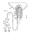
- FIGURE 7 is a schematic view of a third embodiment of the invention wherein a lens closes off an annular sheath proximate a distal sheath end, wherein a scope is inserted into the sheath, wherein the sheath is inserted into a patient using a trocar, and wherein the sheath, the lens, and the trocar are shown in cross section;
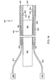
- FIGURE 8 is a view of the sheath and the lens of Figure 7;
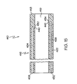
- FIGURE 9 is a cross sectional view of the sheath of Figure 8 taken along lines 9-9 of Figure 8;
- FIGURE 10 a schematic view of a fourth embodiment of the invention, wherein a rotatably-driven transparent shield is rotatably attached to a sheath proximate a distal sheath end to seal the distal sheath end, wherein a scope is inserted into a proximal sheath end, and wherein the sheath and the shield are shown in cross section;
- FIGURE 11 is a view of the sheath and the shield of Figure 10;
- FIGURE 12 is a view of the shield of Figure 11 taken along lines 12-12 of Figure 11;
- FIGURE 13 is a schematic view of a fifth embodiment of the invention wherein a slidable sleeve is attached to a scope, wherein the sleeve is shown slightly retracted from the distal scope end, and wherein the sleeve is shown in cross section;
- FIGURE 14 is a view, as in Figure 13, but showing the sleeve extended from the distal scope end;
- FIGURE 1 is a view of the sleeve of Figures 13-14.
- a first embodiment of the invention is shown in Figures 1-4.
- a first expression of the embodiment of Figures 1-4 is for apparatus 10 for cleaning a distal scope end 12 of a medical viewing scope 14.
- the apparatus 10 includes an annular sheath 16 having open proximal and distal sheath end portions 18 and 19.
- the sheath 16 is surroundingly attachable to the scope 14 and is insertable into a patient 22.
- the sheath 16 includes a tubular wall 24 having inside and outside diameters and containing a lumen 26 between the inside and outside diameters.
- the lumen 26 has proximal and distal lumen ends 28 and 30.
- the proximal lumen end 28 is fluidly connectable to at least one of an irrigation fluid source 32 and a vacuum source 34.
- a scope assembly includes the apparatus 10 and the scope 14, wherein the sheath 16 is attached to the scope 14. It is noted that "fluid” includes, without limitation, gas or gasses (e.g., air) and/or liquid or liquids.
- cleaning a distal scope end means cleaning at least a portion of the distal scope end to improve scope clarity.
- cleaning a distal scope end means cleaning at least a portion of the lens to improve lens clarity.
- the scope 14 is slidingly insertable into the proximal sheath end portion 18, the distal scope end 12 has an outside diameter, and the inside diameter of the tubular wall 24 at the distal sheath end portion 19 is less than the outside diameter of the distal scope end 12.
- the distal scope end 12 makes a press fit with the sheath 16 at the distal sheath end portion 19 as shown in Figure 1.
- the inside diameter of the tubular wall 24 has a constant taper from the proximal sheath end 18 to proximate the distal sheath end 20 of the distal sheath end portion 19.
- sheath to the scope include, without limitation, an elastomeric sheath, a compression fitting, and an elastomeric O-ring attached to the sheath proximate the distal sheath end and adapted to attachingly engage an advancing scope which has been inserted into the proximal sheath end.
- the sheath 16 is insertable into a trocar 36.
- the scope 14 is a laparoscope.
- Other types of scopes, not shown, include, without limitation, endoscopes (including gastroscopes and colonoscopes). It is noted that scopes include, without limitation, those scopes with video cameras which display an image on a monitor and those scopes having eyepieces for viewing by a physician.
- the distal sheath end portion 19 has an orifice 38 (two are shown in Figures 1 and 2 and four are shown in figure 3) which is in fluid communication with the distal lumen end 30 and which points toward the distal scope end 12.
- the distal sheath end portion 19 has a circumferentially inner surface 40 containing the orifice 38. It is noted that bodily fluid dispersion and floating debris should tend to adhere to the circumferentially inner surface 40.
- the circumferentially inner surface 40 of the distal sheath end portion 19 longitudinally extends from the distal sheath end 20 of the distal sheath end portion 19 to the distal scope end 12 of the inserted scope 14, as seen in Figure 1.
- the proximal lumen end 28 is fluidly connectable to the vacuum source 34.
- the distal sheath end portion 19 has an orifice 38 which is in fluid communication with the distal lumen end 30.
- the distal lumen end 30, for the attached sheath 16 is disposed within vacuuming distance of the distal scope end 12.
- the apparatus 10 also includes a handpiece 42 and a flexible tube 44, wherein the handpiece 42 has a fluid outlet 46, and wherein the tube 44 has proximal and distal tube ends 48 and 50, as shown in Figure 1.
- the distal tube end 50 is attachable to the sheath 16 to be in fluid communication with the proximal lumen end 28, and the proximal tube end 48 is attachable to the handpiece 42 to be in fluid communication with the fluid outlet 46.
- the handpiece 42 includes first and second fluid inlets 52 and 54, wherein the first fluid inlet 52 is fluidly connectable (such as via tubing 72) to the irrigation fluid source 32, and wherein the second fluid inlet 54 is fluidly connectable (such as via tubing 74) to the vacuum source 34.
- first fluid inlet 52 is fluidly connectable (such as via tubing 72) to the irrigation fluid source 32
- second fluid inlet 54 is fluidly connectable (such as via tubing 74) to the vacuum source 34.
- vacuum includes partial vacuum and includes aspiration.
- the term "vacuum" is relative to the pressure at the orifice 38 (or at later-discussed orifice 238 or at later-discussed second orifice 442) and that, in one example, the vacuum source may be ambient room air when the orifice 38 (or the later-discussed orifice 238 or the later-discussed second orifice 442) is exposed to a higher pressure within, for example, the insufflated abdomen of a patient.
- the handpiece 42 includes a first valve button 56 which, when pushed, fluidly connects the first fluid inlet 52 to the fluid outlet 46 and includes a second valve button 58 which, when pushed, fluidly connects the second fluid inlet 54 to the fluid outlet 46.
- a "Y" passageway 60 fluidly connects the first and second fluid inlets 52 and 54 to the fluid outlet 46.
- the first valve button 56 is operatively connected to a first valve 62 disposed in a first arm 64 of the "Y" passageway 60.
- the second valve button 56 is operatively connected to a second valve 66 disposed in a second arm 68 of the "Y" passageway 60.
- Other examples are left to the artisan.
- the distal sheath end portion 19 has a first coefficient of thermal conduction
- the distal scope end 12 has a second coefficient of thermal conduction
- the first coefficient is higher than the second coefficient to reduce fogging of the distal scope end 12.
- fogging includes condensation.
- the scope 14 has a light source (not shown) which warms the distal scope end 12, wherein the distal sheath end portion 19 acts as a heat sink for the distal scope end 12.
- a second expression of the embodiment of Figures 1-4 is for apparatus 10 for cleaning a distal scope end 12 of a medical viewing scope 14.
- the apparatus 10 includes an annular sheath 16 having open proximal and distal sheath end portions 18 and 19.
- the sheath 16 is surroundingly attachable to the scope 14 and is insertable into a patient 22.
- the sheath 16 includes a tubular wall 24 having inside and outside diameters and containing a lumen 26 between the inside and outside diameters.
- the lumen 26 has proximal and distal lumen ends 28 and 30.
- the proximal lumen end 28 is fluidly connectable to at least one of an irrigation fluid source 32 and a vacuum source 34.
- the distal scope end 12 is in fluid communication with the distal lumen end 30 of the attached sheath 16.
- the distal sheath end portion 19 has an annular manifold 70 which is in fluid communication with the distal lumen end 30 and which includes at least one orifice 38 pointing toward the distal scope end 12. It is noted that the inside diameter of the tubular wall 24 is the diameter of a bore 35 into which the scope 14 is insertable.
- a scope assembly includes the apparatus 10 and the scope 14, wherein the sheath 16 is attached to the scope 14.
- the scope 14 is a laparoscope.
- the at-least-one orifice 38 includes a plurality of circumferentially spaced apart orifices 38. It is noted that the enablements, applications, etc. of the first expression of the embodiment of Figures 1-4 are applicable to the second expression of the embodiment of Figures 1-4.
- a second embodiment of the invention is shown in Figures 5-6.
- a first expression of the embodiment of Figures 5-6 is for apparatus 110 for cleaning a distal scope end 112 of a medical viewing scope 114.
- the apparatus 110 includes a motor-driven rotatable cannula 116 having an open proximal cannula end 118 and having a transparent and closed distal cannula end 120.
- the scope 114 is insertable into the proximal cannula end 118 with the distal scope end 112 disposed proximate and spaced apart from the distal cannula end 120. Rotation of the cannula 116 helps to expel any material that has accumulated on the distal cannula end 120 when the cannula 116 is inserted into a patient.
- a scope assembly includes the apparatus 110 and the scope 114, wherein the scope 114 is inserted into the cannula 116.
- the apparatus 110 includes a motor assembly housing 122 and bearings 124.
- the motor assembly housing 122 includes a housing bore 126 having proximal and distal housing bore portions 128 and 130.
- the bearings 124 rotatably attach the cannula 116 to the motor assembly housing 122 in the distal housing bore portion 130.
- the scope 114 is inserted first into the proximal housing bore portion 128 and then into the proximal cannula end 118.
- the cannula 116 has a circumferential gear 132 which is rotated by a motor gear 134 attached to the drive shaft 136 of an electric motor 138 disposed in the motor assembly housing 122.
- the scope 114 is a laparoscope.
- a third embodiment of the invention is shown in Figures 7-9.
- a first expression of the embodiment of Figures 7-9 is for apparatus 210 for cleaning a distal scope end 212 of a medical viewing scope 214.
- the apparatus 210 includes an annular sheath 216 and a lens 217.
- the sheath 216 has open proximal and distal sheath ends 218 and 220.
- the lens 217 is disposed in and attached to the sheath 216 and closes off the sheath 216 proximate the distal sheath end 220.
- the lens 217 has a distal surface 221.
- the scope 214 is insertable into the proximal sheath end 218 with the distal scope end 212 disposed proximate the lens 217.
- the sheath 216 is insertable into a patient 222.
- the sheath 216 includes a tubular wall 224 having inside and outside diameters and containing a lumen 226 between the inside and outside diameters.
- the lumen 226 has proximal and distal lumen ends 228 and 230.
- the proximal lumen end 228 is fluidly connectable to at least one of an irrigation fluid source 232 and a vacuum source 234.
- the distal surface 221 of the lens 217 is in fluid communication with the distal lumen end 230. It is noted that the lens 217 may be a non-magnifying or a magnifying lens.
- a scope assembly includes the apparatus 210 and the scope 214, wherein the scope 214 is inserted into the sheath 216.
- the sheath 216 is insertable into a trocar 236.
- the scope 214 is a laparoscope.
- the distal sheath end portion 219 has an orifice 238 (two are shown in Figures 7 and 8 and four are shown in figure 9) which is in fluid communication with the distal lumen end 230 and which points toward the distal scope end 212.
- the distal sheath end portion 219 has a circumferentially inner surface 240 containing the orifice 238. It is noted that bodily fluid dispersion and floating debris should tend to adhere to the circumferentially inner surface 240.
- the circumferentially inner surface 240 of the distal sheath end portion 219 longitudinally extends from the distal sheath end 220 of the distal sheath end portion 219 to the distal surface 221 of the lens 217, as seen in Figures 7-8.
- the apparatus 210 also includes a handpiece 242 and a flexible tube 244, wherein the handpiece 242 has a fluid outlet 246 and the tube 244 has proximal and distal tube ends 248 and 250, as shown in Figure 7.
- the distal tube end 250 is attachable to the sheath 216 to be in fluid communication with the proximal lumen end 228, and the proximal tube end 248 is attachable to the handpiece 242 to be in fluid communication with the fluid outlet 246.
- the handpiece 242 includes first and second fluid inlets 252 and 254, wherein the first fluid inlet 252 is fluidly connectable (via tubing 260) to the irrigation fluid source 232, and wherein the second fluid inlet 254 is fluidly connectable (via tubing 262) to the vacuum source 234.
- the handpiece 242 includes a first valve button 256 which, when pushed, fluidly connects the first fluid inlet 252 to the fluid outlet 246 and includes a second valve button 258 which, when pushed, fluidly connects the second fluid inlet 254 to the fluid outlet 246.
- the distal sheath end portion 219 includes a manifold 264 fluidly connecting the distal lumen end 230 to a plurality of orifices 238 on the circumferential inner surface 240 of the distal sheath end 220, wherein the orifices 238 each point toward the distal scope end 212.
- a fourth embodiment of the invention is shown in Figures 10-12.
- a first expression of the embodiment of Figures 10-12 is for apparatus 310 for cleaning a distal scope end 312 of a medical viewing scope 314.
- the apparatus 310 includes an annular sheath 316 having open proximal and distal sheath ends 318 and 320 and a rotatably-driven transparent shield 322 rotatably attachable to the sheath 316 proximate the distal sheath end 320 to seal the distal sheath end 320.
- the scope 314 is insertable into the proximal sheath end 318 with the distal scope end 312 disposed proximate and spaced apart from the shield 322.
- Rotation of the shield 322 helps to expel any material that has accumulated on the shield 322 when the sheath 316 and the attached shield 322 are inserted into a patient.
- the sheath 316 surrounds a bore 323 into which the scope 314 is insertable and that the rotatable shield 322 seals the distal sheath end 320 by providing a rotatable sealing cover for the bore 323 proximate the distal sheath end 320.
- the shield 322 is rotatably attached to the sheath 316.
- a scope assembly includes the apparatus 310 and the scope 314, wherein the scope 314 is inserted into the sheath 316.
- the sheath 316 includes a tubular wall 324 having inside and outside diameters and containing a lumen 326 between the inside and outside diameters.
- the lumen 326 has proximal and distal lumen ends 328 and 330.
- the proximal lumen end 328 is fluidly connectable to a source of pressurized gas (not shown).
- the distal lumen end 330 points toward an aligned one of a plurality of circumferentially arrayed airfoil blades 322 which are attached to, or are a monolithic portion of, the shield 322, wherein the impact of the pressurized air on the aligned blade rotates the blade bringing an adjacent blade into alignment resulting in continuous rotation of the shield 322 as long as the pressurized gas is allowed to flow in the lumen 326.
- the gas is air.
- the proximal lumen end 328 is fluidly connectable to a source of pressurized liquid.
- Other enablements, not shown, employ electric motors or modify the sheath and the shield to be electric motor components to rotatably drive the shield, as is within the level of design skill of the artisan.
- the scope 314 is a laparoscope.
- a fifth embodiment of the invention is shown in Figures 13-15.
- a first expression of the embodiment of Figures 13-15 is for apparatus 410 for cleaning a distal scope end 412 of a medical viewing scope 414.
- the apparatus 410 includes a sleeve 416 attachable to and slidable along the scope 414.
- the sleeve 416 includes a distal sleeve tip 418.
- the distal sleeve tip 418 of the attached sleeve 416 is slidably extendable from and slidably retractable from the distal scope end 412.
- a scope assembly includes the apparatus 410 and the scope 414, wherein the sleeve 416 is attached to the scope 14.
- the sleeve 416 is a fully-annular cylindrical sleeve which, it is noted, surrounds a bore 419 into which the scope 414 is insertable.
- the sleeve is a partially-annular cylindrical sleeve.
- a physician holds a proximal portion of the scope 414 in one hand and a proximal portion of the sleeve 416 in the other hand to slide the sleeve 416 relative to the scope 414 (or equivalently to slide the scope relative to the sleeve) to retract the sleeve 416 from the distal scope end 412 (as shown in Figure 13) and to extend the sleeve 416 from the distal scope end 412 (as shown in Figure 14).
- the distal sleeve tip 418 of the extended sleeve 416 should clear blockages (such as clots) from the distal scope end 412, and the distal sleeve tip 418 of the retracted sleeve 416 should be relatively free of fluid drops.
- the sleeve 416 includes a tubular wall 422 having inside and outside diameters and containing first and second lumens 424 and 426 between the inside and outside diameters, wherein the first lumen 424 has first proximal and distal lumen ends 428 and 430, wherein the second lumen 426 has second proximal and distal lumen ends 432 and 434, wherein the first proximal lumen end 428 is fluidly connectable (such as via tubing 444) to an irrigation fluid source 436, wherein the second proximal lumen end 432 is fluidly connectable (such as via tubing 446) to a vacuum source 438, wherein the first distal lumen end 430 includes a first orifice 440 disposed at the inside diameter of the tubular wall 422, and wherein the second distal lumen end 434 includes a second orifice 442 disposed at the inside diameter of the tubular wall 422 distal the first orific
- the vacuum orifice is replaced with a pressurized gas orifice.
- the irrigation fluid and/or the pressurized gas is heated to reduce the potential for fogging.
- an anti-fogging agent such as a surfactant is added to the irrigation fluid.
- the scope 414 is a laparoscope.
Landscapes
- Health & Medical Sciences (AREA)
- Life Sciences & Earth Sciences (AREA)
- Surgery (AREA)
- Nuclear Medicine, Radiotherapy & Molecular Imaging (AREA)
- Biomedical Technology (AREA)
- Optics & Photonics (AREA)
- Pathology (AREA)
- Radiology & Medical Imaging (AREA)
- Biophysics (AREA)
- Engineering & Computer Science (AREA)
- Physics & Mathematics (AREA)
- Heart & Thoracic Surgery (AREA)
- Medical Informatics (AREA)
- Molecular Biology (AREA)
- Animal Behavior & Ethology (AREA)
- General Health & Medical Sciences (AREA)
- Public Health (AREA)
- Veterinary Medicine (AREA)
- Endoscopes (AREA)
Abstract
Description
-
- The present invention is related generally to medical equipment, and more particularly to apparatus for cleaning a distal scope end of a medical viewing scope.
- During some conventional laparoscopic procedures, first and second trocars are used to create two openings in the patient's abdomen. A rigid laparoscope is inserted through the first trocar to visualize patient tissue. A treating medical instrument is inserted through the second trocar to treat the patient tissue being visualized with the laparoscope. Bodily fluid dispersion and floating debris have a tendency to accumulate on the scope lens of the inserted laparoscope degrading the clarity of the view. Thus, at times during the laparoscopic procedure the laparoscope must be withdrawn from the first trocar and the scope lens wiped to remove the accumulated material which caused the blurred viewing. The removal of the laparoscope is inconvenient and causes delays in the laparoscopic procedure. Upon reinsertion of the laparoscope, it is necessary for the physician to take additional time to maneuver the scope to reacquire the patient tissue of interest.
- A first expression of a first embodiment of the invention is for apparatus for cleaning a distal scope end of a medical viewing scope. The apparatus includes an annular sheath having open proximal and distal sheath end portions. The sheath is surroundingly attachable to the scope and is insertable into a patient. The sheath includes a tubular wall having inside and outside diameters and containing a lumen between the inside and outside diameters. The lumen has proximal and distal lumen ends. The proximal lumen end is fluidly connectable to at least one of an irrigation fluid source and a vacuum source. The distal scope end is in fluid communication with the distal lumen end of the attached sheath.
- A second expression of a first embodiment of the invention is for apparatus for cleaning a distal scope end of a medical viewing scope. The apparatus includes an annular sheath having open proximal and distal sheath end portions. The sheath is surroundingly attachable to the scope and is insertable into a patient. The sheath includes a tubular wall having inside and outside diameters and containing a lumen between the inside and outside diameters. The lumen has proximal and distal lumen ends. The proximal lumen end is fluidly connectable to at least one of an irrigation fluid source and a vacuum source. The distal scope end is in fluid communication with the distal lumen end of the attached sheath. The distal sheath end portion has an annular manifold which is in fluid communication with the distal lumen end and which includes at least one orifice pointing toward the distal scope end.
- A first expression of a second embodiment of the invention is for apparatus for cleaning a distal scope end of a medical viewing scope. The apparatus includes a motor-driven rotatable cannula having an open proximal cannula end and having a transparent and closed distal cannula end. The scope is insertable into the proximal cannula end with the distal scope end disposed proximate and spaced apart from the distal cannula end. Rotation of the cannula helps to expel any material that has accumulated on the distal cannula end when the cannula is inserted into a patient.
- A first expression of a third embodiment of the invention is for apparatus for cleaning a distal scope end of a medical viewing scope. The apparatus includes an annular sheath and a lens. The sheath has open proximal and distal sheath ends. The lens is positioned in and attached to the sheath and closes off the sheath proximate the distal sheath end. The lens has a distal surface. The scope is insertable into the proximal sheath end with the distal scope end disposed proximate the lens. The sheath is insertable into a patient. The sheath includes a tubular wall having inside and outside diameters and containing a lumen between the inside and outside diameters. The lumen has proximal and distal lumen ends. The proximal lumen end is fluidly connectable to at least one of an irrigation fluid source and a vacuum source. The distal surface of the lens is in fluid communication with the distal lumen end.
- A first expression of a fourth embodiment of the invention is for apparatus for cleaning a distal scope end of a medical viewing scope. The apparatus includes an annular sheath having open proximal and distal sheath ends and a rotatably-driven transparent shield rotatably attachable to the sheath proximate the distal sheath end to seal the distal sheath end. The scope is insertable into the proximal sheath end with the distal scope end disposed proximate and spaced apart from the shield. Rotation of the shield helps to expel any material that has accumulated on the shield when the sheath and the attached shield are inserted into a patient.
- A first expression of a fifth embodiment of the invention is for apparatus for cleaning a distal scope end of a medical viewing scope. The apparatus includes a sleeve attachable to and slidable along the scope. The sleeve includes a distal sleeve tip. The distal sleeve tip of the attached sleeve is slidably extendable from and slidably retractable from the distal scope end.
- Several benefits and advantages are obtained from one or more of the expressions of embodiments of the invention which provide cleaning of a distal scope end of a medical viewing scope while the scope remains inserted in a patient. In one example, not removing the scope for cleaning and not reinserting the cleaned scope reduces the time for a laparoscopic procedure. In the same or a different example, not removing the scope for cleaning and not reinserting the cleaned scope keeps the inserted scope aligned with the patient tissue of interest during cleaning so that the physician does not have to take additional time to maneuver the scope to reacquire the patient tissue of interest.
- FIGURE 1 is a schematic view of a first embodiment of the invention including a handpiece, wherein a sheath is surroundingly attached to a scope and is inserted into a patient using a trocar, and wherein the sheath and the trocar are shown in cross section;
- FIGURE 2 is a view of the sheath of Figure 1;
- FIGURE 3 is a cross sectional view of the sheath of Figure 2 taken along lines 3-3 of Figure 2;
- FIGURE 4 is an explanatory diagram illustrating the operation of the handpiece of Figure 1;
- FIGURE 5 is a schematic view of a second embodiment of the invention, wherein a motor of a motor assembly drives a rotatable cannula, wherein the scope is disposed in the cannula, and wherein the cannula is shown in cross section;
- FIGURE 6 is a view of the cannula and the motor assembly of Figure 5;
- FIGURE 7 is a schematic view of a third embodiment of the invention wherein a lens closes off an annular sheath proximate a distal sheath end, wherein a scope is inserted into the sheath, wherein the sheath is inserted into a patient using a trocar, and wherein the sheath, the lens, and the trocar are shown in cross section;
- FIGURE 8 is a view of the sheath and the lens of Figure 7;
- FIGURE 9 is a cross sectional view of the sheath of Figure 8 taken along lines 9-9 of Figure 8;
- FIGURE 10 a schematic view of a fourth embodiment of the invention, wherein a rotatably-driven transparent shield is rotatably attached to a sheath proximate a distal sheath end to seal the distal sheath end, wherein a scope is inserted into a proximal sheath end, and wherein the sheath and the shield are shown in cross section;
- FIGURE 11 is a view of the sheath and the shield of Figure 10;
- FIGURE 12 is a view of the shield of Figure 11 taken along lines 12-12 of Figure 11;
- FIGURE 13 is a schematic view of a fifth embodiment of the invention wherein a slidable sleeve is attached to a scope, wherein the sleeve is shown slightly retracted from the distal scope end, and wherein the sleeve is shown in cross section;
- FIGURE 14 is a view, as in Figure 13, but showing the sleeve extended from the distal scope end; and
- FIGURE 1 is a view of the sleeve of Figures 13-14.
- Before explaining the several embodiments of the present invention in detail, it should be noted that each embodiment is not limited in its application or use to the details of construction and arrangement of parts and steps illustrated in the accompanying drawings and description. The illustrative embodiments of the invention may be implemented or incorporated in other embodiments, variations and modifications, and may be practiced or carried out in various ways. Furthermore, unless otherwise indicated, the terms and expressions employed herein have been chosen for the purpose of describing the illustrative embodiments of the present invention for the convenience of the reader and are not for the purpose of limiting the invention.
- It is further understood that any one or more of the following-described expressions, embodiments, examples, etc. can be combined with any one or more of the other following-described expressions, embodiments, examples, etc.
- A first embodiment of the invention is shown in Figures 1-4. A first expression of the embodiment of Figures 1-4 is for
apparatus 10 for cleaning adistal scope end 12 of amedical viewing scope 14. Theapparatus 10 includes anannular sheath 16 having open proximal and distalsheath end portions sheath 16 is surroundingly attachable to thescope 14 and is insertable into apatient 22. Thesheath 16 includes atubular wall 24 having inside and outside diameters and containing alumen 26 between the inside and outside diameters. Thelumen 26 has proximal and distal lumen ends 28 and 30. Theproximal lumen end 28 is fluidly connectable to at least one of anirrigation fluid source 32 and avacuum source 34. Thedistal scope end 12 is in fluid communication with thedistal lumen end 30 of the attachedsheath 16. It is noted that the inside diameter of thetubular wall 24 is the diameter of abore 35 into which thescope 14 is insertable. In an alternate first expression, a scope assembly includes theapparatus 10 and thescope 14, wherein thesheath 16 is attached to thescope 14. It is noted that "fluid" includes, without limitation, gas or gasses (e.g., air) and/or liquid or liquids. - It is noted that "cleaning a distal scope end" means cleaning at least a portion of the distal scope end to improve scope clarity. In the case of a scope having a lens at the distal scope end, "cleaning a distal scope end" means cleaning at least a portion of the lens to improve lens clarity.
- In one enablement of the first expression of the embodiment of Figures 1-4, the
scope 14 is slidingly insertable into the proximalsheath end portion 18, thedistal scope end 12 has an outside diameter, and the inside diameter of thetubular wall 24 at the distalsheath end portion 19 is less than the outside diameter of thedistal scope end 12. In one variation, thedistal scope end 12 makes a press fit with thesheath 16 at the distalsheath end portion 19 as shown in Figure 1. In one modification, the inside diameter of thetubular wall 24 has a constant taper from theproximal sheath end 18 to proximate thedistal sheath end 20 of the distalsheath end portion 19. Other attachments, not shown, of the sheath to the scope include, without limitation, an elastomeric sheath, a compression fitting, and an elastomeric O-ring attached to the sheath proximate the distal sheath end and adapted to attachingly engage an advancing scope which has been inserted into the proximal sheath end. - In one application of the first expression of the embodiment of Figures 1-4, the
sheath 16 is insertable into atrocar 36. In one variation, thescope 14 is a laparoscope. Other types of scopes, not shown, include, without limitation, endoscopes (including gastroscopes and colonoscopes). It is noted that scopes include, without limitation, those scopes with video cameras which display an image on a monitor and those scopes having eyepieces for viewing by a physician. - In one implementation of the first expression of the embodiment of Figures 1-4, the distal
sheath end portion 19 has an orifice 38 (two are shown in Figures 1 and 2 and four are shown in figure 3) which is in fluid communication with thedistal lumen end 30 and which points toward thedistal scope end 12. In one variation, the distalsheath end portion 19 has a circumferentiallyinner surface 40 containing theorifice 38. It is noted that bodily fluid dispersion and floating debris should tend to adhere to the circumferentiallyinner surface 40. In one modification, the circumferentiallyinner surface 40 of the distalsheath end portion 19 longitudinally extends from thedistal sheath end 20 of the distalsheath end portion 19 to thedistal scope end 12 of the insertedscope 14, as seen in Figure 1. - In one arrangement of the first expression of the embodiment of Figures 1-4, the
proximal lumen end 28 is fluidly connectable to thevacuum source 34. In one variation, the distalsheath end portion 19 has anorifice 38 which is in fluid communication with thedistal lumen end 30. In one modification, thedistal lumen end 30, for the attachedsheath 16, is disposed within vacuuming distance of thedistal scope end 12. - In one extension of the first expression of the embodiment of Figures 1-4, the
apparatus 10 also includes ahandpiece 42 and aflexible tube 44, wherein thehandpiece 42 has afluid outlet 46, and wherein thetube 44 has proximal and distal tube ends 48 and 50, as shown in Figure 1. Thedistal tube end 50 is attachable to thesheath 16 to be in fluid communication with theproximal lumen end 28, and theproximal tube end 48 is attachable to thehandpiece 42 to be in fluid communication with thefluid outlet 46. In one variation, thehandpiece 42 includes first and secondfluid inlets first fluid inlet 52 is fluidly connectable (such as via tubing 72) to theirrigation fluid source 32, and wherein thesecond fluid inlet 54 is fluidly connectable (such as via tubing 74) to thevacuum source 34. It is noted that the term "vacuum" includes partial vacuum and includes aspiration. It is also noted that the term "vacuum" is relative to the pressure at the orifice 38 (or at later-discussedorifice 238 or at later-discussed second orifice 442) and that, in one example, the vacuum source may be ambient room air when the orifice 38 (or the later-discussedorifice 238 or the later-discussed second orifice 442) is exposed to a higher pressure within, for example, the insufflated abdomen of a patient. In one modification, thehandpiece 42 includes afirst valve button 56 which, when pushed, fluidly connects thefirst fluid inlet 52 to thefluid outlet 46 and includes asecond valve button 58 which, when pushed, fluidly connects thesecond fluid inlet 54 to thefluid outlet 46. - In one example, as shown in Figure 4, a "Y"
passageway 60 fluidly connects the first and secondfluid inlets fluid outlet 46. Thefirst valve button 56 is operatively connected to afirst valve 62 disposed in afirst arm 64 of the "Y"passageway 60. Thesecond valve button 56 is operatively connected to asecond valve 66 disposed in asecond arm 68 of the "Y"passageway 60. Other examples are left to the artisan. - In one construction of the first expression of the embodiment of Figures 1-4, the distal
sheath end portion 19 has a first coefficient of thermal conduction, thedistal scope end 12 has a second coefficient of thermal conduction, and the first coefficient is higher than the second coefficient to reduce fogging of thedistal scope end 12. It is noted that the term "fogging" includes condensation. In one example, thescope 14 has a light source (not shown) which warms thedistal scope end 12, wherein the distalsheath end portion 19 acts as a heat sink for thedistal scope end 12. - A second expression of the embodiment of Figures 1-4 is for
apparatus 10 for cleaning adistal scope end 12 of amedical viewing scope 14. Theapparatus 10 includes anannular sheath 16 having open proximal and distalsheath end portions sheath 16 is surroundingly attachable to thescope 14 and is insertable into apatient 22. Thesheath 16 includes atubular wall 24 having inside and outside diameters and containing alumen 26 between the inside and outside diameters. Thelumen 26 has proximal and distal lumen ends 28 and 30. Theproximal lumen end 28 is fluidly connectable to at least one of anirrigation fluid source 32 and avacuum source 34. Thedistal scope end 12 is in fluid communication with thedistal lumen end 30 of the attachedsheath 16. The distalsheath end portion 19 has anannular manifold 70 which is in fluid communication with thedistal lumen end 30 and which includes at least oneorifice 38 pointing toward thedistal scope end 12. It is noted that the inside diameter of thetubular wall 24 is the diameter of abore 35 into which thescope 14 is insertable. In an alternate second expression, a scope assembly includes theapparatus 10 and thescope 14, wherein thesheath 16 is attached to thescope 14. - In one variation of the second expression of the embodiment of Figures 1-4, the
scope 14 is a laparoscope. In one arrangement of the second expression of the embodiment of Figures 1-4, the at-least-oneorifice 38 includes a plurality of circumferentially spaced apart orifices 38. It is noted that the enablements, applications, etc. of the first expression of the embodiment of Figures 1-4 are applicable to the second expression of the embodiment of Figures 1-4. - A second embodiment of the invention is shown in Figures 5-6. A first expression of the embodiment of Figures 5-6 is for
apparatus 110 for cleaning adistal scope end 112 of amedical viewing scope 114. Theapparatus 110 includes a motor-drivenrotatable cannula 116 having an openproximal cannula end 118 and having a transparent and closeddistal cannula end 120. Thescope 114 is insertable into theproximal cannula end 118 with thedistal scope end 112 disposed proximate and spaced apart from thedistal cannula end 120. Rotation of thecannula 116 helps to expel any material that has accumulated on thedistal cannula end 120 when thecannula 116 is inserted into a patient. It is noted that thecannula 116 surrounds acannula bore 121 into which thescope 114 is insertable and that the closeddistal cannula end 120 closes the cannula bore 121. In an alternate first expression, a scope assembly includes theapparatus 110 and thescope 114, wherein thescope 114 is inserted into thecannula 116. - In one enablement of the first expression of the embodiment of Figures 5-6, the
apparatus 110 includes amotor assembly housing 122 andbearings 124. Themotor assembly housing 122 includes ahousing bore 126 having proximal and distal housing boreportions bearings 124 rotatably attach thecannula 116 to themotor assembly housing 122 in the distalhousing bore portion 130. Thescope 114 is inserted first into the proximalhousing bore portion 128 and then into theproximal cannula end 118. Thecannula 116 has acircumferential gear 132 which is rotated by amotor gear 134 attached to thedrive shaft 136 of anelectric motor 138 disposed in themotor assembly housing 122. Although not shown in the figures, in this enablement wires would extend from theelectric motor 138 to a switch on a handpiece containing a battery. Other enablements for having a motor drive therotatable cannula 116 include, for example and without limitation, having an AC or DC or non-electric motor disposed in a trocar or on a cart and are left to the artisan. In one variation of the first expression of the embodiment of Figures 5-6, thescope 114 is a laparoscope. - A third embodiment of the invention is shown in Figures 7-9. A first expression of the embodiment of Figures 7-9 is for
apparatus 210 for cleaning adistal scope end 212 of amedical viewing scope 214. Theapparatus 210 includes anannular sheath 216 and alens 217. Thesheath 216 has open proximal and distal sheath ends 218 and 220. Thelens 217 is disposed in and attached to thesheath 216 and closes off thesheath 216 proximate thedistal sheath end 220. Thelens 217 has adistal surface 221. Thescope 214 is insertable into theproximal sheath end 218 with thedistal scope end 212 disposed proximate thelens 217. Thesheath 216 is insertable into apatient 222. Thesheath 216 includes atubular wall 224 having inside and outside diameters and containing alumen 226 between the inside and outside diameters. Thelumen 226 has proximal and distal lumen ends 228 and 230. Theproximal lumen end 228 is fluidly connectable to at least one of anirrigation fluid source 232 and avacuum source 234. Thedistal surface 221 of thelens 217 is in fluid communication with thedistal lumen end 230. It is noted that thelens 217 may be a non-magnifying or a magnifying lens. It is noted that thesheath 216 surrounds abore 235 into which thescope 214 is insertable and that thelens 217 closes off thesheath 216 by closing off thebore 235. In an alternate first expression, a scope assembly includes theapparatus 210 and thescope 214, wherein thescope 214 is inserted into thesheath 216. - In one application of the first expression of the embodiment of Figures 7-9, the
sheath 216 is insertable into atrocar 236. In one variation, thescope 214 is a laparoscope. - In one implementation of the first expression of the embodiment of Figures 7-9, the distal
sheath end portion 219 has an orifice 238 (two are shown in Figures 7 and 8 and four are shown in figure 9) which is in fluid communication with thedistal lumen end 230 and which points toward thedistal scope end 212. In one variation, the distalsheath end portion 219 has a circumferentiallyinner surface 240 containing theorifice 238. It is noted that bodily fluid dispersion and floating debris should tend to adhere to the circumferentiallyinner surface 240. In one modification, the circumferentiallyinner surface 240 of the distalsheath end portion 219 longitudinally extends from thedistal sheath end 220 of the distalsheath end portion 219 to thedistal surface 221 of thelens 217, as seen in Figures 7-8. - In one extension of the first expression of the embodiment of Figures 7-9, the
apparatus 210 also includes ahandpiece 242 and aflexible tube 244, wherein thehandpiece 242 has afluid outlet 246 and thetube 244 has proximal and distal tube ends 248 and 250, as shown in Figure 7. Thedistal tube end 250 is attachable to thesheath 216 to be in fluid communication with theproximal lumen end 228, and theproximal tube end 248 is attachable to thehandpiece 242 to be in fluid communication with thefluid outlet 246. In one variation, thehandpiece 242 includes first and secondfluid inlets fluid inlet 252 is fluidly connectable (via tubing 260) to theirrigation fluid source 232, and wherein the secondfluid inlet 254 is fluidly connectable (via tubing 262) to thevacuum source 234. In one modification, thehandpiece 242 includes afirst valve button 256 which, when pushed, fluidly connects the firstfluid inlet 252 to thefluid outlet 246 and includes asecond valve button 258 which, when pushed, fluidly connects the secondfluid inlet 254 to thefluid outlet 246. In one example, the distalsheath end portion 219 includes a manifold 264 fluidly connecting thedistal lumen end 230 to a plurality oforifices 238 on the circumferentialinner surface 240 of thedistal sheath end 220, wherein theorifices 238 each point toward thedistal scope end 212. - A fourth embodiment of the invention is shown in Figures 10-12. A first expression of the embodiment of Figures 10-12 is for
apparatus 310 for cleaning adistal scope end 312 of amedical viewing scope 314. Theapparatus 310 includes anannular sheath 316 having open proximal and distal sheath ends 318 and 320 and a rotatably-driventransparent shield 322 rotatably attachable to thesheath 316 proximate thedistal sheath end 320 to seal thedistal sheath end 320. Thescope 314 is insertable into theproximal sheath end 318 with thedistal scope end 312 disposed proximate and spaced apart from theshield 322. Rotation of theshield 322 helps to expel any material that has accumulated on theshield 322 when thesheath 316 and the attachedshield 322 are inserted into a patient. It is noted that thesheath 316 surrounds abore 323 into which thescope 314 is insertable and that therotatable shield 322 seals thedistal sheath end 320 by providing a rotatable sealing cover for thebore 323 proximate thedistal sheath end 320. In one example, theshield 322 is rotatably attached to thesheath 316. In an alternate first expression, a scope assembly includes theapparatus 310 and thescope 314, wherein thescope 314 is inserted into thesheath 316. - In a first enablement of the first expression of the embodiment of Figures 10-12, the
sheath 316 includes atubular wall 324 having inside and outside diameters and containing alumen 326 between the inside and outside diameters. Thelumen 326 has proximal and distal lumen ends 328 and 330. Theproximal lumen end 328 is fluidly connectable to a source of pressurized gas (not shown). Thedistal lumen end 330 points toward an aligned one of a plurality of circumferentially arrayedairfoil blades 322 which are attached to, or are a monolithic portion of, theshield 322, wherein the impact of the pressurized air on the aligned blade rotates the blade bringing an adjacent blade into alignment resulting in continuous rotation of theshield 322 as long as the pressurized gas is allowed to flow in thelumen 326. In one variation, the gas is air. Other choices for the gas are left to the artisan. In a second enablement, theproximal lumen end 328 is fluidly connectable to a source of pressurized liquid. Other enablements, not shown, employ electric motors or modify the sheath and the shield to be electric motor components to rotatably drive the shield, as is within the level of design skill of the artisan. - In one variation of the first expression of the embodiment of Figures 10-12, the
scope 314 is a laparoscope. - A fifth embodiment of the invention is shown in Figures 13-15. A first expression of the embodiment of Figures 13-15 is for
apparatus 410 for cleaning adistal scope end 412 of amedical viewing scope 414. Theapparatus 410 includes asleeve 416 attachable to and slidable along thescope 414. Thesleeve 416 includes adistal sleeve tip 418. Thedistal sleeve tip 418 of the attachedsleeve 416 is slidably extendable from and slidably retractable from thedistal scope end 412. In an alternate first expression, a scope assembly includes theapparatus 410 and thescope 414, wherein thesleeve 416 is attached to thescope 14. - In a first enablement of the first expression of the embodiment of Figures 13-15, the
sleeve 416 is a fully-annular cylindrical sleeve which, it is noted, surrounds abore 419 into which thescope 414 is insertable. In a second enablement, the sleeve is a partially-annular cylindrical sleeve. In one employment of the first expression of the embodiment of Figures 13-15, a physician holds a proximal portion of thescope 414 in one hand and a proximal portion of thesleeve 416 in the other hand to slide thesleeve 416 relative to the scope 414 (or equivalently to slide the scope relative to the sleeve) to retract thesleeve 416 from the distal scope end 412 (as shown in Figure 13) and to extend thesleeve 416 from the distal scope end 412 (as shown in Figure 14). - In one employment of the first expression of the embodiment of Figures 13-15, the
distal sleeve tip 418 of theextended sleeve 416 should clear blockages (such as clots) from thedistal scope end 412, and thedistal sleeve tip 418 of the retractedsleeve 416 should be relatively free of fluid drops. - In a first implementation of the first expression of the embodiment of Figures 13-15, the
sleeve 416 includes atubular wall 422 having inside and outside diameters and containing first andsecond lumens first lumen 424 has first proximal and distal lumen ends 428 and 430, wherein thesecond lumen 426 has second proximal and distal lumen ends 432 and 434, wherein the firstproximal lumen end 428 is fluidly connectable (such as via tubing 444) to anirrigation fluid source 436, wherein the secondproximal lumen end 432 is fluidly connectable (such as via tubing 446) to avacuum source 438, wherein the firstdistal lumen end 430 includes afirst orifice 440 disposed at the inside diameter of thetubular wall 422, and wherein the seconddistal lumen end 434 includes asecond orifice 442 disposed at the inside diameter of thetubular wall 422 distal thefirst orifice 440, wherein thesleeve 416 is hermetically slidable along thescope 414, and wherein thesleeve 416, when extending beyond thedistal scope end 412 first exposes thesecond orifice 442 and then thefirst orifice 440. In this implementation, the separate first andsecond lumens - In a second implementation, not shown, the vacuum orifice is replaced with a pressurized gas orifice. In one variation, the irrigation fluid and/or the pressurized gas is heated to reduce the potential for fogging. In the same or a different variation, an anti-fogging agent (such as a surfactant) is added to the irrigation fluid.
- In one variation of the first expression of the embodiment of Figures 13-15, the
scope 414 is a laparoscope. - Several benefits and advantages are obtained from one or more of the expressions of embodiments of the invention which provide cleaning of a distal scope end of a medical viewing scope while the scope remains inserted in a patient. In one example, not removing the scope for cleaning and not reinserting the cleaned scope reduces the time for a laparoscopic procedure. In the same or a different example, not removing the scope for cleaning and not reinserting the cleaned scope keeps the inserted scope aligned with the patient tissue of interest during cleaning so that the physician does not have to take additional time to maneuver the scope to reacquire the patient tissue of interest.
- While the present invention has been illustrated by a description of several expressions, embodiments, and examples, etc. thereof, it is not the intention of the applicants to restrict or limit the spirit and scope of the appended claims to such detail. Numerous other variations, changes, and substitutions will occur to those skilled in the art without departing from the scope of the invention. It will be understood that the foregoing description is provided by way of example, and that other modifications may occur to those skilled in the art without departing from the scope and spirit of the appended Claims.
Claims (15)
- Apparatus for cleaning a distal scope end of a medical viewing scope, wherein the apparatus comprises an annular sheath having open proximal and distal sheath end portions, wherein the sheath is surroundingly attachable to the scope and is insertable into a patient, wherein the sheath includes a tubular wall having inside and outside diameters and containing a lumen between the inside and outside diameters, wherein the lumen has proximal and distal lumen ends, wherein the proximal lumen end is fluidly connectable to at least one of an irrigation fluid source and a vacuum source, and wherein the distal scope end is in fluid communication with the distal lumen end of the attached sheath.
- The apparatus of claim 1, wherein the scope is slidingly insertable into the proximal sheath end portion, wherein the distal scope end has an outside diameter, and wherein the inside diameter of the tubular wall at the distal sheath end portion is less than the outside diameter of the distal scope end.
- The apparatus of claim 1, wherein the sheath is insertable into a trocar.
- The apparatus of claim 3, wherein the scope is a laparoscope.
- The apparatus of claim 1, wherein the distal sheath end portion has an orifice which is in fluid communication with the distal lumen end and which points toward the distal scope end.
- The apparatus of claim 5, wherein the distal sheath end portion has a circumferentially inner surface containing the orifice.
- The apparatus of claim 1, wherein the proximal lumen end is fluidly connectable to the vacuum source, and wherein the distal sheath end portion has an orifice which is in fluid communication with the distal lumen end and which, for the attached sheath, is disposed within vacuuming distance of the distal scope end.
- The apparatus of claim 1, also including a handpiece and a flexible tube, wherein the handpiece has a fluid outlet, wherein the tube has proximal and distal tube ends, wherein the distal tube end is attachable to the sheath to be in fluid communication with the proximal lumen end, wherein the proximal tube end is attachable to the handpiece to be in fluid communication with the fluid outlet.
- The apparatus of claim 8, wherein the handpiece includes first and second fluid inlets, wherein the first fluid inlet is fluidly connectable to the irrigation fluid source, and wherein the second fluid inlet is fluidly connectable to the vacuum source.
- The apparatus of claim 9, wherein the handpiece includes a first valve button which, when pushed, fluidly connects the first fluid inlet to the fluid outlet and includes a second valve button which, when pushed, fluidly connects the second fluid inlet to the fluid outlet.
- Apparatus for cleaning a distal scope end of a medical viewing scope, wherein the apparatus comprises an annular sheath having open proximal and distal sheath end portions, wherein the sheath is surroundingly attachable to the scope and is insertable into a patient, wherein the sheath includes a tubular wall having inside and outside diameters and containing a lumen between the inside and outside diameters, wherein the lumen has proximal and distal lumen ends, wherein the proximal lumen end is fluidly connectable to at least one of an irrigation fluid source and a vacuum source, wherein the distal scope end is in fluid communication with the distal lumen end of the attached sheath, wherein the distal sheath end portion has an annular manifold which is in fluid communication with the distal lumen end and which includes at least one orifice pointing toward the distal scope end.
- Apparatus for cleaning a distal scope end of a medical viewing scope, wherein the apparatus comprises a motor-driven rotatable cannula having an open proximal cannula end and having a transparent and closed distal cannula end, wherein the scope is insertable into the proximal cannula end with the distal scope end disposed proximate and spaced apart from the distal cannula end, and wherein rotation of the cannula helps to expel any material that has accumulated on the distal cannula end when the cannula is inserted into a patient.
- Apparatus for cleaning a distal scope end of a medical viewing scope, wherein the apparatus comprises an annular sheath and a lens, wherein the sheath has open proximal and distal sheath ends, wherein the lens is disposed in and attached to the sheath and closes off the sheath proximate the distal sheath end, wherein the lens has a distal surface, wherein the scope is insertable into the proximal sheath end with the distal scope end disposed proximate the lens, wherein the sheath is insertable into a patient, wherein the sheath includes a tubular wall having inside and outside diameters and containing a lumen between the inside and outside diameters, wherein the lumen has proximal and distal lumen ends, wherein the proximal lumen end is fluidly connectable to at least one of an irrigation fluid source and a vacuum source, and wherein the distal surface of the lens is in fluid communication with the distal lumen end.
- Apparatus for cleaning a distal scope end of a medical viewing scope, wherein the apparatus comprises an annular sheath having open proximal and distal sheath ends and a rotatably-driven transparent shield rotatably attachable to the sheath proximate the distal sheath end to seal the distal sheath end, wherein the scope is insertable into the proximal sheath end with the distal scope end disposed proximate and spaced apart from the shield, and wherein rotation of the shield helps to expel any material that has accumulated on the shield when the sheath and the attached shield are inserted into a patient.
- Apparatus for cleaning a distal scope end of a medical viewing scope, wherein the apparatus comprises a sleeve attachable to and slidable along the scope, wherein the sleeve includes a distal sleeve tip, and wherein the distal sleeve tip of the attached sleeve is slidably extendable from and slidably retractable from the distal scope end.
Applications Claiming Priority (1)
| Application Number | Priority Date | Filing Date | Title |
|---|---|---|---|
| US11/542,060 US20080081948A1 (en) | 2006-10-03 | 2006-10-03 | Apparatus for cleaning a distal scope end of a medical viewing scope |
Publications (2)
| Publication Number | Publication Date |
|---|---|
| EP1911392A2 true EP1911392A2 (en) | 2008-04-16 |
| EP1911392A3 EP1911392A3 (en) | 2008-07-30 |
Family
ID=39110607
Family Applications (1)
| Application Number | Title | Priority Date | Filing Date |
|---|---|---|---|
| EP07253898A Withdrawn EP1911392A3 (en) | 2006-10-03 | 2007-10-02 | Apparatus for cleaning a distal scope end of a medical viewing scope |
Country Status (5)
| Country | Link |
|---|---|
| US (1) | US20080081948A1 (en) |
| EP (1) | EP1911392A3 (en) |
| CN (1) | CN101156768A (en) |
| AU (1) | AU2007219275A1 (en) |
| CA (1) | CA2605261A1 (en) |
Cited By (1)
| Publication number | Priority date | Publication date | Assignee | Title |
|---|---|---|---|---|
| EP2145578A1 (en) * | 2008-07-14 | 2010-01-20 | Ethicon Endo-Surgery, Inc. | Methods and devices for maintaining visibility and providing irrigation and /or suction during surgical procedures |
Families Citing this family (358)
| Publication number | Priority date | Publication date | Assignee | Title |
|---|---|---|---|---|
| EP1301118B1 (en) | 2000-07-14 | 2006-09-06 | Xillix Technologies Corp. | Compact fluorescence endoscopy video system |
| US20060241496A1 (en) | 2002-01-15 | 2006-10-26 | Xillix Technologies Corp. | Filter for use with imaging endoscopes |
| US20070084897A1 (en) | 2003-05-20 | 2007-04-19 | Shelton Frederick E Iv | Articulating surgical stapling instrument incorporating a two-piece e-beam firing mechanism |
| US9060770B2 (en) | 2003-05-20 | 2015-06-23 | Ethicon Endo-Surgery, Inc. | Robotically-driven surgical instrument with E-beam driver |
| US9072535B2 (en) | 2011-05-27 | 2015-07-07 | Ethicon Endo-Surgery, Inc. | Surgical stapling instruments with rotatable staple deployment arrangements |
| US11890012B2 (en) | 2004-07-28 | 2024-02-06 | Cilag Gmbh International | Staple cartridge comprising cartridge body and attached support |
| US11484312B2 (en) | 2005-08-31 | 2022-11-01 | Cilag Gmbh International | Staple cartridge comprising a staple driver arrangement |
| US7934630B2 (en) | 2005-08-31 | 2011-05-03 | Ethicon Endo-Surgery, Inc. | Staple cartridges for forming staples having differing formed staple heights |
| US10159482B2 (en) | 2005-08-31 | 2018-12-25 | Ethicon Llc | Fastener cartridge assembly comprising a fixed anvil and different staple heights |
| US7669746B2 (en) | 2005-08-31 | 2010-03-02 | Ethicon Endo-Surgery, Inc. | Staple cartridges for forming staples having differing formed staple heights |
| US11246590B2 (en) | 2005-08-31 | 2022-02-15 | Cilag Gmbh International | Staple cartridge including staple drivers having different unfired heights |
| US20070106317A1 (en) | 2005-11-09 | 2007-05-10 | Shelton Frederick E Iv | Hydraulically and electrically actuated articulation joints for surgical instruments |
| US11278279B2 (en) | 2006-01-31 | 2022-03-22 | Cilag Gmbh International | Surgical instrument assembly |
| US8186555B2 (en) | 2006-01-31 | 2012-05-29 | Ethicon Endo-Surgery, Inc. | Motor-driven surgical cutting and fastening instrument with mechanical closure system |
| US20120292367A1 (en) | 2006-01-31 | 2012-11-22 | Ethicon Endo-Surgery, Inc. | Robotically-controlled end effector |
| US11793518B2 (en) | 2006-01-31 | 2023-10-24 | Cilag Gmbh International | Powered surgical instruments with firing system lockout arrangements |
| US20110290856A1 (en) | 2006-01-31 | 2011-12-01 | Ethicon Endo-Surgery, Inc. | Robotically-controlled surgical instrument with force-feedback capabilities |
| US7845537B2 (en) | 2006-01-31 | 2010-12-07 | Ethicon Endo-Surgery, Inc. | Surgical instrument having recording capabilities |
| US7753904B2 (en) | 2006-01-31 | 2010-07-13 | Ethicon Endo-Surgery, Inc. | Endoscopic surgical instrument with a handle that can articulate with respect to the shaft |
| US8708213B2 (en) | 2006-01-31 | 2014-04-29 | Ethicon Endo-Surgery, Inc. | Surgical instrument having a feedback system |
| US8820603B2 (en) | 2006-01-31 | 2014-09-02 | Ethicon Endo-Surgery, Inc. | Accessing data stored in a memory of a surgical instrument |
| US20090303317A1 (en) | 2006-02-07 | 2009-12-10 | Novadaq Technologies Inc. | Near infrared imaging |
| US8992422B2 (en) | 2006-03-23 | 2015-03-31 | Ethicon Endo-Surgery, Inc. | Robotically-controlled endoscopic accessory channel |
| US7753843B2 (en) | 2006-05-09 | 2010-07-13 | Boston Scientific Scimed, Inc. | Medical device positioning system |
| US10568652B2 (en) | 2006-09-29 | 2020-02-25 | Ethicon Llc | Surgical staples having attached drivers of different heights and stapling instruments for deploying the same |
| US11980366B2 (en) | 2006-10-03 | 2024-05-14 | Cilag Gmbh International | Surgical instrument |
| US20080108871A1 (en) * | 2006-11-06 | 2008-05-08 | Mohr Catherine J | Vacuum stabilized overtube for endoscopic surgery |
| US11291441B2 (en) | 2007-01-10 | 2022-04-05 | Cilag Gmbh International | Surgical instrument with wireless communication between control unit and remote sensor |
| US8632535B2 (en) | 2007-01-10 | 2014-01-21 | Ethicon Endo-Surgery, Inc. | Interlock and surgical instrument including same |
| US8684253B2 (en) | 2007-01-10 | 2014-04-01 | Ethicon Endo-Surgery, Inc. | Surgical instrument with wireless communication between a control unit of a robotic system and remote sensor |
| US20080169332A1 (en) | 2007-01-11 | 2008-07-17 | Shelton Frederick E | Surgical stapling device with a curved cutting member |
| US8727197B2 (en) | 2007-03-15 | 2014-05-20 | Ethicon Endo-Surgery, Inc. | Staple cartridge cavity configuration with cooperative surgical staple |
| US8931682B2 (en) | 2007-06-04 | 2015-01-13 | Ethicon Endo-Surgery, Inc. | Robotically-controlled shaft based rotary drive systems for surgical instruments |
| US11857181B2 (en) | 2007-06-04 | 2024-01-02 | Cilag Gmbh International | Robotically-controlled shaft based rotary drive systems for surgical instruments |
| US10307041B2 (en) | 2007-06-08 | 2019-06-04 | Medeon Biodesign, Inc. | Lens cover modification |
| EP2157917B1 (en) * | 2007-06-08 | 2021-11-10 | Medeon Biodesign, Inc. | Devices for closure of wounds |
| US9241610B2 (en) | 2009-12-08 | 2016-01-26 | Medeon Biodesign, Inc. | Devices and methods for removal of debris from the objective lens of an endoscope |
| US9050036B2 (en) * | 2007-06-19 | 2015-06-09 | Minimally Invasive Devices, Inc. | Device for maintaining visualization with surgical scopes |
| US7753245B2 (en) | 2007-06-22 | 2010-07-13 | Ethicon Endo-Surgery, Inc. | Surgical stapling instruments |
| US11849941B2 (en) | 2007-06-29 | 2023-12-26 | Cilag Gmbh International | Staple cartridge having staple cavities extending at a transverse angle relative to a longitudinal cartridge axis |
| RU2493788C2 (en) | 2008-02-14 | 2013-09-27 | Этикон Эндо-Серджери, Инк. | Surgical cutting and fixing instrument, which has radio-frequency electrodes |
| US8573465B2 (en) | 2008-02-14 | 2013-11-05 | Ethicon Endo-Surgery, Inc. | Robotically-controlled surgical end effector system with rotary actuated closure systems |
| US7866527B2 (en) | 2008-02-14 | 2011-01-11 | Ethicon Endo-Surgery, Inc. | Surgical stapling apparatus with interlockable firing system |
| US11986183B2 (en) | 2008-02-14 | 2024-05-21 | Cilag Gmbh International | Surgical cutting and fastening instrument comprising a plurality of sensors to measure an electrical parameter |
| US8636736B2 (en) | 2008-02-14 | 2014-01-28 | Ethicon Endo-Surgery, Inc. | Motorized surgical cutting and fastening instrument |
| US9179912B2 (en) | 2008-02-14 | 2015-11-10 | Ethicon Endo-Surgery, Inc. | Robotically-controlled motorized surgical cutting and fastening instrument |
| US7819298B2 (en) | 2008-02-14 | 2010-10-26 | Ethicon Endo-Surgery, Inc. | Surgical stapling apparatus with control features operable with one hand |
| US20130153641A1 (en) | 2008-02-15 | 2013-06-20 | Ethicon Endo-Surgery, Inc. | Releasable layer of material and surgical end effector having the same |
| US9005230B2 (en) | 2008-09-23 | 2015-04-14 | Ethicon Endo-Surgery, Inc. | Motorized surgical instrument |
| US11648005B2 (en) | 2008-09-23 | 2023-05-16 | Cilag Gmbh International | Robotically-controlled motorized surgical instrument with an end effector |
| US8210411B2 (en) | 2008-09-23 | 2012-07-03 | Ethicon Endo-Surgery, Inc. | Motor-driven surgical cutting instrument |
| US9386983B2 (en) | 2008-09-23 | 2016-07-12 | Ethicon Endo-Surgery, Llc | Robotically-controlled motorized surgical instrument |
| US8608045B2 (en) | 2008-10-10 | 2013-12-17 | Ethicon Endo-Sugery, Inc. | Powered surgical cutting and stapling apparatus with manually retractable firing system |
| WO2010050315A1 (en) * | 2008-10-29 | 2010-05-06 | オリンパスメディカルシステムズ株式会社 | Medical device |
| WO2010068265A1 (en) * | 2008-12-10 | 2010-06-17 | Minimally Invasive Devices, Llc | Systems and methods for optimizing and maintaining visualization of a surgical field during the use of surgical scopes |
| USD613403S1 (en) | 2008-12-10 | 2010-04-06 | Minimally Invasive Devices, Llc | Sheath tip for maintaining surgical scope visualization |
| EP2412288B1 (en) * | 2009-03-25 | 2017-05-10 | Olympus Corporation | Medical device |
| US8220688B2 (en) | 2009-12-24 | 2012-07-17 | Ethicon Endo-Surgery, Inc. | Motor-driven surgical cutting instrument with electric actuator directional control assembly |
| US9078562B2 (en) | 2010-01-11 | 2015-07-14 | Minimally Invasive Devices, Inc. | Systems and methods for optimizing and maintaining visualization of a surgical field during the use of surgical scopes |
| IL205022A (en) | 2010-04-12 | 2013-10-31 | Cleanoscope Inc | Lens protector for endoscopic devices |
| EP2600759A4 (en) | 2010-08-04 | 2013-08-28 | Minimally Invasive Devices Llc | Systems and methods for optimizing and maintaining visualization of a surgical field during the use of surgical scopes |
| US10405854B2 (en) | 2010-09-30 | 2019-09-10 | Ethicon Llc | Surgical stapling cartridge with layer retention features |
| US11925354B2 (en) | 2010-09-30 | 2024-03-12 | Cilag Gmbh International | Staple cartridge comprising staples positioned within a compressible portion thereof |
| US9113865B2 (en) | 2010-09-30 | 2015-08-25 | Ethicon Endo-Surgery, Inc. | Staple cartridge comprising a layer |
| US9320523B2 (en) | 2012-03-28 | 2016-04-26 | Ethicon Endo-Surgery, Llc | Tissue thickness compensator comprising tissue ingrowth features |
| US11812965B2 (en) | 2010-09-30 | 2023-11-14 | Cilag Gmbh International | Layer of material for a surgical end effector |
| US12213666B2 (en) | 2010-09-30 | 2025-02-04 | Cilag Gmbh International | Tissue thickness compensator comprising layers |
| US9241714B2 (en) | 2011-04-29 | 2016-01-26 | Ethicon Endo-Surgery, Inc. | Tissue thickness compensator and method for making the same |
| US9629814B2 (en) | 2010-09-30 | 2017-04-25 | Ethicon Endo-Surgery, Llc | Tissue thickness compensator configured to redistribute compressive forces |
| US11298125B2 (en) | 2010-09-30 | 2022-04-12 | Cilag Gmbh International | Tissue stapler having a thickness compensator |
| US10945731B2 (en) | 2010-09-30 | 2021-03-16 | Ethicon Llc | Tissue thickness compensator comprising controlled release and expansion |
| US8695866B2 (en) | 2010-10-01 | 2014-04-15 | Ethicon Endo-Surgery, Inc. | Surgical instrument having a power control circuit |
| WO2012075487A2 (en) | 2010-12-03 | 2012-06-07 | Minimally Invasive Devices, Llc | Devices, systems, and methods for performing endoscopic surgical procedures |
| BR112013027794B1 (en) | 2011-04-29 | 2020-12-15 | Ethicon Endo-Surgery, Inc | CLAMP CARTRIDGE SET |
| US11207064B2 (en) | 2011-05-27 | 2021-12-28 | Cilag Gmbh International | Automated end effector component reloading system for use with a robotic system |
| US9545194B2 (en) * | 2011-07-15 | 2017-01-17 | The Johns Hopkins University | Multi-purpose trocar with lens cleaner |
| US20130150674A1 (en) * | 2011-12-07 | 2013-06-13 | Covidien Lp | Thoracic scope port sponge cleaner |
| MX350846B (en) | 2012-03-28 | 2017-09-22 | Ethicon Endo Surgery Inc | Tissue thickness compensator comprising capsules defining a low pressure environment. |
| MX358135B (en) | 2012-03-28 | 2018-08-06 | Ethicon Endo Surgery Inc | Tissue thickness compensator comprising a plurality of layers. |
| US9101358B2 (en) | 2012-06-15 | 2015-08-11 | Ethicon Endo-Surgery, Inc. | Articulatable surgical instrument comprising a firing drive |
| US9289256B2 (en) | 2012-06-28 | 2016-03-22 | Ethicon Endo-Surgery, Llc | Surgical end effectors having angled tissue-contacting surfaces |
| BR112014032776B1 (en) | 2012-06-28 | 2021-09-08 | Ethicon Endo-Surgery, Inc | SURGICAL INSTRUMENT SYSTEM AND SURGICAL KIT FOR USE WITH A SURGICAL INSTRUMENT SYSTEM |
| US20140001231A1 (en) | 2012-06-28 | 2014-01-02 | Ethicon Endo-Surgery, Inc. | Firing system lockout arrangements for surgical instruments |
| US20140005640A1 (en) | 2012-06-28 | 2014-01-02 | Ethicon Endo-Surgery, Inc. | Surgical end effector jaw and electrode configurations |
| US9226751B2 (en) | 2012-06-28 | 2016-01-05 | Ethicon Endo-Surgery, Inc. | Surgical instrument system including replaceable end effectors |
| US9282974B2 (en) | 2012-06-28 | 2016-03-15 | Ethicon Endo-Surgery, Llc | Empty clip cartridge lockout |
| US12383267B2 (en) | 2012-06-28 | 2025-08-12 | Cilag Gmbh International | Robotically powered surgical device with manually-actuatable reversing system |
| EP2934283A4 (en) * | 2012-12-24 | 2016-08-17 | Novadaq Technologies Inc | Endoluminal introducer |
| MX368026B (en) | 2013-03-01 | 2019-09-12 | Ethicon Endo Surgery Inc | Articulatable surgical instruments with conductive pathways for signal communication. |
| RU2669463C2 (en) | 2013-03-01 | 2018-10-11 | Этикон Эндо-Серджери, Инк. | Surgical instrument with soft stop |
| WO2014151824A1 (en) | 2013-03-14 | 2014-09-25 | Minimally Invasive Devices, Inc. | Fluid dispensing control systems and methods |
| US9629629B2 (en) | 2013-03-14 | 2017-04-25 | Ethicon Endo-Surgey, LLC | Control systems for surgical instruments |
| BR112015026109B1 (en) | 2013-04-16 | 2022-02-22 | Ethicon Endo-Surgery, Inc | surgical instrument |
| US9801626B2 (en) | 2013-04-16 | 2017-10-31 | Ethicon Llc | Modular motor driven surgical instruments with alignment features for aligning rotary drive shafts with surgical end effector shafts |
| US20150053737A1 (en) | 2013-08-23 | 2015-02-26 | Ethicon Endo-Surgery, Inc. | End effector detection systems for surgical instruments |
| MX369362B (en) | 2013-08-23 | 2019-11-06 | Ethicon Endo Surgery Llc | Firing member retraction devices for powered surgical instruments. |
| US20150087911A1 (en) | 2013-09-26 | 2015-03-26 | Gyrus Acmi, Inc. D.B.A Olympus Surgical Technologies America | Endoscope sheath deflection devices |
| US10013049B2 (en) | 2014-03-26 | 2018-07-03 | Ethicon Llc | Power management through sleep options of segmented circuit and wake up control |
| US12232723B2 (en) | 2014-03-26 | 2025-02-25 | Cilag Gmbh International | Systems and methods for controlling a segmented circuit |
| BR112016021943B1 (en) | 2014-03-26 | 2022-06-14 | Ethicon Endo-Surgery, Llc | SURGICAL INSTRUMENT FOR USE BY AN OPERATOR IN A SURGICAL PROCEDURE |
| US9750499B2 (en) | 2014-03-26 | 2017-09-05 | Ethicon Llc | Surgical stapling instrument system |
| US20150297223A1 (en) | 2014-04-16 | 2015-10-22 | Ethicon Endo-Surgery, Inc. | Fastener cartridges including extensions having different configurations |
| CN106456176B (en) | 2014-04-16 | 2019-06-28 | 伊西康内外科有限责任公司 | Fastener Cartridge Including Extensions With Different Configurations |
| CN106456158B (en) | 2014-04-16 | 2019-02-05 | 伊西康内外科有限责任公司 | Fastener magazines including non-conforming fasteners |
| US10327764B2 (en) | 2014-09-26 | 2019-06-25 | Ethicon Llc | Method for creating a flexible staple line |
| JP6532889B2 (en) | 2014-04-16 | 2019-06-19 | エシコン エルエルシーEthicon LLC | Fastener cartridge assembly and staple holder cover arrangement |
| BR112017004361B1 (en) | 2014-09-05 | 2023-04-11 | Ethicon Llc | ELECTRONIC SYSTEM FOR A SURGICAL INSTRUMENT |
| US9724094B2 (en) | 2014-09-05 | 2017-08-08 | Ethicon Llc | Adjunct with integrated sensors to quantify tissue compression |
| US11311294B2 (en) | 2014-09-05 | 2022-04-26 | Cilag Gmbh International | Powered medical device including measurement of closure state of jaws |
| US10105142B2 (en) | 2014-09-18 | 2018-10-23 | Ethicon Llc | Surgical stapler with plurality of cutting elements |
| US11523821B2 (en) | 2014-09-26 | 2022-12-13 | Cilag Gmbh International | Method for creating a flexible staple line |
| US9924944B2 (en) | 2014-10-16 | 2018-03-27 | Ethicon Llc | Staple cartridge comprising an adjunct material |
| US11141153B2 (en) | 2014-10-29 | 2021-10-12 | Cilag Gmbh International | Staple cartridges comprising driver arrangements |
| US10517594B2 (en) | 2014-10-29 | 2019-12-31 | Ethicon Llc | Cartridge assemblies for surgical staplers |
| US9844376B2 (en) | 2014-11-06 | 2017-12-19 | Ethicon Llc | Staple cartridge comprising a releasable adjunct material |
| US9345386B1 (en) | 2014-11-24 | 2016-05-24 | Gyrus Acmi, Inc. | Adjustable endoscope sheath |
| US9585547B2 (en) | 2014-11-24 | 2017-03-07 | Gyrus Acmi, Inc. | Adjustable endoscope sheath |
| US10736636B2 (en) | 2014-12-10 | 2020-08-11 | Ethicon Llc | Articulatable surgical instrument system |
| US10245027B2 (en) | 2014-12-18 | 2019-04-02 | Ethicon Llc | Surgical instrument with an anvil that is selectively movable about a discrete non-movable axis relative to a staple cartridge |
| US9987000B2 (en) | 2014-12-18 | 2018-06-05 | Ethicon Llc | Surgical instrument assembly comprising a flexible articulation system |
| US9844374B2 (en) | 2014-12-18 | 2017-12-19 | Ethicon Llc | Surgical instrument systems comprising an articulatable end effector and means for adjusting the firing stroke of a firing member |
| US10085748B2 (en) | 2014-12-18 | 2018-10-02 | Ethicon Llc | Locking arrangements for detachable shaft assemblies with articulatable surgical end effectors |
| US9844375B2 (en) | 2014-12-18 | 2017-12-19 | Ethicon Llc | Drive arrangements for articulatable surgical instruments |
| RU2703684C2 (en) | 2014-12-18 | 2019-10-21 | ЭТИКОН ЭНДО-СЕРДЖЕРИ, ЭлЭлСи | Surgical instrument with anvil which is selectively movable relative to staple cartridge around discrete fixed axis |
| US9782525B2 (en) | 2015-01-08 | 2017-10-10 | Gyrus Acmi, Inc. | Multi-way valve for a medical instrument |
| US11154301B2 (en) | 2015-02-27 | 2021-10-26 | Cilag Gmbh International | Modular stapling assembly |
| US9993248B2 (en) | 2015-03-06 | 2018-06-12 | Ethicon Endo-Surgery, Llc | Smart sensors with local signal processing |
| US10441279B2 (en) | 2015-03-06 | 2019-10-15 | Ethicon Llc | Multiple level thresholds to modify operation of powered surgical instruments |
| JP2020121162A (en) | 2015-03-06 | 2020-08-13 | エシコン エルエルシーEthicon LLC | Time dependent evaluation of sensor data to determine stability element, creep element and viscoelastic element of measurement |
| US9808246B2 (en) | 2015-03-06 | 2017-11-07 | Ethicon Endo-Surgery, Llc | Method of operating a powered surgical instrument |
| US10548504B2 (en) | 2015-03-06 | 2020-02-04 | Ethicon Llc | Overlaid multi sensor radio frequency (RF) electrode system to measure tissue compression |
| US10390825B2 (en) | 2015-03-31 | 2019-08-27 | Ethicon Llc | Surgical instrument with progressive rotary drive systems |
| US10105139B2 (en) | 2015-09-23 | 2018-10-23 | Ethicon Llc | Surgical stapler having downstream current-based motor control |
| US10238386B2 (en) | 2015-09-23 | 2019-03-26 | Ethicon Llc | Surgical stapler having motor control based on an electrical parameter related to a motor current |
| US10299878B2 (en) | 2015-09-25 | 2019-05-28 | Ethicon Llc | Implantable adjunct systems for determining adjunct skew |
| US11890015B2 (en) | 2015-09-30 | 2024-02-06 | Cilag Gmbh International | Compressible adjunct with crossing spacer fibers |
| US10172620B2 (en) | 2015-09-30 | 2019-01-08 | Ethicon Llc | Compressible adjuncts with bonding nodes |
| US10736633B2 (en) | 2015-09-30 | 2020-08-11 | Ethicon Llc | Compressible adjunct with looping members |
| US10292704B2 (en) | 2015-12-30 | 2019-05-21 | Ethicon Llc | Mechanisms for compensating for battery pack failure in powered surgical instruments |
| US10265068B2 (en) | 2015-12-30 | 2019-04-23 | Ethicon Llc | Surgical instruments with separable motors and motor control circuits |
| BR112018016098B1 (en) | 2016-02-09 | 2023-02-23 | Ethicon Llc | SURGICAL INSTRUMENT |
| US11213293B2 (en) | 2016-02-09 | 2022-01-04 | Cilag Gmbh International | Articulatable surgical instruments with single articulation link arrangements |
| US11224426B2 (en) | 2016-02-12 | 2022-01-18 | Cilag Gmbh International | Mechanisms for compensating for drivetrain failure in powered surgical instruments |
| US10448948B2 (en) | 2016-02-12 | 2019-10-22 | Ethicon Llc | Mechanisms for compensating for drivetrain failure in powered surgical instruments |
| US10293122B2 (en) | 2016-03-17 | 2019-05-21 | Novadaq Technologies ULC | Endoluminal introducer with contamination avoidance |
| US10357247B2 (en) | 2016-04-15 | 2019-07-23 | Ethicon Llc | Surgical instrument with multiple program responses during a firing motion |
| US11607239B2 (en) | 2016-04-15 | 2023-03-21 | Cilag Gmbh International | Systems and methods for controlling a surgical stapling and cutting instrument |
| US10492783B2 (en) | 2016-04-15 | 2019-12-03 | Ethicon, Llc | Surgical instrument with improved stop/start control during a firing motion |
| US10828028B2 (en) | 2016-04-15 | 2020-11-10 | Ethicon Llc | Surgical instrument with multiple program responses during a firing motion |
| US10426467B2 (en) | 2016-04-15 | 2019-10-01 | Ethicon Llc | Surgical instrument with detection sensors |
| US11317917B2 (en) | 2016-04-18 | 2022-05-03 | Cilag Gmbh International | Surgical stapling system comprising a lockable firing assembly |
| US10433840B2 (en) | 2016-04-18 | 2019-10-08 | Ethicon Llc | Surgical instrument comprising a replaceable cartridge jaw |
| US20170296173A1 (en) | 2016-04-18 | 2017-10-19 | Ethicon Endo-Surgery, Llc | Method for operating a surgical instrument |
| US10286424B2 (en) * | 2016-04-26 | 2019-05-14 | Ethicon Llc | Ultrasonic cleaning of surgical instrument |
| WO2017189781A1 (en) * | 2016-04-27 | 2017-11-02 | Csa Medical, Inc. | Vision preservation system for medical devices |
| US9943377B2 (en) | 2016-08-16 | 2018-04-17 | Ethicon Endo-Surgery, Llc | Methods, systems, and devices for causing end effector motion with a robotic surgical system |
| US10478256B2 (en) | 2016-08-16 | 2019-11-19 | Ethicon Llc | Robotics tool bailouts |
| US10045827B2 (en) | 2016-08-16 | 2018-08-14 | Ethicon Llc | Methods, systems, and devices for limiting torque in robotic surgical tools |
| US10016246B2 (en) | 2016-08-16 | 2018-07-10 | Ethicon Llc | Methods, systems, and devices for controlling a motor of a robotic surgical system |
| US10993760B2 (en) | 2016-08-16 | 2021-05-04 | Ethicon, Llc | Modular surgical robotic tool |
| US10182875B2 (en) | 2016-08-16 | 2019-01-22 | Ethicon Llc | Robotic visualization and collision avoidance |
| US11246670B2 (en) | 2016-08-16 | 2022-02-15 | Cilag Gmbh International | Modular surgical robotic tool |
| US9956050B2 (en) | 2016-08-16 | 2018-05-01 | Ethicon Endo-Surgery, Llc | Methods, systems, and devices for controlling a motor of a robotic surgical system |
| US10531929B2 (en) | 2016-08-16 | 2020-01-14 | Ethicon Llc | Control of robotic arm motion based on sensed load on cutting tool |
| US10849698B2 (en) | 2016-08-16 | 2020-12-01 | Ethicon Llc | Robotics tool bailouts |
| US10537399B2 (en) | 2016-08-16 | 2020-01-21 | Ethicon Llc | Surgical tool positioning based on sensed parameters |
| US10433925B2 (en) | 2016-08-16 | 2019-10-08 | Ethicon Llc | Sterile barrier for robotic surgical system |
| US10500000B2 (en) * | 2016-08-16 | 2019-12-10 | Ethicon Llc | Surgical tool with manual control of end effector jaws |
| US10687904B2 (en) | 2016-08-16 | 2020-06-23 | Ethicon Llc | Robotics tool exchange |
| US10390895B2 (en) | 2016-08-16 | 2019-08-27 | Ethicon Llc | Control of advancement rate and application force based on measured forces |
| US10080622B2 (en) | 2016-08-16 | 2018-09-25 | Ethicon Llc | Robotics tool bailouts |
| US10363035B2 (en) | 2016-08-16 | 2019-07-30 | Ethicon Llc | Stapler tool with rotary drive lockout |
| US10813703B2 (en) | 2016-08-16 | 2020-10-27 | Ethicon Llc | Robotic surgical system with energy application controls |
| US10398517B2 (en) | 2016-08-16 | 2019-09-03 | Ethicon Llc | Surgical tool positioning based on sensed parameters |
| US10675103B2 (en) | 2016-08-16 | 2020-06-09 | Ethicon Llc | Robotics communication and control |
| US10111719B2 (en) | 2016-08-16 | 2018-10-30 | Ethicon Llc | Control of the rate of actuation of tool mechanism based on inherent parameters |
| US10231775B2 (en) | 2016-08-16 | 2019-03-19 | Ethicon Llc | Robotic surgical system with tool lift control |
| US10709511B2 (en) | 2016-08-16 | 2020-07-14 | Ethicon Llc | Control of jaw or clamp arm closure in concert with advancement of device |
| US9968412B2 (en) | 2016-08-16 | 2018-05-15 | Ethicon Endo-Surgery, Llc | Methods, systems, and devices for controlling a motor of a robotic surgical system |
| US10413373B2 (en) | 2016-08-16 | 2019-09-17 | Ethicon, Llc | Robotic visualization and collision avoidance |
| CN106667424A (en) * | 2016-10-31 | 2017-05-17 | 曹磊鸣 | Oral cavity camera-shooting system |
| JP2020501815A (en) | 2016-12-21 | 2020-01-23 | エシコン エルエルシーEthicon LLC | Surgical stapling system |
| US11090048B2 (en) | 2016-12-21 | 2021-08-17 | Cilag Gmbh International | Method for resetting a fuse of a surgical instrument shaft |
| US10918385B2 (en) | 2016-12-21 | 2021-02-16 | Ethicon Llc | Surgical system comprising a firing member rotatable into an articulation state to articulate an end effector of the surgical system |
| JP7010956B2 (en) | 2016-12-21 | 2022-01-26 | エシコン エルエルシー | How to staple tissue |
| US10758230B2 (en) | 2016-12-21 | 2020-09-01 | Ethicon Llc | Surgical instrument with primary and safety processors |
| CN110099619B (en) | 2016-12-21 | 2022-07-15 | 爱惜康有限责任公司 | Latching device for surgical end effector and replaceable tool assembly |
| US10639035B2 (en) | 2016-12-21 | 2020-05-05 | Ethicon Llc | Surgical stapling instruments and replaceable tool assemblies thereof |
| CN110114014B (en) | 2016-12-21 | 2022-08-09 | 爱惜康有限责任公司 | Surgical instrument system including end effector and firing assembly lockout |
| US20180168615A1 (en) | 2016-12-21 | 2018-06-21 | Ethicon Endo-Surgery, Llc | Method of deforming staples from two different types of staple cartridges with the same surgical stapling instrument |
| US20180168623A1 (en) | 2016-12-21 | 2018-06-21 | Ethicon Endo-Surgery, Llc | Surgical stapling systems |
| US10568626B2 (en) | 2016-12-21 | 2020-02-25 | Ethicon Llc | Surgical instruments with jaw opening features for increasing a jaw opening distance |
| US11419606B2 (en) | 2016-12-21 | 2022-08-23 | Cilag Gmbh International | Shaft assembly comprising a clutch configured to adapt the output of a rotary firing member to two different systems |
| JP7010957B2 (en) | 2016-12-21 | 2022-01-26 | エシコン エルエルシー | Shaft assembly with lockout |
| US10779820B2 (en) | 2017-06-20 | 2020-09-22 | Ethicon Llc | Systems and methods for controlling motor speed according to user input for a surgical instrument |
| US10307170B2 (en) | 2017-06-20 | 2019-06-04 | Ethicon Llc | Method for closed loop control of motor velocity of a surgical stapling and cutting instrument |
| US11382638B2 (en) | 2017-06-20 | 2022-07-12 | Cilag Gmbh International | Closed loop feedback control of motor velocity of a surgical stapling and cutting instrument based on measured time over a specified displacement distance |
| US10881399B2 (en) | 2017-06-20 | 2021-01-05 | Ethicon Llc | Techniques for adaptive control of motor velocity of a surgical stapling and cutting instrument |
| US11653914B2 (en) | 2017-06-20 | 2023-05-23 | Cilag Gmbh International | Systems and methods for controlling motor velocity of a surgical stapling and cutting instrument according to articulation angle of end effector |
| US11517325B2 (en) | 2017-06-20 | 2022-12-06 | Cilag Gmbh International | Closed loop feedback control of motor velocity of a surgical stapling and cutting instrument based on measured displacement distance traveled over a specified time interval |
| US11324503B2 (en) | 2017-06-27 | 2022-05-10 | Cilag Gmbh International | Surgical firing member arrangements |
| US10993716B2 (en) | 2017-06-27 | 2021-05-04 | Ethicon Llc | Surgical anvil arrangements |
| US11266405B2 (en) | 2017-06-27 | 2022-03-08 | Cilag Gmbh International | Surgical anvil manufacturing methods |
| US11564686B2 (en) | 2017-06-28 | 2023-01-31 | Cilag Gmbh International | Surgical shaft assemblies with flexible interfaces |
| US10765427B2 (en) | 2017-06-28 | 2020-09-08 | Ethicon Llc | Method for articulating a surgical instrument |
| EP4070740B1 (en) | 2017-06-28 | 2025-03-26 | Cilag GmbH International | Surgical instrument comprising selectively actuatable rotatable couplers |
| US20190000461A1 (en) | 2017-06-28 | 2019-01-03 | Ethicon Llc | Surgical cutting and fastening devices with pivotable anvil with a tissue locating arrangement in close proximity to an anvil pivot axis |
| USD906355S1 (en) | 2017-06-28 | 2020-12-29 | Ethicon Llc | Display screen or portion thereof with a graphical user interface for a surgical instrument |
| US11000279B2 (en) | 2017-06-28 | 2021-05-11 | Ethicon Llc | Surgical instrument comprising an articulation system ratio |
| BR112019027065B1 (en) | 2017-06-28 | 2023-12-26 | Ethicon Llc | SURGICAL INSTRUMENT AND SURGICAL SYSTEM |
| US10932772B2 (en) | 2017-06-29 | 2021-03-02 | Ethicon Llc | Methods for closed loop velocity control for robotic surgical instrument |
| US11471155B2 (en) | 2017-08-03 | 2022-10-18 | Cilag Gmbh International | Surgical system bailout |
| US11304695B2 (en) | 2017-08-03 | 2022-04-19 | Cilag Gmbh International | Surgical system shaft interconnection |
| US11974742B2 (en) | 2017-08-03 | 2024-05-07 | Cilag Gmbh International | Surgical system comprising an articulation bailout |
| US11944300B2 (en) | 2017-08-03 | 2024-04-02 | Cilag Gmbh International | Method for operating a surgical system bailout |
| US10743872B2 (en) | 2017-09-29 | 2020-08-18 | Ethicon Llc | System and methods for controlling a display of a surgical instrument |
| US11134944B2 (en) | 2017-10-30 | 2021-10-05 | Cilag Gmbh International | Surgical stapler knife motion controls |
| US10842490B2 (en) | 2017-10-31 | 2020-11-24 | Ethicon Llc | Cartridge body design with force reduction based on firing completion |
| US10779826B2 (en) | 2017-12-15 | 2020-09-22 | Ethicon Llc | Methods of operating surgical end effectors |
| US11660162B2 (en) * | 2017-12-15 | 2023-05-30 | Mark 2 Medical, Llc | Arthroscopic shaver and cleaning device and method of cleaning an arthroscopic shaver |
| US10835330B2 (en) | 2017-12-19 | 2020-11-17 | Ethicon Llc | Method for determining the position of a rotatable jaw of a surgical instrument attachment assembly |
| US11311290B2 (en) | 2017-12-21 | 2022-04-26 | Cilag Gmbh International | Surgical instrument comprising an end effector dampener |
| US11751867B2 (en) | 2017-12-21 | 2023-09-12 | Cilag Gmbh International | Surgical instrument comprising sequenced systems |
| US12336705B2 (en) | 2017-12-21 | 2025-06-24 | Cilag Gmbh International | Continuous use self-propelled stapling instrument |
| US11207065B2 (en) | 2018-08-20 | 2021-12-28 | Cilag Gmbh International | Method for fabricating surgical stapler anvils |
| US11324501B2 (en) | 2018-08-20 | 2022-05-10 | Cilag Gmbh International | Surgical stapling devices with improved closure members |
| US11291440B2 (en) | 2018-08-20 | 2022-04-05 | Cilag Gmbh International | Method for operating a powered articulatable surgical instrument |
| US20200054321A1 (en) | 2018-08-20 | 2020-02-20 | Ethicon Llc | Surgical instruments with progressive jaw closure arrangements |
| US11412921B2 (en) | 2018-10-02 | 2022-08-16 | Covidien Lp | Multi lumen access device |
| CN109394163A (en) * | 2018-11-26 | 2019-03-01 | 中南大学湘雅三医院 | One kind being used for the antipollution air-flow protection set of laparoscope mirror surface |
| US11696761B2 (en) | 2019-03-25 | 2023-07-11 | Cilag Gmbh International | Firing drive arrangements for surgical systems |
| US11253254B2 (en) | 2019-04-30 | 2022-02-22 | Cilag Gmbh International | Shaft rotation actuator on a surgical instrument |
| US11471157B2 (en) | 2019-04-30 | 2022-10-18 | Cilag Gmbh International | Articulation control mapping for a surgical instrument |
| US11452528B2 (en) | 2019-04-30 | 2022-09-27 | Cilag Gmbh International | Articulation actuators for a surgical instrument |
| US11426251B2 (en) | 2019-04-30 | 2022-08-30 | Cilag Gmbh International | Articulation directional lights on a surgical instrument |
| US11432816B2 (en) | 2019-04-30 | 2022-09-06 | Cilag Gmbh International | Articulation pin for a surgical instrument |
| US11648009B2 (en) | 2019-04-30 | 2023-05-16 | Cilag Gmbh International | Rotatable jaw tip for a surgical instrument |
| US11903581B2 (en) | 2019-04-30 | 2024-02-20 | Cilag Gmbh International | Methods for stapling tissue using a surgical instrument |
| WO2020243270A1 (en) | 2019-05-29 | 2020-12-03 | Stryker Corporation | Systems and methods for intraoperative surgical scope cleaning |
| US11357542B2 (en) | 2019-06-21 | 2022-06-14 | Covidien Lp | Valve assembly and retainer for surgical access assembly |
| US11376082B2 (en) | 2019-06-27 | 2022-07-05 | Cilag Gmbh International | Robotic surgical system with local sensing of functional parameters based on measurements of multiple physical inputs |
| US20200405401A1 (en) * | 2019-06-27 | 2020-12-31 | Ethicon Llc | Visualization system with automatic contamination detection and cleaning controls |
| US11723729B2 (en) | 2019-06-27 | 2023-08-15 | Cilag Gmbh International | Robotic surgical assembly coupling safety mechanisms |
| US11638587B2 (en) | 2019-06-28 | 2023-05-02 | Cilag Gmbh International | RFID identification systems for surgical instruments |
| US11291451B2 (en) | 2019-06-28 | 2022-04-05 | Cilag Gmbh International | Surgical instrument with battery compatibility verification functionality |
| US11684434B2 (en) | 2019-06-28 | 2023-06-27 | Cilag Gmbh International | Surgical RFID assemblies for instrument operational setting control |
| US11399837B2 (en) | 2019-06-28 | 2022-08-02 | Cilag Gmbh International | Mechanisms for motor control adjustments of a motorized surgical instrument |
| US11853835B2 (en) | 2019-06-28 | 2023-12-26 | Cilag Gmbh International | RFID identification systems for surgical instruments |
| US11660163B2 (en) | 2019-06-28 | 2023-05-30 | Cilag Gmbh International | Surgical system with RFID tags for updating motor assembly parameters |
| US12004740B2 (en) | 2019-06-28 | 2024-06-11 | Cilag Gmbh International | Surgical stapling system having an information decryption protocol |
| US11426167B2 (en) | 2019-06-28 | 2022-08-30 | Cilag Gmbh International | Mechanisms for proper anvil attachment surgical stapling head assembly |
| US11298127B2 (en) | 2019-06-28 | 2022-04-12 | Cilag GmbH Interational | Surgical stapling system having a lockout mechanism for an incompatible cartridge |
| US11627959B2 (en) | 2019-06-28 | 2023-04-18 | Cilag Gmbh International | Surgical instruments including manual and powered system lockouts |
| US11553971B2 (en) | 2019-06-28 | 2023-01-17 | Cilag Gmbh International | Surgical RFID assemblies for display and communication |
| US11241235B2 (en) | 2019-06-28 | 2022-02-08 | Cilag Gmbh International | Method of using multiple RFID chips with a surgical assembly |
| US11361176B2 (en) | 2019-06-28 | 2022-06-14 | Cilag Gmbh International | Surgical RFID assemblies for compatibility detection |
| US11464601B2 (en) | 2019-06-28 | 2022-10-11 | Cilag Gmbh International | Surgical instrument comprising an RFID system for tracking a movable component |
| US11497492B2 (en) | 2019-06-28 | 2022-11-15 | Cilag Gmbh International | Surgical instrument including an articulation lock |
| US11376098B2 (en) | 2019-06-28 | 2022-07-05 | Cilag Gmbh International | Surgical instrument system comprising an RFID system |
| US11298132B2 (en) | 2019-06-28 | 2022-04-12 | Cilag GmbH Inlernational | Staple cartridge including a honeycomb extension |
| US11523822B2 (en) | 2019-06-28 | 2022-12-13 | Cilag Gmbh International | Battery pack including a circuit interrupter |
| US11771419B2 (en) | 2019-06-28 | 2023-10-03 | Cilag Gmbh International | Packaging for a replaceable component of a surgical stapling system |
| US11478241B2 (en) | 2019-06-28 | 2022-10-25 | Cilag Gmbh International | Staple cartridge including projections |
| AU2020381246B2 (en) * | 2019-11-04 | 2026-02-05 | Gulf Medical Technologies | Cleaning device for surgical tool |
| US11304696B2 (en) | 2019-12-19 | 2022-04-19 | Cilag Gmbh International | Surgical instrument comprising a powered articulation system |
| US12035913B2 (en) | 2019-12-19 | 2024-07-16 | Cilag Gmbh International | Staple cartridge comprising a deployable knife |
| US11701111B2 (en) | 2019-12-19 | 2023-07-18 | Cilag Gmbh International | Method for operating a surgical stapling instrument |
| US11529137B2 (en) | 2019-12-19 | 2022-12-20 | Cilag Gmbh International | Staple cartridge comprising driver retention members |
| US11911032B2 (en) | 2019-12-19 | 2024-02-27 | Cilag Gmbh International | Staple cartridge comprising a seating cam |
| US11291447B2 (en) | 2019-12-19 | 2022-04-05 | Cilag Gmbh International | Stapling instrument comprising independent jaw closing and staple firing systems |
| US11559304B2 (en) | 2019-12-19 | 2023-01-24 | Cilag Gmbh International | Surgical instrument comprising a rapid closure mechanism |
| US11607219B2 (en) | 2019-12-19 | 2023-03-21 | Cilag Gmbh International | Staple cartridge comprising a detachable tissue cutting knife |
| US11529139B2 (en) | 2019-12-19 | 2022-12-20 | Cilag Gmbh International | Motor driven surgical instrument |
| US11844520B2 (en) | 2019-12-19 | 2023-12-19 | Cilag Gmbh International | Staple cartridge comprising driver retention members |
| US11446029B2 (en) | 2019-12-19 | 2022-09-20 | Cilag Gmbh International | Staple cartridge comprising projections extending from a curved deck surface |
| US11504122B2 (en) | 2019-12-19 | 2022-11-22 | Cilag Gmbh International | Surgical instrument comprising a nested firing member |
| US11576672B2 (en) | 2019-12-19 | 2023-02-14 | Cilag Gmbh International | Surgical instrument comprising a closure system including a closure member and an opening member driven by a drive screw |
| US11464512B2 (en) | 2019-12-19 | 2022-10-11 | Cilag Gmbh International | Staple cartridge comprising a curved deck surface |
| US20230165452A1 (en) * | 2020-03-12 | 2023-06-01 | Covidien Lp | Methods and systems for realtime monitoring and cleaning of a laparoscopic lens |
| WO2021184288A1 (en) * | 2020-03-19 | 2021-09-23 | Covidien Lp | Trocar for cleaning medical devices therein |
| USD975278S1 (en) | 2020-06-02 | 2023-01-10 | Cilag Gmbh International | Staple cartridge |
| USD966512S1 (en) | 2020-06-02 | 2022-10-11 | Cilag Gmbh International | Staple cartridge |
| USD967421S1 (en) | 2020-06-02 | 2022-10-18 | Cilag Gmbh International | Staple cartridge |
| USD975850S1 (en) | 2020-06-02 | 2023-01-17 | Cilag Gmbh International | Staple cartridge |
| USD974560S1 (en) | 2020-06-02 | 2023-01-03 | Cilag Gmbh International | Staple cartridge |
| USD976401S1 (en) | 2020-06-02 | 2023-01-24 | Cilag Gmbh International | Staple cartridge |
| USD975851S1 (en) | 2020-06-02 | 2023-01-17 | Cilag Gmbh International | Staple cartridge |
| US11638582B2 (en) | 2020-07-28 | 2023-05-02 | Cilag Gmbh International | Surgical instruments with torsion spine drive arrangements |
| WO2022032631A1 (en) * | 2020-08-14 | 2022-02-17 | Covidien Lp | Endoscope cleaning device |
| USD980425S1 (en) | 2020-10-29 | 2023-03-07 | Cilag Gmbh International | Surgical instrument assembly |
| US11931025B2 (en) | 2020-10-29 | 2024-03-19 | Cilag Gmbh International | Surgical instrument comprising a releasable closure drive lock |
| USD1013170S1 (en) | 2020-10-29 | 2024-01-30 | Cilag Gmbh International | Surgical instrument assembly |
| US11534259B2 (en) | 2020-10-29 | 2022-12-27 | Cilag Gmbh International | Surgical instrument comprising an articulation indicator |
| US11452526B2 (en) | 2020-10-29 | 2022-09-27 | Cilag Gmbh International | Surgical instrument comprising a staged voltage regulation start-up system |
| US11844518B2 (en) | 2020-10-29 | 2023-12-19 | Cilag Gmbh International | Method for operating a surgical instrument |
| US11617577B2 (en) | 2020-10-29 | 2023-04-04 | Cilag Gmbh International | Surgical instrument comprising a sensor configured to sense whether an articulation drive of the surgical instrument is actuatable |
| US12053175B2 (en) | 2020-10-29 | 2024-08-06 | Cilag Gmbh International | Surgical instrument comprising a stowed closure actuator stop |
| US11717289B2 (en) | 2020-10-29 | 2023-08-08 | Cilag Gmbh International | Surgical instrument comprising an indicator which indicates that an articulation drive is actuatable |
| US11779330B2 (en) | 2020-10-29 | 2023-10-10 | Cilag Gmbh International | Surgical instrument comprising a jaw alignment system |
| US11896217B2 (en) | 2020-10-29 | 2024-02-13 | Cilag Gmbh International | Surgical instrument comprising an articulation lock |
| US11517390B2 (en) | 2020-10-29 | 2022-12-06 | Cilag Gmbh International | Surgical instrument comprising a limited travel switch |
| US11737751B2 (en) | 2020-12-02 | 2023-08-29 | Cilag Gmbh International | Devices and methods of managing energy dissipated within sterile barriers of surgical instrument housings |
| US11849943B2 (en) | 2020-12-02 | 2023-12-26 | Cilag Gmbh International | Surgical instrument with cartridge release mechanisms |
| US11678882B2 (en) | 2020-12-02 | 2023-06-20 | Cilag Gmbh International | Surgical instruments with interactive features to remedy incidental sled movements |
| US11627960B2 (en) | 2020-12-02 | 2023-04-18 | Cilag Gmbh International | Powered surgical instruments with smart reload with separately attachable exteriorly mounted wiring connections |
| US11653915B2 (en) | 2020-12-02 | 2023-05-23 | Cilag Gmbh International | Surgical instruments with sled location detection and adjustment features |
| US11744581B2 (en) | 2020-12-02 | 2023-09-05 | Cilag Gmbh International | Powered surgical instruments with multi-phase tissue treatment |
| US11653920B2 (en) | 2020-12-02 | 2023-05-23 | Cilag Gmbh International | Powered surgical instruments with communication interfaces through sterile barrier |
| US12471982B2 (en) | 2020-12-02 | 2025-11-18 | Cilag Gmbh International | Method for tissue treatment by surgical instrument |
| US11890010B2 (en) | 2020-12-02 | 2024-02-06 | Cllag GmbH International | Dual-sided reinforced reload for surgical instruments |
| US11944296B2 (en) | 2020-12-02 | 2024-04-02 | Cilag Gmbh International | Powered surgical instruments with external connectors |
| US11723657B2 (en) | 2021-02-26 | 2023-08-15 | Cilag Gmbh International | Adjustable communication based on available bandwidth and power capacity |
| US11730473B2 (en) | 2021-02-26 | 2023-08-22 | Cilag Gmbh International | Monitoring of manufacturing life-cycle |
| US11980362B2 (en) | 2021-02-26 | 2024-05-14 | Cilag Gmbh International | Surgical instrument system comprising a power transfer coil |
| US11950779B2 (en) | 2021-02-26 | 2024-04-09 | Cilag Gmbh International | Method of powering and communicating with a staple cartridge |
| US11925349B2 (en) | 2021-02-26 | 2024-03-12 | Cilag Gmbh International | Adjustment to transfer parameters to improve available power |
| US11744583B2 (en) | 2021-02-26 | 2023-09-05 | Cilag Gmbh International | Distal communication array to tune frequency of RF systems |
| US11950777B2 (en) | 2021-02-26 | 2024-04-09 | Cilag Gmbh International | Staple cartridge comprising an information access control system |
| US11812964B2 (en) | 2021-02-26 | 2023-11-14 | Cilag Gmbh International | Staple cartridge comprising a power management circuit |
| US11701113B2 (en) | 2021-02-26 | 2023-07-18 | Cilag Gmbh International | Stapling instrument comprising a separate power antenna and a data transfer antenna |
| US12324580B2 (en) | 2021-02-26 | 2025-06-10 | Cilag Gmbh International | Method of powering and communicating with a staple cartridge |
| US11696757B2 (en) | 2021-02-26 | 2023-07-11 | Cilag Gmbh International | Monitoring of internal systems to detect and track cartridge motion status |
| US11751869B2 (en) | 2021-02-26 | 2023-09-12 | Cilag Gmbh International | Monitoring of multiple sensors over time to detect moving characteristics of tissue |
| US11749877B2 (en) | 2021-02-26 | 2023-09-05 | Cilag Gmbh International | Stapling instrument comprising a signal antenna |
| US11793514B2 (en) | 2021-02-26 | 2023-10-24 | Cilag Gmbh International | Staple cartridge comprising sensor array which may be embedded in cartridge body |
| US12108951B2 (en) | 2021-02-26 | 2024-10-08 | Cilag Gmbh International | Staple cartridge comprising a sensing array and a temperature control system |
| US11806011B2 (en) | 2021-03-22 | 2023-11-07 | Cilag Gmbh International | Stapling instrument comprising tissue compression systems |
| US11826042B2 (en) | 2021-03-22 | 2023-11-28 | Cilag Gmbh International | Surgical instrument comprising a firing drive including a selectable leverage mechanism |
| US11759202B2 (en) | 2021-03-22 | 2023-09-19 | Cilag Gmbh International | Staple cartridge comprising an implantable layer |
| US11723658B2 (en) | 2021-03-22 | 2023-08-15 | Cilag Gmbh International | Staple cartridge comprising a firing lockout |
| US11717291B2 (en) | 2021-03-22 | 2023-08-08 | Cilag Gmbh International | Staple cartridge comprising staples configured to apply different tissue compression |
| US11826012B2 (en) | 2021-03-22 | 2023-11-28 | Cilag Gmbh International | Stapling instrument comprising a pulsed motor-driven firing rack |
| US11737749B2 (en) | 2021-03-22 | 2023-08-29 | Cilag Gmbh International | Surgical stapling instrument comprising a retraction system |
| US12102323B2 (en) | 2021-03-24 | 2024-10-01 | Cilag Gmbh International | Rotary-driven surgical stapling assembly comprising a floatable component |
| US11903582B2 (en) | 2021-03-24 | 2024-02-20 | Cilag Gmbh International | Leveraging surfaces for cartridge installation |
| US11849944B2 (en) | 2021-03-24 | 2023-12-26 | Cilag Gmbh International | Drivers for fastener cartridge assemblies having rotary drive screws |
| US11786239B2 (en) | 2021-03-24 | 2023-10-17 | Cilag Gmbh International | Surgical instrument articulation joint arrangements comprising multiple moving linkage features |
| US11857183B2 (en) | 2021-03-24 | 2024-01-02 | Cilag Gmbh International | Stapling assembly components having metal substrates and plastic bodies |
| US11832816B2 (en) | 2021-03-24 | 2023-12-05 | Cilag Gmbh International | Surgical stapling assembly comprising nonplanar staples and planar staples |
| US11793516B2 (en) | 2021-03-24 | 2023-10-24 | Cilag Gmbh International | Surgical staple cartridge comprising longitudinal support beam |
| US11896218B2 (en) | 2021-03-24 | 2024-02-13 | Cilag Gmbh International | Method of using a powered stapling device |
| US11849945B2 (en) | 2021-03-24 | 2023-12-26 | Cilag Gmbh International | Rotary-driven surgical stapling assembly comprising eccentrically driven firing member |
| US11744603B2 (en) | 2021-03-24 | 2023-09-05 | Cilag Gmbh International | Multi-axis pivot joints for surgical instruments and methods for manufacturing same |
| US11786243B2 (en) | 2021-03-24 | 2023-10-17 | Cilag Gmbh International | Firing members having flexible portions for adapting to a load during a surgical firing stroke |
| US11944336B2 (en) | 2021-03-24 | 2024-04-02 | Cilag Gmbh International | Joint arrangements for multi-planar alignment and support of operational drive shafts in articulatable surgical instruments |
| US11896219B2 (en) | 2021-03-24 | 2024-02-13 | Cilag Gmbh International | Mating features between drivers and underside of a cartridge deck |
| CN113288019B (en) * | 2021-05-14 | 2024-02-13 | 宁波海泰科迈医疗器械有限公司 | Access component for cleaning endoscope lens in real time and application method thereof |
| US20220378425A1 (en) | 2021-05-28 | 2022-12-01 | Cilag Gmbh International | Stapling instrument comprising a control system that controls a firing stroke length |
| US11974829B2 (en) | 2021-06-30 | 2024-05-07 | Cilag Gmbh International | Link-driven articulation device for a surgical device |
| US11931026B2 (en) | 2021-06-30 | 2024-03-19 | Cilag Gmbh International | Staple cartridge replacement |
| US12358136B2 (en) | 2021-06-30 | 2025-07-15 | Cilag Gmbh International | Grasping work determination and indications thereof |
| US11980363B2 (en) | 2021-10-18 | 2024-05-14 | Cilag Gmbh International | Row-to-row staple array variations |
| US11877745B2 (en) | 2021-10-18 | 2024-01-23 | Cilag Gmbh International | Surgical stapling assembly having longitudinally-repeating staple leg clusters |
| US12239317B2 (en) | 2021-10-18 | 2025-03-04 | Cilag Gmbh International | Anvil comprising an arrangement of forming pockets proximal to tissue stop |
| US11957337B2 (en) | 2021-10-18 | 2024-04-16 | Cilag Gmbh International | Surgical stapling assembly with offset ramped drive surfaces |
| US11937816B2 (en) | 2021-10-28 | 2024-03-26 | Cilag Gmbh International | Electrical lead arrangements for surgical instruments |
| US12089841B2 (en) | 2021-10-28 | 2024-09-17 | Cilag CmbH International | Staple cartridge identification systems |
| US12432790B2 (en) | 2021-10-28 | 2025-09-30 | Cilag Gmbh International | Method and device for transmitting UART communications over a security short range wireless communication |
Citations (1)
| Publication number | Priority date | Publication date | Assignee | Title |
|---|---|---|---|---|
| US6354992B1 (en) | 1999-11-08 | 2002-03-12 | Daniel T. Kato | Automated laparoscopic lens cleaner |
Family Cites Families (55)
| Publication number | Priority date | Publication date | Assignee | Title |
|---|---|---|---|---|
| US4207874A (en) * | 1978-03-27 | 1980-06-17 | Choy Daniel S J | Laser tunnelling device |
| US4617013A (en) * | 1983-03-14 | 1986-10-14 | Timron Instruments, Incorporated | Method and apparatus for surgical irrigation, aspiration and illumination |
| US4548197A (en) * | 1983-03-22 | 1985-10-22 | Olympus Optical Co., Ltd. | Air and liquid supplying device for endoscope |
| US4667655A (en) * | 1985-01-21 | 1987-05-26 | Olympus Optical Co., Ltd. | Endoscope apparatus |
| US4741326A (en) * | 1986-10-01 | 1988-05-03 | Fujinon, Inc. | Endoscope disposable sheath |
| JPH01310638A (en) * | 1988-06-10 | 1989-12-14 | Toshiba Corp | Endoscope device |
| US4877016A (en) * | 1988-07-29 | 1989-10-31 | Kantor Edward A | Video endoscopic microscope |
| US4991565A (en) * | 1989-06-26 | 1991-02-12 | Asahi Kogaku Kogyo Kabushiki Kaisha | Sheath device for endoscope and fluid conduit connecting structure therefor |
| US5312400A (en) * | 1992-10-09 | 1994-05-17 | Symbiosis Corporation | Cautery probes for endoscopic electrosurgical suction-irrigation instrument |
| US5167220A (en) * | 1990-08-09 | 1992-12-01 | Brown Cathy K | Systems and methods for maintaining a clear visual field during endoscopic procedures |
| US5225001A (en) * | 1990-09-19 | 1993-07-06 | Healthtek | Single channel scope cleaning method and apparatus |
| US5279549A (en) * | 1991-01-04 | 1994-01-18 | Sherwood Medical Company | Closed ventilation and suction catheter system |
| US5207213A (en) * | 1991-02-01 | 1993-05-04 | Circon Corporation | Laparoscope having means for removing image impeding material from a distal lens |
| WO1992020274A1 (en) * | 1991-05-14 | 1992-11-26 | Mervyn John Murdoch | Laparoscopic telescope lens cleaner and protector |
| US5201908A (en) * | 1991-06-10 | 1993-04-13 | Endomedical Technologies, Inc. | Sheath for protecting endoscope from contamination |
| US5386817A (en) * | 1991-06-10 | 1995-02-07 | Endomedical Technologies, Inc. | Endoscope sheath and valve system |
| DE4220701C2 (en) * | 1991-08-02 | 2001-02-08 | Olympus Optical Co | Endoscope cleaning device |
| US5339800A (en) * | 1992-09-10 | 1994-08-23 | Devmed Group Inc. | Lens cleaning means for invasive viewing medical instruments with anti-contamination means |
| US5313934A (en) * | 1992-09-10 | 1994-05-24 | Deumed Group Inc. | Lens cleaning means for invasive viewing medical instruments |
| US5468240A (en) * | 1992-12-03 | 1995-11-21 | Conmed Corporation | Manual control device for laparoscopic instrument |
| CA2140256A1 (en) * | 1993-06-03 | 1994-12-22 | William Donofrio | Disposable endoscope sheath |
| ZA945387B (en) * | 1993-07-22 | 1995-03-10 | Xomed Treace Inc | Disposable endoscope sheath |
| US5575756A (en) * | 1993-08-16 | 1996-11-19 | Olympus Optical Co., Ltd. | Endoscope apparatus |
| US5392766A (en) * | 1993-10-06 | 1995-02-28 | Innerdyne Medical, Inc. | System and method for cleaning viewing scope lenses |
| US5464008A (en) * | 1994-04-14 | 1995-11-07 | Kim; John H. | Laparoscope defogging |
| US5697888A (en) * | 1994-04-21 | 1997-12-16 | Olympus Optical Co., Ltd. | Endoscope apparatus having valve device for supplying water and gas |
| JPH07289514A (en) * | 1994-04-25 | 1995-11-07 | I L:Kk | Front end lens washing pipe for endoscope |
| US6017333A (en) * | 1995-04-13 | 2000-01-25 | Bailey; Robert W. | Irrigating laparoscopic cannula |
| US5518502A (en) * | 1994-06-08 | 1996-05-21 | The United States Surgical Corporation | Compositions, methods and apparatus for inhibiting fogging of endoscope lenses |
| US5514084A (en) * | 1994-07-26 | 1996-05-07 | Fisher; Yale | Retractable wipe for cleaning endoscopic surgical devices |
| US5647840A (en) * | 1994-09-14 | 1997-07-15 | Circon Corporation | Endoscope having a distally heated distal lens |
| US5725478A (en) * | 1996-03-14 | 1998-03-10 | Saad; Saad A. | Methods and apparatus for providing suction and/or irrigation in a rigid endoscope while maintaining visual contact with a target area through the endoscope |
| US6454871B1 (en) * | 1997-06-23 | 2002-09-24 | Princeton Trade & Technology, Inc. | Method of cleaning passageways using a mixed phase flow of gas and a liquid |
| US6176825B1 (en) * | 1998-06-22 | 2001-01-23 | Origin Medsystems, Inc. | Cannula-based irrigation system and method |
| US6712479B1 (en) * | 1998-07-30 | 2004-03-30 | Innovative Surgical Technology, Inc. | Method for preventing laparoscope fogging |
| US6282442B1 (en) * | 1998-09-11 | 2001-08-28 | Surgical Laser Technologies, Inc. | Multi-fit suction irrigation hand piece |
| US6126592A (en) * | 1998-09-12 | 2000-10-03 | Smith & Nephew, Inc. | Endoscope cleaning and irrigation sheath |
| US6921380B1 (en) * | 1998-10-01 | 2005-07-26 | Baxter International Inc. | Component mixing catheter |
| JP2000279370A (en) * | 1999-03-31 | 2000-10-10 | Fuji Photo Optical Co Ltd | Washing device for observation window of endoscope |
| US6375635B1 (en) * | 1999-05-18 | 2002-04-23 | Hydrocision, Inc. | Fluid jet surgical instruments |
| US6447446B1 (en) * | 1999-11-02 | 2002-09-10 | Medtronic Xomed, Inc. | Method and apparatus for cleaning an endoscope lens |
| JP4633274B2 (en) * | 2000-02-17 | 2011-02-16 | オリンパス株式会社 | Endoscope cleaning and disinfection device |
| JP3845296B2 (en) * | 2000-11-29 | 2006-11-15 | オリンパス株式会社 | Endoscope dirt remover |
| US6712757B2 (en) * | 2001-05-16 | 2004-03-30 | Stephen Becker | Endoscope sleeve and irrigation device |
| IL143682A0 (en) * | 2001-06-11 | 2002-04-21 | Shalman Michael | Endoscope with cleaning optics |
| US6695772B1 (en) * | 2001-11-26 | 2004-02-24 | Visionary Biomedical, Inc. | Small diameter cannula devices, systems and methods |
| TWI258356B (en) * | 2002-03-28 | 2006-07-21 | Onestep Co Ltd | Cleaning member for medical tubes, porous member for cleaning treatment appliance insertion lumen of endoscope, and cleaning apparatus for cleaning treatment appliance insertion lumen of endoscope |
| US7318831B2 (en) * | 2002-07-13 | 2008-01-15 | Stryker Corporation | System and method for performing irrigated nose and throat surgery |
| US6872178B2 (en) * | 2002-11-18 | 2005-03-29 | Andrew Mark Weinberg | Colonoscope apparatus and method |
| US7771384B2 (en) * | 2003-08-20 | 2010-08-10 | Biagio Ravo | Trocar with integral irrigation and suction tube |
| US7635345B2 (en) * | 2004-01-09 | 2009-12-22 | G. I. View Ltd. | Pressure-propelled system for body lumen |
| GB0409474D0 (en) * | 2004-04-28 | 2004-06-02 | Ucl Biomedica Plc | Colonoscope and a colon cleaning method for use therewith |
| US7811228B2 (en) * | 2004-07-26 | 2010-10-12 | Medtronic Xomed, Inc. | Disposable endoscope sheath having adjustable length |
| WO2006014814A1 (en) * | 2004-07-26 | 2006-02-09 | Medtronic Xomed, Inc. | Disposable endoscope sheath having adjustable length |
| US20060293559A1 (en) * | 2005-06-24 | 2006-12-28 | Grice George D Iii | Disposable scope cleaner and method of using same |
-
2006
- 2006-10-03 US US11/542,060 patent/US20080081948A1/en not_active Abandoned
-
2007
- 2007-09-24 AU AU2007219275A patent/AU2007219275A1/en not_active Abandoned
- 2007-10-02 EP EP07253898A patent/EP1911392A3/en not_active Withdrawn
- 2007-10-03 CA CA002605261A patent/CA2605261A1/en not_active Abandoned
- 2007-10-08 CN CNA2007101627212A patent/CN101156768A/en active Pending
Patent Citations (1)
| Publication number | Priority date | Publication date | Assignee | Title |
|---|---|---|---|---|
| US6354992B1 (en) | 1999-11-08 | 2002-03-12 | Daniel T. Kato | Automated laparoscopic lens cleaner |
Cited By (2)
| Publication number | Priority date | Publication date | Assignee | Title |
|---|---|---|---|---|
| EP2145578A1 (en) * | 2008-07-14 | 2010-01-20 | Ethicon Endo-Surgery, Inc. | Methods and devices for maintaining visibility and providing irrigation and /or suction during surgical procedures |
| US8915842B2 (en) | 2008-07-14 | 2014-12-23 | Ethicon Endo-Surgery, Inc. | Methods and devices for maintaining visibility and providing irrigation and/or suction during surgical procedures |
Also Published As
| Publication number | Publication date |
|---|---|
| EP1911392A3 (en) | 2008-07-30 |
| CN101156768A (en) | 2008-04-09 |
| US20080081948A1 (en) | 2008-04-03 |
| AU2007219275A1 (en) | 2008-04-17 |
| CA2605261A1 (en) | 2008-04-03 |
Similar Documents
| Publication | Publication Date | Title |
|---|---|---|
| EP1911392A2 (en) | Apparatus for cleaning a distal scope end of a medical viewing scope | |
| US20090234193A1 (en) | Apparatus for keeping clean a distal scope end of a medical viewing scope | |
| EP2145578B1 (en) | Devices for maintaining visibility and providing irrigation and / or suction during surgical procedures | |
| US5419309A (en) | Tip cleaning accessory for rigid endoscopic instrument | |
| EP2632318B1 (en) | Apparatus for hysteroscopy and endometrial biopsy | |
| US20130310647A1 (en) | Method and device for flushing during endoscopic surgery | |
| US6354992B1 (en) | Automated laparoscopic lens cleaner | |
| CA2867772C (en) | Integrated endoscope irrigation | |
| CN109893074B (en) | Endoscopes including torque-generating or torque-transmitting components and surgical cutting assemblies insertable into the endoscope | |
| US20130150670A1 (en) | Thoracic scope port cleaner | |
| EP3773235A1 (en) | Fully integrated endoscope with biopsy capabilities and methods of use | |
| US20120116169A1 (en) | Endoscopic cleaner | |
| US20120101336A1 (en) | Endoscopic system with fluid cleaning | |
| CN1845698A (en) | Gastrointestinal lavage system | |
| ATE529035T1 (en) | SIGMOIDOSCOPE WITH OPTICAL COUPLING ELEMENT | |
| CN222265211U (en) | Endoscope and medical device | |
| EP2449955B1 (en) | Attachment for endoscope and endoscope system | |
| US20220361740A1 (en) | Methods and apparatus for a cleaning sheath for an endoscope | |
| JPH0838482A (en) | Treating tool for endoscope | |
| CN112438687A (en) | Endoscope with a detachable handle | |
| JP6138022B2 (en) | Insertion device | |
| WO2023026118A1 (en) | In-situ scope cleaner |
Legal Events
| Date | Code | Title | Description |
|---|---|---|---|
| PUAI | Public reference made under article 153(3) epc to a published international application that has entered the european phase |
Free format text: ORIGINAL CODE: 0009012 |
|
| AK | Designated contracting states |
Kind code of ref document: A2 Designated state(s): AT BE BG CH CY CZ DE DK EE ES FI FR GB GR HU IE IS IT LI LT LU LV MC MT NL PL PT RO SE SI SK TR |
|
| AX | Request for extension of the european patent |
Extension state: AL BA HR MK RS |
|
| PUAL | Search report despatched |
Free format text: ORIGINAL CODE: 0009013 |
|
| AK | Designated contracting states |
Kind code of ref document: A3 Designated state(s): AT BE BG CH CY CZ DE DK EE ES FI FR GB GR HU IE IS IT LI LT LU LV MC MT NL PL PT RO SE SI SK TR |
|
| AX | Request for extension of the european patent |
Extension state: AL BA HR MK RS |
|
| 17P | Request for examination filed |
Effective date: 20090114 |
|
| AKX | Designation fees paid |
Designated state(s): DE ES FR GB IT |
|
| 17Q | First examination report despatched |
Effective date: 20090724 |
|
| STAA | Information on the status of an ep patent application or granted ep patent |
Free format text: STATUS: THE APPLICATION IS DEEMED TO BE WITHDRAWN |
|
| 18D | Application deemed to be withdrawn |
Effective date: 20110315 |