EP1910092B1 - Quick release mechanism for access to ink reservoir of writing instrument - Google Patents
Quick release mechanism for access to ink reservoir of writing instrument Download PDFInfo
- Publication number
- EP1910092B1 EP1910092B1 EP05808249.6A EP05808249A EP1910092B1 EP 1910092 B1 EP1910092 B1 EP 1910092B1 EP 05808249 A EP05808249 A EP 05808249A EP 1910092 B1 EP1910092 B1 EP 1910092B1
- Authority
- EP
- European Patent Office
- Prior art keywords
- barrel portion
- track
- carrying member
- barrel
- engagement
- Prior art date
- Legal status (The legal status is an assumption and is not a legal conclusion. Google has not performed a legal analysis and makes no representation as to the accuracy of the status listed.)
- Expired - Lifetime
Links
Images


Classifications
-
- B—PERFORMING OPERATIONS; TRANSPORTING
- B43—WRITING OR DRAWING IMPLEMENTS; BUREAU ACCESSORIES
- B43K—IMPLEMENTS FOR WRITING OR DRAWING
- B43K5/00—Pens with ink reservoirs in holders, e.g. fountain-pens
- B43K5/005—Pen barrels
-
- B—PERFORMING OPERATIONS; TRANSPORTING
- B43—WRITING OR DRAWING IMPLEMENTS; BUREAU ACCESSORIES
- B43K—IMPLEMENTS FOR WRITING OR DRAWING
- B43K5/00—Pens with ink reservoirs in holders, e.g. fountain-pens
-
- B—PERFORMING OPERATIONS; TRANSPORTING
- B43—WRITING OR DRAWING IMPLEMENTS; BUREAU ACCESSORIES
- B43K—IMPLEMENTS FOR WRITING OR DRAWING
- B43K7/00—Ball-point pens
- B43K7/005—Pen barrels
-
- B—PERFORMING OPERATIONS; TRANSPORTING
- B43—WRITING OR DRAWING IMPLEMENTS; BUREAU ACCESSORIES
- B43K—IMPLEMENTS FOR WRITING OR DRAWING
- B43K8/00—Pens with writing-points other than nibs or balls
-
- B—PERFORMING OPERATIONS; TRANSPORTING
- B43—WRITING OR DRAWING IMPLEMENTS; BUREAU ACCESSORIES
- B43K—IMPLEMENTS FOR WRITING OR DRAWING
- B43K8/00—Pens with writing-points other than nibs or balls
- B43K8/003—Pen barrels
Definitions
- This disclosure relates generally to writing instruments and, more particularly, to an alternative mechanism for selective engagement of the barrel portions of a writing instrument for gaining access to the interior of the writing instrument to gain access, for example, to an ink reservoir stored therein.
- the standard mechanism for selective engagement of the barrel portions of writing instruments consists of a male threaded end of one of the barrel portion and a complementary female threaded end of the other barrel portion.
- a user must impart at least one 360° revolution, and, more typically, several revolutions, of one of the barrel portions relative to the other in order to separate the two barrel portions for the purpose of gaining access to an ink retaining reservoir stored therein, such as for purposes of replacement of a low ink cartridge.
- the user In order to securely re-engage the two barrel portions, the user must again impart at least one 360°revolution, and, more typically, several revolutions, of one of the barrel portions relative to the other.
- Documents GB 1 041 630 , US 2005/0036303 , GB 688 893 , US 2 750 926 , GB 878 104 and DE 760 854 describe examples of securement mechanisms for writing instruments comprising a first barrel portion and a second barrel portion selectively engageable.
- GB 1 041 630 describes a writing instrument comprising: a first barrel portion having a writing tip projecting from a first end thereof; a second barrel portion selectively engageable with the first barrel portion; a releasable locking mechanism to secure the first barrel portion and second barrel portion together; a docking collar associated with the releasable locking mechanism and extending from an end of the first barrel portion opposite the end from which the writing tip projects; at least one male projection extending laterally from the docking collar; at least one complementary track sized to receive the at least one male projection and shaped to constrain movement of the at least one male projection along the at least one complementary track including limiting the at least one male projection to less than 360 degrees of rotation to have selective engagement of the first and second barrel portions by turning one of the first and second barrel portions relative to the other of the first and second barrel portions.
- a writing instrument including a first barrel portion having a writing point projecting from a first end is disclosed herein.
- the writing instrument further includes a second barrel portion adapted to selectively engage the first barrel portion via a selective engagement mechanism.
- the selective engagement mechanism is easy for a user to disengage, providing ready access to the interior of the writing instrument, enabling a user to, for example, change an ink reservoir stored therein.
- the selective engagement mechanism includes a docking collar extending from a second end, i.e. an engagement end, of the first barrel portion, opposite the first end.
- the docking collar includes one or more male projections extending laterally outward from the docking collar.
- the second barrel portion of the writing instrument is provided with a complementary track that constrains movement of the respective male projection, with an entrance to the track exposed at an engagement end of the second barrel portion.
- the first barrel portion includes a first barrel portion engagement surface at the second end
- the second barrel portion includes a second barrel portion engagement surface at its engagement end.
- the distance between the first barrel portion engagement surface and each male projection on the docking collar is fixed.
- At least one of the complementary tracks is shaped such that when a male projection reaches a terminus of the track, the male projection is releasably secured in the track, thereby securing the first and second barrel portions together.
- the selective engagement mechanism is provided with at least one biasing element to facilitate the releasable securement of the first and second barrel portions.
- the biasing element includes a deformable, shape-recoverable gasket provided in the engagement end of the second barrel portion.
- a track-carrying member, in which the complementary tracks are provided, is also received in the engagement end of the second barrel portion, with the gasket disposed between the second barrel portion engagement surface and the track-carrying member.
- the track-carrying member has limited axial movement within the second barrel portion, and is biased away from the second barrel portion engagement surface by the gasket.
- Each male projection of the docking collar associated with the first barrel portion moves within a respective complementary track upon relative movement of the first and second barrel portions until the first barrel portion engagement surface contacts the second barrel portion engagement surface.
- the axially movable track-carrying member is drawn axially toward the second barrel portion engagement surface, i.e. against the biasing force of the gasket, thereby compressing the gasket, until the male projection reaches a terminus of the track.
- the terminus of the track is widened in a direction of the entrance of the track, i.e. toward the second barrel portion engagement surface.
- the track-carrying member is pushed axially by the gasket away from the second barrel portion engagement surface, such that the male projection pops into a releasable secured position in the widened terminus.
- a writing instrument 10 includes a main body 12 and a cap 14.
- the main body 12 includes a first barrel portion 16 having a writing tip 18 projecting from a first end 20.
- the main body 12 further includes a second barrel portion 22.
- the first barrel portion 16 and second barrel portion 22 are provided with an engagement mechanism that is easily releasable, as compared to threaded engagement mechanisms conventionally used in writing instruments.
- the engagement mechanism includes at least one male projection 24 extending laterally outwardly from a cylindrical docking collar 26 extending from a second end 28 of the first barrel portion 16, with the cylindrical docking collar 26 extending coaxially with the first barrel portion 16.
- two male projections 24 are provided on the docking collar 26, disposed opposite one another on the surface of the cylindrical docking collar 26.
- each male projection 24 For each male projection 24, at least one complementary track 30 is provided in an engagement end 32 of the second barrel portion 22.
- Each track 30 includes an entrance 34 to receive one of the male projections 24.
- Each track 30 extends in a first direction, such as axially, along the length of the writing instrument 10, until the track 30 reaches an intersection 36.
- the track 30 extends in at least one direction other than the first direction, until the track 30 reaches a terminus 38 thereof.
- the track 30 may widen, for example, in a direction toward the entrance 34.
- cylindrical docking collar 26 having the male projection(s) 24 need not be associated with the second end 28, or engagement end, of the first barrel portion 16 having the writing tip 18 (not part of the present invention).
- the cylindrical docking collar and male projection(s) 24 may instead be associated with the engagement end 32 of the second barrel portion 22, and the complementary track(s) 30 may be associated with the second end 28 of the first barrel portion 16 (not part of the present invention).
- the male projection(s) 24 need not be provided on the docking collar 26, but may project laterally inwardly from an inside of one of the first and second barrel portions 16, 22, with at least one complementary track for each such inwardly-extending male projection being provided in a collar provided on the other of the first and second barrel portions 16, 22 (not part of the present invention).
- FIG. 3 Operation of the engagement mechanism is sequentially depicted in Figs. 3-7 .
- the first barrel portion 16 and second barrel portion 22 are arranged such that each of the male projections 24 is aligned with an entrance 34 of a track 30.
- the two male projections 24 are of the same size, and the two tracks 30 are of the same dimensions, such that there are two initial relative positions of the first and second barrel portions 16, 22 in which each of the male projections 24 is properly aligned with an entrance 34 of a track 30.
- three tracks may be provided, with entrances spaced at 120° intervals from one another, on one of the first and second barrel portions 16, 22, and three complementarily spaced male projections provided on the other of the first and second barrel portions 16, 22.
- each of the male projections 24 is aligned with the entrance of a respective track 30, the first barrel portion 16 is advanced in the direction toward the second barrel portion 22, as indicated by the arrows in Fig. 3 .
- Each of the male projections 24 moves into the entrance 34 of the respective track 30, and as the user continues to move the first barrel portion 16 toward the second barrel portion 22, each male projection 24 follows the respective track 30 in the first direction until the male projection 24 reaches the intersection 36, as shown in Fig. 4 .
- Fig. 5 and Fig. 6 (which is a cross-sectional view taken along lines 6-6 of Fig. 5 ) the male projections 24 are shown just before entering the terminus 38.
- Fig. 7 is a cross-sectional view similar to Fig. 6 , but showing one of the male projections 24 received in the terminus 38.
- the tracks 30 shown in the drawings are shaped such that the user need only turn the first barrel portion 16 relative to the second barrel portion 22 less than 360°, and more specifically, no more than about ninety degrees, in order to secure the first and second barrel portions 16, 22 together.
- each track 30 is widened in a direction other than the second direction, such as in a direction toward the entrance of the track 30, i.e. toward the engagement end 32 of the second barrel portion 22.
- the male projection 24 pops into the widened terminus 38, thereby securing the first barrel 16 and second barrel 22 into a releasably locked engagement with one another.
- the user may hear an audible clicking sound, and/or feel a tactile sensation upon the male projection popping into the widened terminus 38.
- the biasing element is a deformable, shape-recoverable gasket 52.
- the gasket 52 is disposed in the second barrel portion 22, posteriorly (i.e., farther away from the writing tip 18 if the writing instrument 10 were fully assembled) of an engagement surface 40 at the engagement end 32 of the second barrel portion 22.
- the tracks 30 are provided in a track-carrying member 44 which is axially movable, to a limited extent, within the second barrel portion 22.
- the track-carrying member 44 is disposed posteriorly of the gasket 52, and is biased (by the gasket) in an axial direction away from the engagement surface 40.
- the second end 28 of the first barrel portion 16 is also provided with an engagement contact surface 42.
- the axial distance between the male projections 24 and the engagement contact surface 42 is represented by the reference indicator d 1 in the drawing figures, as best seen in Fig. 3 .
- the section of each of the tracks 30 extending between the intersection 36 and the widened terminus 38 may be gradually sloped in a direction away from the entrance 34, such that as the first barrel portion 16 is turned relative to the second barrel portion 22, the axial distance from the track to the engagement surface 40 gradually increases from less than d 1 (as best seen in Fig. 4 , wherein the male projections 24 are at the respective intersections 36 of the track members 30, and a short distance still separates engagement surface 40 from engagement surface 42), to just slightly greater than d 1 .
- the process is reversed.
- the user turns the first barrel portion 16 relative to the second barrel portion 22, causing the withdrawal of each of the male projections 24 from the widened terminus 38 of the respective track 30.
- the user continues turning the first barrel portion 16 until the male projections 24 reach the intersections 36.
- the user then pulls the first barrel portion 16 and second barrel portion 22 axially away from one another until the first and second barrel portions 16, 22 separate, thereby exposing an interior of the writing instrument 10 so as to provide access to, for example, an ink reservoir stored therein.
- FIGs. 8 and 9 an exemplary set of components is shown.
- the docking collar 26 having a pair of male projections 24 extending laterally outwardly therefrom is shown in the exploded view of Figure 8 .
- An anterior portion of the docking collar 26 is received in a first barrel portion retaining member 54, which serves to retain the docking collar 26 at the second end 28 of the first barrel portion 16.
- the engagement surface 42 of the first barrel portion 16 is preferably provided on the first barrel portion retaining member 54.
- the track-carrying member 44 and the gasket 52 are received in a second barrel portion retaining member 50, which serves to retain the track-carrying member 44 and gasket 52 near the engagement end 32 of the second barrel portion 22.
- the engagement surface 40 of the second barrel portion 22 is preferably provided on the second barrel portion retaining member 50.
- the track-carrying member 44 may be provided with a rotation-limiting channel 56, as shown in Fig. 8 .
- a rotation-preventing projection (not shown) which is fixed relative to the inside of the second barrel portion 22 is received in the rotation-limiting channel.
- the writing instrument 10 depicted in the drawing figures has a generally rectangular cross-sectional exterior shape.
- the selective engagement mechanism disclosed herein is particularly well suited to maintaining axial alignment of the first and second barrel portions 16, 22 having such generally rectangular cross-sectional exterior shapes.
- the rotation-preventing projection may be provided in a rectangular insert 46, or in a cylindrical-to-rectangular adapter member 58.
- the docking collar 26 and the track-carrying member 44 are preferably made of a precision-machined metal, with the male projections 24 preferably being integral extensions of the docking collar 26.
- the first barrel portion retaining member 54 and second barrel portion retaining member 50 are also preferably made of a precision-machined metal.
Landscapes
- Engineering & Computer Science (AREA)
- Mechanical Engineering (AREA)
- Mechanical Pencils And Projecting And Retracting Systems Therefor, And Multi-System Writing Instruments (AREA)
- Pens And Brushes (AREA)
Description
- This disclosure relates generally to writing instruments and, more particularly, to an alternative mechanism for selective engagement of the barrel portions of a writing instrument for gaining access to the interior of the writing instrument to gain access, for example, to an ink reservoir stored therein.
- The standard mechanism for selective engagement of the barrel portions of writing instruments consists of a male threaded end of one of the barrel portion and a complementary female threaded end of the other barrel portion. A user must impart at least one 360° revolution, and, more typically, several revolutions, of one of the barrel portions relative to the other in order to separate the two barrel portions for the purpose of gaining access to an ink retaining reservoir stored therein, such as for purposes of replacement of a low ink cartridge. In order to securely re-engage the two barrel portions, the user must again impart at least one 360°revolution, and, more typically, several revolutions, of one of the barrel portions relative to the other.
Documents GB 1 041 630 US 2005/0036303 ,GB 688 893 US 2 750 926 ,GB 878 104 DE 760 854 describe examples of securement mechanisms for writing instruments comprising a first barrel portion and a second barrel portion selectively engageable. - More specifically
document GB 1 041 630 - A writing instrument including a first barrel portion having a writing point projecting from a first end is disclosed herein. The writing instrument further includes a second barrel portion adapted to selectively engage the first barrel portion via a selective engagement mechanism. The selective engagement mechanism is easy for a user to disengage, providing ready access to the interior of the writing instrument, enabling a user to, for example, change an ink reservoir stored therein. The selective engagement mechanism includes a docking collar extending from a second end, i.e. an engagement end, of the first barrel portion, opposite the first end. The docking collar includes one or more male projections extending laterally outward from the docking collar. For each male projection extending from the docking collar, the second barrel portion of the writing instrument is provided with a complementary track that constrains movement of the respective male projection, with an entrance to the track exposed at an engagement end of the second barrel portion.
- The first barrel portion includes a first barrel portion engagement surface at the second end, and the second barrel portion includes a second barrel portion engagement surface at its engagement end. The distance between the first barrel portion engagement surface and each male projection on the docking collar is fixed. At least one of the complementary tracks is shaped such that when a male projection reaches a terminus of the track, the male projection is releasably secured in the track, thereby securing the first and second barrel portions together.
- The selective engagement mechanism is provided with at least one biasing element to facilitate the releasable securement of the first and second barrel portions. In one embodiment, the biasing element includes a deformable, shape-recoverable gasket provided in the engagement end of the second barrel portion. A track-carrying member, in which the complementary tracks are provided, is also received in the engagement end of the second barrel portion, with the gasket disposed between the second barrel portion engagement surface and the track-carrying member. The track-carrying member has limited axial movement within the second barrel portion, and is biased away from the second barrel portion engagement surface by the gasket.
- Each male projection of the docking collar associated with the first barrel portion moves within a respective complementary track upon relative movement of the first and second barrel portions until the first barrel portion engagement surface contacts the second barrel portion engagement surface. Upon continued relative movement of the first and second barrel portions, because of the fixed distance between the first barrel portion engagement surface and each of the male projections, as well as the shape of the complementary tracks, the axially movable track-carrying member is drawn axially toward the second barrel portion engagement surface, i.e. against the biasing force of the gasket, thereby compressing the gasket, until the male projection reaches a terminus of the track. The terminus of the track is widened in a direction of the entrance of the track, i.e. toward the second barrel portion engagement surface. Upon reaching this widened terminus, the track-carrying member is pushed axially by the gasket away from the second barrel portion engagement surface, such that the male projection pops into a releasable secured position in the widened terminus.
- The invention is achieved by the features of
claim 1. Advantageous developments of the invention are described in the subclaims. -
-
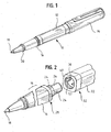
Fig. 1 is a perspective view of a writing instrument; -
Fig. 2 is a partially exploded, cut-away view, showing the engagement mechanism of first and second barrel portions of the writing instrument ofFig. 1 ; -
Fig. 3 is an enlarged perspective view, partially broken away for clarity, of an engagement mechanism of the first and second barrel portions of the writing instrument ofFig. 1 , just prior to insertion of each of two male projections extending laterally from a docking collar extending from an engagement end of one of the barrel portions into an entrance of a complementary track (shown in phantom lines) provided in an engagement end of the other barrel portion; -
Fig. 4 is an enlarged perspective view, partially broken away for clarity, of the engagement mechanism of the first and second barrel portions of the writing instrument shown inFig. 3 , in which each of the two male projections extending laterally from a docking collar extending from an engagement end of one of the barrel portions reaches an intersection within the complementary track (shown substantially in phantom lines and partially in solid lines) provided in the engagement end of the other barrel portion; -
Fig. 5 is an enlarged perspective view, partially broken away for clarity, of the engagement mechanism of the first and second barrel portions shown inFigs. 3 and 4 , in which each of the male projections extending laterally from a docking collar extending from the engagement end of one of the barrel portions reaches a position just before entering a widened terminus of the complementary track (shown substantially in phantom lines and partially in solid lines) of the engagement end of the other barrel portion; -
Fig. 6 is an enlarged cross-section view, taken along lines 6-6 ofFig. 5 , showing one of the male projections extending laterally from a docking collar extending from the engagement end of one of the barrel portions just before entering a widened terminus of the complementary track of the engagement end of the other barrel portion; -
Fig. 7 is a cross-sectional view similar toFig. 6 , showing the male projection received in the widened terminus of the complementary track. -
Fig. 8 is an exploded view of components of an engagement mechanism of a writing instrument shown inFigs. 3-7 ; and -
Fig. 9 is a cross-sectional view showing the first and second barrel portions of the writing instrument ofFig. 1 engaged with one another, utilizing the engagement mechanism shown inFigs. 3-7 and the components shown inFig. 8 . - With reference to the drawing figures, a
writing instrument 10 includes amain body 12 and acap 14. Themain body 12 includes afirst barrel portion 16 having awriting tip 18 projecting from afirst end 20. Themain body 12 further includes asecond barrel portion 22. Thefirst barrel portion 16 andsecond barrel portion 22 are provided with an engagement mechanism that is easily releasable, as compared to threaded engagement mechanisms conventionally used in writing instruments. The engagement mechanism includes at least onemale projection 24 extending laterally outwardly from acylindrical docking collar 26 extending from asecond end 28 of thefirst barrel portion 16, with thecylindrical docking collar 26 extending coaxially with thefirst barrel portion 16. In the embodiment shown in the drawing figures, twomale projections 24 are provided on thedocking collar 26, disposed opposite one another on the surface of thecylindrical docking collar 26. - For each
male projection 24, at least onecomplementary track 30 is provided in anengagement end 32 of thesecond barrel portion 22. Eachtrack 30 includes anentrance 34 to receive one of themale projections 24. Eachtrack 30 extends in a first direction, such as axially, along the length of thewriting instrument 10, until thetrack 30 reaches anintersection 36. At theintersection 36, thetrack 30 extends in at least one direction other than the first direction, until thetrack 30 reaches aterminus 38 thereof. At theterminus 38, thetrack 30 may widen, for example, in a direction toward theentrance 34. - It is recognized that the
cylindrical docking collar 26 having the male projection(s) 24 need not be associated with thesecond end 28, or engagement end, of thefirst barrel portion 16 having the writing tip 18 (not part of the present invention). For example, the cylindrical docking collar and male projection(s) 24 may instead be associated with theengagement end 32 of thesecond barrel portion 22, and the complementary track(s) 30 may be associated with thesecond end 28 of the first barrel portion 16 (not part of the present invention). Alternatively, the male projection(s) 24 need not be provided on thedocking collar 26, but may project laterally inwardly from an inside of one of the first andsecond barrel portions second barrel portions 16, 22 (not part of the present invention). - Operation of the engagement mechanism is sequentially depicted in
Figs. 3-7 . InFig. 3 , thefirst barrel portion 16 andsecond barrel portion 22 are arranged such that each of themale projections 24 is aligned with anentrance 34 of atrack 30. In the embodiment shown in the drawing figures, the twomale projections 24 are of the same size, and the twotracks 30 are of the same dimensions, such that there are two initial relative positions of the first andsecond barrel portions male projections 24 is properly aligned with anentrance 34 of atrack 30. - If it was desired to limit the user to one possible initial relative position of the first and
second barrel portions - Similarly, if it was desired to increase the number of possible initial relative positions of the first and
second barrel portions second barrel portions second barrel portions - After each of the
male projections 24 is aligned with the entrance of arespective track 30, thefirst barrel portion 16 is advanced in the direction toward thesecond barrel portion 22, as indicated by the arrows inFig. 3 . Each of themale projections 24 moves into theentrance 34 of therespective track 30, and as the user continues to move thefirst barrel portion 16 toward thesecond barrel portion 22, eachmale projection 24 follows therespective track 30 in the first direction until themale projection 24 reaches theintersection 36, as shown inFig. 4 . - The user then turns the
first barrel portion 16 relative to thesecond barrel portion 22, as indicated by the curved arrow inFig. 5 , so that eachmale projection 24 travels along therespective track 30 in a second direction until themale projection 24 reaches theterminus 38 of thetrack 30. InFig. 5 andFig. 6 (which is a cross-sectional view taken along lines 6-6 ofFig. 5 ) themale projections 24 are shown just before entering theterminus 38.Fig. 7 is a cross-sectional view similar toFig. 6 , but showing one of themale projections 24 received in theterminus 38. Thetracks 30 shown in the drawings are shaped such that the user need only turn thefirst barrel portion 16 relative to thesecond barrel portion 22 less than 360°, and more specifically, no more than about ninety degrees, in order to secure the first andsecond barrel portions - The
terminus 38 of eachtrack 30 is widened in a direction other than the second direction, such as in a direction toward the entrance of thetrack 30, i.e. toward theengagement end 32 of thesecond barrel portion 22. When themale projection 24 reaches the widenedterminus 38 of thetrack 30, as shown inFig. 7 , themale projection 24 pops into the widenedterminus 38, thereby securing thefirst barrel 16 andsecond barrel 22 into a releasably locked engagement with one another. The user may hear an audible clicking sound, and/or feel a tactile sensation upon the male projection popping into the widenedterminus 38. - In order to ensure that each
male projection 24 pops into the widenedterminus 38, a biasing element is provided. In the embodiment shown in the drawings, the biasing element is a deformable, shape-recoverable gasket 52. Thegasket 52 is disposed in thesecond barrel portion 22, posteriorly (i.e., farther away from the writingtip 18 if the writinginstrument 10 were fully assembled) of anengagement surface 40 at theengagement end 32 of thesecond barrel portion 22. Thetracks 30 are provided in a track-carryingmember 44 which is axially movable, to a limited extent, within thesecond barrel portion 22. The track-carryingmember 44 is disposed posteriorly of thegasket 52, and is biased (by the gasket) in an axial direction away from theengagement surface 40. - The
second end 28 of thefirst barrel portion 16 is also provided with anengagement contact surface 42. The axial distance between themale projections 24 and theengagement contact surface 42 is represented by the reference indicator d1 in the drawing figures, as best seen inFig. 3 . The section of each of thetracks 30 extending between theintersection 36 and the widenedterminus 38 may be gradually sloped in a direction away from theentrance 34, such that as thefirst barrel portion 16 is turned relative to thesecond barrel portion 22, the axial distance from the track to theengagement surface 40 gradually increases from less than d1 (as best seen inFig. 4 , wherein themale projections 24 are at therespective intersections 36 of thetrack members 30, and a short distance still separatesengagement surface 40 from engagement surface 42), to just slightly greater than d1. - With such geometry, once the
first barrel portion 16 is turned relative to thesecond barrel portion 22 to the point of contact of the engagement surfaces 40, 42, continued turning of thefirst barrel portion 16 relative to thesecond barrel portion 22 causes themale projections 24, constrained in thetracks 30, to impart forces which pull the track-carryingmember 44 axially toward the engagement surface 40 (as indicated by the downwardly-directed arrows inFig. 6 ), against the biasing force of thegasket 52. This pulling of the track-carryingmember 44 toward theengagement surface 40 continues until themale projections 24 reach the widenedterminus 38 of therespective track 30, as shown inFig. 7 , upon which the restoring force of thegasket 52 pushes the track-carrying member axially away from the engagement surface 40 (as indicated by the upwardly-directed arrows inFig. 7 ), bringing a lower side of themale projection 24 into contact with the wall of the widenedterminus 38. - In order to separate the first and
second barrel portions first barrel portion 16 relative to thesecond barrel portion 22, causing the withdrawal of each of themale projections 24 from the widenedterminus 38 of therespective track 30. The user continues turning thefirst barrel portion 16 until themale projections 24 reach theintersections 36. The user then pulls thefirst barrel portion 16 andsecond barrel portion 22 axially away from one another until the first andsecond barrel portions instrument 10 so as to provide access to, for example, an ink reservoir stored therein. - Various components may be employed in a writing instrument to achieve the selective engagement mechanism disclosed herein. In
Figs. 8 and 9 , an exemplary set of components is shown. Thedocking collar 26 having a pair ofmale projections 24 extending laterally outwardly therefrom is shown in the exploded view ofFigure 8 . An anterior portion of thedocking collar 26 is received in a first barrelportion retaining member 54, which serves to retain thedocking collar 26 at thesecond end 28 of thefirst barrel portion 16. Theengagement surface 42 of thefirst barrel portion 16 is preferably provided on the first barrelportion retaining member 54. - The track-carrying
member 44 and thegasket 52 are received in a second barrelportion retaining member 50, which serves to retain the track-carryingmember 44 andgasket 52 near theengagement end 32 of thesecond barrel portion 22. Theengagement surface 40 of thesecond barrel portion 22 is preferably provided on the second barrelportion retaining member 50. - In order to prevent rotation of the track-carrying
member 44 relative to thesecond barrel portion 22, the track-carrying member may be provided with a rotation-limitingchannel 56, as shown inFig. 8 . A rotation-preventing projection (not shown) which is fixed relative to the inside of thesecond barrel portion 22 is received in the rotation-limiting channel. - It is recognized that writing instruments of various cross-sectional exterior shapes would benefit from the quick-release selective engagement mechanism of the present disclosure. The writing
instrument 10 depicted in the drawing figures has a generally rectangular cross-sectional exterior shape. The selective engagement mechanism disclosed herein is particularly well suited to maintaining axial alignment of the first andsecond barrel portions Fig. 8 , in order to prevent the rotation of the track-carryingmember 44, the rotation-preventing projection (not shown) may be provided in arectangular insert 46, or in a cylindrical-to-rectangular adapter member 58. Thedocking collar 26 and the track-carryingmember 44 are preferably made of a precision-machined metal, with themale projections 24 preferably being integral extensions of thedocking collar 26. The first barrelportion retaining member 54 and second barrelportion retaining member 50 are also preferably made of a precision-machined metal. - While certain embodiments are specifically described herein, the present disclosure is not intended to be limited thereto, and it is recognized that variations may be made that are within the scope of the appended claims.
Claims (5)
- A writing instrument (10) comprising:a first barrel portion (16) having a writing tip (18) projecting from a first end (20) thereof;a second barrel portion (22) selectively engageable with the first barrel portion (16);a releasable locking mechanism to secure the first barrel portion (16) and second barrel portion (22) together;a docking collar (26) associated with the releasable locking mechanism and extending from an end of the first barrel portion (16) opposite the end from which the writing tip (18) projects;at least one male projection (24) extending laterally from the docking collar (26);a track-carrying member (44) associated with the second barrel portion (22) and axially movable within its respective barrel portion;at least one complementary track (30) associated with the track-carrying member (44), wherein the at least one complementary track (30) is sized to receive the at least one male projection (24) and shaped to constrain movement of the at least one male projection (24) along the at least one complementary track (30) including limiting the at least one male projection (24) to less than 360 degrees of rotation to have selective engagement of the first and second barrel portions by turning one of the first and second barrel portions relative to the other of the first and second barrel portions; and a biasing element (52) associated with the track-carrying member (44), the biasing element (52) biasing the track-carrying member (44) away from an engagement surface (40) of the second barrel portion (22).
- The writing instrument of claim 1, wherein the biasing element is a deformable, shape recoverable gasket (52).
- The writing instrument of claim 1, wherein, while selectively engaging the first barrel portion (16) and second barrel portion (22), the track-carrying member (44) is forced in a direction opposing the biasing element upon turning the first barrel portion (16) relative to the second barrel portion (22).
- The writing instrument (10) of claim 1, wherein the releaseable locking mechanism consists of
a securement mechanism including the at least one male projection (24) associated with an engagement end (28) of the first barrel portion (16);
the track-carrying member (44) being disposed in an engagement end (32) of the second barrel portion (22), the track-carrying member (44) being axially movable within the engagement end (32) of the second barrel portion;
the at least one complementary track (30) provided in the track-carrying member (44) and associated with the engagement end (32) of the second barrel portion (22);
the engagement surface (40) associated with the engagement end (32) of the second barrel portion in which the track-carrying member (44) is disposed; and
a gasket (52) disposed between the track-carrying member (44) and the engagement surface (40), wherein the gasket biases the track-carrying member (44) away from the engagement surface (40) of the second barrel portion (22) to facilitate securement of the first barrel portion (16) and second barrel portion (22). - The writing instrument of claim 4, wherein the at least one complementary track (30) includes an entrance (34) open in a direction toward the engagement surface (40) of the second barrel portion in which the track-carrying member (44) is disposed and a terminus (38) that widens in the direction toward the engagement surface (40).
Applications Claiming Priority (2)
| Application Number | Priority Date | Filing Date | Title |
|---|---|---|---|
| US11/184,106 US7461991B2 (en) | 2005-07-19 | 2005-07-19 | Quick release mechanism for access to ink reservoir of writing instrument |
| PCT/IB2005/002905 WO2007010323A1 (en) | 2005-07-19 | 2005-09-29 | Quick release mechanism for access to ink reservoir of writing instrument |
Publications (2)
| Publication Number | Publication Date |
|---|---|
| EP1910092A1 EP1910092A1 (en) | 2008-04-16 |
| EP1910092B1 true EP1910092B1 (en) | 2014-11-12 |
Family
ID=35717518
Family Applications (1)
| Application Number | Title | Priority Date | Filing Date |
|---|---|---|---|
| EP05808249.6A Expired - Lifetime EP1910092B1 (en) | 2005-07-19 | 2005-09-29 | Quick release mechanism for access to ink reservoir of writing instrument |
Country Status (8)
| Country | Link |
|---|---|
| US (1) | US7461991B2 (en) |
| EP (1) | EP1910092B1 (en) |
| JP (1) | JP4847524B2 (en) |
| KR (1) | KR20080031411A (en) |
| CN (1) | CN100584640C (en) |
| AU (1) | AU2005334692A1 (en) |
| BR (1) | BRPI0520430A2 (en) |
| WO (1) | WO2007010323A1 (en) |
Families Citing this family (14)
| Publication number | Priority date | Publication date | Assignee | Title |
|---|---|---|---|---|
| USD611094S1 (en) * | 2008-03-04 | 2010-03-02 | Benoit Collin | Writing instrument |
| USD628636S1 (en) * | 2008-07-14 | 2010-12-07 | Beifa Group Co., Ltd. | Pen |
| USD628640S1 (en) * | 2008-07-14 | 2010-12-07 | Beifa Group Co., Ltd. | Pen |
| USD605693S1 (en) * | 2008-12-11 | 2009-12-08 | Vanker Industries Limited | Set of markers |
| US20110053694A1 (en) * | 2009-08-27 | 2011-03-03 | Wood Robert P | Hand-held anti-assault weapon |
| USD701267S1 (en) * | 2012-02-14 | 2014-03-18 | J.S. Staedtler Gmbh & Co. Kg | Writing implement |
| FR2995247B1 (en) * | 2012-09-11 | 2015-02-20 | Bic Soc | WRITING INSTRUMENT WITH SIMPLIFIED ASSEMBLY |
| FR2995246B1 (en) * | 2012-09-11 | 2014-09-05 | Bic Soc | ERGONOMIC AND VERSATILE WRITING INSTRUMENT |
| USD733220S1 (en) * | 2013-01-25 | 2015-06-30 | J.S. Staedtler Gmbh & Co. Kg | Pencil with stylus |
| CN105966115B (en) * | 2016-06-28 | 2017-10-10 | 宁波市文魁控股集团有限公司 | The penholder component that can quickly assemble |
| USD873916S1 (en) | 2018-03-21 | 2020-01-28 | Staples Brands, Inc. | Writing instrument |
| USD912142S1 (en) * | 2018-12-03 | 2021-03-02 | Beifa Group Co., Ltd. | Pen |
| JP7680295B2 (en) * | 2021-07-15 | 2025-05-20 | ゼブラ株式会社 | writing implements |
| USD1077908S1 (en) * | 2024-02-07 | 2025-06-03 | Shuaishuai Hu | Multifunctional pen |
Family Cites Families (25)
| Publication number | Priority date | Publication date | Assignee | Title |
|---|---|---|---|---|
| DE760854C (en) | 1940-04-18 | 1952-09-22 | Richard Lottermoser | Pen or pen holder |
| BE476103A (en) * | 1946-07-17 | |||
| US2750926A (en) * | 1953-08-14 | 1956-06-19 | Scripto Inc | Retracting mechanism for ball point pens and the like |
| US2917024A (en) * | 1957-01-04 | 1959-12-15 | Edward I Westmoreland | Pneumatically-filled fountain pen |
| GB878104A (en) | 1957-11-29 | 1961-09-27 | Erich Barthe | Improvements in or relating to reservoir pens |
| GB1041630A (en) * | 1964-09-15 | 1966-09-07 | Edmundo Naftalion Dorna | A composite writing utensil |
| USD250478S (en) * | 1976-09-11 | 1978-12-05 | Moriz Hausch Gmbh | Writing pen |
| USD254912S (en) * | 1978-05-16 | 1980-05-06 | Pilot Man-Nen Hitsu Kabushiki Kaisha | Fountain pen |
| US4533271A (en) * | 1983-10-12 | 1985-08-06 | Nick Sansevero | Writing instrument with plural implements cam actuated |
| US4755075A (en) * | 1987-02-25 | 1988-07-05 | Tae Yoon Leem | Writing implement with tip having attaching projections |
| JPH0635232B2 (en) * | 1987-12-28 | 1994-05-11 | 富士産業株式会社 | Writing instrument |
| USD321207S (en) * | 1988-11-30 | 1991-10-29 | Dennison Manufacturing Company | Retractable marker pen |
| US4974982A (en) * | 1990-02-22 | 1990-12-04 | Nielson Thomas W | Keyring pocket pen |
| USD339378S (en) * | 1990-09-25 | 1993-09-14 | Waterman S.A. | Ball-point pen |
| JP2556076Y2 (en) * | 1991-05-21 | 1997-12-03 | パイロットプレシジョン株式会社 | mechanical pencil |
| JP2605614Y2 (en) * | 1992-02-04 | 2000-07-31 | 株式会社壽 | Ballpoint pen |
| US5642953A (en) * | 1993-11-02 | 1997-07-01 | Mitsubishi Pencil Kabushiki Kaisha | Multiplex writing implement |
| JP3505308B2 (en) * | 1995-03-06 | 2004-03-08 | 株式会社サクラクレパス | Writing implement, manufacturing method of writing implement and fitting structure of male and female members |
| IT1304886B1 (en) * | 1998-07-31 | 2001-04-05 | Visconti S R L | DOUBLE TANK FOUNTAIN PEN WITH FILLING PISTON |
| USD440603S1 (en) * | 2000-03-03 | 2001-04-17 | S. T. Dupont S.A | Ball point pen |
| CN2487556Y (en) * | 2001-07-13 | 2002-04-24 | 陈谞 | Telescopic pen |
| US6860616B2 (en) * | 2001-12-14 | 2005-03-01 | Iq Hong Kong, Ltd. | Ultraviolet light writing system |
| CN2631774Y (en) * | 2003-08-08 | 2004-08-11 | 黄明 | Rotary control luminous pen |
| US8104983B2 (en) * | 2003-11-11 | 2012-01-31 | Societe Bic | Combination writing instrument |
| USD504154S1 (en) * | 2004-02-02 | 2005-04-19 | Waterman Sas | Writing instrument |
-
2005
- 2005-07-19 US US11/184,106 patent/US7461991B2/en active Active
- 2005-09-29 KR KR1020087003582A patent/KR20080031411A/en not_active Withdrawn
- 2005-09-29 JP JP2008522076A patent/JP4847524B2/en not_active Expired - Fee Related
- 2005-09-29 BR BRPI0520430-5A patent/BRPI0520430A2/en not_active IP Right Cessation
- 2005-09-29 CN CN200580051101A patent/CN100584640C/en not_active Expired - Lifetime
- 2005-09-29 WO PCT/IB2005/002905 patent/WO2007010323A1/en not_active Ceased
- 2005-09-29 EP EP05808249.6A patent/EP1910092B1/en not_active Expired - Lifetime
- 2005-09-29 AU AU2005334692A patent/AU2005334692A1/en not_active Abandoned
Also Published As
| Publication number | Publication date |
|---|---|
| HK1122772A1 (en) | 2009-05-29 |
| AU2005334692A1 (en) | 2007-01-25 |
| BRPI0520430A2 (en) | 2009-09-29 |
| KR20080031411A (en) | 2008-04-08 |
| US7461991B2 (en) | 2008-12-09 |
| US20070071539A1 (en) | 2007-03-29 |
| CN101242962A (en) | 2008-08-13 |
| WO2007010323A1 (en) | 2007-01-25 |
| JP2009501652A (en) | 2009-01-22 |
| EP1910092A1 (en) | 2008-04-16 |
| JP4847524B2 (en) | 2011-12-28 |
| CN100584640C (en) | 2010-01-27 |
Similar Documents
| Publication | Publication Date | Title |
|---|---|---|
| US7461991B2 (en) | Quick release mechanism for access to ink reservoir of writing instrument | |
| US11679523B2 (en) | Coupling system | |
| JP3595766B2 (en) | Pipe fittings | |
| US20120183331A1 (en) | Transmission device for photo conductor drum | |
| EP2261889A2 (en) | Percussion instrument bracket systems | |
| US20020072436A1 (en) | Baseball bat with a ball-serving device | |
| US7905675B2 (en) | Connecting member | |
| US20090297250A1 (en) | Pen cap and pen barrel coupling structure | |
| US20170294741A1 (en) | Bayonet connector and methods for incorporating bayonet connector | |
| JP6365534B2 (en) | Cell collection device | |
| JP2009266454A (en) | Operation knob | |
| JP2010178865A (en) | Skipping rope | |
| CN108602378B (en) | Writing Instrument with Self-Blocking Assembly | |
| US20150273932A1 (en) | Retractable Writing Instrument | |
| JP5012058B2 (en) | Writing instrument clip | |
| US20210039153A1 (en) | Quick connect mechanisms for draw stud assemblies | |
| HK1122772B (en) | Quick release mechanism for access to ink reservoir of writing instrument | |
| US7392803B2 (en) | Fixing ring structure for a barrel of a toy gun | |
| MX2008000804A (en) | Quick release mechanism for access to ink reservoir of writing instrument | |
| JP4783913B2 (en) | File, binding tool and baffle | |
| JP2005145003A (en) | Pocket writing utensil | |
| KR200379044Y1 (en) | Doughnut-type tape measure attachable with writing material | |
| JP4080433B2 (en) | Pipe fitting | |
| WO2025100395A1 (en) | Writing instrument | |
| JPH08170615A (en) | Pipe connecting mechanism |
Legal Events
| Date | Code | Title | Description |
|---|---|---|---|
| PUAI | Public reference made under article 153(3) epc to a published international application that has entered the european phase |
Free format text: ORIGINAL CODE: 0009012 |
|
| 17P | Request for examination filed |
Effective date: 20080111 |
|
| AK | Designated contracting states |
Kind code of ref document: A1 Designated state(s): AT BE BG CH CY CZ DE DK EE ES FI FR GB GR HU IE IS IT LI LT LU LV MC NL PL PT RO SE SI SK TR |
|
| 17Q | First examination report despatched |
Effective date: 20101104 |
|
| DAX | Request for extension of the european patent (deleted) | ||
| REG | Reference to a national code |
Ref country code: DE Ref legal event code: R079 Ref document number: 602005045173 Country of ref document: DE Free format text: PREVIOUS MAIN CLASS: B43K0005000000 Ipc: B43K0007000000 |
|
| RIC1 | Information provided on ipc code assigned before grant |
Ipc: B43K 5/00 20060101ALI20140409BHEP Ipc: B43K 7/00 20060101AFI20140409BHEP Ipc: B43K 8/00 20060101ALI20140409BHEP |
|
| GRAP | Despatch of communication of intention to grant a patent |
Free format text: ORIGINAL CODE: EPIDOSNIGR1 |
|
| INTG | Intention to grant announced |
Effective date: 20140520 |
|
| GRAS | Grant fee paid |
Free format text: ORIGINAL CODE: EPIDOSNIGR3 |
|
| GRAA | (expected) grant |
Free format text: ORIGINAL CODE: 0009210 |
|
| AK | Designated contracting states |
Kind code of ref document: B1 Designated state(s): AT BE BG CH CY CZ DE DK EE ES FI FR GB GR HU IE IS IT LI LT LU LV MC NL PL PT RO SE SI SK TR |
|
| REG | Reference to a national code |
Ref country code: GB Ref legal event code: FG4D |
|
| REG | Reference to a national code |
Ref country code: CH Ref legal event code: EP |
|
| REG | Reference to a national code |
Ref country code: AT Ref legal event code: REF Ref document number: 695502 Country of ref document: AT Kind code of ref document: T Effective date: 20141115 |
|
| REG | Reference to a national code |
Ref country code: IE Ref legal event code: FG4D |
|
| REG | Reference to a national code |
Ref country code: DE Ref legal event code: R096 Ref document number: 602005045173 Country of ref document: DE Effective date: 20141224 |
|
| REG | Reference to a national code |
Ref country code: NL Ref legal event code: VDEP Effective date: 20141112 |
|
| REG | Reference to a national code |
Ref country code: AT Ref legal event code: MK05 Ref document number: 695502 Country of ref document: AT Kind code of ref document: T Effective date: 20141112 |
|
| PG25 | Lapsed in a contracting state [announced via postgrant information from national office to epo] |
Ref country code: PT Free format text: LAPSE BECAUSE OF FAILURE TO SUBMIT A TRANSLATION OF THE DESCRIPTION OR TO PAY THE FEE WITHIN THE PRESCRIBED TIME-LIMIT Effective date: 20150312 Ref country code: FI Free format text: LAPSE BECAUSE OF FAILURE TO SUBMIT A TRANSLATION OF THE DESCRIPTION OR TO PAY THE FEE WITHIN THE PRESCRIBED TIME-LIMIT Effective date: 20141112 Ref country code: NL Free format text: LAPSE BECAUSE OF FAILURE TO SUBMIT A TRANSLATION OF THE DESCRIPTION OR TO PAY THE FEE WITHIN THE PRESCRIBED TIME-LIMIT Effective date: 20141112 Ref country code: IS Free format text: LAPSE BECAUSE OF FAILURE TO SUBMIT A TRANSLATION OF THE DESCRIPTION OR TO PAY THE FEE WITHIN THE PRESCRIBED TIME-LIMIT Effective date: 20150312 Ref country code: LT Free format text: LAPSE BECAUSE OF FAILURE TO SUBMIT A TRANSLATION OF THE DESCRIPTION OR TO PAY THE FEE WITHIN THE PRESCRIBED TIME-LIMIT Effective date: 20141112 Ref country code: ES Free format text: LAPSE BECAUSE OF FAILURE TO SUBMIT A TRANSLATION OF THE DESCRIPTION OR TO PAY THE FEE WITHIN THE PRESCRIBED TIME-LIMIT Effective date: 20141112 |
|
| PG25 | Lapsed in a contracting state [announced via postgrant information from national office to epo] |
Ref country code: PL Free format text: LAPSE BECAUSE OF FAILURE TO SUBMIT A TRANSLATION OF THE DESCRIPTION OR TO PAY THE FEE WITHIN THE PRESCRIBED TIME-LIMIT Effective date: 20141112 Ref country code: CY Free format text: LAPSE BECAUSE OF FAILURE TO SUBMIT A TRANSLATION OF THE DESCRIPTION OR TO PAY THE FEE WITHIN THE PRESCRIBED TIME-LIMIT Effective date: 20141112 Ref country code: SE Free format text: LAPSE BECAUSE OF FAILURE TO SUBMIT A TRANSLATION OF THE DESCRIPTION OR TO PAY THE FEE WITHIN THE PRESCRIBED TIME-LIMIT Effective date: 20141112 Ref country code: LV Free format text: LAPSE BECAUSE OF FAILURE TO SUBMIT A TRANSLATION OF THE DESCRIPTION OR TO PAY THE FEE WITHIN THE PRESCRIBED TIME-LIMIT Effective date: 20141112 Ref country code: GR Free format text: LAPSE BECAUSE OF FAILURE TO SUBMIT A TRANSLATION OF THE DESCRIPTION OR TO PAY THE FEE WITHIN THE PRESCRIBED TIME-LIMIT Effective date: 20150213 Ref country code: AT Free format text: LAPSE BECAUSE OF FAILURE TO SUBMIT A TRANSLATION OF THE DESCRIPTION OR TO PAY THE FEE WITHIN THE PRESCRIBED TIME-LIMIT Effective date: 20141112 |
|
| PG25 | Lapsed in a contracting state [announced via postgrant information from national office to epo] |
Ref country code: SK Free format text: LAPSE BECAUSE OF FAILURE TO SUBMIT A TRANSLATION OF THE DESCRIPTION OR TO PAY THE FEE WITHIN THE PRESCRIBED TIME-LIMIT Effective date: 20141112 Ref country code: EE Free format text: LAPSE BECAUSE OF FAILURE TO SUBMIT A TRANSLATION OF THE DESCRIPTION OR TO PAY THE FEE WITHIN THE PRESCRIBED TIME-LIMIT Effective date: 20141112 Ref country code: RO Free format text: LAPSE BECAUSE OF FAILURE TO SUBMIT A TRANSLATION OF THE DESCRIPTION OR TO PAY THE FEE WITHIN THE PRESCRIBED TIME-LIMIT Effective date: 20141112 Ref country code: CZ Free format text: LAPSE BECAUSE OF FAILURE TO SUBMIT A TRANSLATION OF THE DESCRIPTION OR TO PAY THE FEE WITHIN THE PRESCRIBED TIME-LIMIT Effective date: 20141112 Ref country code: DK Free format text: LAPSE BECAUSE OF FAILURE TO SUBMIT A TRANSLATION OF THE DESCRIPTION OR TO PAY THE FEE WITHIN THE PRESCRIBED TIME-LIMIT Effective date: 20141112 |
|
| REG | Reference to a national code |
Ref country code: DE Ref legal event code: R097 Ref document number: 602005045173 Country of ref document: DE |
|
| PLBE | No opposition filed within time limit |
Free format text: ORIGINAL CODE: 0009261 |
|
| STAA | Information on the status of an ep patent application or granted ep patent |
Free format text: STATUS: NO OPPOSITION FILED WITHIN TIME LIMIT |
|
| 26N | No opposition filed |
Effective date: 20150813 |
|
| PG25 | Lapsed in a contracting state [announced via postgrant information from national office to epo] |
Ref country code: IT Free format text: LAPSE BECAUSE OF FAILURE TO SUBMIT A TRANSLATION OF THE DESCRIPTION OR TO PAY THE FEE WITHIN THE PRESCRIBED TIME-LIMIT Effective date: 20141112 |
|
| PG25 | Lapsed in a contracting state [announced via postgrant information from national office to epo] |
Ref country code: SI Free format text: LAPSE BECAUSE OF FAILURE TO SUBMIT A TRANSLATION OF THE DESCRIPTION OR TO PAY THE FEE WITHIN THE PRESCRIBED TIME-LIMIT Effective date: 20141112 |
|
| PG25 | Lapsed in a contracting state [announced via postgrant information from national office to epo] |
Ref country code: LU Free format text: LAPSE BECAUSE OF FAILURE TO SUBMIT A TRANSLATION OF THE DESCRIPTION OR TO PAY THE FEE WITHIN THE PRESCRIBED TIME-LIMIT Effective date: 20150929 Ref country code: MC Free format text: LAPSE BECAUSE OF FAILURE TO SUBMIT A TRANSLATION OF THE DESCRIPTION OR TO PAY THE FEE WITHIN THE PRESCRIBED TIME-LIMIT Effective date: 20141112 |
|
| REG | Reference to a national code |
Ref country code: CH Ref legal event code: PL |
|
| REG | Reference to a national code |
Ref country code: IE Ref legal event code: MM4A |
|
| PG25 | Lapsed in a contracting state [announced via postgrant information from national office to epo] |
Ref country code: IE Free format text: LAPSE BECAUSE OF NON-PAYMENT OF DUE FEES Effective date: 20150929 Ref country code: CH Free format text: LAPSE BECAUSE OF NON-PAYMENT OF DUE FEES Effective date: 20150930 Ref country code: LI Free format text: LAPSE BECAUSE OF NON-PAYMENT OF DUE FEES Effective date: 20150930 |
|
| REG | Reference to a national code |
Ref country code: FR Ref legal event code: PLFP Year of fee payment: 12 |
|
| PGFP | Annual fee paid to national office [announced via postgrant information from national office to epo] |
Ref country code: DE Payment date: 20160928 Year of fee payment: 12 |
|
| PG25 | Lapsed in a contracting state [announced via postgrant information from national office to epo] |
Ref country code: BG Free format text: LAPSE BECAUSE OF FAILURE TO SUBMIT A TRANSLATION OF THE DESCRIPTION OR TO PAY THE FEE WITHIN THE PRESCRIBED TIME-LIMIT Effective date: 20141112 Ref country code: HU Free format text: LAPSE BECAUSE OF FAILURE TO SUBMIT A TRANSLATION OF THE DESCRIPTION OR TO PAY THE FEE WITHIN THE PRESCRIBED TIME-LIMIT; INVALID AB INITIO Effective date: 20050929 |
|
| PG25 | Lapsed in a contracting state [announced via postgrant information from national office to epo] |
Ref country code: TR Free format text: LAPSE BECAUSE OF FAILURE TO SUBMIT A TRANSLATION OF THE DESCRIPTION OR TO PAY THE FEE WITHIN THE PRESCRIBED TIME-LIMIT Effective date: 20141112 |
|
| REG | Reference to a national code |
Ref country code: FR Ref legal event code: PLFP Year of fee payment: 13 |
|
| PG25 | Lapsed in a contracting state [announced via postgrant information from national office to epo] |
Ref country code: BE Free format text: LAPSE BECAUSE OF FAILURE TO SUBMIT A TRANSLATION OF THE DESCRIPTION OR TO PAY THE FEE WITHIN THE PRESCRIBED TIME-LIMIT Effective date: 20141112 |
|
| REG | Reference to a national code |
Ref country code: DE Ref legal event code: R119 Ref document number: 602005045173 Country of ref document: DE |
|
| PG25 | Lapsed in a contracting state [announced via postgrant information from national office to epo] |
Ref country code: DE Free format text: LAPSE BECAUSE OF NON-PAYMENT OF DUE FEES Effective date: 20180404 |
|
| REG | Reference to a national code |
Ref country code: FR Ref legal event code: PLFP Year of fee payment: 14 |
|
| REG | Reference to a national code |
Ref country code: GB Ref legal event code: 732E Free format text: REGISTERED BETWEEN 20220203 AND 20220209 |
|
| PGFP | Annual fee paid to national office [announced via postgrant information from national office to epo] |
Ref country code: GB Payment date: 20240927 Year of fee payment: 20 |
|
| PGFP | Annual fee paid to national office [announced via postgrant information from national office to epo] |
Ref country code: FR Payment date: 20240925 Year of fee payment: 20 |
|
| REG | Reference to a national code |
Ref country code: GB Ref legal event code: PE20 Expiry date: 20250928 |