EP1908950B1 - Druckausgleichssteuerung für eine Gasturbinenmotordüse - Google Patents
Druckausgleichssteuerung für eine Gasturbinenmotordüse Download PDFInfo
- Publication number
- EP1908950B1 EP1908950B1 EP07252954A EP07252954A EP1908950B1 EP 1908950 B1 EP1908950 B1 EP 1908950B1 EP 07252954 A EP07252954 A EP 07252954A EP 07252954 A EP07252954 A EP 07252954A EP 1908950 B1 EP1908950 B1 EP 1908950B1
- Authority
- EP
- European Patent Office
- Prior art keywords
- nozzle
- pressure
- pressurized air
- air
- actuator
- Prior art date
- Legal status (The legal status is an assumption and is not a legal conclusion. Google has not performed a legal analysis and makes no representation as to the accuracy of the status listed.)
- Ceased
Links
Images

Classifications
-
- F—MECHANICAL ENGINEERING; LIGHTING; HEATING; WEAPONS; BLASTING
- F02—COMBUSTION ENGINES; HOT-GAS OR COMBUSTION-PRODUCT ENGINE PLANTS
- F02K—JET-PROPULSION PLANTS
- F02K1/00—Plants characterised by the form or arrangement of the jet pipe or nozzle; Jet pipes or nozzles peculiar thereto
- F02K1/06—Varying effective area of jet pipe or nozzle
- F02K1/15—Control or regulation
-
- F—MECHANICAL ENGINEERING; LIGHTING; HEATING; WEAPONS; BLASTING
- F02—COMBUSTION ENGINES; HOT-GAS OR COMBUSTION-PRODUCT ENGINE PLANTS
- F02K—JET-PROPULSION PLANTS
- F02K1/00—Plants characterised by the form or arrangement of the jet pipe or nozzle; Jet pipes or nozzles peculiar thereto
- F02K1/06—Varying effective area of jet pipe or nozzle
- F02K1/12—Varying effective area of jet pipe or nozzle by means of pivoted flaps
- F02K1/1223—Varying effective area of jet pipe or nozzle by means of pivoted flaps of two series of flaps, the upstream series having its flaps hinged at their upstream ends on a fixed structure and the downstream series having its flaps hinged at their upstream ends on the downstream ends of the flaps of the upstream series
-
- F—MECHANICAL ENGINEERING; LIGHTING; HEATING; WEAPONS; BLASTING
- F05—INDEXING SCHEMES RELATING TO ENGINES OR PUMPS IN VARIOUS SUBCLASSES OF CLASSES F01-F04
- F05D—INDEXING SCHEME FOR ASPECTS RELATING TO NON-POSITIVE-DISPLACEMENT MACHINES OR ENGINES, GAS-TURBINES OR JET-PROPULSION PLANTS
- F05D2270/00—Control
- F05D2270/30—Control parameters, e.g. input parameters
- F05D2270/301—Pressure
- F05D2270/3015—Pressure differential pressure
Definitions
- This application relates to a control for air pressure supplied to assist in balancing forces on a linkage for controlling a nozzle cross-sectional area in a gas turbine engine.
- a gas turbine engine includes a fan section, a compression section, a combustion section and a turbine section.
- An axis of the engine is centrally disposed along the engine and extends longitudinally through the sections.
- a primary flow path for working medium gases extends axially through the sections of the engine.
- the nozzle for the gas turbine engine may be provided with an actuation structure that can cause a plurality of flaps to pivot radially inwardly or outwardly to control the size of the nozzle opening.
- a hydraulic actuator drives a ring which is connected through linkages to the plurality of flaps.
- a control causes the actuator to move the flaps between various positions to provide a desired cross-sectional area.
- a prior art nozzle having the features of the preamble of claim 1, is disclosed in US-4420932 .
- Another prior art nozzle is shown in EP-0833047 .
- a nozzle for a gas turbine engine as claimed in claim 1 and a method of operating a gas turbine engine as claimed in claim 7.
- a control modulates the flow of pressurized air to the rear face of the ring based upon sensed system conditions.
- a pressure sensor senses the pressure within the nozzle and the ambient pressure, and may limit or block the flow of pressurized air to the ring when this ratio is relatively low. In one disclosed embodiment, should the ratio of engine pressure to ambient pressure be less than three, then the flow of pressurized air to the ring is reduced or eliminated.
- the control may be based upon a local controller, by the overall engine controller, or may be controlled simply by a pressure responsive valve acting upon the difference in pressure.
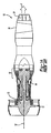
- Figure 1A shows a gas turbine engine 10.
- a fan section 11 moves air and rotates about an axial center line 12.
- a compressor section 13, a combustion section 14, and a turbine section 15 are also centered on the axial center line 12.
- a nozzle section 16 of the turbine discharges gas downstream.
- Figure 1A is a highly schematic view, however, it does show the main components of the gas turbine engine. Further, while a particular type of gas turbine engine is illustrated in this figure, it should be understood that the present invention extends to other types of gas turbine engines.
- a plurality of flaps 31 at the end of the nozzle 16 can be pivoted radially inwardly or outwardly to control the cross-sectional area at the nozzle.
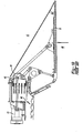
- This is, as known in the art, and an actuation structure for pivoting the flaps 31 is shown in Figure 1B .
- a hydraulic actuator 41 drives a sync ring 44 through a connection at 46.
- Air pressure 40 within the nozzle acts on an inner surface of the flaps 31, while an ambient pressure 42 outside the flaps 31 acts on an outer surface of the flaps 31.
- the air pressure at 40 is much greater than the ambient air pressure 42. This imbalance creates forces on the sync ring 44.
- pressurized air is delivered through openings 48 to the rear surface of the sync ring 44 to assist in handling the load.
- the pressure ratio between the areas 40 and 42 will be lower. This occurs, for example, at low altitude/low speed flying. In such instances, the force supplied through the openings 48 through the pressurized air on the rear surface of the sync ring 44 can be unduly high and can itself create undesirable loads and stresses on the various connections.
- an air supply tube 62 is provided with a valve 64, and which is controlled by a control 66.
- Control 66 may trigger the valve 64 either through a simple delta pressure control based upon the pressures at 40 and 42, or the control can be based upon an electronic control. In one application, it may be the controller for the entire engine. Essentially, should the pressure ratio between areas 40 and 42 be lower (e.g., less than three), then it would be desirable to block airflow to the sync ring 44, and instead open the cavity to a lower pressure source (e.g., atmosphere) as shown at 68.
- the hydraulic actuator 41 is omitted from the view but would preferably be included.
Landscapes
- Engineering & Computer Science (AREA)
- Chemical & Material Sciences (AREA)
- Combustion & Propulsion (AREA)
- Mechanical Engineering (AREA)
- General Engineering & Computer Science (AREA)
- Control Of Turbines (AREA)
- Turbine Rotor Nozzle Sealing (AREA)
- Supercharger (AREA)
Claims (9)
- Düse für eine Gasturbinenmaschine (10) umfassend:eine Mehrzahl von Klappen (31), die sich bewegen können, um einen gewünschten Querschnittsbereich für einen Düsenauslass bereitzustellen;eine Aktuatoranordnung zum Antreiben der Klappen (31) durch eine Verbindung, wobei die Aktuatoranordnung zumindest ein Aktuatorelement (41) beinhaltet, das die Klappen (31) durch eine Zwischenanordnung (44) bewegt; undeine Luftzufuhr zur Zuführung von druckbeaufschlagter Luft an eine Fläche der Zwischenanordnung (44), wobei die druckbeaufschlagte Luft das Aktuatorelement (41) bei dem Halten der Klappen (31) in einer gewünschten Position und bei dem Widerstehen einer Druckkraft innerhalb der Düse (60) unterstützt, ein Ventil (64) zum Steuern/ Regeln von Strömung druckbeaufschlagter Luft zu der Fläche der Zwischenanordnung (44) und eine Steuerung/ Regelung (66) für das Ventil (64), welche die Strömung von Luft reduziert, wenn bestimmte Systemzustände erkannt werden,dadurch gekennzeichnet, dass:ein Druckverhältnis zwischen dem Luftdruck innerhalb der Düse und einem Umgebungsdruck verwendet wird, um das Ventil zu steuern/regeln; unddie Zwischenanordnung (44) ein Synchronisationsring ist, der eine Kammer zur Aufnahme druckbeaufschlagter Luft bildet und mit dem Aktuatorelement (41) verbunden ist.
- Düse nach Anspruch 1, wobei die Strömung druckbeaufschlagter Luft zu der Fläche reduziert ist, wenn das Verhältnis geringer als drei ist.
- Düse nach Anspruch 1 oder 2, wobei das Aktuatorelement (41) ein Fluidaktuator ist.
- Düse nach einem der vorangehenden Ansprüche, wobei die Steuerung/ Regelung ein durch den Druckunterschied betätigtes Ventil ist.
- Düse nach einem der vorangehenden Ansprüche, wobei die Steuerung/ Regelung (66) Teil einer Gesamtsteuerung/ -regelung für eine Gasturbinenmaschine (10) ist.
- Düse nach einem der vorangehenden Ansprüche, wobei das Ventil (64) Luft in die Atmosphäre (68) abgibt, wenn der Strom von Luft zu dem Zwischenelement (44) zu reduzieren ist.
- Verfahren zum Betreiben einer Gasturbinenmaschine (10) umfassend die Schritte:Bereitstellen einer Aktuatoranordnung zum Antrieb von Klappen (31) durch eine Verbindung, um einen gewünschten Querschnittsbereich für einen Düsenauslass bereitzustellen, wobei die Aktuatoranordnung zumindest ein Aktuatorelement (41) beinhaltet, das die Klappen (31) durch eine Zwischenanordnung (44) bewegt; undZuführen druckbeaufschlagter Luft an eine Fläche der Zwischenanordnung (44), wobei die druckbeaufschlagte Luft das Aktuatorelement (41) beim Halten der Klappe (31) in einer gewünschten Position und beim Widerstehen einer Druckkraft innerhalb der Düse unterstützt, und Strömung druckbeaufschlagter Luft zu der Fläche der dazwischen liegenden Struktur (44) reduziert, wenn bestimmte Systemzustände erkannt werden,dadurch gekennzeichnet, dass:ein Druckverhältnis zwischen dem Luftdruck innerhalb der Düse und dem Umgebungsdruck der erkannte Systemzustand ist; unddie Zwischenanordnung (44) ein Synchronisationsring ist, der eine Kammer zum Aufnehmen druckbeaufschlagter Luft bildet und mit dem Aktuatorelement (41) verbunden ist.
- Verfahren nach Anspruch 7, wobei die Strömung druckbeaufschlagter Luft an die Fläche reduziert ist, wenn das Verhältnis geringer als drei ist.
- Verfahren nach Anspruch 7 oder 8, wobei das Aktuatorelement (41) ein Flu-idaktuator ist.
Applications Claiming Priority (1)
| Application Number | Priority Date | Filing Date | Title |
|---|---|---|---|
| US11/527,188 US20080072604A1 (en) | 2006-09-26 | 2006-09-26 | Pressure balance control for gas turbine engine nozzle |
Publications (3)
| Publication Number | Publication Date |
|---|---|
| EP1908950A2 EP1908950A2 (de) | 2008-04-09 |
| EP1908950A3 EP1908950A3 (de) | 2009-12-30 |
| EP1908950B1 true EP1908950B1 (de) | 2011-09-14 |
Family
ID=38814278
Family Applications (1)
| Application Number | Title | Priority Date | Filing Date |
|---|---|---|---|
| EP07252954A Ceased EP1908950B1 (de) | 2006-09-26 | 2007-07-26 | Druckausgleichssteuerung für eine Gasturbinenmotordüse |
Country Status (3)
| Country | Link |
|---|---|
| US (1) | US20080072604A1 (de) |
| EP (1) | EP1908950B1 (de) |
| JP (1) | JP2008082327A (de) |
Families Citing this family (7)
| Publication number | Priority date | Publication date | Assignee | Title |
|---|---|---|---|---|
| US7874160B2 (en) * | 2007-08-21 | 2011-01-25 | United Technologies Corporation | Nozzle-area ratio float bias |
| US8668457B2 (en) | 2010-10-29 | 2014-03-11 | United Technologies Corporation | Gas turbine engine trim balance |
| US9932845B2 (en) * | 2011-06-30 | 2018-04-03 | United Technologies Corporation | Impingement cooled nozzle liner |
| US9617869B2 (en) | 2013-02-17 | 2017-04-11 | United Technologies Corporation | Bumper for synchronizing ring of gas turbine engine |
| WO2014160449A2 (en) | 2013-03-13 | 2014-10-02 | Rolls-Royce North American Technologies, Inc. | Three stream, variable area fixed aperture nozzle with pneumatic actuation |
| US9856956B2 (en) * | 2015-01-20 | 2018-01-02 | United Technologies Corporation | Rod-and-bracket connector system for securing a pivoting member to a guide anchor moveably secured within a guide track |
| CN112761813A (zh) * | 2021-01-15 | 2021-05-07 | 中国航发沈阳发动机研究所 | 一种航空发动机喷管调节机构 |
Family Cites Families (8)
| Publication number | Priority date | Publication date | Assignee | Title |
|---|---|---|---|---|
| US4447009A (en) * | 1981-12-28 | 1984-05-08 | United Technologies Corporation | Three-dimensional axially translatable convergent/divergent nozzle assembly |
| US4440346A (en) * | 1981-12-28 | 1984-04-03 | United Technologies Corporation | Axially translatable variable area convergent/divergent nozzle |
| US4440347A (en) * | 1981-12-28 | 1984-04-03 | United Technologies Corporation | Simplified means for balancing the loads on a variable area nozzle |
| US4420932A (en) * | 1982-03-02 | 1983-12-20 | The United States Of America As Represented By The Secretary Of The Air Force | Pressure control system for convergent-divergent exhaust nozzle |
| US5150839A (en) * | 1991-03-14 | 1992-09-29 | General Electric Company | Nozzle load management |
| US5797544A (en) * | 1996-09-27 | 1998-08-25 | United Technologies Corporation | C/D nozzle with synchronizing ring link suspension |
| US5794850A (en) * | 1996-09-27 | 1998-08-18 | United Technologies Corporation | Enclosed pressure balanced sync ring nozzle |
| US6694723B2 (en) * | 2002-03-27 | 2004-02-24 | United Technologies Corporation | Valve assembly for gas turbine engine |
-
2006
- 2006-09-26 US US11/527,188 patent/US20080072604A1/en not_active Abandoned
-
2007
- 2007-07-17 JP JP2007185444A patent/JP2008082327A/ja active Pending
- 2007-07-26 EP EP07252954A patent/EP1908950B1/de not_active Ceased
Also Published As
| Publication number | Publication date |
|---|---|
| US20080072604A1 (en) | 2008-03-27 |
| EP1908950A3 (de) | 2009-12-30 |
| JP2008082327A (ja) | 2008-04-10 |
| EP1908950A2 (de) | 2008-04-09 |
Similar Documents
| Publication | Publication Date | Title |
|---|---|---|
| EP1908950B1 (de) | Druckausgleichssteuerung für eine Gasturbinenmotordüse | |
| EP1918560B1 (de) | Kombinierte Steuerung der Zufuhr von Kühlluft und Trägerluft in eine Turbinenmotordüse | |
| US7555905B2 (en) | Self-actuating bleed valve for gas turbine engine | |
| US10697375B2 (en) | Flutter sensing and control system for a gas turbine engine | |
| US7870721B2 (en) | Gas turbine engine providing simulated boundary layer thickness increase | |
| EP1988266B1 (de) | Gondelanordnung mit Einlassprofil für ein Gasturbinentriebwerk | |
| EP2066890B1 (de) | Modulationsströmung durch turbomotorkühlsystem | |
| US8844294B2 (en) | Gas turbine engine having slim-line nacelle | |
| US6622475B2 (en) | Bleed system driven in simplified manner for a turbojet or turboprop engine | |
| US20120325978A1 (en) | Nacelle flow assembly | |
| EP2072398A2 (de) | Gondelanordnung mit Einlassentlüftung | |
| EP1998027B1 (de) | Gasturbine mit einem Plenum innerhalb einer Triebwerksgondel und einem Zapfluftsystem | |
| EP2074317B1 (de) | Gasturbinengondelanlage mit einem Gondelstiel, der ins Gebläse eingebaut ist, mit variablem Querschnitt System | |
| EP1629179B1 (de) | Kühlventil für das turbinengehäuse eines turbofan-düsentriebwerks | |
| EP2064433B1 (de) | Gasturbinentriebwerksystem und zugehöriges Steuerungsverfahren eines Nebenstroms | |
| US10590856B2 (en) | Gas turbine engine having an annular core bleed | |
| US8308423B2 (en) | Variable area fan nozzle for accommodating a foreign object strike event | |
| EP2074305B1 (de) | Gasturbinentriebwerk mit einer haube mit translatorisch verschiebbarem kern und verfahren zu deren betrieb | |
| US7540144B2 (en) | Bleed valve for a gas turbine engine | |
| EP3663566B1 (de) | Entlüftungsventil mit passiver stabilität mit verstellbarem referenzdruckregler und fernüberbrückungsfähigkeit | |
| EP2074318B1 (de) | Mantelstromtriebwerk und Verfahren zur Änderung des Austrittsquerschnitts einer Mantelstromdüse | |
| EP2053231A2 (de) | Brennstoffnachbrenner für ein Gasturbinentriebwerk | |
| US20250116338A1 (en) | Double bellows valve for preventing undesired valve failure positions | |
| US20100089030A1 (en) | Controlling the aerodynamic drag of a gas turbine engine during a shutdown state |
Legal Events
| Date | Code | Title | Description |
|---|---|---|---|
| PUAI | Public reference made under article 153(3) epc to a published international application that has entered the european phase |
Free format text: ORIGINAL CODE: 0009012 |
|
| AK | Designated contracting states |
Kind code of ref document: A2 Designated state(s): AT BE BG CH CY CZ DE DK EE ES FI FR GB GR HU IE IS IT LI LT LU LV MC MT NL PL PT RO SE SI SK TR |
|
| AX | Request for extension of the european patent |
Extension state: AL BA HR MK RS |
|
| PUAL | Search report despatched |
Free format text: ORIGINAL CODE: 0009013 |
|
| AK | Designated contracting states |
Kind code of ref document: A3 Designated state(s): AT BE BG CH CY CZ DE DK EE ES FI FR GB GR HU IE IS IT LI LT LU LV MC MT NL PL PT RO SE SI SK TR |
|
| AX | Request for extension of the european patent |
Extension state: AL BA HR MK RS |
|
| 17P | Request for examination filed |
Effective date: 20100330 |
|
| 17Q | First examination report despatched |
Effective date: 20100510 |
|
| AKX | Designation fees paid |
Designated state(s): DE GB |
|
| GRAP | Despatch of communication of intention to grant a patent |
Free format text: ORIGINAL CODE: EPIDOSNIGR1 |
|
| RIC1 | Information provided on ipc code assigned before grant |
Ipc: F02K 1/15 20060101ALI20110211BHEP Ipc: F02K 1/12 20060101AFI20110211BHEP |
|
| GRAS | Grant fee paid |
Free format text: ORIGINAL CODE: EPIDOSNIGR3 |
|
| GRAA | (expected) grant |
Free format text: ORIGINAL CODE: 0009210 |
|
| AK | Designated contracting states |
Kind code of ref document: B1 Designated state(s): DE GB |
|
| REG | Reference to a national code |
Ref country code: GB Ref legal event code: FG4D |
|
| REG | Reference to a national code |
Ref country code: DE Ref legal event code: R096 Ref document number: 602007017152 Country of ref document: DE Effective date: 20111208 |
|
| PLBE | No opposition filed within time limit |
Free format text: ORIGINAL CODE: 0009261 |
|
| STAA | Information on the status of an ep patent application or granted ep patent |
Free format text: STATUS: NO OPPOSITION FILED WITHIN TIME LIMIT |
|
| 26N | No opposition filed |
Effective date: 20120615 |
|
| REG | Reference to a national code |
Ref country code: DE Ref legal event code: R097 Ref document number: 602007017152 Country of ref document: DE Effective date: 20120615 |
|
| REG | Reference to a national code |
Ref country code: DE Ref legal event code: R082 Ref document number: 602007017152 Country of ref document: DE Representative=s name: SCHMITT-NILSON SCHRAUD WAIBEL WOHLFROM PATENTA, DE |
|
| REG | Reference to a national code |
Ref country code: DE Ref legal event code: R082 Ref document number: 602007017152 Country of ref document: DE Representative=s name: SCHMITT-NILSON SCHRAUD WAIBEL WOHLFROM PATENTA, DE Ref country code: DE Ref legal event code: R081 Ref document number: 602007017152 Country of ref document: DE Owner name: UNITED TECHNOLOGIES CORP. (N.D.GES.D. STAATES , US Free format text: FORMER OWNER: UNITED TECHNOLOGIES CORP., HARTFORD, CONN., US |
|
| REG | Reference to a national code |
Ref country code: DE Ref legal event code: R081 Ref document number: 602007017152 Country of ref document: DE Owner name: RAYTHEON TECHNOLOGIES CORPORATION (N.D.GES.D.S, US Free format text: FORMER OWNER: UNITED TECHNOLOGIES CORP. (N.D.GES.D. STAATES DELAWARE), FARMINGTON, CONN., US |
|
| P01 | Opt-out of the competence of the unified patent court (upc) registered |
Effective date: 20230519 |
|
| PGFP | Annual fee paid to national office [announced via postgrant information from national office to epo] |
Ref country code: GB Payment date: 20230620 Year of fee payment: 17 |
|
| PGFP | Annual fee paid to national office [announced via postgrant information from national office to epo] |
Ref country code: DE Payment date: 20230620 Year of fee payment: 17 |
|
| REG | Reference to a national code |
Ref country code: DE Ref legal event code: R119 Ref document number: 602007017152 Country of ref document: DE |
|
| GBPC | Gb: european patent ceased through non-payment of renewal fee |
Effective date: 20240726 |
|
| PG25 | Lapsed in a contracting state [announced via postgrant information from national office to epo] |
Ref country code: DE Free format text: LAPSE BECAUSE OF NON-PAYMENT OF DUE FEES Effective date: 20250201 |
|
| PG25 | Lapsed in a contracting state [announced via postgrant information from national office to epo] |
Ref country code: GB Free format text: LAPSE BECAUSE OF NON-PAYMENT OF DUE FEES Effective date: 20240726 |