EP1908939A2 - Adaptive inertial particle separator - Google Patents
Adaptive inertial particle separator Download PDFInfo
- Publication number
- EP1908939A2 EP1908939A2 EP07116220A EP07116220A EP1908939A2 EP 1908939 A2 EP1908939 A2 EP 1908939A2 EP 07116220 A EP07116220 A EP 07116220A EP 07116220 A EP07116220 A EP 07116220A EP 1908939 A2 EP1908939 A2 EP 1908939A2
- Authority
- EP
- European Patent Office
- Prior art keywords
- boot
- fluid
- flow path
- gas turbine
- inlet
- Prior art date
- Legal status (The legal status is an assumption and is not a legal conclusion. Google has not performed a legal analysis and makes no representation as to the accuracy of the status listed.)
- Granted
Links
Images



Classifications
-
- F—MECHANICAL ENGINEERING; LIGHTING; HEATING; WEAPONS; BLASTING
- F02—COMBUSTION ENGINES; HOT-GAS OR COMBUSTION-PRODUCT ENGINE PLANTS
- F02C—GAS-TURBINE PLANTS; AIR INTAKES FOR JET-PROPULSION PLANTS; CONTROLLING FUEL SUPPLY IN AIR-BREATHING JET-PROPULSION PLANTS
- F02C7/00—Features, components parts, details or accessories, not provided for in, or of interest apart form groups F02C1/00 - F02C6/00; Air intakes for jet-propulsion plants
- F02C7/04—Air intakes for gas-turbine plants or jet-propulsion plants
- F02C7/042—Air intakes for gas-turbine plants or jet-propulsion plants having variable geometry
-
- F—MECHANICAL ENGINEERING; LIGHTING; HEATING; WEAPONS; BLASTING
- F02—COMBUSTION ENGINES; HOT-GAS OR COMBUSTION-PRODUCT ENGINE PLANTS
- F02C—GAS-TURBINE PLANTS; AIR INTAKES FOR JET-PROPULSION PLANTS; CONTROLLING FUEL SUPPLY IN AIR-BREATHING JET-PROPULSION PLANTS
- F02C7/00—Features, components parts, details or accessories, not provided for in, or of interest apart form groups F02C1/00 - F02C6/00; Air intakes for jet-propulsion plants
- F02C7/04—Air intakes for gas-turbine plants or jet-propulsion plants
- F02C7/05—Air intakes for gas-turbine plants or jet-propulsion plants having provisions for obviating the penetration of damaging objects or particles
-
- F—MECHANICAL ENGINEERING; LIGHTING; HEATING; WEAPONS; BLASTING
- F02—COMBUSTION ENGINES; HOT-GAS OR COMBUSTION-PRODUCT ENGINE PLANTS
- F02C—GAS-TURBINE PLANTS; AIR INTAKES FOR JET-PROPULSION PLANTS; CONTROLLING FUEL SUPPLY IN AIR-BREATHING JET-PROPULSION PLANTS
- F02C7/00—Features, components parts, details or accessories, not provided for in, or of interest apart form groups F02C1/00 - F02C6/00; Air intakes for jet-propulsion plants
- F02C7/04—Air intakes for gas-turbine plants or jet-propulsion plants
- F02C7/05—Air intakes for gas-turbine plants or jet-propulsion plants having provisions for obviating the penetration of damaging objects or particles
- F02C7/052—Air intakes for gas-turbine plants or jet-propulsion plants having provisions for obviating the penetration of damaging objects or particles with dust-separation devices
Definitions
- This invention relates generally to gas turbine engines, and more particularly, to adaptive inertial particle separators and methods of use.
- Sand and dust ingestion in gas turbine engines may adversely affect engine performance and reliability, and may also increase the frequency of repair and maintenance required for the engines. Because flight readiness depends at least partially on reliably and properly functioning engines, reducing the occurrence of, and/or the effects of, sand and dust ingestion should facilitate enhancing the reliability of the engines.
- IPS inertial particle separator
- Inertial inlet particle separators work by imparting momentum and trajectory on sand and dust particles to channel such particles away from the fluid stream entering the gas turbine engine. The particles removed are then collected or scavenged into an overboard dump.
- the same features that facilitate the separation of sand and dust particles from the inlet air also cause inlet pressure losses that may detrimentally effect gas turbine engine performance. Because of the permanent nature of known IPS systems, engine performance loss is incurred in clean air and sandy air conditions.
- fluid flow into a gas turbine engine inlet is channeled downstream towards an entry channel. Downstream from a convex section, fluid flow is divided into two fluid streams.
- One of the streams known as a dirty fluid flow
- a dirty fluid channel is channeled towards a dirty fluid channel.
- Debris such as birds, and particles of debris, such as snow and/or ice particles, flow through the dirty fluid channel and into the IPS scavenge system wherein the debris is ejected from gas turbine engine.
- the other fluid stream known as a clean fluid flow, is channeled into a clean fluid channel. To facilitate "clean" flow into the clean fluid channel, the clean fluid flow is forced to make a sharp turn around a convex section.
- IPS systems of this type facilitate removal of large sand particles and debris, but generally such IPS systems are not as effective in removing smaller particles or debris.
- a method for operating a gas turbine engine including a compressor includes defining a predetermined concentration, placing at least one sensor in an inlet of the gas turbine engine, detecting a sand and dust concentration value using the at least one sensor and deploying a boot to facilitate preventing particles from entering the compressor when the sand and dust concentration value equals or exceeds the predetermined concentration.
- the boot includes a plurality of fluid exit slots such that clean air is facilitated to be adhered to a flow path surface downstream from the boot.
- an inertial particle separation system for a gas turbine engine in another aspect, includes an inlet of the gas turbine engine and an inflatable boot coupled to a surface defining a flow path through the inlet.
- the boot includes a plurality of fluid exit slots configured to facilitate clean air to adhere to a flow path surface downstream from the boot.
- the system also includes means for causing the boot to be deployed.
- a dual mode inertial particle separation apparatus for a gas turbine engine.
- the apparatus includes an inertial particle separator including an entry channel and a flow path, the inertial particle separator facilitates effective removal of sand particles and debris from fluid in the entry channel during a first mode of operation of the inertial particle separator.
- the apparatus also includes an inflatable boot coupled to a surface of the inertial particle separator and defining the flow path. The boot is inflated during a second mode of operation of the inertial particle separator to facilitate increasing removal efficiency of sand particles and debris from fluid in the entry channel.
- FIG. 1 is a plan view of a portion of an exemplary helicopter 10 that includes two gas turbine engine assemblies 12.
- Each gas turbine engine assembly 12 includes a pair of gas turbine engines 14, each of which includes an inlet 16 and an exhaust 18.
- the gas turbine engines 14 are oriented symmetrically with respect to an axis of symmetry 20 extending axially between the gas turbine engines 14.
- gas turbine engines 14 are mounted within an engine compartment 22 defined by a helicopter fuselage 24.
- a rear drive shaft 26 extends from each gas turbine engine 14 to a main transmission 28. In other designs, drive shaft 26 may extend out of the front of each engine 14.
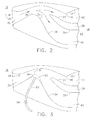
- FIG. 2 is an enlarged cross-sectional view of a portion of gas turbine engine inlet 16.
- Inlet 16 may be integral with engine 14 or may be separate from engine 14.
- inlet 16 functions as an inertial particle separator (IPS) and includes an entry channel 30 defined by an outer surface 32 and an inner surface 34.
- Inner surface 34 includes a convex section 36.
- a splitter 38 bifurcates entry channel 30 into a clean-fluid channel 40 and a dirty-fluid channel 42.
- Clean fluid channel 40 is defined by a lower surface 39 of splitter 38 and inner surface 34. Clean fluid channel 40 extends from inner surface convex section 36 to a compressor 44 included within the gas turbine engine 14.
- Dirty fluid channel 42 is defined by an upper surface 37 of splitter 38 and outer surface 32 and extends from convex section 36 to an IPS scavenge system (not shown).
- the IPS scavenge system is powered by a blower or an exhaust ejector. It should be appreciated that the term "fluid” as used herein includes any material or medium that flows, including but not limited to, gas, air and liquids.
- Figure 3 is an enlarged cross-sectional view of a portion of an exemplary gas turbine engine inlet 16.
- an inflatable flow path boot 50 that may be used with gas turbine engine 14 is coupled to the convex section 36 of inner surface 34 and a sensor 48 is coupled to outer surface 32.
- the inflatable flow path boot 50 may have any geometric configuration that enables inlet 16 to function as described herein.
- flow path boot 50 may be made from any material capable of withstanding the harsh operating environment of gas turbine engine inlet 16.
- inflatable flow path boot 50 is deployed using bleed air channeled from gas turbine engine 14.
- a duct 52 extends between boot 50 and a low pressure fluid source, such as but not limited to, the low pressure compressor 44.
- a control valve 54 facilitates controlling fluid flow from the low pressure source to flow path boot 50.
- inflatable flow path boot 50 is secured to inner surface 34 and is deployable from a non-inflated operating state to an inflated operating state.
- flow path boot 50 remains deflated and in its non-inflated state. In the non-inflated state, flow path boot 50 is substantially flush against inner surface 34 within convex section 36.
- flow path boot 50 is inflated such that the geometry of entry flow channel 30 and clean fluid channel 40 are changed.
- the inflated flow path boot 50 effectively reshapes the convex section 36 of the inner surface 34 and narrows the throat area by forcing the top surface 51 of boot 50 towards inlet outer surface 32. In doing so, top surface 51 of boot 50 reduces the width of the entry channel 30 and causes a sharper flow path turn to be defined at a trailing edge 35 of convex section 36. Moreover, inflated boot 50 creates a sharper turn for the fluid side that most of the sand and dust particles will not be capable of undergoing due to the inertia of such particles. Consequently, a higher percentage of sand and dust particles will be channeled into the dirty fluid channel 42, such that sand and dust separation efficiency is facilitated to be enhanced.
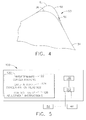
- Figure 4 is an enlarged view of convex section 36 and includes an inflated flow path boot 50 extending therefrom.
- Flow path boot 50 includes a plurality of fluid exit slots 56.
- the fluid exit slots 56 facilitate returning energy into a fluid boundary layer flowing past boot 50. As such, clean fluid flow adheres more closely to a top surface 51 of flow path boot 50 and is more able to make the sharp turn at the trailing edge 53 of the convex section defined by the top surface 51 and into clean fluid channel 40.
- fluid exit slots 56 may have any geometric shape that enables boot 50 to function as described herein, such as, but not limited to a cut in the boot 50, a rectangular opening, and/or a series of circular openings. Moreover, any number of slots 56 may be provided that enables boot 50 to function as described herein.
- Sensor 48 senses the concentration of sand and dust in entry channel 30.
- Sensor 48 may be, but is not limited to being, a side optical device and/or a "sand sniffer" in combination with a particle analyzer. It should be appreciated that sensor 48 may be any device that facilitates determining concentrations of sand and dust in gas turbine engine inlet 16. It should also be appreciated that although this exemplary embodiment is described using a single sensor 48 disposed in the front area of inlet 16 on outer surface 32, in various other exemplary embodiments sensor 48 may be installed on any surface or any other location that enables the fluid flow within inlet 16 to be analyzed as described herein.
- Sensor 48 communicates with a controller 100 by sending electrical signals representative of sand and dust concentrations to an input/output circuit 110.
- FIG. 5 is a block diagram illustrating an exemplary control logic and system controller 100 for use in determining when boot 50 should be deployed.
- the controller 100 includes an input/output circuit 110, a memory 120 and a processing circuit 130.
- the controller 100 communicates with sensor 48 and with control valve 54.
- processors may include any programmable system including systems using microcontrollers, reduced instruction set circuits (RISC), application specific integrated circuits (ASICs), logic circuits, and any other circuit or processor capable of executing the functions described herein.
- RISC reduced instruction set circuits
- ASICs application specific integrated circuits
- logic circuits and any other circuit or processor capable of executing the functions described herein.
- the above examples are exemplary only, and are thus not intended to limit in any way the definition and/or meaning of the term "processor”.
- the input/output interface circuit 110 receives signals transmitted to controller 100 from sand monitoring sources, such as sensor 48.
- controller 100 receives electrical signals from the sensor 48 that represent the concentration of sand and dust in the fluid. Additionally, input/output interface circuit 110 outputs signals produced by controller 100.
- the memory 120 can include one or more of a predetermined concentration portion 122, a sand and dust concentration readings portion 124, and/or a control valve adjustment instructions portion 126.
- the predetermined concentration portion 122 stores a predetermined value for the concentration of sand and dust in the fluid.
- Portion 124 stores sensor 48 readings taken during operation of gas turbine engine 14, and portion 126 stores instructions for opening and closing control valve 54.
- Memory 120 can be implemented using any appropriate combination of alterable, volatile or non-volatile memory or non-alterable, or fixed, memory.
- the alterable memory whether volatile or non-volatile, can be implemented using any one or more of static or dynamic RAM (Random Access Memory), a floppy disk and disk drive, a writeable or re-writeable optical disk and disk drive, a hard drive, flash memory or the like.
- non-alterable or fixed memory can be implemented using any one or more of ROM (Read-Only Memory), PROM (Programmable Read-Only Memory), EPROM (Erasable Programmable Read-Only Memory), EEPROM (Electrically Erasable Programmable Read-Only Memory), an optical ROM disk, such as a CD-ROM or DVD-ROM disk, and disk drive or the like.
- ROM Read-Only Memory
- PROM PROM
- EPROM Erasable Programmable Read-Only Memory
- EEPROM Electrical Erasable Programmable Read-Only Memory
- an optical ROM disk such as a CD-ROM or DVD-ROM disk, and disk drive or the like.
- processing circuit 130 compares each sand and dust concentration reading 124 with the predetermined concentration of sand and dust stored in the predetermined concentration portion 122.
- the predetermined concentration represents a threshold value that the sand and dust concentration should not equal or exceed.
- FIG. 6 is a flowchart illustrating an exemplary method for determining when inflatable flow path boot 50 (shown in Figures 3 and 4) should be deployed.
- a set of predetermined concentrations is defined at 72.
- sensor 48 generates a concentration reading corresponding to the amount of sand and dust in the fluid flowing in entry channel 30 (shown in Figure 3).
- the concentration reading from step 74 is compared at 76 against the predetermined concentration to determine whether the concentration reading is less than the predetermined concentration.
- the concentration reading is less than the predetermined concentration, operation proceeds to step 78. Otherwise, operation proceeds to step 86.
- the following discussion describes operation proceeding to step 78, then describes operation proceeding to step 86.
- step 78 a decision is made regarding whether the flow path boot 50 is inflated. If boot 50 is not inflated, operation proceeds to step 80 where a decision is made regarding whether additional sand and dust concentration readings are warranted. If additional readings are warranted, operation continues to step 74. If no additional readings are warranted, operation continues to step 88 wherein operation ends. At step 78, if boot 50 is inflated, operation proceeds to step 82.
- a signal is sent from the input/output circuit 110 to control valve 54.
- the signal instructs control valve 54 to close. Accordingly, fluid stops flowing to flow path boot 50 causing boot 50 to deflate. Operation then proceeds to step 84.
- a decision is made regarding whether additional sand and dust concentration readings are warranted. If additional readings are warranted, operation continues to step 74. If no additional readings are warranted, operation continues to step 88 wherein operation ends.
- step 76 when the concentration reading is not less than the predetermined concentration, operation proceeds to step 86.
- step 86 a signal is sent from the input/output circuit 110 to control valve 54. The signal instructs control valve 54 to open. Accordingly, fluid flows to flow path boot 50 causing boot 50 to inflate. Operation then proceeds to step 84.
- step 84 a decision is made regarding whether additional sand and dust concentration readings are warranted. If additional readings are warranted, operation continues to step 74. If no additional readings are warranted, operation continues to step 88 wherein operation ends.
- this exemplary embodiment enables craft to operate more efficiently when free of sand and dust conditions, versus operating with boot 50 constantly deployed.
- FIG 7 is a flowchart illustrating another exemplary method for determining when inflatable flow path boot 50 (shown in Figures 3 and 4) should be deployed.
- an aircraft operator or pilot, detects sand and dust conditions at 90.
- the operator uses an activator (not shown) to open control valve 54, such that fluid flows to flow path boot 50 causing boot 50 to inflate.
- the activator may be any kind of activator that enables control valve 54 to function as described herein.
- operation proceeds to step 94.
- step 94 the aircraft operator uses the activator (not shown) to close control valve 54, such that fluid ceases to flow to control path boot 50 causing boot 50 to deflate.
- this exemplary embodiment also enables craft to operate more efficiently when free of sand and dust conditions, versus operating with boot 50 constantly deployed.
- the exemplary embodiments described herein use the available space around the nose gearbox of a gas turbine engine 14 to cause fluid entering the inlet to turn abruptly through a two dimensional inertial particle separator before transitioning into the gas turbine engine 14 itself.
- the system could replace the aircraft inlet duct and EAPs system and is substantially more compact and lighter.
- an inflatable flow path boot 50 powered by low pressure engine bleed fluid.
- the bleed fluid may be controlled automatically using the controller 100 or, alternatively, may be controlled by aircraft operator action.
- the flow path boot 50 creates a sharper turn for the fluid, which facilitates enhancing higher sand separation efficiency.
- Aerodynamically designed fluid exit slots 56 are provided in boot 50 to facilitate delaying or preventing flow separation of the fluid in the flow path from inner surface 34, despite the sharp turning angle of the fluid at the trailing edge 53 of the convex section defined by the top surface 51.
- the combination of the flow path boot 50 and the fluid exit slots 56 offers a significant reliability advantage over conventional inertial particle separators.
- the fluid flow path only follows the aggressive turning configuration at the trailing edge 53 of the convex portion defined by the top surface 51 if there is fluid available to inflate boot 50 and to blow the boundary layer control fluid. Additionally, should the control valve 54 supplying fluid to the boot 50 malfunction, there is no risk of the inlet separating and causing an engine operability issue.
- the above-described inflatable boot with blowing slots facilitates sand and dust removal from the clean fluid entering the engine. More specifically, in each embodiment, the inflated boot creates a sharper turn that most sand and dust particles will not be capable of undergoing due to the inertia of such particles. As a result, during engine operation fewer sand and dust particles enter the engine. Accordingly, engine performance and component useful life are each facilitated to be enhanced in a cost effective and reliable manner. Moreover, various embodiments of the invention provide a means wherein existing inertial particle separators can be modified to facilitate enhancing turbine engine performance.
- inertial particle separators Exemplary embodiments of inertial particle separators are described above in detail.
- the inflatable boots are not limited to use with the specific inertial particles separator embodiments described herein, but rather, the inflatable boots can be utilized independently and separately from other inertial particle separator components described herein.
- the inflatable boots described herein may be retrofitted in most helicopter engines and may be used for a wide range of flow control scenarios, including aircraft control surfaces.
- the invention is not limited to the embodiments of the inflatable boots described above in detail. Rather, other variations of inflatable boot embodiments may be utilized within the spirit and scope of the claims.
Landscapes
- Engineering & Computer Science (AREA)
- Chemical & Material Sciences (AREA)
- Combustion & Propulsion (AREA)
- Mechanical Engineering (AREA)
- General Engineering & Computer Science (AREA)
- Physics & Mathematics (AREA)
- Geometry (AREA)
- Structures Of Non-Positive Displacement Pumps (AREA)
- Separating Particles In Gases By Inertia (AREA)
- Filtering Of Dispersed Particles In Gases (AREA)
Abstract
Description
- This invention relates generally to gas turbine engines, and more particularly, to adaptive inertial particle separators and methods of use.
- Sand and dust ingestion in gas turbine engines may adversely affect engine performance and reliability, and may also increase the frequency of repair and maintenance required for the engines. Because flight readiness depends at least partially on reliably and properly functioning engines, reducing the occurrence of, and/or the effects of, sand and dust ingestion should facilitate enhancing the reliability of the engines.
- Various methods are employed to facilitate reducing sand and dust concentrations channeled via the inlet airflow to the engine compressor. For example, known inertial particle separator (IPS) systems perform well in any weather conditions, are highly reliable, are integrated into the engine, but may not provide adequate separation efficiency during severe sand and dust conditions. Inertial inlet particle separators work by imparting momentum and trajectory on sand and dust particles to channel such particles away from the fluid stream entering the gas turbine engine. The particles removed are then collected or scavenged into an overboard dump. However, the same features that facilitate the separation of sand and dust particles from the inlet air, also cause inlet pressure losses that may detrimentally effect gas turbine engine performance. Because of the permanent nature of known IPS systems, engine performance loss is incurred in clean air and sandy air conditions.
- During operation, fluid flow into a gas turbine engine inlet is channeled downstream towards an entry channel. Downstream from a convex section, fluid flow is divided into two fluid streams. One of the streams, known as a dirty fluid flow, is channeled towards a dirty fluid channel. Debris, such as birds, and particles of debris, such as snow and/or ice particles, flow through the dirty fluid channel and into the IPS scavenge system wherein the debris is ejected from gas turbine engine. The other fluid stream, known as a clean fluid flow, is channeled into a clean fluid channel. To facilitate "clean" flow into the clean fluid channel, the clean fluid flow is forced to make a sharp turn around a convex section. Most debris will not be capable of changing direction at the turn, due to the greater inertia and momentum of the debris particles. Consequently, most debris will be channeled into the dirty fluid channel, thus facilitating a flow of clean fluid into the gas turbine engine. IPS systems of this type facilitate removal of large sand particles and debris, but generally such IPS systems are not as effective in removing smaller particles or debris.
- Some known helicopters are fitted with bulky barrier filters to address severe sand conditions. Although such filters satisfactorily remove sand and dust from the air, known filters are heavy, detrimentally effect engine performance, require increased maintenance, and are unable to operate in icing conditions. Moreover, known filters also cause a pressure drop at the inlet of the gas turbine engine that also adversely affects engine performance. Furthermore, known filters may also be susceptible to plugging with sand and dust.
- In one aspect according to the present invention, a method for operating a gas turbine engine including a compressor is provided. The method includes defining a predetermined concentration, placing at least one sensor in an inlet of the gas turbine engine, detecting a sand and dust concentration value using the at least one sensor and deploying a boot to facilitate preventing particles from entering the compressor when the sand and dust concentration value equals or exceeds the predetermined concentration. The boot includes a plurality of fluid exit slots such that clean air is facilitated to be adhered to a flow path surface downstream from the boot.
- In another aspect, an inertial particle separation system for a gas turbine engine is disclosed. The system includes an inlet of the gas turbine engine and an inflatable boot coupled to a surface defining a flow path through the inlet. The boot includes a plurality of fluid exit slots configured to facilitate clean air to adhere to a flow path surface downstream from the boot. The system also includes means for causing the boot to be deployed.
- In yet another aspect, a dual mode inertial particle separation apparatus for a gas turbine engine is provided. The apparatus includes an inertial particle separator including an entry channel and a flow path, the inertial particle separator facilitates effective removal of sand particles and debris from fluid in the entry channel during a first mode of operation of the inertial particle separator. The apparatus also includes an inflatable boot coupled to a surface of the inertial particle separator and defining the flow path. The boot is inflated during a second mode of operation of the inertial particle separator to facilitate increasing removal efficiency of sand particles and debris from fluid in the entry channel.
- Various aspects and embodiments of the present invention will now be described in connection with the accompanying drawings, in which:
- Figure 1 is a plan view of a portion of an exemplary helicopter including two gas turbine engine assemblies;
- Figure 2 is an enlarged cross-sectional view of a portion of a known gas turbine engine inlet that may be used with the engine assemblies shown in figure 1;
- Figure 3 is an enlarged cross-sectional view of a portion of a gas turbine engine inlet that may be used with the engine assembly shown in Figure 2, and includes an inflatable flow path boot;
- Figure 4 is an enlarged view of a portion of the inlet shown in Figure 2 and includes a deployed inflatable flow path boot;
- Figure 5 is a block diagram illustrating exemplary control logic for use with the inlet shown in Figures 2 and 3; and
- Figure 6 is a flowchart illustrating an exemplary method for determining when to deploy the inflatable flow path boot shown in Figures 3 and 4.
- Figure 7 is a flowchart illustrating another exemplary method for determining when to deploy the inflatable flow path boot shown in Figures 3 and 4.
- Figure 1 is a plan view of a portion of an
exemplary helicopter 10 that includes two gasturbine engine assemblies 12. Each gasturbine engine assembly 12 includes a pair ofgas turbine engines 14, each of which includes aninlet 16 and anexhaust 18. Thegas turbine engines 14 are oriented symmetrically with respect to an axis ofsymmetry 20 extending axially between thegas turbine engines 14. Moreover,gas turbine engines 14 are mounted within anengine compartment 22 defined by ahelicopter fuselage 24. Arear drive shaft 26 extends from eachgas turbine engine 14 to amain transmission 28. In other designs, driveshaft 26 may extend out of the front of eachengine 14. - Figure 2 is an enlarged cross-sectional view of a portion of gas
turbine engine inlet 16.Inlet 16 may be integral withengine 14 or may be separate fromengine 14. In the exemplary embodiment, inlet 16 functions as an inertial particle separator (IPS) and includes anentry channel 30 defined by anouter surface 32 and aninner surface 34.Inner surface 34 includes a convexsection 36. Asplitter 38bifurcates entry channel 30 into a clean-fluid channel 40 and a dirty-fluid channel 42.Clean fluid channel 40 is defined by alower surface 39 ofsplitter 38 andinner surface 34.Clean fluid channel 40 extends from innersurface convex section 36 to acompressor 44 included within thegas turbine engine 14.Dirty fluid channel 42 is defined by anupper surface 37 ofsplitter 38 andouter surface 32 and extends fromconvex section 36 to an IPS scavenge system (not shown). The IPS scavenge system is powered by a blower or an exhaust ejector. It should be appreciated that the term "fluid" as used herein includes any material or medium that flows, including but not limited to, gas, air and liquids. - Figure 3 is an enlarged cross-sectional view of a portion of an exemplary gas
turbine engine inlet 16. In the exemplary embodiment, an inflatableflow path boot 50 that may be used withgas turbine engine 14 is coupled to theconvex section 36 ofinner surface 34 and asensor 48 is coupled toouter surface 32. The inflatableflow path boot 50 may have any geometric configuration that enablesinlet 16 to function as described herein. Furthermore,flow path boot 50 may be made from any material capable of withstanding the harsh operating environment of gasturbine engine inlet 16. - In the exemplary embodiment, inflatable
flow path boot 50 is deployed using bleed air channeled fromgas turbine engine 14. Specifically, aduct 52 extends betweenboot 50 and a low pressure fluid source, such as but not limited to, thelow pressure compressor 44. Acontrol valve 54 facilitates controlling fluid flow from the low pressure source toflow path boot 50. - In the exemplary embodiment, inflatable
flow path boot 50 is secured toinner surface 34 and is deployable from a non-inflated operating state to an inflated operating state. During operation ofgas turbine engine 14, when sand and dust, for example, are not being drawn intoinlet 16,flow path boot 50 remains deflated and in its non-inflated state. In the non-inflated state, flowpath boot 50 is substantially flush againstinner surface 34 withinconvex section 36. However, when an unacceptable concentration of sand and dust is encountered or sensed enteringinlet 16,flow path boot 50 is inflated such that the geometry ofentry flow channel 30 andclean fluid channel 40 are changed. Specifically, the inflatedflow path boot 50 effectively reshapes theconvex section 36 of theinner surface 34 and narrows the throat area by forcing thetop surface 51 ofboot 50 towards inletouter surface 32. In doing so,top surface 51 ofboot 50 reduces the width of theentry channel 30 and causes a sharper flow path turn to be defined at a trailingedge 35 ofconvex section 36. Moreover, inflatedboot 50 creates a sharper turn for the fluid side that most of the sand and dust particles will not be capable of undergoing due to the inertia of such particles. Consequently, a higher percentage of sand and dust particles will be channeled into thedirty fluid channel 42, such that sand and dust separation efficiency is facilitated to be enhanced. - Figure 4 is an enlarged view of
convex section 36 and includes an inflatedflow path boot 50 extending therefrom. Flowpath boot 50 includes a plurality offluid exit slots 56. Thefluid exit slots 56 facilitate returning energy into a fluid boundary layer flowingpast boot 50. As such, clean fluid flow adheres more closely to atop surface 51 offlow path boot 50 and is more able to make the sharp turn at the trailingedge 53 of the convex section defined by thetop surface 51 and intoclean fluid channel 40. - This feature allows the clean fluid flow to go around the sharper turn without separating from the
top surface 51 andinner surface 34, without causing high pressure drop and flow distortion tocompressor 44. It should be appreciated thatfluid exit slots 56 may have any geometric shape that enablesboot 50 to function as described herein, such as, but not limited to a cut in theboot 50, a rectangular opening, and/or a series of circular openings. Moreover, any number ofslots 56 may be provided that enablesboot 50 to function as described herein. -
Sensor 48 senses the concentration of sand and dust inentry channel 30.Sensor 48 may be, but is not limited to being, a side optical device and/or a "sand sniffer" in combination with a particle analyzer. It should be appreciated thatsensor 48 may be any device that facilitates determining concentrations of sand and dust in gasturbine engine inlet 16. It should also be appreciated that although this exemplary embodiment is described using asingle sensor 48 disposed in the front area ofinlet 16 onouter surface 32, in various otherexemplary embodiments sensor 48 may be installed on any surface or any other location that enables the fluid flow withininlet 16 to be analyzed as described herein. Moreover, it should be appreciated that although this exemplary embodiment is described as including only asingle sensor 48, a plurality ofsensors 48 may be used to determine the concentration of sand and dust inentry channel 30.Sensor 48 communicates with acontroller 100 by sending electrical signals representative of sand and dust concentrations to an input/output circuit 110. - Figure 5 is a block diagram illustrating an exemplary control logic and
system controller 100 for use in determining whenboot 50 should be deployed. In the exemplary embodiment, thecontroller 100 includes an input/output circuit 110, amemory 120 and aprocessing circuit 130. Thecontroller 100 communicates withsensor 48 and withcontrol valve 54. - It should be understood that each of the circuits shown in Figure 5 can be implemented as portions of a suitably programmed general purpose processor. As used herein, the term "processor" may include any programmable system including systems using microcontrollers, reduced instruction set circuits (RISC), application specific integrated circuits (ASICs), logic circuits, and any other circuit or processor capable of executing the functions described herein. The above examples are exemplary only, and are thus not intended to limit in any way the definition and/or meaning of the term "processor".
- The input/
output interface circuit 110 receives signals transmitted tocontroller 100 from sand monitoring sources, such assensor 48. In this exemplary embodiment,controller 100 receives electrical signals from thesensor 48 that represent the concentration of sand and dust in the fluid. Additionally, input/output interface circuit 110 outputs signals produced bycontroller 100. - The
memory 120 can include one or more of apredetermined concentration portion 122, a sand and dustconcentration readings portion 124, and/or a control valveadjustment instructions portion 126. Thepredetermined concentration portion 122 stores a predetermined value for the concentration of sand and dust in the fluid.Portion 124stores sensor 48 readings taken during operation ofgas turbine engine 14, andportion 126 stores instructions for opening andclosing control valve 54. -
Memory 120 can be implemented using any appropriate combination of alterable, volatile or non-volatile memory or non-alterable, or fixed, memory. The alterable memory, whether volatile or non-volatile, can be implemented using any one or more of static or dynamic RAM (Random Access Memory), a floppy disk and disk drive, a writeable or re-writeable optical disk and disk drive, a hard drive, flash memory or the like. Similarly, the non-alterable or fixed memory can be implemented using any one or more of ROM (Read-Only Memory), PROM (Programmable Read-Only Memory), EPROM (Erasable Programmable Read-Only Memory), EEPROM (Electrically Erasable Programmable Read-Only Memory), an optical ROM disk, such as a CD-ROM or DVD-ROM disk, and disk drive or the like. - In this exemplary embodiment,
processing circuit 130 compares each sand and dust concentration reading 124 with the predetermined concentration of sand and dust stored in thepredetermined concentration portion 122. The predetermined concentration represents a threshold value that the sand and dust concentration should not equal or exceed. - Figure 6 is a flowchart illustrating an exemplary method for determining when inflatable flow path boot 50 (shown in Figures 3 and 4) should be deployed. Initially, a set of predetermined concentrations is defined at 72. Then in
step 74,sensor 48 generates a concentration reading corresponding to the amount of sand and dust in the fluid flowing in entry channel 30 (shown in Figure 3). The concentration reading fromstep 74 is compared at 76 against the predetermined concentration to determine whether the concentration reading is less than the predetermined concentration. When the concentration reading is less than the predetermined concentration, operation proceeds to step 78. Otherwise, operation proceeds to step 86. The following discussion describes operation proceeding to step 78, then describes operation proceeding to step 86. - At
step 78, a decision is made regarding whether theflow path boot 50 is inflated. Ifboot 50 is not inflated, operation proceeds to step 80 where a decision is made regarding whether additional sand and dust concentration readings are warranted. If additional readings are warranted, operation continues to step 74. If no additional readings are warranted, operation continues to step 88 wherein operation ends. Atstep 78, ifboot 50 is inflated, operation proceeds to step 82. - At
step 82, a signal is sent from the input/output circuit 110 to controlvalve 54. The signal instructscontrol valve 54 to close. Accordingly, fluid stops flowing to flowpath boot 50 causingboot 50 to deflate. Operation then proceeds to step 84. Atstep 84, a decision is made regarding whether additional sand and dust concentration readings are warranted. If additional readings are warranted, operation continues to step 74. If no additional readings are warranted, operation continues to step 88 wherein operation ends. - At
step 76, when the concentration reading is not less than the predetermined concentration, operation proceeds to step 86. Atstep 86, a signal is sent from the input/output circuit 110 to controlvalve 54. The signal instructscontrol valve 54 to open. Accordingly, fluid flows to flowpath boot 50 causingboot 50 to inflate. Operation then proceeds to step 84. Atstep 84, a decision is made regarding whether additional sand and dust concentration readings are warranted. If additional readings are warranted, operation continues to step 74. If no additional readings are warranted, operation continues to step 88 wherein operation ends. Thus, this exemplary embodiment enables craft to operate more efficiently when free of sand and dust conditions, versus operating withboot 50 constantly deployed. - Figure 7 is a flowchart illustrating another exemplary method for determining when inflatable flow path boot 50 (shown in Figures 3 and 4) should be deployed. Initially, an aircraft operator, or pilot, detects sand and dust conditions at 90. Then in
step 92, the operator uses an activator (not shown) to opencontrol valve 54, such that fluid flows to flowpath boot 50 causingboot 50 to inflate. It should be appreciated that the activator may be any kind of activator that enablescontrol valve 54 to function as described herein. When the aircraft operator does not detect a sand and dust condition at 93, operation proceeds to step 94. Atstep 94, the aircraft operator uses the activator (not shown) to closecontrol valve 54, such that fluid ceases to flow to controlpath boot 50 causingboot 50 to deflate. Thus, this exemplary embodiment also enables craft to operate more efficiently when free of sand and dust conditions, versus operating withboot 50 constantly deployed. - The exemplary embodiments described herein use the available space around the nose gearbox of a
gas turbine engine 14 to cause fluid entering the inlet to turn abruptly through a two dimensional inertial particle separator before transitioning into thegas turbine engine 14 itself. For example, if applied to a CH53 aircraft, the system could replace the aircraft inlet duct and EAPs system and is substantially more compact and lighter. Also disclosed herein, as part of the system, is an inflatableflow path boot 50 powered by low pressure engine bleed fluid. The bleed fluid may be controlled automatically using thecontroller 100 or, alternatively, may be controlled by aircraft operator action. Using the bleed fluid, theflow path boot 50 creates a sharper turn for the fluid, which facilitates enhancing higher sand separation efficiency. Aerodynamically designedfluid exit slots 56 are provided inboot 50 to facilitate delaying or preventing flow separation of the fluid in the flow path frominner surface 34, despite the sharp turning angle of the fluid at the trailingedge 53 of the convex section defined by thetop surface 51. - The combination of the
flow path boot 50 and thefluid exit slots 56 offers a significant reliability advantage over conventional inertial particle separators. The fluid flow path only follows the aggressive turning configuration at the trailingedge 53 of the convex portion defined by thetop surface 51 if there is fluid available to inflateboot 50 and to blow the boundary layer control fluid. Additionally, should thecontrol valve 54 supplying fluid to theboot 50 malfunction, there is no risk of the inlet separating and causing an engine operability issue. - In each embodiment, the above-described inflatable boot with blowing slots facilitates sand and dust removal from the clean fluid entering the engine. More specifically, in each embodiment, the inflated boot creates a sharper turn that most sand and dust particles will not be capable of undergoing due to the inertia of such particles. As a result, during engine operation fewer sand and dust particles enter the engine. Accordingly, engine performance and component useful life are each facilitated to be enhanced in a cost effective and reliable manner. Moreover, various embodiments of the invention provide a means wherein existing inertial particle separators can be modified to facilitate enhancing turbine engine performance.
- Exemplary embodiments of inertial particle separators are described above in detail. The inflatable boots are not limited to use with the specific inertial particles separator embodiments described herein, but rather, the inflatable boots can be utilized independently and separately from other inertial particle separator components described herein. For example, the inflatable boots described herein may be retrofitted in most helicopter engines and may be used for a wide range of flow control scenarios, including aircraft control surfaces. Moreover, the invention is not limited to the embodiments of the inflatable boots described above in detail. Rather, other variations of inflatable boot embodiments may be utilized within the spirit and scope of the claims.
- While the invention has been described in terms of various specific embodiments, those skilled in the art will recognize that the invention can be practiced with modification within the spirit and scope of the claims.
Claims (10)
- An inertial particle separation system for a gas turbine engine (14), said system comprising:an inlet (16) of said gas turbine engine;an inflatable boot (50) coupled to a surface defining a flow path through said inlet, said boot comprising a plurality of fluid exit slots (56) configured to facilitate clean air to adhere to a flow path surface downstream from said boot (50); andmeans for causing said boot to be deployed.
- A system in accordance with Claim 1 wherein said means further comprises a pilot, said pilot detects a sand and dust condition and activates a control valve (54) to inflate said boot (50).
- A system in accordance with Claim 2 wherein said pilot detects a condition free of sand and dust and activates said control valve (54) to deflate said boot (50).
- A system in accordance with any preceding Claim further comprising:at least one sensor (48) coupled to said inlet (16), said at least one sensor configured to detect a concentration of particles in fluid flowing through said inlet; andwherein said means comprises a system controller (100), said system controller coupled to said at least one sensor to compare a sensed concentration value with a predetermined concentration stored in said controller, said controller configured to cause said boot (50) to be deployed when said sensed concentration value equals or exceeds said predetermined concentration (122).
- A system in accordance with Claim 4 wherein said inlet (16) includes an entry channel (30), said at least one sensor (48) is coupled to a surface (32) defining a flow path through said entry channel.
- A system in accordance with any preceding Claim wherein said inflatable boot (50) is deployed using bleed fluid.
- A system in accordance with any preceding Claim wherein said boot is configured to create a sharp turn for fluid entering a clean fluid channel (40).
- A system in accordance with any preceding Claim wherein each one of said plurality of fluid exit slots (56) is configured to inject energy into a boundary layer downstream from said boot (50).
- A system in accordance with any preceding Claim wherein said boot (50) is selectively inflated and deflated based on a concentration of particles in fluid entering the gas turbine engine (14).
- A dual mode particle inertial separation apparatus for a gas turbine engine (14), said apparatus comprising:an inertial particle separator comprising an entry channel (30) and a flow path, said inertial particle separator facilitating effective removal of sand particles and debris from fluid in said entry channel during a first mode of operation of said inertial particle separator; andan inflatable boot (50) coupled to a surface (34) of said inertial particle separator and defining said flow path, said boot (50) inflated during a second mode of operation of said inertial particle separator to facilitate increasing removal efficiency of sand particles and debris from fluid in said entry channel.
Applications Claiming Priority (1)
| Application Number | Priority Date | Filing Date | Title |
|---|---|---|---|
| US11/528,219 US7802433B2 (en) | 2006-09-27 | 2006-09-27 | Adaptive inertial particle separators and methods of use |
Publications (3)
| Publication Number | Publication Date |
|---|---|
| EP1908939A2 true EP1908939A2 (en) | 2008-04-09 |
| EP1908939A3 EP1908939A3 (en) | 2013-12-18 |
| EP1908939B1 EP1908939B1 (en) | 2016-03-30 |
Family
ID=39008215
Family Applications (1)
| Application Number | Title | Priority Date | Filing Date |
|---|---|---|---|
| EP07116220.0A Not-in-force EP1908939B1 (en) | 2006-09-27 | 2007-09-12 | Adaptive inertial particle separator |
Country Status (4)
| Country | Link |
|---|---|
| US (1) | US7802433B2 (en) |
| EP (1) | EP1908939B1 (en) |
| JP (1) | JP5121371B2 (en) |
| CA (1) | CA2601652C (en) |
Cited By (6)
| Publication number | Priority date | Publication date | Assignee | Title |
|---|---|---|---|---|
| GB2489475A (en) * | 2011-03-30 | 2012-10-03 | Rolls Royce Plc | Variable geometry duct |
| CN103174521A (en) * | 2011-12-21 | 2013-06-26 | 通用电气公司 | Gas turbine engine particle separator |
| EP2737933A1 (en) * | 2012-11-29 | 2014-06-04 | Honeywell International Inc. | Inlet particle separator system with air injection |
| US9376931B2 (en) | 2012-01-27 | 2016-06-28 | General Electric Company | Turbomachine passage cleaning system |
| CN107605602B (en) * | 2016-11-09 | 2018-08-31 | 南京航空航天大学 | A kind of structure changes turboshaft engine gas handling system |
| EP3536930A1 (en) * | 2018-03-07 | 2019-09-11 | Rolls-Royce North American Technologies, Inc. | Adaptive-curvature inertial particle separators |
Families Citing this family (33)
| Publication number | Priority date | Publication date | Assignee | Title |
|---|---|---|---|---|
| US7678165B2 (en) * | 2006-12-28 | 2010-03-16 | General Electric Company | Particle separator using boundary layer control |
| FR2914364B1 (en) * | 2007-03-30 | 2009-06-12 | Snecma Sa | FRONT TURBOMACHINE PART COMPRISING A FOREIGN BODY DEFLECTOR SYSTEM SUCH AS HAIL. |
| US7922784B2 (en) | 2009-03-23 | 2011-04-12 | King Fahd University Of Petroleum And Minerals | System for inertial particles separation |
| US20120105839A1 (en) * | 2009-07-11 | 2012-05-03 | Enertechnix, Inc | Progressive Cut-Size Particle Trap and Aerosol Collection Apparatus |
| US20110088652A1 (en) * | 2009-10-21 | 2011-04-21 | Rockenbach Frederick A | Ram induction system |
| US8475115B2 (en) * | 2010-06-02 | 2013-07-02 | General Electric Company | Pre-filtration bypass for gas turbine inlet filter house |
| US20120131900A1 (en) * | 2010-11-30 | 2012-05-31 | General Electric Company | Inlet particle separator system |
| US20160090912A1 (en) * | 2010-11-30 | 2016-03-31 | General Electric Company | Inlet particle separator system |
| US8452516B1 (en) | 2012-01-31 | 2013-05-28 | United Technologies Corporation | Variable vane scheduling based on flight conditions for inclement weather |
| US9314723B2 (en) | 2012-09-17 | 2016-04-19 | Honeywell International Inc. | Inlet particle separator systems and methods |
| US10184399B2 (en) | 2012-09-17 | 2019-01-22 | Honeywell International Inc. | Inlet particle separator systems and methods |
| US9206740B2 (en) * | 2013-01-04 | 2015-12-08 | Honeywell International Inc. | Liquid injection inlet particle separator systems and methods |
| US9638103B2 (en) * | 2013-07-26 | 2017-05-02 | Honeywell International Inc. | Plasma flow control inlet particle separator system |
| CA2859441C (en) | 2013-08-16 | 2021-10-12 | Eric Loth | Particle separator |
| US10668414B2 (en) | 2014-07-23 | 2020-06-02 | Cummins Filtration Ip, Inc. | Intake bypass flow management systems and methods |
| US20160177823A1 (en) * | 2014-12-22 | 2016-06-23 | General Electric Company | System and method with inlet particle separator |
| US10138904B2 (en) | 2016-01-06 | 2018-11-27 | Honeywell International Inc. | Inlet particle separator system with high curvature hub |
| US10208628B2 (en) | 2016-03-30 | 2019-02-19 | Honeywell International Inc. | Turbine engine designs for improved fine particle separation efficiency |
| US10393021B2 (en) | 2016-09-01 | 2019-08-27 | Rolls-Royce North American Technologies Inc. | Particle separator |
| US20180135516A1 (en) | 2016-11-16 | 2018-05-17 | Honeywell International Inc. | Scavenge methodologies for turbine engine particle separation concepts |
| US10888881B2 (en) | 2017-05-08 | 2021-01-12 | Cummins Filtration Ip, Inc. | Variable inertial particle separator |
| US10738699B2 (en) | 2018-01-19 | 2020-08-11 | Rolls-Royce North American Technologies Inc. | Air-inlet particle separator having a bleed surface |
| US10816014B2 (en) | 2018-07-25 | 2020-10-27 | Honeywell International Inc. | Systems and methods for turbine engine particle separation |
| US11261800B2 (en) | 2018-10-24 | 2022-03-01 | Raytheon Technologies Corporation | Adaptive bleed schedule in a gas turbine engine |
| US11125168B2 (en) | 2018-10-24 | 2021-09-21 | Raytheon Technologies Corporation | Dirt mitigation in a gas turbine engine |
| CN113950576A (en) | 2019-03-29 | 2022-01-18 | 唐纳森公司 | Air cleaner bypass assembly and method of operation |
| US11149638B2 (en) | 2019-04-22 | 2021-10-19 | Rolls-Royce Corporation | Particle separator |
| US11713722B2 (en) * | 2020-05-08 | 2023-08-01 | Rolls-Royce Corporation | Gas turbine engine compressor particulate offtake |
| US11499478B2 (en) | 2020-11-19 | 2022-11-15 | Honeywell International Inc. | Asymmetric inlet particle separator for gas turbine engine |
| US11692481B1 (en) * | 2022-04-29 | 2023-07-04 | Pratt & Whitney Canada Corp. | Inertial particle separator duct assembly with splitter |
| EP4292941A1 (en) * | 2022-06-15 | 2023-12-20 | Zero Emissions Aerospace Limited | Aircraft fuel cell air supply anti contamination system |
| US11834988B1 (en) | 2022-06-15 | 2023-12-05 | Rolls-Royce North American Technologies Inc. | Turbine engine inertial particle separator with particle rebound suppression |
| US11965460B1 (en) | 2022-10-31 | 2024-04-23 | Pratt & Whitney Canada Corp. | Systems and methods for controlling an air flow path for a propulsion system air intake |
Family Cites Families (26)
| Publication number | Priority date | Publication date | Assignee | Title |
|---|---|---|---|---|
| US2944731A (en) * | 1956-05-17 | 1960-07-12 | Lockheed Aircraft Corp | Debris traps for engine-air inlets |
| US3371471A (en) * | 1965-10-15 | 1968-03-05 | Avco Corp | Sand and dust collector for engine air inlets |
| US3338049A (en) * | 1966-02-01 | 1967-08-29 | Gen Electric | Gas turbine engine including separator for removing extraneous matter |
| US3521431A (en) * | 1969-04-28 | 1970-07-21 | Avco Corp | Particle separator for engine air inlets |
| US3534548A (en) * | 1969-06-30 | 1970-10-20 | Avco Corp | Separator apparatus for engine air inlets |
| US3766719A (en) | 1971-11-26 | 1973-10-23 | United Aircraft Corp | Particle and moisture separator for engine inlet |
| US3733814A (en) | 1972-02-22 | 1973-05-22 | Gen Electric | Translatable engine inlet particle separator |
| US3952972A (en) * | 1974-12-24 | 1976-04-27 | United Aircraft Of Canada Limited | Inertial separator |
| US4098594A (en) | 1976-12-13 | 1978-07-04 | Textron Inc. | Inertial particle separator |
| CA1116418A (en) * | 1979-07-18 | 1982-01-19 | Pratt & Whitney Aircraft Of Canada Limited | Vane fairing for inertial separator |
| GB2069053B (en) * | 1980-02-09 | 1983-04-13 | Rolls Royce | Water separator in gas turbine inlet |
| US4406433A (en) * | 1980-12-18 | 1983-09-27 | Aerovironment, Inc. | Leading edge inlet for ram air pressurized airfoil |
| GB2095335B (en) * | 1981-03-20 | 1984-05-31 | Rolls Royce | Gas turbine engine air intake system |
| US4509962A (en) | 1983-10-06 | 1985-04-09 | Pratt & Whitney Canada Inc. | Inertial particle separator |
| US4617028A (en) * | 1983-11-03 | 1986-10-14 | General Electric Company | Aircraft engine air intake including a foreign object separator |
| US4928480A (en) * | 1988-03-04 | 1990-05-29 | General Electric Company | Separator having multiple particle extraction passageways |
| US5039317A (en) | 1990-07-05 | 1991-08-13 | Allied-Signal Inc. | Radial inflow particle separation method and apparatus |
| US6134874A (en) | 1998-06-02 | 2000-10-24 | Pratt & Whitney Canada Corp. | Integral inertial particle separator for radial inlet gas turbine engine |
| US6390418B1 (en) * | 1999-02-25 | 2002-05-21 | United Technologies Corporation | Tangentially directed acoustic jet controlling boundary layer |
| JP2000303858A (en) * | 1999-04-23 | 2000-10-31 | Ishikawajima Harima Heavy Ind Co Ltd | Duct boundary layer control device |
| US6508052B1 (en) | 2001-08-01 | 2003-01-21 | Rolls-Royce Corporation | Particle separator |
| US6499285B1 (en) | 2001-08-01 | 2002-12-31 | Rolls-Royce Corporation | Particle separator for a gas turbine engine |
| US6698180B2 (en) | 2001-08-01 | 2004-03-02 | Rolls-Royce Corporation | Particle separator for a turbine engine |
| US6702873B2 (en) * | 2002-04-23 | 2004-03-09 | The Boeing Company | High particle separation efficiency system |
| US6755897B2 (en) | 2002-10-23 | 2004-06-29 | Siemens Vdo Automotive Inc. | Constant velocity radial inflow particle separator |
| US7678165B2 (en) * | 2006-12-28 | 2010-03-16 | General Electric Company | Particle separator using boundary layer control |
-
2006
- 2006-09-27 US US11/528,219 patent/US7802433B2/en active Active
-
2007
- 2007-09-12 EP EP07116220.0A patent/EP1908939B1/en not_active Not-in-force
- 2007-09-13 CA CA2601652A patent/CA2601652C/en not_active Expired - Fee Related
- 2007-09-26 JP JP2007249207A patent/JP5121371B2/en not_active Expired - Fee Related
Cited By (8)
| Publication number | Priority date | Publication date | Assignee | Title |
|---|---|---|---|---|
| GB2489475A (en) * | 2011-03-30 | 2012-10-03 | Rolls Royce Plc | Variable geometry duct |
| CN103174521A (en) * | 2011-12-21 | 2013-06-26 | 通用电气公司 | Gas turbine engine particle separator |
| CN103174521B (en) * | 2011-12-21 | 2016-12-21 | 通用电气公司 | Gas-turbine unit particle separator |
| US9376931B2 (en) | 2012-01-27 | 2016-06-28 | General Electric Company | Turbomachine passage cleaning system |
| EP2737933A1 (en) * | 2012-11-29 | 2014-06-04 | Honeywell International Inc. | Inlet particle separator system with air injection |
| CN107605602B (en) * | 2016-11-09 | 2018-08-31 | 南京航空航天大学 | A kind of structure changes turboshaft engine gas handling system |
| EP3536930A1 (en) * | 2018-03-07 | 2019-09-11 | Rolls-Royce North American Technologies, Inc. | Adaptive-curvature inertial particle separators |
| US10767558B2 (en) | 2018-03-07 | 2020-09-08 | Rolls-Royce North American Technologies Inc. | Adaptive-curvature inertial particle separators |
Also Published As
| Publication number | Publication date |
|---|---|
| EP1908939A3 (en) | 2013-12-18 |
| US20080072606A1 (en) | 2008-03-27 |
| CA2601652A1 (en) | 2008-03-27 |
| JP5121371B2 (en) | 2013-01-16 |
| EP1908939B1 (en) | 2016-03-30 |
| CA2601652C (en) | 2015-03-10 |
| US7802433B2 (en) | 2010-09-28 |
| JP2008088977A (en) | 2008-04-17 |
Similar Documents
| Publication | Publication Date | Title |
|---|---|---|
| EP1908939B1 (en) | Adaptive inertial particle separator | |
| EP1978222B1 (en) | Particle separator and debris control system | |
| JP5738772B2 (en) | Apparatus and method for passive purging of micro-perforated aerodynamic surfaces | |
| EP1942258B1 (en) | Particle separator using boundary layer control | |
| CN103269952B (en) | Aerocraft black box | |
| EP1510659B1 (en) | Gas turbine engine comprising a vane assembly in a cooling air flowpath and method for removing particles from a cooling airflow | |
| US4106730A (en) | Engine out control system for STOL aircraft | |
| US5123240A (en) | Method and apparatus for ejecting foreign matter from the primary flow path of a gas turbine engine | |
| EP3260687A1 (en) | Inlet particle separator system with pre-cleaner flow passage | |
| JP6205107B2 (en) | Inlet particle separation system | |
| WO2007116621A1 (en) | Axial flow fluid device and blade | |
| US20180119640A1 (en) | Fan nacelle trailing edge | |
| CA2915142A1 (en) | System and method with inlet particle separator | |
| JPH0321730B2 (en) | ||
| US8539748B2 (en) | Segmented inertial particle separators and methods of assembling turbine engines | |
| EP3118459B1 (en) | Ram air fan assembly with surge detection | |
| JP2007022268A (en) | Flying machine control device | |
| CN110844091A (en) | Injection type engine sand prevention system and method | |
| RU2347093C2 (en) | Method for control of bypass two-shaft gas turbine engine of airplane and device for its realisation | |
| US11993390B2 (en) | System and method for air filtration with self-cleaning filter medium for an aircraft engine | |
| US20100258655A1 (en) | Ram air outlet duct | |
| GB2257752A (en) | Gas turbine inlet particle separator. | |
| JPH04201694A (en) | Spanwise blowing device for aircraft |
Legal Events
| Date | Code | Title | Description |
|---|---|---|---|
| PUAI | Public reference made under article 153(3) epc to a published international application that has entered the european phase |
Free format text: ORIGINAL CODE: 0009012 |
|
| AK | Designated contracting states |
Kind code of ref document: A2 Designated state(s): AT BE BG CH CY CZ DE DK EE ES FI FR GB GR HU IE IS IT LI LT LU LV MC MT NL PL PT RO SE SI SK TR |
|
| AX | Request for extension of the european patent |
Extension state: AL BA HR MK RS |
|
| PUAL | Search report despatched |
Free format text: ORIGINAL CODE: 0009013 |
|
| AK | Designated contracting states |
Kind code of ref document: A3 Designated state(s): AT BE BG CH CY CZ DE DK EE ES FI FR GB GR HU IE IS IT LI LT LU LV MC MT NL PL PT RO SE SI SK TR |
|
| AX | Request for extension of the european patent |
Extension state: AL BA HR MK RS |
|
| RIC1 | Information provided on ipc code assigned before grant |
Ipc: F02C 7/05 20060101AFI20131108BHEP Ipc: F02C 7/042 20060101ALI20131108BHEP |
|
| 17P | Request for examination filed |
Effective date: 20140618 |
|
| RBV | Designated contracting states (corrected) |
Designated state(s): AT BE BG CH CY CZ DE DK EE ES FI FR GB GR HU IE IS IT LI LT LU LV MC MT NL PL PT RO SE SI SK TR |
|
| AKX | Designation fees paid |
Designated state(s): DE FR GB IT SE |
|
| 17Q | First examination report despatched |
Effective date: 20150206 |
|
| GRAP | Despatch of communication of intention to grant a patent |
Free format text: ORIGINAL CODE: EPIDOSNIGR1 |
|
| INTG | Intention to grant announced |
Effective date: 20151106 |
|
| GRAS | Grant fee paid |
Free format text: ORIGINAL CODE: EPIDOSNIGR3 |
|
| GRAA | (expected) grant |
Free format text: ORIGINAL CODE: 0009210 |
|
| AK | Designated contracting states |
Kind code of ref document: B1 Designated state(s): DE FR GB IT SE |
|
| REG | Reference to a national code |
Ref country code: GB Ref legal event code: FG4D |
|
| REG | Reference to a national code |
Ref country code: DE Ref legal event code: R096 Ref document number: 602007045511 Country of ref document: DE |
|
| REG | Reference to a national code |
Ref country code: SE Ref legal event code: TRGR |
|
| REG | Reference to a national code |
Ref country code: FR Ref legal event code: PLFP Year of fee payment: 10 |
|
| PGFP | Annual fee paid to national office [announced via postgrant information from national office to epo] |
Ref country code: GB Payment date: 20160927 Year of fee payment: 10 |
|
| REG | Reference to a national code |
Ref country code: DE Ref legal event code: R097 Ref document number: 602007045511 Country of ref document: DE |
|
| PLBE | No opposition filed within time limit |
Free format text: ORIGINAL CODE: 0009261 |
|
| STAA | Information on the status of an ep patent application or granted ep patent |
Free format text: STATUS: NO OPPOSITION FILED WITHIN TIME LIMIT |
|
| 26N | No opposition filed |
Effective date: 20170103 |
|
| REG | Reference to a national code |
Ref country code: FR Ref legal event code: PLFP Year of fee payment: 11 |
|
| PGFP | Annual fee paid to national office [announced via postgrant information from national office to epo] |
Ref country code: IT Payment date: 20170925 Year of fee payment: 11 Ref country code: FR Payment date: 20170925 Year of fee payment: 11 |
|
| PGFP | Annual fee paid to national office [announced via postgrant information from national office to epo] |
Ref country code: SE Payment date: 20170927 Year of fee payment: 11 |
|
| PGFP | Annual fee paid to national office [announced via postgrant information from national office to epo] |
Ref country code: DE Payment date: 20170927 Year of fee payment: 11 |
|
| GBPC | Gb: european patent ceased through non-payment of renewal fee |
Effective date: 20170912 |
|
| PG25 | Lapsed in a contracting state [announced via postgrant information from national office to epo] |
Ref country code: GB Free format text: LAPSE BECAUSE OF NON-PAYMENT OF DUE FEES Effective date: 20170912 |
|
| REG | Reference to a national code |
Ref country code: DE Ref legal event code: R119 Ref document number: 602007045511 Country of ref document: DE |
|
| REG | Reference to a national code |
Ref country code: SE Ref legal event code: EUG |
|
| PG25 | Lapsed in a contracting state [announced via postgrant information from national office to epo] |
Ref country code: SE Free format text: LAPSE BECAUSE OF NON-PAYMENT OF DUE FEES Effective date: 20180913 |
|
| PG25 | Lapsed in a contracting state [announced via postgrant information from national office to epo] |
Ref country code: DE Free format text: LAPSE BECAUSE OF NON-PAYMENT OF DUE FEES Effective date: 20190402 Ref country code: IT Free format text: LAPSE BECAUSE OF NON-PAYMENT OF DUE FEES Effective date: 20180912 |
|
| PG25 | Lapsed in a contracting state [announced via postgrant information from national office to epo] |
Ref country code: FR Free format text: LAPSE BECAUSE OF NON-PAYMENT OF DUE FEES Effective date: 20180930 |