EP1908903A1 - Door checker for automobile - Google Patents
Door checker for automobile Download PDFInfo
- Publication number
- EP1908903A1 EP1908903A1 EP06781066A EP06781066A EP1908903A1 EP 1908903 A1 EP1908903 A1 EP 1908903A1 EP 06781066 A EP06781066 A EP 06781066A EP 06781066 A EP06781066 A EP 06781066A EP 1908903 A1 EP1908903 A1 EP 1908903A1
- Authority
- EP
- European Patent Office
- Prior art keywords
- face
- resilient member
- detent
- case
- resilient
- Prior art date
- Legal status (The legal status is an assumption and is not a legal conclusion. Google has not performed a legal analysis and makes no representation as to the accuracy of the status listed.)
- Granted
Links
Images



Classifications
-
- E—FIXED CONSTRUCTIONS
- E05—LOCKS; KEYS; WINDOW OR DOOR FITTINGS; SAFES
- E05C—BOLTS OR FASTENING DEVICES FOR WINGS, SPECIALLY FOR DOORS OR WINDOWS
- E05C17/00—Devices for holding wings open; Devices for limiting opening of wings or for holding wings open by a movable member extending between frame and wing; Braking devices, stops or buffers, combined therewith
- E05C17/02—Devices for holding wings open; Devices for limiting opening of wings or for holding wings open by a movable member extending between frame and wing; Braking devices, stops or buffers, combined therewith by mechanical means
- E05C17/04—Devices for holding wings open; Devices for limiting opening of wings or for holding wings open by a movable member extending between frame and wing; Braking devices, stops or buffers, combined therewith by mechanical means with a movable bar or equivalent member extending between frame and wing
- E05C17/12—Devices for holding wings open; Devices for limiting opening of wings or for holding wings open by a movable member extending between frame and wing; Braking devices, stops or buffers, combined therewith by mechanical means with a movable bar or equivalent member extending between frame and wing consisting of a single rod
- E05C17/20—Devices for holding wings open; Devices for limiting opening of wings or for holding wings open by a movable member extending between frame and wing; Braking devices, stops or buffers, combined therewith by mechanical means with a movable bar or equivalent member extending between frame and wing consisting of a single rod sliding through a guide
- E05C17/203—Devices for holding wings open; Devices for limiting opening of wings or for holding wings open by a movable member extending between frame and wing; Braking devices, stops or buffers, combined therewith by mechanical means with a movable bar or equivalent member extending between frame and wing consisting of a single rod sliding through a guide concealed, e.g. for vehicles
- E05C17/206—Devices for holding wings open; Devices for limiting opening of wings or for holding wings open by a movable member extending between frame and wing; Braking devices, stops or buffers, combined therewith by mechanical means with a movable bar or equivalent member extending between frame and wing consisting of a single rod sliding through a guide concealed, e.g. for vehicles with elastomeric springs to hold wing open
-
- E—FIXED CONSTRUCTIONS
- E05—LOCKS; KEYS; WINDOW OR DOOR FITTINGS; SAFES
- E05B—LOCKS; ACCESSORIES THEREFOR; HANDCUFFS
- E05B17/00—Accessories in connection with locks
- E05B17/002—Weather or dirt protection
Definitions
- an automobile door checker comprising a case secured to one of an automobile body and a door pivotably supported on the automobile body, a check plate that runs movably through the case and is coupled to the other one of the body and the door, a detent member slidably fitted into and retained by the case so as to retain the door at a predetermined open position in cooperation with a detent face of the check plate, and a resilient member that is made of a resilient material, is provided in a compressed state in a housing chamber defined between an outer end face of the detent member on a side opposite to the check plate and an inner end face of the case opposite the outer end face, and generates a detent force between the detent member and the detent face, characterized in that the resilient member is formed so as to substantially fill the housing chamber, the resilient member is provided with a hole portion that allows resilient deformation of the resilient member, the hole portion being sealed by the outer end face and the inner end face, and one half
- the door checker C has a case 1 secured to an inner face of an end wall of the door D.
- This case 1 is formed from a box-shaped case main body 1 a having one end open and a cover 1b joined to the case main body 1 a via swage portions 11 and 11 (see FIG. 4 ) while covering the open end, and the case main body 1 a and the cover 1 b are secured to the end wall of the door D by means of a pair of upper and lower bolts 2 and 2 so that the cover 1b abuts against the inner face of the end wall.
- housing chambers 18 and 18 are defined in the interior of the case 1 between outer end faces 18a of the detent members 16 and 16 on the side opposite to the check plate 6 and upper and lower inner end faces 18b of the case 1 facing the outer end faces 18a, and a pair of upper and lower resilient members 17 and 17 are fitted in a compressed state into the housing chambers 18 and 18, the resilient members 17 and 17 resiliently urging the detent members 16 and 16 against the detent faces 10 and 10 of the check plate 6.
- Each resilient member 17 is formed from a resilient material such as an elastomer so that the housing chamber 18 is substantially filled therewith and one half of the resilient member 17 on the outer end face 18a side of the detent member 16 and the other half on the inner end face 18b side of the case 1 are symmetrical. Furthermore, each resilient member 17 is formed so that a left half on the left inside face side of the case 1 and a right half on the right inside face side of the case 1 are symmetrical.
- the resilient member 17 is formed so that a half on the side in which it is in intimate contact with the outer end face 18a and the other half on the side in which it is intimate contact with the inner end face 18b are symmetrical and, furthermore, a left half on the left inside face side of the case 1 and a right half on the right inside face side of the case 1 are symmetrical, it is unnecessary to restrict the direction of the resilient member 17 with respect to the outer end face 18a and the inner end face 18b in either the vertical direction or the lateral direction when fitting the resilient member 17 into the housing chamber 18, the ease of assembly is good, and it is consequently possible to not only avoid misassembly but also for the proper function of the resilient member 17 to be always exhibited.
Landscapes
- Engineering & Computer Science (AREA)
- Mechanical Engineering (AREA)
- Seal Device For Vehicle (AREA)
- Specific Sealing Or Ventilating Devices For Doors And Windows (AREA)
- Body Structure For Vehicles (AREA)
- Vibration Dampers (AREA)
Abstract
Description
- The present invention relates to an improvement of an automobile door checker that includes a case secured to one of an automobile body and a door pivotably supported on the automobile body, a check plate that runs movably through the case and is coupled to the other one of the body and the door, a detent member slidably fitted into and retained by the case so as to retain the door at a predetermined open position in cooperation with a detent face of the check plate, and a resilient member that is made of a resilient material, is provided in a compressed state in a housing chamber defined between an outer end face of the detent member on a side opposite to the check plate and an inner end face of the case opposite this outer end face, and generates a detent force between the detent member and the detent face.
- Such a door checker is already known, as disclosed in Patent Publication 1. Patent Publication 1:
Japanese Patent Application Laid-open No. 9-256714 - In such a conventional automobile door checker, since a space for allowing the resilient member to resiliently deform is provided between an outer face of the resilient member and the inner face of the case, rainwater might infiltrate into this space by moving along the check plate, etc., and if the rainwater freezes, the resilient deformation characteristics of the resilient member change, thus causing an uncomfortable sensation when opening and closing the door.
- Accordingly, an arrangement is known in which the case or the check plate is covered by a waterproof cover to thus prevent rainwater from infiltrating into the case, but even in such an arrangement it is impossible to make the interior of the case completely watertight, the number of components increases, and the cost becomes high.
- The present invention has been accomplished in the light of such circumstances, and it is an object thereof to provide an automobile door checker of the above type that as far as possible prevents rainwater from infiltrating into a housing chamber for a resilient member and that, even if some rainwater that has infiltrated freezes, prevents the resilient deformation characteristics of the resilient member from changing, thus avoiding the occurrence of an uncomfortable sensation when opening and closing a door.
- In order to attain the above object, according to a first aspect of the present invention, there is provided an automobile door checker comprising a case secured to one of an automobile body and a door pivotably supported on the automobile body, a check plate that runs movably through the case and is coupled to the other one of the body and the door, a detent member slidably fitted into and retained by the case so as to retain the door at a predetermined open position in cooperation with a detent face of the check plate, and a resilient member that is made of a resilient material, is provided in a compressed state in a housing chamber defined between an outer end face of the detent member on a side opposite to the check plate and an inner end face of the case opposite the outer end face, and generates a detent force between the detent member and the detent face, characterized in that the resilient member is formed so as to substantially fill the housing chamber, the resilient member is provided with a hole portion that allows resilient deformation of the resilient member, the hole portion being sealed by the outer end face and the inner end face, and one half of the resilient member on the outer end face side and the other half on the inner end face side are symmetrical.
- Further, according to a second aspect of the present invention, in addition to the first aspect, the resilient member is provided with a dividing wall for dividing the hole portion into two portions that are blocked from each other.
- Moreover, according to a third aspect of the present invention, in addition to the first or second aspect, annular seal lips are formed on the outer face of the resilient member, the annular seal lips surrounding an open end of the hole portion and being in intimate contact with the outer end face or the inner end face.
- Furthermore, according to a fourth aspect of the present invention, in addition to any one of the first to third aspects, the hole portion is formed so as to have a circular cross-section.
- Furthermore, according to a fifth aspect of the present invention, in addition to the first aspect, a left half of the resilient member on a left inside face side of the case and a right half on a right inside face side of the case are symmetrical.
- In accordance with the first aspect of the present invention, since the resilient member can be formed so as to substantially fill the housing chamber within the case, it is possible to prevent as far as possible rainwater from infiltrating into the housing chamber.
- Moreover, since the resilient member is provided with the hole portion for allowing its resilient deformation so that the hole portion is sealed by the outer end face and the inner end face, even if some rainwater infiltrates into the housing chamber and freezes, resilient deformation of the resilient member is allowed as normal within the sealed hole portion, the resilient deformation characteristics of the resilient member therefore do not change, and the good opening and closing feel of the door can always be maintained.
- Furthermore, since the hole portion opens on the outer face of the resilient member, this can be easily formed using a mold when molding the resilient member.
- Moreover, since one half of the resilient member on the outer end face side and the other half thereof on the inner end face side are symmetrical, when fitting the resilient member into the housing chamber, it is unnecessary to restrict the direction of the resilient member with respect to the outer end face and the inner end face, the ease of assembly is good, and it is consequently possible to not only avoid misassembly but also for the proper function of the resilient member to always be exhibited.
- In accordance with the second aspect of the present invention, even if rainwater infiltrates into one half of the hole portion divided by the dividing wall and freezes, resilient deformation of the resilient member can be allowed in the other half of the hole portion, which is free from the infiltration of rainwater, thus enhancing the reliability.
- In accordance with the third aspect of the present invention, since the annular seal lip is formed on the outer face of the resilient member so as to surround the open end of the hole portion and is in intimate contact with the outer end face or the inner end face, it is possible to reliably prevent rainwater from infiltrating into the hole portion, thus further enhancing the reliability.
- In accordance with the fourth aspect of the present invention, sine the hole portion of the resilient member has a circular cross-section, when the resilient member undergoes compressive deformation, stress occurring on the inner peripheral wall of the hole portion can be equalized, thus contributing to an improvement in the durability of the resilient member.
- In accordance with the fifth aspect of the present invention, it is unnecessary to restrict the direction of the resilient member in either the vertical direction or the lateral direction when fitting the resilient member into the housing chamber, thus still further improving the ease of assembly.
- The above-mentioned object, other objects, features, and advantages of the present invention will become apparent from an explanation of a preferred embodiment described in detail below by reference to the attached drawings.
-
- [
FIG. 1] FIG. 1 is a perspective view of an essential part of an automobile on which the door checker of the present invention is mounted (first embodiment). - [
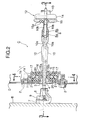
FIG. 2] FIG. 2 is a side view in which an essential part of the door checker is vertically sectioned (first embodiment). - [
FIG. 3] FIG. 3 is a sectional view along line 3-3 inFIG. 2 (first embodiment). - [
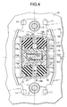
FIG. 4] FIG. 4 is an enlarged sectional view along line 4-4 inFIG. 2 (first embodiment). - [
FIG. 5] FIG. 5 is an exploded perspective view of an essential part of the door checker (first embodiment). - B Body
- C
- Door checker
- D
- Door
- 1
- Case
- 6
- Check plate
- 10
- Detent face
- 16
- Detent member
- 17
- Resilient member
- 18
- Housing chamber
- 18a
- Detent member outer end face
- 18b
- Case inner end face
- 20
- Hole portion
- 21
- Dividing wall
- 22
- Seal lip
- A preferred embodiment of the present invention is explained below by reference to the attached drawings.
- First, in
FIG. 1 , a door D is pivotably mounted on an automobile body B via a hinge H so as to open and close its entrance, and a door checker C of the present invention is mounted on the door D between the body B and the door D. - As shown in
FIG. 1 to FIG. 4 , the door checker C has a case 1 secured to an inner face of an end wall of the door D. This case 1 is formed from a box-shaped casemain body 1 a having one end open and acover 1b joined to the casemain body 1 a viaswage portions 11 and 11 (seeFIG. 4 ) while covering the open end, and the casemain body 1 a and thecover 1 b are secured to the end wall of the door D by means of a pair of upper andlower bolts cover 1b abuts against the inner face of the end wall. Thecover 1 b and the casemain body 1 a are provided with through holes 4 and 5 arranged coaxially with a throughhole 3 opening in the end wall of the door D, a base end of acheck plate 6 running through these three throughholes 3, 4, and 5 is coupled to abracket 7 via apivot 8 so that they are mutually pivotable, and thisbracket 7 is secured to the body B via abolt 9 so that thepivot 8 is disposed parallel to the pivot axis of the hinge H. Thecheck plate 6 is disposed substantially horizontally, and upper and lower faces thereof serve as detent faces 10 and 10. - The
check plate 6 is formed from a steel platemain body 6a directly coupled to thebracket 7 and disposed substantially horizontally and a syntheticresin covering body 6b mold-bonded to a peripheral face of the platemain body 6a apart from at opposite ends. The coveringbody 6b is formed so that a gap between the upper and lower detent faces 10 and 10 of thecheck plate 6 gradually increases from the base end side (thebracket 7 side) toward the free end side of theplate 6, a half-open detent notch 10a is formed in a longitudinally middle section of the detent faces 10 and 10, a fully-open detent notch 10b is formed in the vicinity of the free end portion, and a fully-open stopper 12 adjacent to the fully-open detent notch 10b is attached to the platemain body 6a. This fully-open stopper 12 is formed from asteel stopper plate 14 secured to the platemain body 6a via apin 13 and astopper rubber 15 mounted on thestopper plate 14 and facing the fully-open detent notch 10b, and a large number ofcushion projections 15a protrude from an end face of thestopper rubber 15 facing the fully-open detent notch 10b. The width of thecheck plate 6 is substantially constant apart from opposite ends thereof. - In
FIG. 2 to FIG. 5 , a pair of upper and lower syntheticresin detent members check plate 6, thedetent members check plate 6. Thesedetent members semi-cylindrical engagement portion 16a that can engage with the half-open detent notch 10a and the fully-open detent notch 10b. Furthermore, the twodetent members guide walls check plate 6 in cooperation with each other. - Moreover,
housing chambers detent members check plate 6 and upper and lower inner end faces 18b of the case 1 facing the outer end faces 18a, and a pair of upper and lowerresilient members housing chambers resilient members detent members check plate 6. - Each
resilient member 17 is formed from a resilient material such as an elastomer so that thehousing chamber 18 is substantially filled therewith and one half of theresilient member 17 on the outer end face 18a side of thedetent member 16 and the other half on theinner end face 18b side of the case 1 are symmetrical. Furthermore, eachresilient member 17 is formed so that a left half on the left inside face side of the case 1 and a right half on the right inside face side of the case 1 are symmetrical. - In the case of the illustrated example, a pair of
extension walls detent member 16 for lengthening the sliding span of thedetent member 16 relative to the two inner faces of the case 1, and in order to receive theseextension walls steps resilient member 17. In order to obtain the above-mentioned symmetrical shape, a pair ofsteps resilient member 17 on theinner end face 18b side of the case 1. - Furthermore, each
resilient member 17 is provided with a circularcross-section hole portion 20 opening on upper and lower end faces and allowing resilient deformation of theresilient member 17, and thehole portion 20 is divided by a dividingwall 21 integral with theresilient member 17 into twoportions annular seal lips hole portions resilient member 17, and thehole portions detent member 16 and the upper and lower inner end faces 18b of the case 1 coming into intimate contact with theseal lips - The operation of this embodiment is now explained.
- When the door D is opened from a closed state, since the
engagement portions detent members check plate 6, and theresilient members detent members - When the door D is opened to a predetermined half-open position, since the
engagement portions detent members open detent notches check plate 6 due to the resilient force of theresilient members - Furthermore, when the
engagement portions detent members open detent notches engagement portions open detent notches stopper rubber 15, thereby retaining the door D at the fully-open position. - Furthermore, in the course of the door D being closed from the fully-open position, in the same manner as above the door D can be retained at the predetermined half-open position due to engagement between the
engagement portions detent members open detent notches engagement portions detent members check plate 6, a closing torque for the door D decreases appropriately, thus enabling the closing to be carried out with little effort. - In this process, the
detent members detent notches resilient members hole portion 20 of each of theresilient members 17. - Since the
resilient member 17 is formed so that it substantially fills thehousing chamber 18 within the case 1, it is possible to prevent as far as possible rainwater from infiltrating into thehousing chamber 18. Moreover, since theresilient member 17 has thehole portion 20, which is sealed by the outer end face 18a of thedetent member 16 and the inner end face of the case 1, even if some rainwater infiltrates into thehousing chamber 18 and freezes, thehole portion 20 allows resilient deformation of theresilient member 17 as normal, and the resilient deformation characteristics of theresilient member 17 do not change, thus always maintaining a good opening and closing feel for the door D. - In particular, since the
hole portion 20 is divided into twoportions wall 21 integral with theresilient member 17, even if rainwater infiltrates into one half of thehole portion 20 and freezes, resilient deformation of theresilient member 17 can be allowed by the other half of thehole portion 20, which is free from the infiltration of rainwater, thus enhancing the reliability. - Furthermore, since the
annular seal lips resilient member 17, theannular seal lips hole portion 20 and being in intimate contact with the outer end face 18a and theinner end face 18b, it is possible to reliably prevent rainwater from infiltrating into thehole portion 20, thus further enhancing the reliability. Moreover, since thehole portion 20 opens on the outer face of theresilient member 17, this can easily be formed by means of a mold when molding theresilient member 17. - Furthermore, since the
hole portion 20 of theresilient member 17 has a circular cross-section, stress occurring on the inner peripheral wall of thehole portion 20 when theresilient member 17 is compressed and deformed can be equalized, thus contributing to an improvement in the durability of theresilient member 17. - Moreover, since the
resilient member 17 is formed so that a half on the side in which it is in intimate contact with the outer end face 18a and the other half on the side in which it is intimate contact with theinner end face 18b are symmetrical and, furthermore, a left half on the left inside face side of the case 1 and a right half on the right inside face side of the case 1 are symmetrical, it is unnecessary to restrict the direction of theresilient member 17 with respect to the outer end face 18a and theinner end face 18b in either the vertical direction or the lateral direction when fitting theresilient member 17 into thehousing chamber 18, the ease of assembly is good, and it is consequently possible to not only avoid misassembly but also for the proper function of theresilient member 17 to be always exhibited. - The present invention is not limited to the above-mentioned embodiment, and may be modified in a variety of ways as long as the modifications do not depart from the spirit and scope thereof. For example, when the
detent member 16 does not have theextension walls resilient member 17 may be formed with a simple rectangular cross-sectional shape without thesteps
Claims (5)
- An automobile door checker comprising a case (1) secured to one of an automobile body (B) and a door (D) pivotably supported on the automobile body (B), a check plate (6) that runs movably through the case (1) and is coupled to the other one of the body (B) and the door (D), a detent member (16) slidably fitted into and retained by the case (1) so as to retain the door (D) at a predetermined open position in cooperation with a detent face (10) of the check plate (6), and a resilient member (17) that is made of a resilient material, is provided in a compressed state in a housing chamber (18) defined between an outer end face (18a) of the detent member (16) on a side opposite to the check plate (6) and an inner end face (18b) of the case (1) opposite the outer end face (18a), and generates a detent force between the detent member (16) and the detent face (10),
characterized in that the resilient member (17) is formed so as to substantially fill the housing chamber (18), the resilient member (17) is provided with a hole portion (20) that allows resilient deformation of the resilient member (17), the hole portion (20) being sealed by the outer end face (18a) and the inner end face (18b), and one half of the resilient member (17) on the outer end face (18a) side and the other half on the inner end face (18b) side are symmetrical. - The automobile door checker according to Claim 1,
wherein the resilient member (17) is provided with a dividing wall (21) for dividing the hole portion (20) into two portions that are blocked from each other. - The automobile door checker according to Claim 1 or 2,
wherein annular seal lips (22) are formed on the outer face of the resilient member (17), the annular seal lips (22) surrounding an open end of the hole portion (20) and being in intimate contact with the outer end face (18a) and the inner end face (18b). - The automobile door checker according to any one of Claims 1 to 3,
wherein the hole portion (20) is formed so as to have a circular cross-section. - The automobile door checker according to Claim 1,
wherein a left half of the resilient member (17) on a left inside face side of the case (1) and a right half on a right inside face side of the case (1) are symmetrical.
Applications Claiming Priority (2)
| Application Number | Priority Date | Filing Date | Title |
|---|---|---|---|
| JP2005207481A JP4364171B2 (en) | 2005-07-15 | 2005-07-15 | Automotive door checker |
| PCT/JP2006/313946 WO2007010811A1 (en) | 2005-07-15 | 2006-07-13 | Door checker for automobile |
Publications (3)
| Publication Number | Publication Date |
|---|---|
| EP1908903A1 true EP1908903A1 (en) | 2008-04-09 |
| EP1908903A4 EP1908903A4 (en) | 2008-11-26 |
| EP1908903B1 EP1908903B1 (en) | 2009-08-19 |
Family
ID=37668693
Family Applications (1)
| Application Number | Title | Priority Date | Filing Date |
|---|---|---|---|
| EP06781066A Ceased EP1908903B1 (en) | 2005-07-15 | 2006-07-13 | Door checker for automobile |
Country Status (7)
| Country | Link |
|---|---|
| US (1) | US7913354B2 (en) |
| EP (1) | EP1908903B1 (en) |
| JP (1) | JP4364171B2 (en) |
| CN (1) | CN100529319C (en) |
| CA (1) | CA2612848C (en) |
| DE (1) | DE602006008626D1 (en) |
| WO (1) | WO2007010811A1 (en) |
Cited By (3)
| Publication number | Priority date | Publication date | Assignee | Title |
|---|---|---|---|---|
| GB2461519A (en) * | 2008-07-01 | 2010-01-06 | Jaguar Cars | Check arm with flow restrictor |
| DE202009012558U1 (en) | 2008-09-17 | 2010-02-11 | Edscha Ag | A door stay |
| FR3084019A1 (en) * | 2018-07-17 | 2020-01-24 | Renault S.A.S | ARRANGEMENT FOR PARTIALLY LOCKING A VEHICLE OPENING ELEMENT DURING OPENING AND / OR CLOSING |
Families Citing this family (12)
| Publication number | Priority date | Publication date | Assignee | Title |
|---|---|---|---|---|
| US7157584B2 (en) | 2004-02-25 | 2007-01-02 | Takeda Pharmaceutical Company Limited | Benzimidazole derivative and use thereof |
| JP2012193567A (en) * | 2011-03-17 | 2012-10-11 | Mitsui Kinzoku Act Corp | Door checker for automobile |
| JP6064239B2 (en) * | 2012-08-10 | 2017-01-25 | 三井金属アクト株式会社 | Check link device |
| US9316032B2 (en) | 2014-03-04 | 2016-04-19 | Honda Motor Co., Ltd. | Vehicle door checker |
| WO2015146754A1 (en) * | 2014-03-26 | 2015-10-01 | アイシン精機 株式会社 | Door opening degree adjustment device |
| US9458653B2 (en) | 2014-11-21 | 2016-10-04 | Nissan North America, Inc. | Check link structure |
| KR102403644B1 (en) * | 2017-07-05 | 2022-05-31 | 현대자동차주식회사 | Door checker device for vehicle |
| CN110094124A (en) * | 2018-01-30 | 2019-08-06 | 三井金属爱科特株式会社 | Limit linkage |
| CN110094125A (en) * | 2018-01-30 | 2019-08-06 | 三井金属爱科特株式会社 | Limit linkage |
| GB2577916B (en) * | 2018-10-10 | 2020-10-14 | Ford Global Tech Llc | A door check mechanism |
| GB2591096B (en) | 2020-01-14 | 2024-09-04 | Dawsongroup Plc | An inflatable structure and method of transporting an inflatable structure |
| US12545334B2 (en) | 2023-06-09 | 2026-02-10 | Ford Global Technologies, Llc | Assembly configured to operate as a hinge and door check for motor vehicle |
Family Cites Families (30)
| Publication number | Priority date | Publication date | Assignee | Title |
|---|---|---|---|---|
| US2268976A (en) * | 1940-04-26 | 1942-01-06 | Reconstruction Finance Corp | Door check |
| JPS5847271B2 (en) | 1981-01-27 | 1983-10-21 | 晃栄精機株式会社 | Self-propelled bevel cutting machine |
| JPH0210208Y2 (en) * | 1981-01-30 | 1990-03-14 | ||
| JPS58114363U (en) * | 1982-01-29 | 1983-08-04 | マツダ株式会社 | car door checker device |
| JPS60155698A (en) | 1984-01-24 | 1985-08-15 | Nippon Steel Corp | Method for partially electrolyzing steel sheet |
| JPS6263370A (en) | 1985-05-15 | 1987-03-20 | Toshiba Corp | Arithmetic circuit |
| JPS6263371A (en) | 1985-09-12 | 1987-03-20 | Toshiba Corp | Picture information retrieving network system |
| JPS6263370U (en) * | 1985-10-11 | 1987-04-20 | ||
| JPH0423171Y2 (en) * | 1986-09-30 | 1992-05-28 | ||
| JP2520651B2 (en) | 1987-07-24 | 1996-07-31 | セイレイ工業株式会社 | Swinging sorter in threshing sorter |
| JP2610959B2 (en) | 1988-09-14 | 1997-05-14 | 東日本旅客鉄道株式会社 | DC feeder circuit protection device |
| JP3086817B2 (en) | 1992-01-28 | 2000-09-11 | 株式会社城南製作所 | Car door hinges |
| JPH07145839A (en) | 1993-11-25 | 1995-06-06 | Kinugawa Rubber Ind Co Ltd | Bumper rubber |
| EP0674412B1 (en) | 1994-03-25 | 2004-07-14 | Samsung Electronics Co., Ltd. | Method and apparatus for automatic frequency control |
| JP3115981B2 (en) * | 1995-01-31 | 2000-12-11 | 株式会社大井製作所 | Automobile door check device |
| JPH08244457A (en) * | 1995-03-13 | 1996-09-24 | Hino Motors Ltd | Door check device for vehicle |
| JP3393281B2 (en) * | 1995-12-26 | 2003-04-07 | 株式会社大井製作所 | Car door check link |
| JP3052059B2 (en) | 1996-03-22 | 2000-06-12 | 理研化機工業株式会社 | Car door checker |
| DE19614713A1 (en) | 1996-04-13 | 1997-10-16 | Scharwaechter Gmbh Co Kg | Vehicular door restraint with pivoted holding bar and stop notches |
| JP3741825B2 (en) * | 1997-06-03 | 2006-02-01 | 理研化機工業株式会社 | Automotive door checker |
| JP3623095B2 (en) | 1998-02-24 | 2005-02-23 | 三菱ふそうトラック・バス株式会社 | Door checker |
| WO2000003110A2 (en) * | 1998-07-10 | 2000-01-20 | ED. SCHARWäCHTER GMBH | Doorstop |
| DE29905318U1 (en) | 1999-03-23 | 1999-08-05 | Basf Ag, 67063 Ludwigshafen | Stepless motion limiter for vibrating components |
| JP2001105863A (en) | 1999-10-07 | 2001-04-17 | Riken Seiko Kk | Car door checker |
| DE10025185C2 (en) * | 2000-05-20 | 2002-12-19 | Edscha Ag | Ball pressure slider door check |
| JP4503786B2 (en) | 2000-06-09 | 2010-07-14 | 株式会社エフ.イー.シーチェーン | Door check device |
| JP3632018B2 (en) * | 2002-08-21 | 2005-03-23 | 理研化機工業株式会社 | Automotive door checker |
| JP4015542B2 (en) | 2002-12-13 | 2007-11-28 | 理研化機工業株式会社 | Automotive door checker |
| FR2852995B1 (en) | 2003-03-25 | 2007-04-13 | Oxford Automotive Mecanismes E | IMPROVED VEHICLE DOOR STOP MECHANISM |
| US7143473B2 (en) * | 2005-01-13 | 2006-12-05 | Rikenkaki Kogyo Kabushiki Kaisha | Door checker for automobile |
-
2005
- 2005-07-15 JP JP2005207481A patent/JP4364171B2/en not_active Expired - Fee Related
-
2006
- 2006-07-13 CA CA2612848A patent/CA2612848C/en not_active Expired - Fee Related
- 2006-07-13 CN CNB2006800255610A patent/CN100529319C/en not_active Expired - Fee Related
- 2006-07-13 DE DE602006008626T patent/DE602006008626D1/en active Active
- 2006-07-13 WO PCT/JP2006/313946 patent/WO2007010811A1/en not_active Ceased
- 2006-07-13 US US11/922,863 patent/US7913354B2/en not_active Expired - Fee Related
- 2006-07-13 EP EP06781066A patent/EP1908903B1/en not_active Ceased
Cited By (4)
| Publication number | Priority date | Publication date | Assignee | Title |
|---|---|---|---|---|
| GB2461519A (en) * | 2008-07-01 | 2010-01-06 | Jaguar Cars | Check arm with flow restrictor |
| GB2461519B (en) * | 2008-07-01 | 2013-04-17 | Jaguar Cars | Vehicle door systems |
| DE202009012558U1 (en) | 2008-09-17 | 2010-02-11 | Edscha Ag | A door stay |
| FR3084019A1 (en) * | 2018-07-17 | 2020-01-24 | Renault S.A.S | ARRANGEMENT FOR PARTIALLY LOCKING A VEHICLE OPENING ELEMENT DURING OPENING AND / OR CLOSING |
Also Published As
| Publication number | Publication date |
|---|---|
| EP1908903A4 (en) | 2008-11-26 |
| JP4364171B2 (en) | 2009-11-11 |
| DE602006008626D1 (en) | 2009-10-01 |
| CN100529319C (en) | 2009-08-19 |
| CA2612848C (en) | 2010-08-17 |
| CN101223324A (en) | 2008-07-16 |
| CA2612848A1 (en) | 2007-01-25 |
| JP2007023614A (en) | 2007-02-01 |
| WO2007010811A1 (en) | 2007-01-25 |
| US20090217592A1 (en) | 2009-09-03 |
| EP1908903B1 (en) | 2009-08-19 |
| US7913354B2 (en) | 2011-03-29 |
Similar Documents
| Publication | Publication Date | Title |
|---|---|---|
| CA2612848C (en) | Automobile door checker | |
| JP2012193567A (en) | Door checker for automobile | |
| EP1862343B1 (en) | Glass run channel of automotive door window | |
| US20070040392A1 (en) | Door checker for automobile | |
| JP5239101B2 (en) | Automotive door check link device | |
| EP1908904B1 (en) | Door checker for automobile | |
| US9162635B2 (en) | Vehicle door | |
| JP2017177894A (en) | Sealant for automobile door | |
| EP2851226A2 (en) | Weatherstrip | |
| US20170015184A1 (en) | Weatherstrip for sunroof apparatus | |
| JP4857440B2 (en) | Vehicle door checker | |
| WO2024169701A1 (en) | Vehicle door limiter for vehicle, and vehicle | |
| CN113389451B (en) | A door mud discharge limiter | |
| CN112193039B (en) | Waterproof structure of door slide and door slide | |
| EP2307216B1 (en) | Vehicle door systems | |
| JP2015048658A (en) | Vehicle door checker | |
| JP2020079519A (en) | Vehicle door opening/closing assembly, opening/closing body drive device, door frame assembly, and vehicle door opening/closing assembly assembling method | |
| KR20040025306A (en) | Air extractor grille device for automobile | |
| JP2011099536A (en) | Check seal | |
| JP2004196033A (en) | Vehicle seal structure | |
| JP4572768B2 (en) | Glass run and its mounting structure | |
| JPH09310729A (en) | gas spring | |
| JPH08260797A (en) | Door check link device and assembling method thereof | |
| JP2006274668A (en) | Door holding structure |
Legal Events
| Date | Code | Title | Description |
|---|---|---|---|
| PUAI | Public reference made under article 153(3) epc to a published international application that has entered the european phase |
Free format text: ORIGINAL CODE: 0009012 |
|
| 17P | Request for examination filed |
Effective date: 20071221 |
|
| AK | Designated contracting states |
Kind code of ref document: A1 Designated state(s): DE GB |
|
| DAX | Request for extension of the european patent (deleted) | ||
| RBV | Designated contracting states (corrected) |
Designated state(s): DE GB |
|
| A4 | Supplementary search report drawn up and despatched |
Effective date: 20081024 |
|
| 17Q | First examination report despatched |
Effective date: 20081117 |
|
| GRAP | Despatch of communication of intention to grant a patent |
Free format text: ORIGINAL CODE: EPIDOSNIGR1 |
|
| GRAS | Grant fee paid |
Free format text: ORIGINAL CODE: EPIDOSNIGR3 |
|
| GRAA | (expected) grant |
Free format text: ORIGINAL CODE: 0009210 |
|
| AK | Designated contracting states |
Kind code of ref document: B1 Designated state(s): DE GB |
|
| REG | Reference to a national code |
Ref country code: GB Ref legal event code: FG4D |
|
| REF | Corresponds to: |
Ref document number: 602006008626 Country of ref document: DE Date of ref document: 20091001 Kind code of ref document: P |
|
| PLBE | No opposition filed within time limit |
Free format text: ORIGINAL CODE: 0009261 |
|
| STAA | Information on the status of an ep patent application or granted ep patent |
Free format text: STATUS: NO OPPOSITION FILED WITHIN TIME LIMIT |
|
| 26N | No opposition filed |
Effective date: 20100520 |
|
| PGFP | Annual fee paid to national office [announced via postgrant information from national office to epo] |
Ref country code: DE Payment date: 20190702 Year of fee payment: 14 |
|
| PGFP | Annual fee paid to national office [announced via postgrant information from national office to epo] |
Ref country code: GB Payment date: 20190710 Year of fee payment: 14 |
|
| REG | Reference to a national code |
Ref country code: DE Ref legal event code: R119 Ref document number: 602006008626 Country of ref document: DE |
|
| GBPC | Gb: european patent ceased through non-payment of renewal fee |
Effective date: 20200713 |
|
| PG25 | Lapsed in a contracting state [announced via postgrant information from national office to epo] |
Ref country code: GB Free format text: LAPSE BECAUSE OF NON-PAYMENT OF DUE FEES Effective date: 20200713 |
|
| PG25 | Lapsed in a contracting state [announced via postgrant information from national office to epo] |
Ref country code: DE Free format text: LAPSE BECAUSE OF NON-PAYMENT OF DUE FEES Effective date: 20210202 |