EP1908883A1 - External endplate gusseting for material pushing attachment - Google Patents
External endplate gusseting for material pushing attachment Download PDFInfo
- Publication number
- EP1908883A1 EP1908883A1 EP07117197A EP07117197A EP1908883A1 EP 1908883 A1 EP1908883 A1 EP 1908883A1 EP 07117197 A EP07117197 A EP 07117197A EP 07117197 A EP07117197 A EP 07117197A EP 1908883 A1 EP1908883 A1 EP 1908883A1
- Authority
- EP
- European Patent Office
- Prior art keywords
- attachment
- attached
- moldboard
- bracket
- blade
- Prior art date
- Legal status (The legal status is an assumption and is not a legal conclusion. Google has not performed a legal analysis and makes no representation as to the accuracy of the status listed.)
- Withdrawn
Links
Images


Classifications
-
- E—FIXED CONSTRUCTIONS
- E01—CONSTRUCTION OF ROADS, RAILWAYS, OR BRIDGES
- E01H—STREET CLEANING; CLEANING OF PERMANENT WAYS; CLEANING BEACHES; DISPERSING OR PREVENTING FOG IN GENERAL CLEANING STREET OR RAILWAY FURNITURE OR TUNNEL WALLS
- E01H5/00—Removing snow or ice from roads or like surfaces; Grading or roughening snow or ice
- E01H5/04—Apparatus propelled by animal or engine power; Apparatus propelled by hand with driven dislodging or conveying levelling elements, conveying pneumatically for the dislodged material
- E01H5/06—Apparatus propelled by animal or engine power; Apparatus propelled by hand with driven dislodging or conveying levelling elements, conveying pneumatically for the dislodged material dislodging essentially by non-driven elements, e.g. scraper blades, snow-plough blades, scoop blades
-
- E—FIXED CONSTRUCTIONS
- E02—HYDRAULIC ENGINEERING; FOUNDATIONS; SOIL SHIFTING
- E02F—DREDGING; SOIL-SHIFTING
- E02F3/00—Dredgers; Soil-shifting machines
- E02F3/04—Dredgers; Soil-shifting machines mechanically-driven
- E02F3/76—Graders, bulldozers, or the like with scraper plates or ploughshare-like elements; Levelling scarifying devices
- E02F3/80—Component parts
- E02F3/815—Blades; Levelling or scarifying tools
- E02F3/8157—Shock absorbers; Supports, e.g. skids, rollers; Devices for compensating wear-and-tear, or the like
Definitions
- Power machines such as skid steer loaders, mini-excavators, wheel loaders, and the like, often have utility attachments coupled to them to perform certain tasks.
- a power machine may be equipped with a bucket, a post-hole auger, a grader, a planer, or any one of a variety of other different types of attachments.
- One other particular type of attachment is a material pushing attachment.
- Such attachments can push material such as snow for the purpose of removing the material from a particular area.
- a power machine equipped with a material pushing attachment can be used to clear a parking lot covered in snow after a snowfall. Other materials besides snow, of course, can be pushed by such an attachment to move it out of a particular area.
- Attachments of this type typically have a blade or moldboard that engages the material to push it to a desired location.
- the moldboard typically has a concave surface to encourage material that might ride up onto the moldboard to roll forward in front of the attachment instead of over the top of the attachment.
- these types of attachments may have end plates attached to the moldboard to provide a defined width of material that is pushed by the attachment on one given pass over the area to be cleared by the power machine and to provide structural support for the moldboard. To prevent deformation or fatigue related damage to the moldboard, it is desirable to provide reinforcement for the moldboard.
- One illustrative embodiment is directed toward an attachment that is configured to be attached to a power machine.
- the attachment includes a blade having opposing first and second major surfaces and first and second edges.
- the attachment further includes first and second end plates.
- Each of the first and second end plates have opposing inner and outer surfaces fixedly attached to the first and second edges of the blade.
- the inner surfaces of the first and second end plates are positioned adjacent to and extend from the first major surface of the blade.
- the attachment also includes a support structure coupled to the blade and including a first support member fixedly attached to and extending from the second major surface of the blade and the outer surface of the first end plate.
- the attachment includes a moldboard having opposing first and second major surfaces and first and second ends.
- the attachment further includes a plate that is attached to the moldboard and extends distally from the moldboard.
- a coupling structure extends proximally from the second major surface of the moldboard.
- a bracket is fixedly coupled to the second major surface of the moldboard and a portion of the plate that is positioned distally from the first major surface of the moldboard.
- Still another embodiment is directed toward a loader having a frame and lift arms pivotally mounted to the frame.
- the lift arms have an interface member pivotally coupled to the thereto and are configured to accept an attachment thereon.
- the attachment includes a horizontally extending member with first and second ends.
- An endplate is attached to the first end of the horizontally extending surface.
- the endplate has an inner surface adjacent the horizontally extending member and an outer surface opposite the inner surface.
- a bracket is attached to the horizontally extending member and the outer surface of the end plate.
- FIG. 1 illustrates a power machine 10 of the type that is useful for employing an attachment of the current disclosure.
- Power machine 10 includes a frame 12 that is supported by wheels 14.
- Power machine 10 has an engine (not shown), which supplies power to the wheels 14 causing the power machine to move under the control of an operator.
- Frame 12 supports a cab 16, which defines an operating compartment. An operator can sit inside the cab 16 and control the power machine 10.
- Power machine 10 further includes a lift arm 18, which is coupled to the frame 12 at pivot point 26.
- Actuator 20 is coupled to the frame 12 at first pivot point 22 and the lift arm 18 at second pivot point 24.
- actuator 20 is a hydraulic cylinder.
- a single lift arm 18 is shown in FIG. 1, but it is to be understood that a similar lift arm and corresponding actuator may be positioned on the opposite side of the cab and similarly attached to the frame 12.
- the lift arm 18 By extending or retracting the actuator 20, the lift arm 18 can be raised or lowered in the general direction shown by arrow 36.
- the actual path of motion of the lift arm 18 may vary.
- the path of motion can be a generally radial path as shown as by arrow 36.
- Alternative lift arms and geometrical relationships between the lift arm actuator, and frame can result in other paths of motion for the lift arm.
- the lift arm 18 can raise and lower in a generally vertical path.
- Power machine 10 further includes an attachment interface 28, which is rotatably coupled to the lift arm 18 about attachment point 30.
- One or more tilt actuators are coupled to the attachment interface 28 to cause the attachment interface to rotate about attachment point 30 in a direction shown by arrow 38.
- Attachment interface 28 further includes an edge 34, which is configured to engage a mount on an attachment.
- the attachment interface 28 includes one or more retractable pins 32 (shown in an extended position in FIG. 1). The pins 32 can be extended or retracted so that when the mount of an attachment is engaged with the edge 34 the pins 32 can extend into apertures in the attachment to secure the attachment to the power machine 10. Details of the attachment features that engage both the edge 34 and the pins 32 will be described in more detail below.
- the power machine 10 shown in FIG. 1 is a skid steer loader.
- the attachments discussed below are capable of interfacing with a number of different types of power machines.
- the power machine 10 can be a mini excavator, wheeled or tracked loader, utility vehicle, all-wheel steer loader, or a walk behind loader, to name a few.
- FIGs. 2-4 illustrate an attachment 100 configured to be attached to power machine 10 according to one illustrative embodiment.
- Attachment 100 includes a blade or moldboard 102 that extends transversely from a first end 104 to a second end 106 with respect to power machine 10 when attached thereto.
- Moldboard 102 has a generally concave first major surface 108 and an opposing generally convex second major surface 110. Moldboard 102 is configured so that the first major surface 108 is positioned to engage material and push it.
- attachment 100 can be used to push snow, debris, or any number of different types of material that is desirably repositioned.
- a cutting edge 114 is positioned along and attached to a lateral edge 112 of the moldboard 102.
- the cutting edge 114 is shown as being attached to the moldboard 102 with a plurality of fasteners 116.
- the cutting edge 114 is replaceable with respect to the moldboard 102.
- the cutting edge 114 can be permanently attached to the moldboard 102 such as by being welded along the lateral edge 112 of the moldboard 102.
- attachment 100 can have a moldboard 102 that does not have a cutting edge 114 attached to it.
- Attachment 100 further includes a pair of end plates 118.
- the end plates 118 are attached to the first end 104 and the second end 106 of the moldboard 102 at a proximal end 120 of each of the respective end plates 118.
- the end plates 118 extend distally from the first major surface 108 of the moldboard 102 toward a distal end 122 of the end plates 118.
- Each of the end plates 118 has an inner surface 124 that is positioned to be facing the moldboard 102 when the end plates 118 are attached to the moldboard 102.
- each end plate 118 has an outer surface 126 that opposes the inner surface 124.
- a pair of skid plates 130 are attached to each of the end plates 118.
- Each of the skid plates 130 has a base 132 that is positioned generally in a normal attitude with respect to the end plates 118.
- the base 132 provides an engagement surface for the attachment 100.
- Skid plates 130 are, in one illustrative embodiment, fastened to the end plates 118 with a plurality of fasteners 128.
- the skid plates 130 can be removable. This allows a user to replace the skid plates 130 when they become worn and thereby prevent other portions of the attachment 100 from wearing because of engagement with any surface that the attachment 100 may contact.
- Attachment 100 includes a support structure 136.
- Support structure 136 is coupled to the moldboard 102.
- the support structure 136 includes a base 138, which is attached to the moldboard 102 and projects proximally from the moldboard 102.
- a pair of vertical support members 140 extend vertically from the base 138 and are similarly attached to the second major surface 110 of moldboard 102.
- the support structure 136 also includes a cross member 142, which extends along a substantial, if not the entire, transverse length of the second major surface 110 of the moldboard 102.
- the cross member 142 is attached to the moldboard 102, such as by welding, and is also attached to the vertical support members 140.
- the cross member 142 is attached to each of the end plates 118.
- the base 138 of support structure 136 has a pivot mount 144.
- the pivot mount 144 provides a pivotable attachment point between an interface mount 174 and the support structure 136.
- Mount 174 is configured to be attached to power machine 10 at the attachment interface 28 shown in FIG. 1.
- Interface mount 174 has a major surface 176, which is configured to be positioned against the attachment interface 28 on the power machine 10 (shown in FIG 1).
- the interface mount 174 includes a lip 178 and apertures 180. The lip 178 is configured to engage the edge 34 of the attachment interface 28.
- An actuator 168 is positioned between and attached to a moldboard attachment point 170 and a mount attachment point 172. When the actuator 168 is actuated, the support structure 136 pivots with respect to the mount 174.
- Support structure 136 also includes a first reinforcement member 150 and a second reinforcement member 152.
- the first reinforcement member 150 extends along a portion of the second major surface 110 of the moldboard 102.
- the first reinforcement member 150 extends along, and is attached to, a portion of the outer surface 126 of the end plate 118 and the first end 104 of moldboard 102.
- the second reinforcement member 152 extends along a portion of the second major surface 110 of the moldboard 102.
- the second reinforcement member 152 also extends along, and is attached to, the outer surface 126 of the end plate 118 and the second end 106 of moldboard 102.
- Each of the first and second reinforcement members 150 and 152 is fixedly attached or secured to the moldboard 102 and its respective end plate 118.
- a portion of each of the first and second reinforcement members 150 and 152 extends through each of the end plates 118 and a moldboard 102.
- slots may be formed in each of the end plate 118 and moldboard 102 to allow the members 150 and 152 to extend through them.
- the portion 154 of each of the first and second reinforcement members 150 and 152 that extends through the moldboard 102 and end plates 118 is attached to the moldboard 102 and its respective end plate 118 along the first major surface of 108 of a moldboard 102 and the inner surface 124 of the end plate 118.
- This attachment can be accomplished such as by a weld at an edge 164.
- the members 150 and 152 can be positioned so that they do not extend through either of the end plates 118 or the moldboard 102. In that case, the members 150 and 152 would engage, and be attached to, only the outer surface 126 of one of the end plates 118 and the second major surface 110 of the moldboard 102.
- each of the first reinforcement member 150 and the second reinforcement member 152 has a first portion 160 and a second portion 162.
- the first portion 160 and the second portion 162 are shown as being integrally joined together to provide a single, unitary piece of material, although alternatively the first and second portions can be two separate pieces of material that are attached to each other.
- the first portion 160 is a generally flat piece of material, which extends along the second major surface 110 of the moldboard 102 and is attached to the moldboard along an edge of the flat surface.
- the first portion 160 of the first and second reinforcement members 150 and 152 includes, in one embodiment, the portion 154 that extends from the inner surface 126 of the end plate 118 and the first major surface 108 of the moldboard 102.
- the second portion 162 of each of the first and second reinforcement members 150 and 152 extends distally from the first portion 160 and can depart from the planarity of the first portion 160 at any angle.
- the second portion 162 is likewise attached to the outer surface 126 of the respective end plates 118 along an edge of the second portion, thereby creating a pair of legs 164 and 166, attached to the end plate 118, that are non-planar with respect to each other.
- the first and second reinforcement members 150 and 152 extend transversely that, is, in a lateral direction, away from the outer surfaces 126 of their respective end plates 118. However, in one illustrative embodiment, the lateral extension of each of the first and second reinforcement members 150 and 152 is limited so that it is within the lateral extension of the skid plates 130. Thus, the attachment can be maneuvered into areas unencumbered by the lateral extension of the first and second reinforcement members 150 and 152. It should be appreciated that although the first and second reinforcement members 150 and 152 are shown as a unitary piece of material, alternatively they can be made of two or more pieces of material that are attached together. Alternatively still, the first and second reinforcement members 150 and 152 can be made of a single unitary piece of material. Alternatively still, the first and second reinforcement members 150 and 152 can include at least the first and second portions 160 and 162 that are not attached to each other.
- the embodiments described herein provide several advantages.
- the support structure reduces the possibility of a structural failure of the attachment.
- the attachment has a generally smooth first major surface of the moldboard. This encourages material being pushed by the attachment to roll forward without significant obstruction as opposed to potentially sticking on the attachment.
- the lateral extension of the reinforcing members are contained within the lateral extension of the skid plates, thereby allowing the attachment to maneuver in tight areas without being limited by the reinforcing members.
Landscapes
- Engineering & Computer Science (AREA)
- Civil Engineering (AREA)
- Structural Engineering (AREA)
- Mechanical Engineering (AREA)
- Mining & Mineral Resources (AREA)
- General Engineering & Computer Science (AREA)
- Architecture (AREA)
- Body Structure For Vehicles (AREA)
- Connection Of Plates (AREA)
Abstract
Description
- Power machines, such as skid steer loaders, mini-excavators, wheel loaders, and the like, often have utility attachments coupled to them to perform certain tasks. For example, a power machine may be equipped with a bucket, a post-hole auger, a grader, a planer, or any one of a variety of other different types of attachments. One other particular type of attachment is a material pushing attachment. Such attachments can push material such as snow for the purpose of removing the material from a particular area. For example, a power machine equipped with a material pushing attachment can be used to clear a parking lot covered in snow after a snowfall. Other materials besides snow, of course, can be pushed by such an attachment to move it out of a particular area.
- Attachments of this type typically have a blade or moldboard that engages the material to push it to a desired location. The moldboard typically has a concave surface to encourage material that might ride up onto the moldboard to roll forward in front of the attachment instead of over the top of the attachment. In addition, these types of attachments may have end plates attached to the moldboard to provide a defined width of material that is pushed by the attachment on one given pass over the area to be cleared by the power machine and to provide structural support for the moldboard. To prevent deformation or fatigue related damage to the moldboard, it is desirable to provide reinforcement for the moldboard.
- One illustrative embodiment is directed toward an attachment that is configured to be attached to a power machine. The attachment includes a blade having opposing first and second major surfaces and first and second edges. The attachment further includes first and second end plates. Each of the first and second end plates have opposing inner and outer surfaces fixedly attached to the first and second edges of the blade. The inner surfaces of the first and second end plates are positioned adjacent to and extend from the first major surface of the blade. The attachment also includes a support structure coupled to the blade and including a first support member fixedly attached to and extending from the second major surface of the blade and the outer surface of the first end plate.
- Another illustrative is directed toward an attachment configured to push material. The attachment includes a moldboard having opposing first and second major surfaces and first and second ends. The attachment further includes a plate that is attached to the moldboard and extends distally from the moldboard. A coupling structure extends proximally from the second major surface of the moldboard. A bracket is fixedly coupled to the second major surface of the moldboard and a portion of the plate that is positioned distally from the first major surface of the moldboard.
- Still another embodiment is directed toward a loader having a frame and lift arms pivotally mounted to the frame. The lift arms have an interface member pivotally coupled to the thereto and are configured to accept an attachment thereon. The attachment includes a horizontally extending member with first and second ends. An endplate is attached to the first end of the horizontally extending surface. The endplate has an inner surface adjacent the horizontally extending member and an outer surface opposite the inner surface. A bracket is attached to the horizontally extending member and the outer surface of the end plate.
-
- FIG. 1 is a side elevation view of a power machine of the type suitable for use with an attachment of the typed discussed herein.
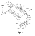
- FIG. 2 is a perspective view of a material pushing attachment having a moldboard with attached endplates and a reinforcement member attached to each shown along a first major surface the moldboard according to one embodiment.
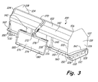
- FIG. 3 is a perspective view of the attachment of FIG. 2 viewed along a second major surface of the moldboard.
- FIG. 4 is a side elevation view of the attachment of FIG. 2.
- The concepts presented herein will be further explained with reference to the attached figures, wherein like structure or system elements can be referred to by like reference numerals throughout the several views.
- While the above-identified figures set forth one or more illustrative embodiments, other embodiments are also contemplated, as noted herein. In all cases, concepts presented herein describe the embodiments by way of representation and not by limitation. It should be understood that numerous other modifications and embodiments can be devised by those skilled in the art which fall within the scope and spirit of the principles of the discussion herein.
- FIG. 1 illustrates a
power machine 10 of the type that is useful for employing an attachment of the current disclosure.Power machine 10 includes aframe 12 that is supported bywheels 14.Power machine 10 has an engine (not shown), which supplies power to thewheels 14 causing the power machine to move under the control of an operator.Frame 12 supports acab 16, which defines an operating compartment. An operator can sit inside thecab 16 and control thepower machine 10. -
Power machine 10 further includes alift arm 18, which is coupled to theframe 12 atpivot point 26.Actuator 20 is coupled to theframe 12 at first pivot point 22 and thelift arm 18 atsecond pivot point 24. In one illustrative embodiment,actuator 20 is a hydraulic cylinder. Asingle lift arm 18 is shown in FIG. 1, but it is to be understood that a similar lift arm and corresponding actuator may be positioned on the opposite side of the cab and similarly attached to theframe 12. - By extending or retracting the
actuator 20, thelift arm 18 can be raised or lowered in the general direction shown by arrow 36. The actual path of motion of thelift arm 18 may vary. For example, the path of motion can be a generally radial path as shown as by arrow 36. Alternative lift arms and geometrical relationships between the lift arm actuator, and frame can result in other paths of motion for the lift arm. For example, thelift arm 18 can raise and lower in a generally vertical path. -
Power machine 10 further includes anattachment interface 28, which is rotatably coupled to thelift arm 18 aboutattachment point 30. One or more tilt actuators (not shown) are coupled to theattachment interface 28 to cause the attachment interface to rotate aboutattachment point 30 in a direction shown byarrow 38.Attachment interface 28 further includes anedge 34, which is configured to engage a mount on an attachment. In addition, theattachment interface 28 includes one or more retractable pins 32 (shown in an extended position in FIG. 1). Thepins 32 can be extended or retracted so that when the mount of an attachment is engaged with theedge 34 thepins 32 can extend into apertures in the attachment to secure the attachment to thepower machine 10. Details of the attachment features that engage both theedge 34 and thepins 32 will be described in more detail below. - The
power machine 10 shown in FIG. 1 is a skid steer loader. However, it should be appreciated that the attachments discussed below are capable of interfacing with a number of different types of power machines. For example, thepower machine 10 can be a mini excavator, wheeled or tracked loader, utility vehicle, all-wheel steer loader, or a walk behind loader, to name a few. - FIGs. 2-4 illustrate an
attachment 100 configured to be attached topower machine 10 according to one illustrative embodiment.Attachment 100 includes a blade ormoldboard 102 that extends transversely from afirst end 104 to asecond end 106 with respect topower machine 10 when attached thereto. Moldboard 102 has a generally concave firstmajor surface 108 and an opposing generally convex secondmajor surface 110.Moldboard 102 is configured so that the firstmajor surface 108 is positioned to engage material and push it. For example,attachment 100 can be used to push snow, debris, or any number of different types of material that is desirably repositioned. - A
cutting edge 114 is positioned along and attached to alateral edge 112 of themoldboard 102. Thecutting edge 114 is shown as being attached to themoldboard 102 with a plurality offasteners 116. Thus, thecutting edge 114 is replaceable with respect to themoldboard 102. Alternatively, thecutting edge 114 can be permanently attached to themoldboard 102 such as by being welded along thelateral edge 112 of themoldboard 102. Alternatively still,attachment 100 can have amoldboard 102 that does not have acutting edge 114 attached to it. -
Attachment 100 further includes a pair ofend plates 118. Theend plates 118 are attached to thefirst end 104 and thesecond end 106 of themoldboard 102 at aproximal end 120 of each of therespective end plates 118. Thus, theend plates 118 extend distally from the firstmajor surface 108 of themoldboard 102 toward adistal end 122 of theend plates 118. Each of theend plates 118 has aninner surface 124 that is positioned to be facing themoldboard 102 when theend plates 118 are attached to themoldboard 102. In addition, eachend plate 118 has anouter surface 126 that opposes theinner surface 124. - A pair of
skid plates 130 are attached to each of theend plates 118. Each of theskid plates 130 has a base 132 that is positioned generally in a normal attitude with respect to theend plates 118. Thebase 132 provides an engagement surface for theattachment 100. Thus, for example, asattachment 100 is moved bypower machine 10 over a terrain, theskid plate 130 is configured to engage the terrain when the attachment is in a lowered position. Skidplates 130 are, in one illustrative embodiment, fastened to theend plates 118 with a plurality offasteners 128. Thus, theskid plates 130 can be removable. This allows a user to replace theskid plates 130 when they become worn and thereby prevent other portions of theattachment 100 from wearing because of engagement with any surface that theattachment 100 may contact. -
Attachment 100 includes asupport structure 136.Support structure 136 is coupled to themoldboard 102. In the illustrative embodiment, thesupport structure 136 includes abase 138, which is attached to themoldboard 102 and projects proximally from themoldboard 102. A pair ofvertical support members 140 extend vertically from thebase 138 and are similarly attached to the secondmajor surface 110 ofmoldboard 102. Thesupport structure 136 also includes across member 142, which extends along a substantial, if not the entire, transverse length of the secondmajor surface 110 of themoldboard 102. Thecross member 142 is attached to themoldboard 102, such as by welding, and is also attached to thevertical support members 140. In addition, thecross member 142 is attached to each of theend plates 118. - The
base 138 ofsupport structure 136 has apivot mount 144. Thepivot mount 144 provides a pivotable attachment point between aninterface mount 174 and thesupport structure 136.Mount 174 is configured to be attached topower machine 10 at theattachment interface 28 shown in FIG. 1.Interface mount 174 has amajor surface 176, which is configured to be positioned against theattachment interface 28 on the power machine 10 (shown in FIG 1). In addition, theinterface mount 174 includes alip 178 andapertures 180. Thelip 178 is configured to engage theedge 34 of theattachment interface 28. When theedge 34 and thelip 178 are engaged, and themajor surface 176 of theinterface mount 174 is positioned adjacent theattachment interface 28 so that thepins 32 are aligned with theapertures 180, pins 32 can be extended into theapertures 180 to securely hold theattachment 100. Anactuator 168 is positioned between and attached to amoldboard attachment point 170 and amount attachment point 172. When theactuator 168 is actuated, thesupport structure 136 pivots with respect to themount 174. -
Support structure 136 also includes afirst reinforcement member 150 and asecond reinforcement member 152. Thefirst reinforcement member 150 extends along a portion of the secondmajor surface 110 of themoldboard 102. In addition, thefirst reinforcement member 150 extends along, and is attached to, a portion of theouter surface 126 of theend plate 118 and thefirst end 104 ofmoldboard 102. Similarly, thesecond reinforcement member 152 extends along a portion of the secondmajor surface 110 of themoldboard 102. Thesecond reinforcement member 152 also extends along, and is attached to, theouter surface 126 of theend plate 118 and thesecond end 106 ofmoldboard 102. - Each of the first and
second reinforcement members moldboard 102 and itsrespective end plate 118. In addition, a portion of each of the first andsecond reinforcement members end plates 118 and amoldboard 102. For example, slots (not shown) may be formed in each of theend plate 118 andmoldboard 102 to allow themembers portion 154 of each of the first andsecond reinforcement members moldboard 102 andend plates 118 is attached to themoldboard 102 and itsrespective end plate 118 along the first major surface of 108 of amoldboard 102 and theinner surface 124 of theend plate 118. This attachment can be accomplished such as by a weld at anedge 164. Alternatively, themembers end plates 118 or themoldboard 102. In that case, themembers outer surface 126 of one of theend plates 118 and the secondmajor surface 110 of themoldboard 102. - In one illustrative embodiment, each of the
first reinforcement member 150 and thesecond reinforcement member 152 has afirst portion 160 and asecond portion 162. Thefirst portion 160 and thesecond portion 162 are shown as being integrally joined together to provide a single, unitary piece of material, although alternatively the first and second portions can be two separate pieces of material that are attached to each other. - The
first portion 160 is a generally flat piece of material, which extends along the secondmajor surface 110 of themoldboard 102 and is attached to the moldboard along an edge of the flat surface. Thefirst portion 160 of the first andsecond reinforcement members portion 154 that extends from theinner surface 126 of theend plate 118 and the firstmajor surface 108 of themoldboard 102. Thesecond portion 162 of each of the first andsecond reinforcement members first portion 160 and can depart from the planarity of thefirst portion 160 at any angle. Thesecond portion 162 is likewise attached to theouter surface 126 of therespective end plates 118 along an edge of the second portion, thereby creating a pair oflegs end plate 118, that are non-planar with respect to each other. - The first and
second reinforcement members outer surfaces 126 of theirrespective end plates 118. However, in one illustrative embodiment, the lateral extension of each of the first andsecond reinforcement members skid plates 130. Thus, the attachment can be maneuvered into areas unencumbered by the lateral extension of the first andsecond reinforcement members second reinforcement members second reinforcement members second reinforcement members second portions - The embodiments described herein provide several advantages. The support structure reduces the possibility of a structural failure of the attachment. In addition, the attachment has a generally smooth first major surface of the moldboard. This encourages material being pushed by the attachment to roll forward without significant obstruction as opposed to potentially sticking on the attachment. Further, the lateral extension of the reinforcing members are contained within the lateral extension of the skid plates, thereby allowing the attachment to maneuver in tight areas without being limited by the reinforcing members.
- Although the discussion has been focused upon illustrative embodiments, workers skilled in the art will recognize that changes may be made in form and detail without departing from the spirit and the scope of the discussion.
- Attention is directed to all papers and documents which are filed concurrently with or previous to this specification in connection with this application and which are open to public inspection with this specification, and the contents of all such papers and documents are incorporated herein by reference.
- All of the features disclosed in this specification (including any accompanying claims, abstract and drawings), and/or all of the steps of any method or process so disclosed, may be combined in any combination, except combinations where at least some of such features and/or steps are mutually exclusive.
- Each feature disclosed in this specification (including any accompanying claims, abstract and drawings) may be replaced by alternative features serving the same, equivalent or similar purpose, unless expressly stated otherwise. Thus, unless expressly stated otherwise, each feature disclosed is one example only of a generic series of equivalent or similar features.
- The invention is not restricted to the details of the foregoing embodiment(s). The invention extends to any novel one, or any novel combination, of the features disclosed in this specification (including any accompanying claims, abstract and drawings), or to any novel one, or any novel combination, of the steps of any method or process so disclosed.
Claims (18)
- An attachment configured to be attached to a power machine, comprising:a blade having opposing first and second major surfaces and first and second edges;first and second end plates each having opposing inner and outer surfaces fixedly attached to the first and second edges of the blade with the inner surfaces of the first and second end plates positioned adjacent to and extending from the first major surface of the blade; anda support structure, coupled to the blade and including a first support member fixedly attached to and extending from the second major surface of the blade and the outer surface of the first end plate.
- The attachment of claim 1, wherein the first bracket extends through the blade and is attached to the inner surface of the first end plate.
- The attachment of claim 1, further comprising a skid plate attached to the first end plate, the skid plate extending away from the outer surface of the first end plate in a direction that is generally normal to the outer surface of the first end plate, wherein the skid plate extends at least as far in the direction as the first bracket.
- The attachment of claim 3, wherein the skid plate is removably attached to the first end plate.
- The attachment of claim 1, wherein the first bracket has a first portion that is generally planar and a second portion that non-planar with respect to from the generally planar first portion.
- The attachment of claim 5, wherein the first portion of the first bracket is attached to the blade and the outer surface of the first end plate.
- The attachment of claim 6, wherein the second portion of the first bracket is attached to the outer portion of the first end plate.
- The attachment of claim 5, wherein the first portion and the second portion are made from a unitary piece of material.
- The attachment of claim 1, wherein the support structure includes a second bracket fixedly attached to and extending from the second major surface of the blade and the outer surface of the second end plate.
- The attachment of claim 9, wherein the first bracket and the second bracket are formed from a single unitary piece of material.
- An attachment configured to push material, comprising:a moldboard having opposing first and second major surfaces and first and second ends;a plate attached to the moldboard and extending distally from the moldboard;a coupling structure extending proximally from the second major surface of the moldboard; anda bracket fixedly coupled to the second major surface of the moldboard and a portion of the plate that is positioned distally from the first major surface of the moldboard.
- The attachment of claim 11, wherein the plate has first and second opposing sides and wherein the bracket is attached to both the first side and the second side.
- The attachment of claim 11, wherein the bracket is attached to both the first major surface and the second major surface of the moldboard.
- The attachment of claim 11, wherein the bracket has a first portion and a second portion, and wherein the first portion is attached to the moldboard and the second portion is attached to the plate.
- The attachment of claim 14, wherein the second portion has a first leg and a second leg, and wherein the second leg is non-planar with respect to the first leg.
- The attachment of claim 15, wherein both the first leg and the second leg are attached to the plate.
- The attachment of claim 16 wherein the first leg is planar with respect to the first portion of the bracket.
- A loader having a frame and lift arms pivotally mounted to the frame, the lift arms having an interface member pivotally coupled to the thereto and configured to accept an attachment thereon, the attachment comprising:a horizontally extending member with first and second ends;an endplate attached to the first end of the horizontally extending surface having an inner surface adjacent the horizontally extending member and an outer surface opposite the inner surface; anda bracket attached to the horizontally extending member and the outer surface of the end plate.
Applications Claiming Priority (1)
| Application Number | Priority Date | Filing Date | Title |
|---|---|---|---|
| US11/542,724 US7588092B2 (en) | 2006-10-04 | 2006-10-04 | External endplate gusseting for material pushing attachment |
Publications (1)
| Publication Number | Publication Date |
|---|---|
| EP1908883A1 true EP1908883A1 (en) | 2008-04-09 |
Family
ID=38896610
Family Applications (1)
| Application Number | Title | Priority Date | Filing Date |
|---|---|---|---|
| EP07117197A Withdrawn EP1908883A1 (en) | 2006-10-04 | 2007-09-25 | External endplate gusseting for material pushing attachment |
Country Status (4)
| Country | Link |
|---|---|
| US (1) | US7588092B2 (en) |
| EP (1) | EP1908883A1 (en) |
| CN (1) | CN101158166A (en) |
| CA (1) | CA2605048A1 (en) |
Families Citing this family (8)
| Publication number | Priority date | Publication date | Assignee | Title |
|---|---|---|---|---|
| US20080313933A1 (en) * | 2007-06-19 | 2008-12-25 | James Dwain Cooper | Backfill attachment device |
| US8689897B2 (en) * | 2010-12-18 | 2014-04-08 | Caterpillar Inc. | Tractor blade assembly |
| CN102900046B (en) * | 2012-09-30 | 2015-02-11 | 常州市德思特机械有限公司 | Snow sweeper |
| US10227751B2 (en) * | 2015-01-15 | 2019-03-12 | WJN Enterprises, Inc. | Sectional plow |
| US10801172B2 (en) * | 2018-02-20 | 2020-10-13 | Buyers Products Company | Snow plow assembly with floating a-frame |
| US20190330814A1 (en) * | 2018-04-30 | 2019-10-31 | Ozcan Yildiz | Shovel pusher and related systems and methods |
| US12312759B2 (en) | 2020-09-23 | 2025-05-27 | Buyers Products Company | Snow plow assembly with floating a-frame |
| US12595636B2 (en) | 2022-07-19 | 2026-04-07 | Bourgault Machines Inc. | Back-drag bucket accessory |
Citations (5)
| Publication number | Priority date | Publication date | Assignee | Title |
|---|---|---|---|---|
| US4999022A (en) | 1987-06-05 | 1991-03-12 | Veys Jeff M | Bucket-blade attachment for tractors |
| US5724755A (en) | 1996-10-28 | 1998-03-10 | Weagley; Michael P. | Snow pusher |
| US5819444A (en) * | 1996-06-20 | 1998-10-13 | Desmarais; Denis | Snow blade with tiltable lateral panels |
| US6425196B1 (en) | 2000-08-08 | 2002-07-30 | Pro-Tech Welding And Fabrication, Inc. | Folding pusher |
| US20030061741A1 (en) | 2001-06-15 | 2003-04-03 | Guggino Michael J. | Compact material pusher with universal design and method of manufacture |
Family Cites Families (16)
| Publication number | Priority date | Publication date | Assignee | Title |
|---|---|---|---|---|
| US1579388A (en) * | 1924-04-18 | 1926-04-06 | Dail Steel Products Company | Metal wagon body |
| US3605167A (en) * | 1969-03-12 | 1971-09-20 | Andre J Martel | Wing gutter cleaner |
| US4275514A (en) * | 1980-01-28 | 1981-06-30 | Maura Nicholas J | Snowplow extensions |
| US4707936A (en) * | 1986-07-21 | 1987-11-24 | Kenneth Steinhoff | Snow plow attachment |
| US5285588A (en) * | 1992-07-13 | 1994-02-15 | W. Wally Niemela | Winged plow |
| US5265355A (en) * | 1992-12-15 | 1993-11-30 | Daniels Pull Plow, Inc. | Rear-mounted snow plow apparatus |
| US5392538A (en) * | 1993-06-02 | 1995-02-28 | Geerligs; Gerald J. | Extendable drag plow |
| US5894689A (en) * | 1996-07-19 | 1999-04-20 | Turk; Roger E. | Free floating, self-leveling, instant mounting side-shield wing attachments for general utility grading flows |
| US6112438A (en) * | 1998-08-14 | 2000-09-05 | Pro-Tech Welding & Fabrication, Inc. | Snow plow |
| US6470604B1 (en) * | 2000-07-20 | 2002-10-29 | Farmers' Factory Company | Snowplow attachment for pushing and pulling snow up close to buildings or other permanent structures |
| US6298585B1 (en) * | 2000-07-28 | 2001-10-09 | Boulet Brothers Concrete Ltd. | Wing accessory for use on the bucket of a loader |
| US7131221B2 (en) * | 2001-11-12 | 2006-11-07 | Agri-Cover, Inc. | Self-adjusting snow plow |
| US6845576B2 (en) * | 2002-11-21 | 2005-01-25 | Robert G. Vennard | Materials moving blade |
| US20050126051A1 (en) * | 2003-12-16 | 2005-06-16 | Jrb Attachments, Llc | Material pusher with improved structure |
| US7360327B2 (en) * | 2004-02-12 | 2008-04-22 | Ralph L. Osgood, Inc. | Material moving pusher/bucket |
| USD511174S1 (en) * | 2004-06-09 | 2005-11-01 | Jrb Attachments, Llc | Snow pusher sidewall gusset |
-
2006
- 2006-10-04 US US11/542,724 patent/US7588092B2/en not_active Expired - Fee Related
-
2007
- 2007-09-25 EP EP07117197A patent/EP1908883A1/en not_active Withdrawn
- 2007-10-02 CA CA002605048A patent/CA2605048A1/en not_active Abandoned
- 2007-10-08 CN CNA2007101810970A patent/CN101158166A/en active Pending
Patent Citations (5)
| Publication number | Priority date | Publication date | Assignee | Title |
|---|---|---|---|---|
| US4999022A (en) | 1987-06-05 | 1991-03-12 | Veys Jeff M | Bucket-blade attachment for tractors |
| US5819444A (en) * | 1996-06-20 | 1998-10-13 | Desmarais; Denis | Snow blade with tiltable lateral panels |
| US5724755A (en) | 1996-10-28 | 1998-03-10 | Weagley; Michael P. | Snow pusher |
| US6425196B1 (en) | 2000-08-08 | 2002-07-30 | Pro-Tech Welding And Fabrication, Inc. | Folding pusher |
| US20030061741A1 (en) | 2001-06-15 | 2003-04-03 | Guggino Michael J. | Compact material pusher with universal design and method of manufacture |
Also Published As
| Publication number | Publication date |
|---|---|
| CN101158166A (en) | 2008-04-09 |
| US20080098627A1 (en) | 2008-05-01 |
| US7588092B2 (en) | 2009-09-15 |
| CA2605048A1 (en) | 2008-04-04 |
Similar Documents
| Publication | Publication Date | Title |
|---|---|---|
| EP1908883A1 (en) | External endplate gusseting for material pushing attachment | |
| US5890546A (en) | Tractor drawn scraper with folding wings | |
| US5775438A (en) | Earth working scraper apparatus | |
| US4999022A (en) | Bucket-blade attachment for tractors | |
| US9015967B2 (en) | Adjustable blade rake | |
| US7481011B2 (en) | Double wing scraper | |
| EP1947249A2 (en) | Common pivot and support member for attachment interface | |
| US4854811A (en) | Bucket-blade attachment for tractors | |
| AU2007294462A1 (en) | A blade assembly for an excavating apparatus | |
| US7562473B2 (en) | Material-handling bucket with scraper blade | |
| CN105849337A (en) | Apparatus for shaping a surface, method of manufacture and use of the apparatus for shaping a surface, and mobile unit comprising the apparatus for shaping a surface | |
| US7273111B2 (en) | Grading implement | |
| JP2019060209A (en) | Earth removal device of construction machine | |
| CN210562361U (en) | Bulldozing mechanism and shovel soil transport machinery | |
| US5074061A (en) | Land arranger | |
| US20110271562A1 (en) | Tiltable Bucket Attachment | |
| US7454850B2 (en) | Skid steer scraper | |
| EP4242382B1 (en) | Working machine and method of removing material from a surface to be repaired using such working machine | |
| US20130161035A1 (en) | Adjustable blade rake | |
| CN204456254U (en) | Working device of a tire type bulldozer | |
| CA3169778C (en) | Bucket for underground loading machine | |
| US11820183B1 (en) | Marsh buggy in combination with a skid steer | |
| US6625908B1 (en) | Apparatus for digging a trench | |
| CN114277869A (en) | Bulldozers and Construction Machinery | |
| US20200131727A1 (en) | Convertible snow plow |
Legal Events
| Date | Code | Title | Description |
|---|---|---|---|
| PUAI | Public reference made under article 153(3) epc to a published international application that has entered the european phase |
Free format text: ORIGINAL CODE: 0009012 |
|
| AK | Designated contracting states |
Kind code of ref document: A1 Designated state(s): AT BE BG CH CY CZ DE DK EE ES FI FR GB GR HU IE IS IT LI LT LU LV MC MT NL PL PT RO SE SI SK TR |
|
| AX | Request for extension of the european patent |
Extension state: AL BA HR MK RS |
|
| 17P | Request for examination filed |
Effective date: 20080915 |
|
| 17Q | First examination report despatched |
Effective date: 20081010 |
|
| AKX | Designation fees paid |
Designated state(s): DE ES FR GB IT |
|
| GRAP | Despatch of communication of intention to grant a patent |
Free format text: ORIGINAL CODE: EPIDOSNIGR1 |
|
| STAA | Information on the status of an ep patent application or granted ep patent |
Free format text: STATUS: THE APPLICATION IS DEEMED TO BE WITHDRAWN |
|
| 18D | Application deemed to be withdrawn |
Effective date: 20100401 |