EP1908674B1 - Variable configuration vehicle - Google Patents
Variable configuration vehicle Download PDFInfo
- Publication number
- EP1908674B1 EP1908674B1 EP07117919A EP07117919A EP1908674B1 EP 1908674 B1 EP1908674 B1 EP 1908674B1 EP 07117919 A EP07117919 A EP 07117919A EP 07117919 A EP07117919 A EP 07117919A EP 1908674 B1 EP1908674 B1 EP 1908674B1
- Authority
- EP
- European Patent Office
- Prior art keywords
- pair
- side members
- hinges
- vehicle
- shaft
- Prior art date
- Legal status (The legal status is an assumption and is not a legal conclusion. Google has not performed a legal analysis and makes no representation as to the accuracy of the status listed.)
- Active
Links
Images


Classifications
-
- B—PERFORMING OPERATIONS; TRANSPORTING
- B62—LAND VEHICLES FOR TRAVELLING OTHERWISE THAN ON RAILS
- B62D—MOTOR VEHICLES; TRAILERS
- B62D21/00—Understructures, i.e. chassis frame on which a vehicle body may be mounted
- B62D21/14—Understructures, i.e. chassis frame on which a vehicle body may be mounted of adjustable length or width
-
- B—PERFORMING OPERATIONS; TRANSPORTING
- B60—VEHICLES IN GENERAL
- B60B—VEHICLE WHEELS; CASTORS; AXLES FOR WHEELS OR CASTORS; INCREASING WHEEL ADHESION
- B60B35/00—Axle units; Parts thereof ; Arrangements for lubrication of axles
- B60B35/003—Steerable axles
-
- B—PERFORMING OPERATIONS; TRANSPORTING
- B60—VEHICLES IN GENERAL
- B60B—VEHICLE WHEELS; CASTORS; AXLES FOR WHEELS OR CASTORS; INCREASING WHEEL ADHESION
- B60B35/00—Axle units; Parts thereof ; Arrangements for lubrication of axles
- B60B35/004—Mounting arrangements for axles
- B60B35/006—Mounting arrangements for axles with mounting plates or consoles fitted to axles
- B60B35/007—Mounting arrangements for axles with mounting plates or consoles fitted to axles for mounting suspension elements to axles
-
- B—PERFORMING OPERATIONS; TRANSPORTING
- B60—VEHICLES IN GENERAL
- B60B—VEHICLE WHEELS; CASTORS; AXLES FOR WHEELS OR CASTORS; INCREASING WHEEL ADHESION
- B60B35/00—Axle units; Parts thereof ; Arrangements for lubrication of axles
- B60B35/02—Dead axles, i.e. not transmitting torque
- B60B35/10—Dead axles, i.e. not transmitting torque adjustable for varying track
- B60B35/1072—Dead axles, i.e. not transmitting torque adjustable for varying track by transversally movable elements
- B60B35/109—Dead axles, i.e. not transmitting torque adjustable for varying track by transversally movable elements the element is an axle part
-
- B—PERFORMING OPERATIONS; TRANSPORTING
- B62—LAND VEHICLES FOR TRAVELLING OTHERWISE THAN ON RAILS
- B62D—MOTOR VEHICLES; TRAILERS
- B62D31/00—Superstructures for passenger vehicles
- B62D31/003—Superstructures for passenger vehicles compact cars, e.g. city cars
- B62D31/006—Superstructures for passenger vehicles compact cars, e.g. city cars foldable
-
- B—PERFORMING OPERATIONS; TRANSPORTING
- B60—VEHICLES IN GENERAL
- B60B—VEHICLE WHEELS; CASTORS; AXLES FOR WHEELS OR CASTORS; INCREASING WHEEL ADHESION
- B60B2200/00—Type of product being used or applied
- B60B2200/40—Articles of daily use
- B60B2200/43—Carts
-
- B—PERFORMING OPERATIONS; TRANSPORTING
- B60—VEHICLES IN GENERAL
- B60B—VEHICLE WHEELS; CASTORS; AXLES FOR WHEELS OR CASTORS; INCREASING WHEEL ADHESION
- B60B2900/00—Purpose of invention
- B60B2900/10—Reduction of
- B60B2900/111—Weight
-
- B—PERFORMING OPERATIONS; TRANSPORTING
- B60—VEHICLES IN GENERAL
- B60B—VEHICLE WHEELS; CASTORS; AXLES FOR WHEELS OR CASTORS; INCREASING WHEEL ADHESION
- B60B2900/00—Purpose of invention
- B60B2900/10—Reduction of
- B60B2900/114—Size
-
- Y—GENERAL TAGGING OF NEW TECHNOLOGICAL DEVELOPMENTS; GENERAL TAGGING OF CROSS-SECTIONAL TECHNOLOGIES SPANNING OVER SEVERAL SECTIONS OF THE IPC; TECHNICAL SUBJECTS COVERED BY FORMER USPC CROSS-REFERENCE ART COLLECTIONS [XRACs] AND DIGESTS
- Y02—TECHNOLOGIES OR APPLICATIONS FOR MITIGATION OR ADAPTATION AGAINST CLIMATE CHANGE
- Y02T—CLIMATE CHANGE MITIGATION TECHNOLOGIES RELATED TO TRANSPORTATION
- Y02T10/00—Road transport of goods or passengers
- Y02T10/80—Technologies aiming to reduce greenhouse gasses emissions common to all road transportation technologies
- Y02T10/86—Optimisation of rolling resistance, e.g. weight reduction
Definitions
- the present invention concerns a variable configuration vehicle.
- the present invention refers to a variable configuration land vehicle, usable for example as a support vehicle for pleasure boats, in which the passengers of the boat itself and/or bulky loads may move on land, preferably in a port environment, when the boat is moored.
- Such vehicle may be used equally for limited transfers inside, for example, railway stations, airports and the likes.
- Small size vehicles used by service personnel are known to the state of the art, for example in railway stations, airports, etc., usually electrically powered and often having both limited locomotion capacity and space for passengers and for loads. In fact, such vehicles are often equipped with a pulling trolley on which either objects or possibly passengers are carried.
- An example of such vehicle is described in document GB-A-234 967 , which disclosure covers the preamble features of claim 1.
- the Applicant has seized the problem of making a vehicle of such type which is sufficiently small and light, for example to be easily housed aboard a pleasure boat in the specially created space, and is at the same time both comfortable and large enough to accommodate people and possibly parcels or luggage.
- the Applicant has made to this aim a vehicle having a stretchable chassis which allows the vehicle in closed position to be of extremely limited dimensions and in open position to be comfortable to accommodate a plurality of passengers and parcels.
- the present invention concerns a variable configuration vehicle according to the features of claim 1.
- variable configuration vehicle comprises a chassis having a front axle 2 provided at opposed ends of a pair of wheels 21 and 22 and a rear axle 3 also provided with a conventional pair of wheels 31 and 32 joined to each other by a plurality of substantially longitudinal side members which join the front axle to the rear one of the vehicle.
- Each axle is equipped with a telescopic shaft formed for example by a pair of opposed telescopic jacks 23 and 24 or 33 and 34 which allow the axle to go from a closed position having a predetermined width to an open position having a width considerably greater than the width in closed position.
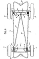
- the chassis comprises a first pair of side members 41 and 42 linked at one of their ends to respective hinges 51 and 52 placed on the telescopic shaft of the rear axle 3 and at the end opposed to hinges 61 and 62 placed on a fixed central part of the telescopic shaft of the front axle.
- the hinges placed on the front shaft are conveniently brought closer or linked to each other so that the ends of the two side members are substantially joined to each other.
- the hinges 51 and 52 placed on the rear shaft are substantially linked to opposed ends in the mobile portions of the telescopic shaft so that when the telescopic shaft itself varies its length, the angle ⁇ included between the two side members and having its vertex in the hinges 61 and 62 varies as a result.
- the chassis comprises a second pair of side members 71 and 72, arranged externally to such first pair of side members in relation to the longitudinal axis of the vehicle, linked at one of their ends to hinges 51 and 52 placed on the telescopic shaft of the rear axle which also link the ends of the first pair of side members 41 and 42 and at the end opposed to hinges 81 and 82 placed on the telescopic shaft of the front axle.
- the hinges of such second pair of side members placed on the front shaft are arranged at opposed ends in the mobile portions of the telescopic shaft.
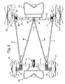
- the two front and rear axles through the mentioned telescopic shafts, are capable of varying their length, while varying the overall width of the vehicle.
- the side members, being linked to such telescopic axles through articulated hinges vary their angulation in relation to the longitudinal axis of the vehicle, do not prevent such width variation and maintain the conditions in both.
- the adjustable structure which allows for the variations of the vehicle's width either on the front axle or on the rear axle, is substantially based on five hinges, with movements at constant angles.
- the chassis is preferably made of a titanium structure and advantageously features the four powered wheels with independent suspensions.
- the motors are preferably electrical axial motors integral with the wheels.
- the steering preferably features four very limited radius knuckles, which allow for rotating the vehicle with small radii of curvature.
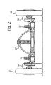
- each wheel of the vehicle is hinged onto a shaft for the transmission of the movement 25 or 35 of rotation to these and is equipped with a suspension system comprising by way of example a bracket 26 or 36 linked to the chassis of the vehicle and a shock absorber 27 or 37 linked at one of its ends to said bracket and at the opposed end to the transmission shaft 25 and 35 of the respective wheel.
- a lever 28 or 38 is hinged onto such transmission shaft, hinged in turn onto the end opposed to the respective telescopic shaft.
- each wheel may oscillate independently, by exploiting the movement of the lever which rotates around the telescopic shaft.
- the vehicle further features a first stand 97 associated with the front axle and a second stand 98 associated with the rear axle. They are in charge of lifting up the corresponding axle during the operations of variation of the dimensions of the axle itself, through the driving of the hydraulic cylinders of the telescopic shafts.
Landscapes
- Engineering & Computer Science (AREA)
- Mechanical Engineering (AREA)
- Chemical & Material Sciences (AREA)
- Combustion & Propulsion (AREA)
- Transportation (AREA)
- Vehicle Body Suspensions (AREA)
- Steering-Linkage Mechanisms And Four-Wheel Steering (AREA)
- Body Structure For Vehicles (AREA)
Abstract
Description
- The present invention concerns a variable configuration vehicle.
- In particular, the present invention refers to a variable configuration land vehicle, usable for example as a support vehicle for pleasure boats, in which the passengers of the boat itself and/or bulky loads may move on land, preferably in a port environment, when the boat is moored.
- Moreover, such vehicle may be used equally for limited transfers inside, for example, railway stations, airports and the likes.
- Small size vehicles used by service personnel are known to the state of the art, for example in railway stations, airports, etc., usually electrically powered and often having both limited locomotion capacity and space for passengers and for loads. In fact, such vehicles are often equipped with a pulling trolley on which either objects or possibly passengers are carried. An example of such vehicle is described in document
GB-A-234 967 - The Applicant has seized the problem of making a vehicle of such type which is sufficiently small and light, for example to be easily housed aboard a pleasure boat in the specially created space, and is at the same time both comfortable and large enough to accommodate people and possibly parcels or luggage.
- The Applicant has made to this aim a vehicle having a stretchable chassis which allows the vehicle in closed position to be of extremely limited dimensions and in open position to be comfortable to accommodate a plurality of passengers and parcels.
- The present invention concerns a variable configuration vehicle according to the features of claim 1.
- The characteristics and advantages of the vehicle according to the present invention will be clearer and more obvious from the following exemplifying but not limiting description of an embodiment of the invention referring to the appended figures in which:
-
figure 1 represents a schematic perspective view of the chassis of the vehicle according to the present invention; -
figure 2 represents a schematic rear view of the chassis of the vehicle according to the present invention; -
figure 3 represents a schematic side view of the chassis of the vehicle according to the present invention; -
figure 4 represents a schematic view from above of the chassis of the vehicle in closed position according to the present invention; -
figure 5 represents a schematic view from above of the chassis of the vehicle in open position according to the present invention; -
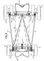
figure 6 represents a schematic view from above of the chassis of the vehicle with both positions (open and closed) visualised in particular according to the present invention. - In reference to the mentioned figures, the variable configuration vehicle according to the present invention comprises a chassis having a
front axle 2 provided at opposed ends of a pair ofwheels rear axle 3 also provided with a conventional pair ofwheels telescopic jacks - In particular, the chassis comprises a first pair of
side members respective hinges rear axle 3 and at the end opposed tohinges hinges hinges - The chassis comprises a second pair of
side members side members hinges - The hinges of such second pair of side members placed on the front shaft are arranged at opposed ends in the mobile portions of the telescopic shaft.
- The two front and rear axles, through the mentioned telescopic shafts, are capable of varying their length, while varying the overall width of the vehicle. The side members, being linked to such telescopic axles through articulated hinges vary their angulation in relation to the longitudinal axis of the vehicle, do not prevent such width variation and maintain the conditions in both.
- Therefore, the adjustable structure, which allows for the variations of the vehicle's width either on the front axle or on the rear axle, is substantially based on five hinges, with movements at constant angles.
- The chassis is preferably made of a titanium structure and advantageously features the four powered wheels with independent suspensions. The motors are preferably electrical axial motors integral with the wheels.
- The steering preferably features four very limited radius knuckles, which allow for rotating the vehicle with small radii of curvature.
- Preferably, each wheel of the vehicle is hinged onto a shaft for the transmission of the
movement bracket transmission shaft lever - The vehicle further features a
first stand 97 associated with the front axle and asecond stand 98 associated with the rear axle. They are in charge of lifting up the corresponding axle during the operations of variation of the dimensions of the axle itself, through the driving of the hydraulic cylinders of the telescopic shafts.
Claims (5)
- Variable configuration vehicle comprising a chassis having a front axle (2) provided at opposed ends of a pair of wheels (21,22) and a rear axle (3) also provided with a conventional pair of wheels (31,32) joined to each other by a plurality of substantially longitudinal side members each axle being equipped with a telescopic shaft which allows each axle to go from a closed position having a predetermined width to an open position having a width considerably greater than the width in closed position characterized in that
said chassis comprises a first pair of side members (41,42) linked at one of their ends to respective hinges (51,52) placed on the telescopic shaft of the rear axle and at the end opposed to hinges (61,62) placed on a fixed central part of the telescopic shaft of the front axle,
the hinges placed on the front shaft are brought close or linked to each other so that the ends of the two side members are substantially joined to each other and the hinges placed on the rear shaft are substantially linked to opposed ends in the mobile portions of the telescopic shaft, so that when the telescopic shaft itself varies its length, the angle (α) included between the two side members varies as a result,
such chassis comprises a second pair of side members (71,72), arranged externally to such first pair of side members in relation to the longitudinal axis of the vehicle, linked at one of their ends to the hinges (51,52) which also link the ends of the first pair of side members and at the end opposed to hinges (81,82) placed on the telescopic shaft of the front axle,
the vehicle having four powered wheels with independent suspensions and each wheel is hinged onto a shaft for the transmission of the movement (25,35) of rotation to these and is equipped with a suspension system comprising a bracket (26,36) linked to the chassis of the vehicle and a shock absorber (27,37) linked at one of its ends to said bracket and at the opposed end to the shaft for the transmission of the movement of the respective wheel. - Vehicle according to claim 1, wherein each telescopic shaft (2,3) comprises a pair of opposed telescopic jacks (23,24; 33,34).
- Vehicle according to claim 1, wherein the hinges (81,82) of such second pair of side members placed on the front shaft are arranged at opposed ends in the mobile portions of the telescopic shaft.
- Vehicle according to claim 1, wherein the chassis is made of a titanium structure.
- Vehicle according to claim 1, wherein the motors are preferably electrical axial motors integral with the wheels.
Applications Claiming Priority (1)
| Application Number | Priority Date | Filing Date | Title |
|---|---|---|---|
| IT001921A ITMI20061921A1 (en) | 2006-10-06 | 2006-10-06 | VEHICLE WITH VARIABLE CONFIGURATION |
Publications (3)
| Publication Number | Publication Date |
|---|---|
| EP1908674A1 EP1908674A1 (en) | 2008-04-09 |
| EP1908674A8 EP1908674A8 (en) | 2008-11-12 |
| EP1908674B1 true EP1908674B1 (en) | 2010-04-07 |
Family
ID=38673506
Family Applications (1)
| Application Number | Title | Priority Date | Filing Date |
|---|---|---|---|
| EP07117919A Active EP1908674B1 (en) | 2006-10-06 | 2007-10-04 | Variable configuration vehicle |
Country Status (6)
| Country | Link |
|---|---|
| EP (1) | EP1908674B1 (en) |
| AT (1) | ATE463413T1 (en) |
| DE (1) | DE602007005744D1 (en) |
| DK (1) | DK1908674T3 (en) |
| ES (1) | ES2347368T3 (en) |
| IT (1) | ITMI20061921A1 (en) |
Cited By (1)
| Publication number | Priority date | Publication date | Assignee | Title |
|---|---|---|---|---|
| CN109927784A (en) * | 2019-03-05 | 2019-06-25 | 深兰科技(上海)有限公司 | A kind of vehicle chassis and vehicle of dimension adjustable |
Families Citing this family (8)
| Publication number | Priority date | Publication date | Assignee | Title |
|---|---|---|---|---|
| CN103612541A (en) * | 2013-11-28 | 2014-03-05 | 嘉兴市凯力塑业有限公司 | Wheel distance adjusting structure on stretchable car |
| US20160010546A1 (en) | 2015-09-21 | 2016-01-14 | Electro-Motive Diesel, Inc. | Rocker cover assembly for engines |
| US11702162B2 (en) | 2021-04-28 | 2023-07-18 | Ford Global Technologies, Llc | Configurable vehicle chassis and associated methods |
| US11518206B2 (en) | 2021-04-28 | 2022-12-06 | Ford Global Technologies, Llc | Configurable vehicle frames and associated methods |
| US11938802B2 (en) | 2021-04-28 | 2024-03-26 | Ford Global Technologies, Llc | Electric motorized wheel assemblies |
| US11866095B2 (en) | 2021-04-28 | 2024-01-09 | Ford Global Technologies, Llc | Multi-position wheel assembly mounts |
| US11807302B2 (en) * | 2021-04-28 | 2023-11-07 | Ford Global Technologies, Llc | Methods and apparatus for scalable vehicle platforms |
| US11858571B2 (en) | 2021-04-28 | 2024-01-02 | Ford Global Technologies, Llc | Vehicle chassis with interchangeable performance packages and related methods |
Family Cites Families (4)
| Publication number | Priority date | Publication date | Assignee | Title |
|---|---|---|---|---|
| US3854747A (en) * | 1974-03-28 | 1974-12-17 | J Johnston | Laterally and longitudinally extensible truck |
| FR2735744B1 (en) * | 1995-06-22 | 1997-09-05 | Bernard Michel | VERSATILE CARRYING DEVICE FOR TRAILER |
| US5560444A (en) * | 1995-06-30 | 1996-10-01 | Hydra-Slide Corporation | Expandable trailer having a position locking feature |
| GB2311967A (en) * | 1996-04-10 | 1997-10-15 | Bateman Engineering Ltd | A variable-track, four wheel steering agricultural vehicle with active suspension |
-
2006
- 2006-10-06 IT IT001921A patent/ITMI20061921A1/en unknown
-
2007
- 2007-10-04 AT AT07117919T patent/ATE463413T1/en not_active IP Right Cessation
- 2007-10-04 ES ES07117919T patent/ES2347368T3/en active Active
- 2007-10-04 EP EP07117919A patent/EP1908674B1/en active Active
- 2007-10-04 DK DK07117919.6T patent/DK1908674T3/en active
- 2007-10-04 DE DE602007005744T patent/DE602007005744D1/en active Active
Cited By (1)
| Publication number | Priority date | Publication date | Assignee | Title |
|---|---|---|---|---|
| CN109927784A (en) * | 2019-03-05 | 2019-06-25 | 深兰科技(上海)有限公司 | A kind of vehicle chassis and vehicle of dimension adjustable |
Also Published As
| Publication number | Publication date |
|---|---|
| ITMI20061921A1 (en) | 2008-04-07 |
| DE602007005744D1 (en) | 2010-05-20 |
| ES2347368T3 (en) | 2010-10-28 |
| EP1908674A1 (en) | 2008-04-09 |
| HK1115564A1 (en) | 2008-12-05 |
| EP1908674A8 (en) | 2008-11-12 |
| DK1908674T3 (en) | 2010-08-09 |
| ATE463413T1 (en) | 2010-04-15 |
Similar Documents
| Publication | Publication Date | Title |
|---|---|---|
| EP1908674B1 (en) | Variable configuration vehicle | |
| US9145168B2 (en) | Laterally tiltable, multitrack vehicle | |
| US9283989B2 (en) | Laterally tiltable, multitrack vehicle | |
| US11745793B2 (en) | Bus steering system | |
| US20170291658A1 (en) | Modular transporter | |
| EP0931684B1 (en) | Electrically driven vehicle | |
| US20110272900A1 (en) | Central multidirectional drive transmission system | |
| US20190176921A1 (en) | Vehicle having three or more tilting wheels with reactive constraint suspension | |
| CN203921058U (en) | A kind of light weight tricycle | |
| JP4541201B2 (en) | Car | |
| EP1697200B1 (en) | Driven steer carriage | |
| CN202463491U (en) | Articulated structure of articulated dumper | |
| US7108086B2 (en) | All wheel drive utility vehicle with bogey beam suspension | |
| US1093131A (en) | Load-supporting means for carrying-wheels. | |
| HK1115564B (en) | Variable configuration vehicle | |
| EP3068649B1 (en) | Appliance with motorized wheels | |
| CN117141628B (en) | Tiltable suspension balance mechanism and tiltable suspension vehicle | |
| CA2129851A1 (en) | Vehicle with retractable wheel | |
| KR101955409B1 (en) | Cornering Anti-roll Chair System for Kart | |
| FR2936212A1 (en) | TRANSPARENT DEVICE WITH VARIABLE BODY FOR TUNNEL | |
| US3899039A (en) | Bus having a separate wheeled motive power unit | |
| RU2331542C1 (en) | Wheeled-walking vehicle | |
| US20230027448A1 (en) | Frame Steered Vehicle | |
| JPS63116912A (en) | Steerable wheel capable of being changed into driving wheel and application to amphibian motor car | |
| CN214164715U (en) | Chassis assembly |
Legal Events
| Date | Code | Title | Description |
|---|---|---|---|
| PUAI | Public reference made under article 153(3) epc to a published international application that has entered the european phase |
Free format text: ORIGINAL CODE: 0009012 |
|
| AK | Designated contracting states |
Kind code of ref document: A1 Designated state(s): AT BE BG CH CY CZ DE DK EE ES FI FR GB GR HU IE IS IT LI LT LU LV MC MT NL PL PT RO SE SI SK TR |
|
| AX | Request for extension of the european patent |
Extension state: AL BA HR MK RS |
|
| 17P | Request for examination filed |
Effective date: 20080925 |
|
| RAP1 | Party data changed (applicant data changed or rights of an application transferred) |
Owner name: MAURIZI, PIERLUIGI Owner name: PLATANIA, MICHELE Owner name: UNIVERSITA DEGLI STUDI DI GENOVA - DIPARTIMENTO DI Owner name: POLITECNICO DI MILANO Owner name: OTO MELARA S.P.A. |
|
| REG | Reference to a national code |
Ref country code: HK Ref legal event code: DE Ref document number: 1115564 Country of ref document: HK |
|
| 17Q | First examination report despatched |
Effective date: 20081106 |
|
| AKX | Designation fees paid |
Designated state(s): AT BE BG CH CY CZ DE DK EE ES FI FR GB GR HU IE IS IT LI LT LU LV MC MT NL PL PT RO SE SI SK TR |
|
| AXX | Extension fees paid |
Extension state: BA Payment date: 20080925 Extension state: AL Payment date: 20080925 Extension state: HR Payment date: 20080925 |
|
| GRAP | Despatch of communication of intention to grant a patent |
Free format text: ORIGINAL CODE: EPIDOSNIGR1 |
|
| GRAS | Grant fee paid |
Free format text: ORIGINAL CODE: EPIDOSNIGR3 |
|
| GRAA | (expected) grant |
Free format text: ORIGINAL CODE: 0009210 |
|
| AK | Designated contracting states |
Kind code of ref document: B1 Designated state(s): AT BE BG CH CY CZ DE DK EE ES FI FR GB GR HU IE IS IT LI LT LU LV MC MT NL PL PT RO SE SI SK TR |
|
| AX | Request for extension of the european patent |
Extension state: AL BA HR |
|
| REG | Reference to a national code |
Ref country code: GB Ref legal event code: FG4D |
|
| REG | Reference to a national code |
Ref country code: CH Ref legal event code: EP |
|
| REG | Reference to a national code |
Ref country code: IE Ref legal event code: FG4D |
|
| REF | Corresponds to: |
Ref document number: 602007005744 Country of ref document: DE Date of ref document: 20100520 Kind code of ref document: P |
|
| REG | Reference to a national code |
Ref country code: NL Ref legal event code: T3 |
|
| REG | Reference to a national code |
Ref country code: SE Ref legal event code: TRGR |
|
| REG | Reference to a national code |
Ref country code: DK Ref legal event code: T3 |
|
| PG25 | Lapsed in a contracting state [announced via postgrant information from national office to epo] |
Ref country code: SI Free format text: LAPSE BECAUSE OF FAILURE TO SUBMIT A TRANSLATION OF THE DESCRIPTION OR TO PAY THE FEE WITHIN THE PRESCRIBED TIME-LIMIT Effective date: 20100407 |
|
| LTIE | Lt: invalidation of european patent or patent extension |
Effective date: 20100407 |
|
| REG | Reference to a national code |
Ref country code: ES Ref legal event code: FG2A Ref document number: 2347368 Country of ref document: ES Kind code of ref document: T3 |
|
| PG25 | Lapsed in a contracting state [announced via postgrant information from national office to epo] |
Ref country code: LT Free format text: LAPSE BECAUSE OF FAILURE TO SUBMIT A TRANSLATION OF THE DESCRIPTION OR TO PAY THE FEE WITHIN THE PRESCRIBED TIME-LIMIT Effective date: 20100407 |
|
| REG | Reference to a national code |
Ref country code: CH Ref legal event code: NV Representative=s name: ROTTMANN, ZIMMERMANN + PARTNER AG |
|
| REG | Reference to a national code |
Ref country code: HK Ref legal event code: GR Ref document number: 1115564 Country of ref document: HK |
|
| PG25 | Lapsed in a contracting state [announced via postgrant information from national office to epo] |
Ref country code: IS Free format text: LAPSE BECAUSE OF FAILURE TO SUBMIT A TRANSLATION OF THE DESCRIPTION OR TO PAY THE FEE WITHIN THE PRESCRIBED TIME-LIMIT Effective date: 20100807 Ref country code: FI Free format text: LAPSE BECAUSE OF FAILURE TO SUBMIT A TRANSLATION OF THE DESCRIPTION OR TO PAY THE FEE WITHIN THE PRESCRIBED TIME-LIMIT Effective date: 20100407 Ref country code: AT Free format text: LAPSE BECAUSE OF FAILURE TO SUBMIT A TRANSLATION OF THE DESCRIPTION OR TO PAY THE FEE WITHIN THE PRESCRIBED TIME-LIMIT Effective date: 20100407 Ref country code: LV Free format text: LAPSE BECAUSE OF FAILURE TO SUBMIT A TRANSLATION OF THE DESCRIPTION OR TO PAY THE FEE WITHIN THE PRESCRIBED TIME-LIMIT Effective date: 20100407 |
|
| PG25 | Lapsed in a contracting state [announced via postgrant information from national office to epo] |
Ref country code: CY Free format text: LAPSE BECAUSE OF FAILURE TO SUBMIT A TRANSLATION OF THE DESCRIPTION OR TO PAY THE FEE WITHIN THE PRESCRIBED TIME-LIMIT Effective date: 20100526 Ref country code: PL Free format text: LAPSE BECAUSE OF FAILURE TO SUBMIT A TRANSLATION OF THE DESCRIPTION OR TO PAY THE FEE WITHIN THE PRESCRIBED TIME-LIMIT Effective date: 20100407 |
|
| PG25 | Lapsed in a contracting state [announced via postgrant information from national office to epo] |
Ref country code: PT Free format text: LAPSE BECAUSE OF FAILURE TO SUBMIT A TRANSLATION OF THE DESCRIPTION OR TO PAY THE FEE WITHIN THE PRESCRIBED TIME-LIMIT Effective date: 20100809 Ref country code: EE Free format text: LAPSE BECAUSE OF FAILURE TO SUBMIT A TRANSLATION OF THE DESCRIPTION OR TO PAY THE FEE WITHIN THE PRESCRIBED TIME-LIMIT Effective date: 20100407 |
|
| PLBE | No opposition filed within time limit |
Free format text: ORIGINAL CODE: 0009261 |
|
| STAA | Information on the status of an ep patent application or granted ep patent |
Free format text: STATUS: NO OPPOSITION FILED WITHIN TIME LIMIT |
|
| PG25 | Lapsed in a contracting state [announced via postgrant information from national office to epo] |
Ref country code: RO Free format text: LAPSE BECAUSE OF FAILURE TO SUBMIT A TRANSLATION OF THE DESCRIPTION OR TO PAY THE FEE WITHIN THE PRESCRIBED TIME-LIMIT Effective date: 20100407 Ref country code: CZ Free format text: LAPSE BECAUSE OF FAILURE TO SUBMIT A TRANSLATION OF THE DESCRIPTION OR TO PAY THE FEE WITHIN THE PRESCRIBED TIME-LIMIT Effective date: 20100407 Ref country code: SK Free format text: LAPSE BECAUSE OF FAILURE TO SUBMIT A TRANSLATION OF THE DESCRIPTION OR TO PAY THE FEE WITHIN THE PRESCRIBED TIME-LIMIT Effective date: 20100407 |
|
| 26N | No opposition filed |
Effective date: 20110110 |
|
| PG25 | Lapsed in a contracting state [announced via postgrant information from national office to epo] |
Ref country code: IT Free format text: LAPSE BECAUSE OF FAILURE TO SUBMIT A TRANSLATION OF THE DESCRIPTION OR TO PAY THE FEE WITHIN THE PRESCRIBED TIME-LIMIT Effective date: 20100407 |
|
| PG25 | Lapsed in a contracting state [announced via postgrant information from national office to epo] |
Ref country code: GR Free format text: LAPSE BECAUSE OF FAILURE TO SUBMIT A TRANSLATION OF THE DESCRIPTION OR TO PAY THE FEE WITHIN THE PRESCRIBED TIME-LIMIT Effective date: 20100708 |
|
| PG25 | Lapsed in a contracting state [announced via postgrant information from national office to epo] |
Ref country code: MC Free format text: LAPSE BECAUSE OF NON-PAYMENT OF DUE FEES Effective date: 20101031 |
|
| REG | Reference to a national code |
Ref country code: CH Ref legal event code: PFA Owner name: POLITECNICO DI MILANO Free format text: POLITECNICO DI MILANO#PIAZZA LEONARDO DA VINCI 32#20133 MILANO (IT) $ PLATANIA, MICHELE#VIA LUCIANO MANARA 43#00153 ROME (IT) $ MAURIZI, PIERLUIGI#VIA DEL MORO 23#00153 ROME (IT) $ UNIVERSITA DEGLI STUDI DI GENOVA - DIPARTIMENTO DI SCIENZE PER L'ARCHITETTURA#VIA BALBI 5#16126 GENOVA (IT) $ OTO MELARA S.P.A. CON UNICO SOCIO#VIA VALDILOCCHI, 15#19136 LA SPEZIA (IT) -TRANSFER TO- POLITECNICO DI MILANO#PIAZZA LEONARDO DA VINCI 32#20133 MILANO (IT) $ PLATANIA, MICHELE#VIA LUCIANO MANARA 43#00153 ROME (IT) $ MAURIZI, PIERLUIGI#VIA DEL MORO 23#00153 ROME (IT) $ UNIVERSITA DEGLI STUDI DI GENOVA - DIPARTIMENTO DI SCIENZE PER L'ARCHITETTURA#VIA BALBI 5#16126 GENOVA (IT) $ OTO MELARA S.P.A. CON |
|
| PG25 | Lapsed in a contracting state [announced via postgrant information from national office to epo] |
Ref country code: IE Free format text: LAPSE BECAUSE OF NON-PAYMENT OF DUE FEES Effective date: 20101004 |
|
| PG25 | Lapsed in a contracting state [announced via postgrant information from national office to epo] |
Ref country code: MT Free format text: LAPSE BECAUSE OF FAILURE TO SUBMIT A TRANSLATION OF THE DESCRIPTION OR TO PAY THE FEE WITHIN THE PRESCRIBED TIME-LIMIT Effective date: 20100407 |
|
| PG25 | Lapsed in a contracting state [announced via postgrant information from national office to epo] |
Ref country code: LU Free format text: LAPSE BECAUSE OF NON-PAYMENT OF DUE FEES Effective date: 20101004 Ref country code: HU Free format text: LAPSE BECAUSE OF FAILURE TO SUBMIT A TRANSLATION OF THE DESCRIPTION OR TO PAY THE FEE WITHIN THE PRESCRIBED TIME-LIMIT Effective date: 20101008 Ref country code: BG Free format text: LAPSE BECAUSE OF FAILURE TO SUBMIT A TRANSLATION OF THE DESCRIPTION OR TO PAY THE FEE WITHIN THE PRESCRIBED TIME-LIMIT Effective date: 20100407 |
|
| PG25 | Lapsed in a contracting state [announced via postgrant information from national office to epo] |
Ref country code: TR Free format text: LAPSE BECAUSE OF FAILURE TO SUBMIT A TRANSLATION OF THE DESCRIPTION OR TO PAY THE FEE WITHIN THE PRESCRIBED TIME-LIMIT Effective date: 20100407 |
|
| PG25 | Lapsed in a contracting state [announced via postgrant information from national office to epo] |
Ref country code: BG Free format text: LAPSE BECAUSE OF FAILURE TO SUBMIT A TRANSLATION OF THE DESCRIPTION OR TO PAY THE FEE WITHIN THE PRESCRIBED TIME-LIMIT Effective date: 20100707 |
|
| PGFP | Annual fee paid to national office [announced via postgrant information from national office to epo] |
Ref country code: DK Payment date: 20141010 Year of fee payment: 8 |
|
| PGFP | Annual fee paid to national office [announced via postgrant information from national office to epo] |
Ref country code: CH Payment date: 20141014 Year of fee payment: 8 Ref country code: SE Payment date: 20141013 Year of fee payment: 8 |
|
| PGFP | Annual fee paid to national office [announced via postgrant information from national office to epo] |
Ref country code: BE Payment date: 20141013 Year of fee payment: 8 |
|
| PGFP | Annual fee paid to national office [announced via postgrant information from national office to epo] |
Ref country code: GB Payment date: 20150930 Year of fee payment: 9 |
|
| PGFP | Annual fee paid to national office [announced via postgrant information from national office to epo] |
Ref country code: NL Payment date: 20151012 Year of fee payment: 9 |
|
| REG | Reference to a national code |
Ref country code: DK Ref legal event code: EBP Effective date: 20151031 |
|
| REG | Reference to a national code |
Ref country code: SE Ref legal event code: EUG Ref country code: CH Ref legal event code: PL |
|
| PG25 | Lapsed in a contracting state [announced via postgrant information from national office to epo] |
Ref country code: CH Free format text: LAPSE BECAUSE OF NON-PAYMENT OF DUE FEES Effective date: 20151031 Ref country code: LI Free format text: LAPSE BECAUSE OF NON-PAYMENT OF DUE FEES Effective date: 20151031 |
|
| PG25 | Lapsed in a contracting state [announced via postgrant information from national office to epo] |
Ref country code: SE Free format text: LAPSE BECAUSE OF NON-PAYMENT OF DUE FEES Effective date: 20151005 |
|
| REG | Reference to a national code |
Ref country code: FR Ref legal event code: PLFP Year of fee payment: 10 |
|
| PG25 | Lapsed in a contracting state [announced via postgrant information from national office to epo] |
Ref country code: DK Free format text: LAPSE BECAUSE OF NON-PAYMENT OF DUE FEES Effective date: 20151031 |
|
| REG | Reference to a national code |
Ref country code: NL Ref legal event code: MM Effective date: 20161101 |
|
| GBPC | Gb: european patent ceased through non-payment of renewal fee |
Effective date: 20161004 |
|
| PG25 | Lapsed in a contracting state [announced via postgrant information from national office to epo] |
Ref country code: GB Free format text: LAPSE BECAUSE OF NON-PAYMENT OF DUE FEES Effective date: 20161004 Ref country code: BE Free format text: LAPSE BECAUSE OF NON-PAYMENT OF DUE FEES Effective date: 20151031 |
|
| PG25 | Lapsed in a contracting state [announced via postgrant information from national office to epo] |
Ref country code: NL Free format text: LAPSE BECAUSE OF NON-PAYMENT OF DUE FEES Effective date: 20161101 |
|
| REG | Reference to a national code |
Ref country code: FR Ref legal event code: PLFP Year of fee payment: 11 |
|
| REG | Reference to a national code |
Ref country code: DE Ref legal event code: R082 Ref document number: 602007005744 Country of ref document: DE Representative=s name: MAIWALD GMBH, DE Ref country code: DE Ref legal event code: R082 Ref document number: 602007005744 Country of ref document: DE Representative=s name: MAIWALD PATENTANWALTS- UND RECHTSANWALTSGESELL, DE |
|
| REG | Reference to a national code |
Ref country code: FR Ref legal event code: PLFP Year of fee payment: 12 |
|
| PGFP | Annual fee paid to national office [announced via postgrant information from national office to epo] |
Ref country code: DE Payment date: 20251020 Year of fee payment: 19 |
|
| PGFP | Annual fee paid to national office [announced via postgrant information from national office to epo] |
Ref country code: FR Payment date: 20251024 Year of fee payment: 19 |
|
| PGFP | Annual fee paid to national office [announced via postgrant information from national office to epo] |
Ref country code: ES Payment date: 20251114 Year of fee payment: 19 |