EP1908596B1 - Ink cartridges - Google Patents
Ink cartridges Download PDFInfo
- Publication number
- EP1908596B1 EP1908596B1 EP20070019580 EP07019580A EP1908596B1 EP 1908596 B1 EP1908596 B1 EP 1908596B1 EP 20070019580 EP20070019580 EP 20070019580 EP 07019580 A EP07019580 A EP 07019580A EP 1908596 B1 EP1908596 B1 EP 1908596B1
- Authority
- EP
- European Patent Office
- Prior art keywords
- ink
- opening
- valve
- chamber
- accommodating chamber
- Prior art date
- Legal status (The legal status is an assumption and is not a legal conclusion. Google has not performed a legal analysis and makes no representation as to the accuracy of the status listed.)
- Ceased
Links
- 238000004891 communication Methods 0.000 claims description 42
- 239000012530 fluid Substances 0.000 claims description 29
- 239000000976 ink Substances 0.000 description 386
- 238000001514 detection method Methods 0.000 description 15
- 230000000903 blocking effect Effects 0.000 description 12
- 238000000034 method Methods 0.000 description 8
- 239000000463 material Substances 0.000 description 7
- 229920003002 synthetic resin Polymers 0.000 description 7
- 239000000057 synthetic resin Substances 0.000 description 7
- 230000003287 optical effect Effects 0.000 description 6
- 230000002093 peripheral effect Effects 0.000 description 6
- 239000003086 colorant Substances 0.000 description 4
- 230000007423 decrease Effects 0.000 description 4
- 230000005484 gravity Effects 0.000 description 4
- 210000000078 claw Anatomy 0.000 description 3
- 238000001746 injection moulding Methods 0.000 description 3
- 239000013013 elastic material Substances 0.000 description 2
- 239000000203 mixture Substances 0.000 description 2
- 239000000049 pigment Substances 0.000 description 2
- 229920005989 resin Polymers 0.000 description 2
- 239000011347 resin Substances 0.000 description 2
- 238000005452 bending Methods 0.000 description 1
- 230000008878 coupling Effects 0.000 description 1
- 238000010168 coupling process Methods 0.000 description 1
- 238000005859 coupling reaction Methods 0.000 description 1
- -1 e.g. Substances 0.000 description 1
- 230000008020 evaporation Effects 0.000 description 1
- 238000001704 evaporation Methods 0.000 description 1
- 239000011796 hollow space material Substances 0.000 description 1
- 239000007769 metal material Substances 0.000 description 1
- 238000011144 upstream manufacturing Methods 0.000 description 1
Images


Classifications
-
- B—PERFORMING OPERATIONS; TRANSPORTING
- B41—PRINTING; LINING MACHINES; TYPEWRITERS; STAMPS
- B41J—TYPEWRITERS; SELECTIVE PRINTING MECHANISMS, i.e. MECHANISMS PRINTING OTHERWISE THAN FROM A FORME; CORRECTION OF TYPOGRAPHICAL ERRORS
- B41J2/00—Typewriters or selective printing mechanisms characterised by the printing or marking process for which they are designed
- B41J2/005—Typewriters or selective printing mechanisms characterised by the printing or marking process for which they are designed characterised by bringing liquid or particles selectively into contact with a printing material
- B41J2/01—Ink jet
- B41J2/17—Ink jet characterised by ink handling
- B41J2/175—Ink supply systems ; Circuit parts therefor
- B41J2/17596—Ink pumps, ink valves
-
- B—PERFORMING OPERATIONS; TRANSPORTING
- B41—PRINTING; LINING MACHINES; TYPEWRITERS; STAMPS
- B41J—TYPEWRITERS; SELECTIVE PRINTING MECHANISMS, i.e. MECHANISMS PRINTING OTHERWISE THAN FROM A FORME; CORRECTION OF TYPOGRAPHICAL ERRORS
- B41J2/00—Typewriters or selective printing mechanisms characterised by the printing or marking process for which they are designed
- B41J2/005—Typewriters or selective printing mechanisms characterised by the printing or marking process for which they are designed characterised by bringing liquid or particles selectively into contact with a printing material
- B41J2/01—Ink jet
- B41J2/17—Ink jet characterised by ink handling
- B41J2/175—Ink supply systems ; Circuit parts therefor
- B41J2/17503—Ink cartridges
- B41J2/17556—Means for regulating the pressure in the cartridge
Definitions
- the present invention relates generally to ink cartridges.
- the present invention is directed towards ink cartridges which may be used in combination with ink jet printers.
- a known inkjet printer has a recording head from which ink is discharged onto a sheet of paper to form images on the sheet of paper.
- the known inkjet printer also has an ink tank storing ink therein.
- the recording head and the ink tank are in fluid communication with each other via an ink supply path formed by a tube.
- the known inkjet printer also has a pump provided in the ink supply path between the ink tank and the recording head.
- the pump is configured to supply ink from the ink tank to the recording head and also return ink from the recording head to the ink tank.
- air bubbles which may have been trapped in the recording head or the tube, or both, flow into the ink tank. Air bubbles are separated from ink in an ink chamber provided in ink tank, Thus, air bubbles are removed from recording head or the tube, or both.
- Another known inkjet printer has an ink tank, and the ink tank has a valve configured to allow and prevent fluid communication between the ink tank and a recording head.
- the valve is accommodated in a valve accommodating chamber provided in the ink tank.
- a corresponding example is shown in US-A-2005/0168540 .
- ink in the valve accommodating chamber also needs to be returned to the ink chamber as well as ink in the recording head and the tube. This is because, if some of the ink, which was in the recording head and the tube, is left in the valve accommodating portion, air bubbles trapped in the ink may adhere to the valve, which may disturb the movement of the valve. Moreover, the air bubbles adhering to the valve may return into the tube and the recording head when ink is supplied from the ink tank to the recording head. Nevertheless, in order to return ink in the valve accommodating chamber to the ink chamber as well as ink in the recording head and the tube, a more powerful pump having relatively high capacity may be needed.
- a technical advantage of the present invention is to separate air bubbles from ink and to prevent air bubbles from staying in the valve accommodating chamber.
- an ink cartridge comprises an ink chamber; a side wall having a first opening formed therethrough; a valve accommodating chamber configured to be in fluid communication with an outside of the ink cartridge via the first opening; a valve accommodated in the valve accommodating chamber, wherein the valve is configured to move in the valve accommodating chamber to allow and prevent the fluid communication between the valve accommodating chamber and the outside of the ink cartridge via the first opening; and a particular wall extending from the side wall toward the ink chamber, the particular wall defining the valve accommodating chamber, wherein the particular wall has a second opening formed therethrough, and the valve accommodating chamber is configured to be in fluid communication with the ink chamber via the second opening.
- the second opening is positioned above each of the valve accommodating chamber and the first opening.
- the second opening were positioned below the valve accommodating chamber and the first opening, the amount of ink corresponding to ink in the valve accommodating chamber, a tube, and a recording head would be needed to be drawn into the ink chamber to remove air bubbles trapped in tube and the recording head. Nevertheless, the second opening is positioned above each of the valve accommodating chamber and the first opening, only the amount of ink corresponding to the tube and the recording head are needed to be drawn into the ink chamber. In this case, ink and air bubbles may stay in the valve accommodating chamber. Nevertheless, the buoyancy acting on the air bubbles moves up the air bubbles, and the air bubbles go out of the valve accommodating chamber via the second opening. With this ink cartridge, there is no need to provide a pump having relatively high capacity.
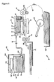
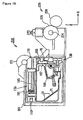
- Figure 1 is a simplified cross sectional view of an ink-jet recording apparatus, according to an embodiment of the present invention.
- Figure 2(a) is an expanded cross sectional view of a recording unit when a sub ink tank is not in fluid communication with the atmosphere.
- Figure 2(b) is an expanded cross sectional view of the recording unit when the sub ink tank is in fluid communication with the atmosphere.
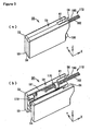
- Figure 3(a) is a perspective view of an ink cartridge, according to an embodiment of the present invention, with a case assembled.
- Figure 3(b) is a perspective view of the ink cartridge with the case disassembled.
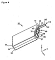
- Figure 4 is a perspective view of the ink cartridge from a different angle.
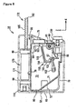
- Figure 5 is a perspective view depicting an internal structure of the ink cartridge.
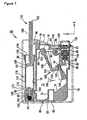
- Figure 6 is a side view of the internal structure seen along an arrow VI in Figure 5 .
- Figure 7 is a cross sectional view of the ink cartridge taken along the VII-VII line in Figure 5 .
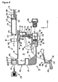
- Figure 8 is an exploded cross sectional view of the ink cartridge.
- Figure 9 is a partial cross sectional view taken along the IX-IX line in Figure 8 .
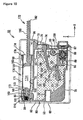
- Figure 10 is a cross sectional view of the ink cartridge when the ink cartridge is filled with a predetermined amount of ink.
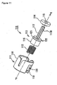
- Figure 11 is an exploded view of an air communication portion.
- Figure 12(a) is a partial cross sectional view of the air communication portion when a valve is positioned at P1.
- Figure 12(b) is a partial cross sectional view of the air communication portion when the valve is positioned at P2.
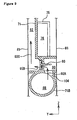
- Figure 13 is a partial cross sectional view of a pump
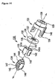
- Figure 14 is an exploded view of an ink supply portion.
- Figure 15 is a partial cross sectional.view of the ink supply portion.
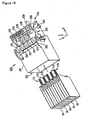
- Figure 16 is a perspective view of a cartridge mounting portion and the ink cartridges when the ink cartridges are not mounted to the cartridge mounting portion.
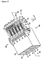
- Figure 17 is a perspective view of the cartridge mounting portion and the ink cartridges when the ink cartridges are mounted to the cartridge mounting portion.
- Figure 18 is a side view of the cartridge mounting portion seen along an arrow XVIII in Figure 17 .
- Figure 19 is a cross sectional view of the cartridge mounting portion and the ink cartridge taken along XIX-XIX line in Figure 17 .
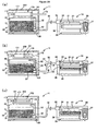
- Figures 20(a) to 20(c) are schematics depicting an ink supply process and an ink draw process.
- an inkjet recording device 10 is configured to record color images or monochrome images on a recording medium e.g. a sheet of paper with a black ink or several colors of inks, for example, with five colors of inks, e.g. cyan ink, magenta ink, yellow ink, dye-based black ink, and pigment-based black ink.
- Inkjet recording device 10 comprises a paper feed device 12, a convey device 13, a recording unit 14, an ink supply system 11, a paper tray 16, and a discharge tray 17.
- Paper tray 16 is configured to accommodate sheets of paper and the sheets are fed by the paper feed device 12 to a paper path 18.
- Paper path 18 is formed in a 90-degree-rotated "U" shape.
- Convey device 13 is provided along paper path 18.
- Convey device 13 comprises a pair of convey rollers 13A, a pair of discharge rollers 13B, and a platen 19.
- Convey rollers 13A are positioned on the upstream side of recording unit 14 in paper path 18, and discharge rollers 13B are positioned on the downstream side of recording unit 14 in paper path 18.
- Convey rollers 13A are configured to convey the sheet fed by paper feed device 12 to platen 19.
- Recording unit 14 is positioned directly above platen 19.
- Recording unit 14 is configured to record images on the sheet passing over platen 19.
- Discharge rollers 13B are configured to start nipping and conveying the sheet when the leading edge of the sheet reaches discharge rollers 13B.
- Both convey rollers 13A and discharge rollers 13B are configured to convey the sheet until the trailing edge of the sheet passes between convey rollers 13A. After the sheet has passed between convey rollers 13A, the sheet is conveyed by only discharge rollers 13B.
- Discharge tray 17 is positioned at the most downstream of paper path 18.
- Discharge rollers 13B are configured to discharge the sheet, on which the image is recorded, to discharge tray 17.
- Recording unit 14 comprises a carriage 30, at least one sub ink tank 21, a head control board 27, and a recording head 26.
- Carriage 30 is supported by rails slidably thereon and is configured to slide in the back-and-forth direction of Figure 1 .
- Sub ink tank 21 is configured to store ink to be supplied to recording head 26.
- Five sub ink tanks 21 are provided corresponding to the five colors of inks respectively for example.
- Recording head 26 comprises a plurality of nozzles 28 through which ink is ejected toward the sheet of paper based on image signals input to head control board 27.
- Inkjet recording device 10 comprises a main controller configured to perform an overall control of inkjet recording device 10, and the image signals are output from the main controller and input to head control board 27.
- Carriage 30 comprises a side face, and at least one joint 33 is provided at the side face of carriage 30. At least one flexible tube 32 is connected to the at least one joint 33. Five tubes 32 and five joints 33 are provided corresponding to the five colors of inks respectively for example. A path 34 is provided in carriage 30 extending from joint 33 to the bottom of sub ink tank 21.
- valve mechanism 37 is provided in carriage 30, and valve mechanism 37 comprises a cylinder 39, which is in fluid communication with sub ink tank 21, a coil spring 41, and a piston 40.
- Coil spring 41 and piston 40 are accommodated in cylinder 39.
- Cylinder 39 comprises a bottom wall and has an opening 42 formed through the bottom wall of cylinder 39.
- Coil spring 41 is compressed and urges piston 40 in a direction that piston 40 closes opening 42.
- a rod 43 extends from piston 40 through opening 42 to the outside of cylinder 39.
- piston 40 is configured to move within cylinder 39 against the urging force of coil spring 41 to open opening 42 when a force is applied to rod 43 in a direction opposite the direction of the urging force of coil spring 41.
- the inside of the sub ink tank 21 is configured to communicate with the atmosphere via cylinder 39 and opening 42 when opening 42 is opened.
- opening 42 is made open.
- opening 42 is made closed to prevent evaporation of ink.
- ink supply system 11 comprises a cartridge mounting portion 200, at least one ink cartridge 50, at least one flexible tube 32, and at least one sub ink tank 21.
- Cartridge mounting portion 200 is configured to detachably mount at least one ink cartridge 50 therein.
- Ink cartridge 50 comprises a main ink tank 70 for storing ink.
- Main ink tank 70 and sub ink tank 21 are configured to be in fluid communication with each other via tube 32.
- Five tubes 32 are connected to five main ink tanks 70 of five ink cartridges 50 and five sub ink tanks 21 respectively for example. Ink flows between main ink tank 70 and sub ink tank 21 bi-directionally via tube 32.
- Tube 32 is made of at least one flexible synthetic resin, Tube 32 therefore is configured to be flexed and follow the movement of carriage 30 when carriage 30 reciprocates.
- ink in sub ink tank 21 and tube 32 When ink in sub ink tank 21 and tube 32 is returned to main ink tank 30, air bubbles trapped in sub ink tank 21 and tube 32 may also be transferred to main ink tank 30 along with the ink, and the air bubbles may be separated from ink inside main ink tank 30. After that, ink may be supplied from main ink tank 70 to sub ink tank 21. Consequently ink in sub ink tank 21 is replaced with ink in main ink tank 70, and ink in sub ink tank 21 and ink in main ink tank 70 are mixed, Thus, the viscosity of ink may be equalized by the mixture.
- ink cartridge 50 comprises a case 52.
- Case 52 has a rectangular parallelepiped shape having a width in Y-axis direction in Figures 3 to 5 , a height in Z-axis direction in Figures 3 to 9 , and a depth in X-axis direction in Figures 3 to 9 .
- the height is greater than the width, and the depth is greater than the height.
- X-axis direction is parallel with a direction in which ink cartridge 50 is mounted into cartridge mounting portion 200.
- X-Y plane which is defined by X axis and Y axis is a horizontal plane.
- X-axis, Y-axis, and Z-axis are perpendicular to one another.
- Case 52 comprises a first case member 53 and a second case member 54. Case 52 is configured to be selectively disassembled into first case member 53 and second case member 54 along X-axis direction.
- the shape of first case member 53 is substantially the same as the shape of second case member 54.
- Each of first case member 53 and second case member 54 is made of at least one synthetic resin, and is manufactured by injection molding.
- Case 52 comprises a top face 59 and a front face 60.
- Front face 60 has a first end and a second end, and top face is connected to the first end of front face 60.
- An opening 56 is formed through top face 59 and extends to front face 60. Opening 56 is defined by cut-out portions 61 formed in first case member 53 and second case member 54 respectively.
- a portion of a rod 182, which is described later, is configured to be positioned in opening 56, and rod 182 is configured to extend from front face 60.
- An opening 57 is formed through front face 60 adjacent to the second end of front face 60. Opening 57 is defined by semi-circular cut-out portions formed in first case member 53 and second case member 54 respectively.
- An ink supply portion 130 extends from the inside of case 52 to the outside of case 52 through opening 57.
- An opening 58 is formed through front face 60 between opening 56 and opening 57. Opening 58 is defined by rectangular cut-out portions 62 formed in first case member 53 and second case member 54 respectively.
- a detection portion 75 is positioned in the inside of case 52 and exposed to the outside of case 52 through opening 58.
- ink cartridge 50 comprises, main ink tank 70, a pump 170, an air communication portion 110, and ink supply portion 130. At least a portion of each of main ink tank 70, pump 170, air communication portion 110, and ink supply portion 130 is positioned in case 52. Each of main ink tank 70, pump 170, air communication portion 110, and ink supply portion 130 is made of at least one synthetic resin.
- Main ink tank 70 is substantially enclosed in case 52.
- Main ink tank 70 has a width in Y-axis direction, a height in Z-axis direction, and a depth in X-axis direction.
- the height of main ink tank 70 is greater than the width of main ink tank 70, and the depth of main ink tank 70 is greater than the height.
- Main ink tank 70 comprises a translucent frame 71 and translucent films 81 welded to both side faces of frame 71.
- Frame 71 and films 81 define an ink chamber 73 therein for storing ink. Films 81 are omitted in the drawings.
- main tank 70 comprises a cylindrical ink fill portion 72, and ink fill portion 72 is integrally formed with frame 71.
- An ink fill opening 82 is formed through a rear face 80 of main tank 70.
- Ink fill portion 72 extends from ink fill opening 82 toward ink chamber 73 in X-axis direction.
- Ink chamber 73 is configured to be filled with a predetermined amount of ink via ink fill opening 82 and ink fill portion 72.
- the predetermined amount of ink may be about 80% of a maximum capacity of ink chamber 73.
- Ink chamber 73 comprises an upper portion closer to air communication portion 110 and a lower portion closer to ink supply portion 130.
- an air layer 83 is formed at the upper portion of ink chamber 73 above ink.
- a rubber plug is press-fitted in ink fill portion 72 from ink fill opening 82.
- Ink chamber 73 is hermetically closed after ink chamber 73 is filled with ink because ink supply portion 130 and air communication portion 110 are also closed as described later.
- rear face 80 comprises an upper end and a lower end, and a circular opening 84 is formed through rear face 80 of main ink tank 70 adjacent to the upper end of rear face 80.
- a cylindrical valve accommodating chamber 85 is formed in main ink tank 70, and valve accommodating chamber 85 extends from opening 84 in X-axis direction.
- a piston 116 of a valve 113, a coil spring 112, and a valve seat 114 are accommodated within valve accommodating chamber 85.
- An opening 100 is formed at the end of valve accommodating chamber 85 opposite from opening 84 in X-axis direction, and opening 100 is in fluid communication with the upper portion of ink chamber 73. In particular, opening 100 is in fluid communication with air layer 83 formed at the upper portion of ink chamber 73.
- a portion of rod 117 of valve 113 is positioned in opening 100.
- the diameter of opening 100 is greater than the outer diameter of rod 117.
- Rod 117 therefore does not close opening 100, and air communication between valve accommodating chamber 85 and ink chamber 73 is not prevented.
- a cross section of rod 117 taken along a plane perpendicular to X-axis direction is formed in a cross shape, Valley portions 117B of rod 117 is configured to pass air therethrough.
- Valve accommodating chamber 85 comprises a cylindrical wall surface extending from opening 84 to the end of the valve accommodating chamber 85.
- An opening 101 is formed in the wall surface of valve accommodating chamber 85, and is in fluid communication with the atmosphere.
- Air communication portion 110 is configured to allow and prevent fluid communication between opening 100 and opening 101.
- main ink tank 70 comprises side wall 71A defining a front face 79 of main ink tank 70.
- Side wall 71A comprises an upper end and a lower end, and a circular opening 87 is formed through side wall 71A adjacent to the lower end of side wall 71A.
- a cylindrical valve accommodating chamber 88 is formed in main ink tank 70, and valve accommodating chamber 88 extends from opening 87 in X-axis direction toward ink chamber 73.
- a valve 133 and a spring unit 134 are accommodated within valve accommodating chamber 88.
- Main ink tank 70 comprises a cylindrical wall 71B extending from side wall 71A, and cylindrical wall 71B defines valve accommodating chamber 88 therein.
- Cylindrical wall 71B comprises an end wall 105 defining an end of valve accommodating chamber 88 opposite opening 87 in X-axis direction.
- An opening 89 is formed through end wall 105, and opening 89 is in fluid communication with, ink chamber 73.
- An opening 104 is formed through cylindrical wall 71B above valve accommodating chamber 88 and adjacent to side wall 71A. Opening 104 is positioned above each of opening 89 and opening 87.
- Main ink tank 70 comprises two paths 91 and 92, each extending between valve accommodating chamber 88 and ink chamber 73.
- Path 91 extends from the lower portion of ink chamber 73 to valve accommodating chamber 88 in X-axis direction via opening 89
- Path 92 comprises a first vertical path 92A extending from valve accommodating chamber 88 in Z-axis direction via opening 104, a horizontal path 92B extending from an end of first vertical path 92A in Y-axis direction, and a second vertical path 92C extending from an end of horizontal path 92B in Z-axis direction, bending at 90 degrees, then extending in X-axis direction, and reaching the upper portion of ink chamber 73 at an opening 94.
- path 92 is in fluid communication with air layer 83 formed at the upper portion of ink chamber 73.
- Paths 91 and 92 are defined by frame 71 and ribs formed on frame 71.
- a buffer chamber 90 is provided in path 92 and positioned directly above valve accommodating chamber 88.
- Buffer chamber 90 has a cylindrical shape and extends in Y-axis direction.
- the cross sectional area of buffer chamber 90 taken in the plane perpendicular to Y-axis direction is greater than cross sectional areas of other portions of path 92 taken in the plane perpendicular to a direction in which ink flows in path 92.
- a check valve 93 is provided at a middle portion of buffer chamber 90 in Y -axis direction.
- Check valve 93 is configured to be opened when the pressure in ink chamber 73 becomes lower than the pressure in valve accommodating chamber 88, and to be closed when the pressure in ink chamber 73 becomes higher than the pressure in valve accommodating chamber 88.
- a check valve 95 is provided in path 91 at opening 89.
- Check valve 95 is configured to be opened when the pressure in ink chamber 73 becomes higher than the pressure in valve accommodating chamber 88, and to be closed when the pressure in ink chamber 73 becomes lower than the pressure in valve accommodating chamber 88. Consequently, when ink flows into valve accommodating chamber 88 from the outside of ink cartridge 50, check valve 93 is opened and check valve 95 is closed because the pressure in ink chamber 73 becomes lower than the pressure in valve accommodating chamber 88. As a result, the ink flows from valve accommodating chamber 88 to the upper portion of ink chamber 73 via buffer chamber 90 and path 92.
- Air bubbles may exist in valve accommodating chamber 88. Nevertheless, since opening 104 is formed through cylindrical wall 71B above valve accommodating chamber 88, the buoyancy acting on the air bubbles moves up the air bubbles to buffer chamber 90 via opening 104.
- check valve 93 When check valve 93 is opened, the air babbles reaches air layer 83 via check valve 93 and path 92. Even when check valve 93 is closed, the air bubbles are collected and stay in buffer tank 90. Consequently, when ink returns from tube 32 and sub ink tank 21 to main ink tank 70, air bubbles, which may have been trapped in tube 32 and sub in tank 21, do not stay in valve accommodating chamber 88.
- Main tank 70 comprises an upper face 78, and a space 96 is provided at upper face 78 to position pump 170 therein.
- a pump seat 98 is formed on a wall defining the end of valve accommodating chamber 85.
- a pump seat 99 is formed on upper face 78 adjacent to front face 79. Pump seats 98 and 99 are formed integrally with frame 71. Pump 170 is attached to main ink tank 70 at pump seats 98 and 99.
- Pump seat 99 has an opening 102 formed therethrough in X-axis direction.
- Pump 170 comprises a cylindrical tube 171, and the diameter of opening 102 is slightly greater than the outer diameter of cylindrical tube 171.
- Cylindrical tube 171 comprises a front end 176 and a rear end 175 opposite front end 176. Cylindrical tube 171 is inserted through opening 102 and rear end 175 is attached to pump seat 99. Front end 176 of cylindrical tube 171 is attached to pump seat 98.
- Cylindrical tube 171 comprise an inner space 171A formed therein, and an inner surface defining inner space 171A.
- Pump seat 98 has an opening 103 formed therethrough, and inner space 171A and ink chamber 73 are in fluid communication with each other via opening 103.
- pump 170 may comprise a square-pillar tube instead of cylindrical tube 171, or pump 170 may comprise a tube in any other shapes as long as the tube comprises a hollow body with two ends opposite each other.
- main ink tank 70 comprises detection portion 75 for the detection of ink amount stored in ink chamber 73.
- Detection portion 75 extends from front face 79 of main ink tank 70 away from ink chamber 73 in X-axis direction.
- Detection portion 75 is integrally formed with frame 71, and detection portion 75 therefore is made of the same material as frame 71, that is, is made of at least one translucent synthetic resin.
- Detection portion 75 is configured to allow light emitted from an optical sensor 203, which is described later, to pass therethrough.
- Detection portion 75 may comprise any material as long as the material allows light to pass therethrough.
- Detection portion 75 may be transparent or semitransparent.
- detection portion 75 comprises an inner space 76 formed therein.
- Inner space 76 is in fluid communication with ink chamber 76.
- At least a portion of a light blocking portion 157 of a sensor arm 150 is configured to enter into or go out of inner space 76.
- At least a portion of light blocking portion 157, which has entered into inner space 76 is configured to contact a support wall 74, which bounds the bottom of inner space 76, and stay at the position.
- At least a portion of light blocking portion 175, which has gone out of inner space 76 is configured to be positioned at a particular position,
- Main ink tank 70 comprises a support portion 97, and support portion 97 is configured to pivotally support sensor arm 150.
- Support portion 97 is formed integrally with frame 71.
- Support portion 97 is configured to grasp a shaft 158 of sensor arm 150.
- Sensor arm 150 is made of at least one synthetic resin, and is manufactured by injection molding. Sensor arm 150 comprises a float portion 152, a connection portion 153, and an arm portion 154. Connection portion 153 comprises shaft 158.
- Float portion 152 extends from connection portion 153 in a direction perpendicular to a direction in which shaft 158 extends.
- the specific gravity of float portion 152 is less than the specific gravity of ink stored in ink chamber 73.
- Float portion 152 is therefore configured to float on ink if the movement of float portion 152 is not restricted.
- Float portion 152 may comprise a hollow space formed therein, or may comprise a material whose specific gravity is less than the specific gravity of ink.
- Arm portion 154 comprises a first arm 155, a second arm 156, and light blocking portion 157.
- First arm 155 extends from connection portion 153 in a direction perpendicular to the direction in which float portion 152 extends.
- Second arm 156 extends from first arm 155 in a direction away from float portion 152.
- Light blocking portion 157 is connected to an end of second arm 156.
- the mass of arm portion 154 is less than the mass of float portion 152.
- Sensor arm 150 is configured to pivot around shaft 158 in the counterclockwise direction 162 in Figure 7 when ink chamber 76 is empty of ink, and at least a portion of light blocking member 157 is configured to go out of inner space 76 of detection portion 75, because the float portion 152 is heavier than the arm portion 154.
- Float portion 152 comprises a bottom end, and ink chamber 73 comprises a bottom inner wall surface.
- Sensor arm 150 is configured to stop pivoting when the bottom end of float portion 152 contacts the bottom inner wall surface of ink chamber 73, and light blocking portion 157 is configured to be positioned in the position as shown in Figure 7 .
- air communication portion 110 is configured to allow communication between the atmosphere and air layer 83 via opening 101.
- Air communication portion comprises a cap 111, coil spring 112, valve 113, and valve seat 114, cap 111, coil spring 112, valve 113, and valve seat 114 are aligned in X-axis direction in this order.
- Coil spring 112, valve 113, and vale seat 114 are accommodated in valve accommodating chamber 85, and cap 111 is attached to the surrounding area of opening 84.
- Coil spring 112 urges valve 113 towards valve seat 114 in X-axis direction.
- Coil spring 112 may be made of a metal material or a resin material. Coil spring 112 is accommodated in valve accommodating chamber 85 in a compressed state, and is therefore always generating a force in a direction in which coil spring 112 expands. Any spring may be used instead of coil spring 112 as long as it urges valve 113 towards valve seat 114. A leaf spring may be used.
- Cap 111 comprises a circular end wall 119 and a cylindrical side wall 118 extending from the outer edge of end wall 119. End wall 119 contacts coil spring 112. Two slots 120 are formed through side wall 118. Two ribs are formed on the surrounding area of opening 84, and the ribs are inserted into slots 120 respectively, thereby cap 111 is attached to the surrounding are of opening 84.
- Valve 113 comprises piston 116, and rod 117 integrally formed with piston 116. Piston 116 contacts coil spring 112. Piston 116 is urged toward valve seat 114 in X-axis direction. A circular groove 122 is formed in the peripheral wall of piston 116, and an elastic O-ring 121 is fitted in groove 122. The outer diameter of O-ring 121 is greater than the outer diameter of the peripheral wall of piston 116. Valve 113 is configured to slide inside valve accommodating chamber 85 with O-ring 121 contacting the wall surface of valve accommodating chamber 85 while preventing air communication between the coil-spring 112-side of piston 116 and the rod 117-side of piston via piston 116.
- Valve seat 114 is configured to contact piston 116 urged by coil spring 112 in X-axis direction. Valve seat 114 is positioned at the end of valve accommodating chamber 85. Valve seat 114 has an annular shape with an opening 115 formed through the center thereof. The center of opening 115 is aligned with the center of opening 100 formed at the end of valve accommodating chamber 85. A portion of rod 117 is positioned in opening 115. Valve seat 114 is made of an elastic material, e.g., rubber, and therefore valve seat 114 and piston 116 urged by coil spring 112 contact tightly each other without a gap therebetween.
- an elastic material e.g., rubber
- valve 113 when an external force is not applied to rod 117, valve 113 is urged by coil spring 112, and valve 113 is positioned at a position P1 at which piston 116 contacts valve seat 114. Piston 116 and valve seat 114 contacts tightly each other, and valve seat 114 and the end of valve accommodating chamber 85 contacts tightly each other, In this state, communication between ink chamber 73 and valve accommodating chamber 85 via openings 100 and 115 is prevented.
- valve 113 moves against the urging force of coil spring 112 in direction 123, and piston 116 separates away from valve seat 114.
- Valve 113 moves to a position P2 at which piston 116 contacts end wall 119 of cap 111.
- communication between the atmosphere and ink chamber 73 is established via openings 100 and 115, valve accommodating chamber 85, and opening 101 as indicated by arrows 124.
- the external force is applied by a piston 181 when a plunger 172 is pushed into an end of cylindrical tube 171 and piston 181 pushes rod 117 as described below.
- Pump 170 is configured to supply air to air layer 83 formed in ink chamber 73 and draw air from air layer 73.
- air layer 83 When air is supplied to air layer 83, the air pressure of air layer 83 becomes higher, which causes ink stored in ink chamber 73 to flow out. As a result, the volume of air layer 83 increases.
- air pressure of air layer 83 becomes lower, which causes ink to flow into ink chamber 73. As a result, the volume of air layer decreases.
- pump 170 comprises cylindrical tube 171 and plunger 172.
- Each of cylindrical tube 171 and plunger 172 is made of least one synthetic resin and is manufactured by injection molding.
- Cylindrical tube 171 is attached to upper face 78 of main ink tank 70.
- Cylindrical tube 171 has a central axis extending between front end 176 and rear end 175, and the central axis of cylindrical tube 171 is parallel with X-axis direction.
- Cylindrical tube 171 has an opening 174 at front end 176 thereof adjacent to front face 79 of main ink tank 70.
- Plunger 172 inserted into inner space 171A of cylindrical tube 171 through opening 174.
- Cylindrical tube 171 comprises an end wall 179 at rear end 175 thereof contacting pump seat' 98.
- An opening 173 is formed through end wall 179. Air in inner space 171A flows into and out of ink chamber 73 via opening 173.
- An annular attachment member 177 is provided at rear end 175. A portion of attachment member 177 is buried in end wall 179, and the other portion of attachment member 177 extends from rear end 175 in the axial direction of cylindrical tube 171.
- Pump seat 98 has an annular groove formed therein, and the extending portion of attachment member 177 is fitted in the groove of pump seat 98. Rear end 175 of cylindrical tube 171 is thus attached to pump seat 98.
- Attachment member 177 is coated with a rubber material, and therefore attachment member 177 and pump seat 98 contacts tightly each other without a gap therebetween. As a result, an air path between inner space 171A of cylindrical tube 171 and ink chamber 73 is air-tightly sealed so that air does not leak from the air path and air does not enter into the air path from the atmosphere.
- Cylindrical tube 171 comprises a flange 178 at front end 176, and flange 178 extending from cylindrical tube 171 in the radial direction of cylindrical tube 171.
- Rear end 175 of cylindrical tube 171 is inserted into opening 102 of pump seat 99, and when front end 176 of cylindrical tube 171 reaches pump seat 99, flange 178 contacts and is attached to the surrounding area of opening 102.
- Plunger 172 comprises piston 181 and a rod 182. Piston 181 and rod 182 are integrally formed. A circular groove 184 is formed in the peripheral wall of piston 181, and an elastic O-ring 183 is fitted in groove 184. The outer diameter of O-ring 184 is greater than the outer diameter of the peripheral surface of piston 181. Piston 181 is configured to slide within inner space 171A with O-ring 184 contacting the inner surface of cylindrical tube 171 while preventing air communication between the front-end 176-side of piston 181 and the rear-end 175-side piston 181.
- the peripheral surface of piston 181 may be coated with an elastic material, and piston 181 may be configured to slide on the inner surface of cylindrical tube 171 with the peripheral surface of piston 181 contacting the inner surface of cylindrical tube 171 while preventing air communication between the front-end 176-side of piston 181 and the rear-end 175-side piston 181.
- a rack gear 185 is formed on the upper surface of rod 182.
- Rack gear 185 is configured to engage with a pinion gear 221, which is described later.
- a driving force is thus transferred to piston 181 via rod 182 to slide piston 181 in the axial direction of cylindrical tube 171.
- the volume of inner space 171A of cylindrical tube 171 decreases. Air corresponding to the decrease of the volume of inner space 171A is supplied to air layer 83 formed in ink chamber 73 via openings 173 and 103.
- the volume of inner space 171A of cylindrical tube 171 increases. Air corresponding to the increase of the volume of inner space 171A is drawn from air layer 83 into inner space 171A via openings 173 and 103.
- the capacity of pump 170 is equal to or greater than the total capacity of the capacity of sub ink tank 21 and the capacity of tube 32.
- the capacity of pump 170 is determined by the cross sectional area of inner space 171A of cylindrical tube 171, which is taken along the plane perpendicular to the axial direction of cylindrical tube 171, and the moving range of piston 181. Therefore, cylindrical tube 171 has the cross sectional area and the length which allows the capacity of pump 170 to be equal to or greater than the total capacity.
- the moving range of piston 181 is predetermined by a driving mechanism 200, which is described later.
- Pump 170 therefore is configured to supply a predetermined molar amount of air into ink chamber 73, and draws the predetermined molar amount of air from ink chamber 73,
- Ink supply portion 130 is configured to supply ink in ink chamber 73 to the outside of ink cartridge 50, and to be connected to tube 32.
- ink supply portion 130 comprises a cap 131, a joint 132, valve 133, and spring unit 134.
- Cap 131, joint 132, valve 133, and spring unit 134 are aligned in X-axis direction in this order.
- Valve 133 and spring unit 134 are accommodated within valve accommodating chamber 88.
- a portion of joint 132 is fitted into opening 87 from the outside of valve accommodating chamber 88.
- Cap 131 is attached to the surrounding area of opening 87 via joint 132.
- Joint 132 is made of an elastic synthetic resin. Joint 132 has an annular shape with an opening 137 formed through the center thereof. Joint 132 comprises a first cylindrical portion 135 and a second cylindrical portion 136. First cylindrical portion 135 is fitted into opening 87 and second cylindrical portion 136 contacts the surrounding portion of opening 87.
- a rigid tube 149 is connected to an end of tube 32. Tube 149 is configured to be inserted through opening 137 when ink cartridge 50 is mounted to cartridge mounting portion 200. The diameter of opening 137 is slightly smaller than the outer diameter of tube 149. Consequently, when tube 149 is inserted through opening 137, the outer surface of tube 149 presses the inner surface of joint 132 defining opening 137, and the outer surface of tube 149 and the inner surface of joint 132 contacts tightly each other. Ink leakage between tube 149 and joint 132 is therefore prevented.
- Cap 131 comprises a circular end wall 129 and a side wall 139 extending from the outer edge of end wall 129.
- End wall 129 has an opening 138 formed therethrough.
- Two slots 140 are formed through side wall 139.
- Two ribs are formed on the surrounding area of opening 87, and the ribs are inserted into slots 140 respectively, thereby cap 131 is attached to the surrounding area of opening 87.
- Spring unit 134 is configured to urge valve 133 towards joint 132 in X-axis direction.
- Spring unit 134 comprises a first spring 144, a second spring 145, and a slider 146.
- Each of first spring 144 and second spring 145 is made of an elastic resin material, and has a bowl shape or a hollow circular conic shape. When a load is applied to first spring 144 or second spring 145, the side surface thereof is elastically deformed.
- First spring 144 and second spring 145 have an opening 144A and an opening 145A formed therethrough respectively, Ink flows through the inside of first spring 144 and second spring 145 via openings 144A and 145A as indicated by some of arrows 164 in Figure 15 .
- Slider 146 comprises two accommodating chambers accommodating first spring 144 and second spring 145 therein respectively.
- Spring unit 134 is accommodated in valve accommodating chamber 88 in a compressed state and is therefore always generating a force in a direction to expand. End wall 105 contacts and supports spring unit 134.
- Slider 146 comprises ribs 147 for coupling valve 133 and valve unit 134.
- Valve 133 comprises claws 143 configured to engage with ribs 147. Any member may be used instead of valve unit 134 as long as it urges valve 133 towards joint 132.
- Valve 133 comprises a circular end wall 141 and a cylindrical side wall 142 extending from the outer edge of end wall 141.
- End wall 141 has a plurality of openings 141A formed therethrough, and openings 141A are aligned in the circumferential direction of end wall 141.
- End wall 141 contacts first spring 144.
- Side wall 142 comprises claws 143.
- Valve 133 and spring unit 134 are coupled by the engagement between claws 143 and ribs 147.
- Valve accommodating chamber 88 comprises a cylindrical wall surface extending from opening 87 to the end of the valve accommodating chamber 88.
- Valve 133 is configured to slide within valve accommodating chamber 88 in X-axis direction with a gap 148 between side wall 142 and the wall surface of valve accommodating chamber 85. Ink flows through gap 148.
- Tube 149 When tube 149 is inserted into valve accommodating chamber 88 via openings 138 and 137, an end of tube 149 contacts end wall 141 of valve 133 and presses valve 133 against the urging force of spring unit 134. Valve 133 moves towards ink chamber 73 and end wall 141 separates from joint 132. Tube 149 has an opening 149A formed therethrough adjacent to the end of tube 149. When end wall 141 separates from joint 132, communication between valve accommodating chamber 88 and the inside of tube 149 via opening 149A is established,
- ink When ink is supplied from ink chamber 73 to sub ink tank 21, ink enters into valve accommodating chamber 88 via check valve 95, and then the ink flows through gap 148 or flows through spring unit 134 and openings 141A as indicated by arrows 164 in Figure 15 .
- ink when ink is drawn from sub ink tank 21 to ink chamber 73, ink flows into valve accommodating chamber 88 via opening 149A, and then the ink flows via buffer chamber 90, check valve 93, and path 92, and reaches air layer 83.
- cartridge mounting portion 200 is configured to mount at least one ink cartridge 50, for example, mount five ink cartridges 50 storing cyan ink, magenta ink, yellow ink, dye-based black ink, and pigment-based black ink respectively.
- Cartridge mounting portion 200 comprises a cartridge case 201.
- Cartridge case 201 has an opening 202 on one side, and has an closed end opposite the opening 202.
- Ink cartridge 50 is inserted into cartridge case 201 through opening 202.
- tube 149 provided at the closed end of cartridge case 201 enters into ink supply portion 130.
- ink cartridge 50 is removed from cartridge case 201 to be replaced with a new ink cartridge 50.
- At least one optical sensor 203 is provided at the closed end of cartridge 201.
- Optical sensor 203 comprises a light emitting portion and a light receiving portion.
- Optical sensor 203 is configured to output a predetermined signal to the main controller of inlet recording device 10 based on the intensity of light received by the light receiving portion.
- Five optical sensors 203 are provided for the five ink cartridges 50 respectively for example.
- Optical sensor 203 is positioned such that detection portion 75 is positioned between the light emitting portion and the light receiving portion when the ink cartridge 50 is mounted to cartridge mounting portion 200.
- light blocking portion 157 is in detection portion 75, light blocking portion 157 blocks light emitted from the light emitting portion.
- light blocking portion 157 is not in detection portion 75, light emitted from the light emitting portion reaches the light receiving portion. Based on the intensity of light received by the light receiving potion, whether or not there is enough ink in ink cartridge 50 is determined.
- Driving mechanism 220 is provided behind cartridge mounting portion 200, Driving mechanism 200 comprises at least one pinion gear 221, a shaft 222, a link rod 223, a shaft 224, a first gear 225, and a second gear 226.
- Pinion gear 221 is configured to engage with rack gear 185 when ink cartridge 50 is mounted to cartridge mounting portion 200.
- Pinion gear 221 has a semi-circular shape, and the teeth are formed on the arc portion of pinion gear 221.
- Five pinion gears 221 are fixed to shaft 222. When shaft 222 rotates, all the five pinion gears 221 rotate in the same direction in which the shaft 222 rotates at the same speed at which the shaft 222 rotates.
- Link rod 223 is coupled to one end of shaft 222 at one end thereof, and is coupled to shaft 224 at the other end thereof.
- First gear 225 is fixed to shaft 224.
- Second gear 226 engages with first gear 225.
- Second gear 226 is coupled to a driving source, a motor. Paper feed device 12 and convey device 13 may be coupled to the same driving source.
- the driving source is configured to be controlled by the main controller of inkjet recording device 10.
- piston 181 is configured to slide back and forth within cylindrical tube 171.
- FIG. 20 (a) to (c) an ink supply process from main ink tank 70 to sub ink tank 21 by an ink supply system 11 is described.
- opening 42 formed at cylinder 39 of valve mechanism 37 is opened as described above.
- ink in sub ink tank 21 flows into valve accommodating chamber 88 via tube 32.
- the volume of air layer 83 decreases.
- plunge 172 is most paled out from cylindrical tube 171
- all the ink in tube 32 and sub ink tank 21 has been drawn into main ink tank 70.
- valve accommodating chamber 88 Some of the air bubbles may be left in valve accommodating chamber 88 during the process in which ink is drawn into ink chamber 73 of main ink tank 70. Nevertheless, since opening 104 is formed through cylindrical wall 71B above valve accommodating chamber 88, the buoyancy acting on the air bubbles moves up the air bubbles to buffer chamber 90 via opening 104.
- check valve 93 When check valve 93 is opened, the air bubbles reaches air layer 83 via check valve 93 and path 92. Even when check valve 93 is closed, the air bubbles are collected and stay in buffer tank 90. Consequently, the air bubbles do not stay in valve accommodating chamber 88.
- Tube 32 may be omitted. Instead, main ink tank 70 and sub ink tank 21 may be directly coupled only when carriage 30 is in a predetermined position.
- Ink is supplied from main ink tank 70 to sub ink tank 21 and drawn from sub ink tank 21 to main ink tank 70 without ink entering into pump 170. Therefore, even if pump 170 breaks, ink does not leak from pump 170. Ink cartridge 50 and ink supply system 11 have high reliability.
- the path extending from pump 170 to sub ink tank 21 via ink chamber 73 and tube 32 is not a circulating path. If the path is a circulating path, two tubes are needed between main ink tank 70 and sub ink tank 21, resulting in size-increase of ink jet recording device 10 and complicating the structure of ink jet recording device 10. Nevertheless, since ink is supplied from main ink tank 70 to sub ink tank 21 and drawn from sub ink tank 21 to main ink tank 70 with only one tube 32, the number of tubes are reduced.
- Pump 170 is a kind of a piston pump. Instead of using a piston pump, a plunger pump, a diaphragm pump, a wing pump may be used. Among these pumps, a piston pump may be readily used in combination with a driving mechanism.
- pump 170 Even if pump 170 breaks, pump 170 is easily replaced with a new one by only replacing ink cartridge 50 with a new one. Moreover, ink cartridge 50 is replaced when ink cartridge 50 is empty of ink, and therefore pump 170 may be replaced before pump 170 breaks or function of pump 100 declines.
- Rod 182 is configured to extend from front face 60 of case 52 of ink cartridge 50. Therefore, a user can readily access to ink cartridge 50 from the rear face of case 52.
- opening 104 was positioned below opening 87 and valve accommodating chamber 88, the amount of ink corresponding to ink in valve accommodating chamber 88, tube 32, and sub ink tank 21 would be needed to be drawn into ink chamber 73 to remove air bubbles trapped in tube 32 and sub ink tank 21. Nevertheless, opening 104 is positioned above each of opening 87 and valve accommodating chamber 88 as described above, only the amount of ink corresponding to ink tube 32 and sub ink tank 21 are needed to be drawn into ink chamber 73. Ink and air bubbles may stay in valve accommodating chamber 88. Nevertheless, the buoyancy acting on the air bubbles moves up the air bubbles, and the air bubbles go out of valve accommodating chamber 88 via opening 104. With this ink cartridge 50, there is no need to provide a pump having relatively high capacity.
- Opening 87 has a center line perpendicular to side wall 71A.
- Valve 133 is configured to move along the center line, and spring unit 134 urges the valve along the center line.
- spring unit 134 urges the valve along the center line.
- Opening 89 is positioned below opening 104.
- opening 104 When the surface of ink stored in ink chamber 73 is below opening 104, but is above opening 89, ink flows from ink chamber 73 into valve accommodating chamber 88 via opening 89. Ink can be consumed efficiently.
Landscapes
- Ink Jet (AREA)
Description
- The present invention relates generally to ink cartridges. In particular, the present invention is directed towards ink cartridges which may be used in combination with ink jet printers.
- A known inkjet printer has a recording head from which ink is discharged onto a sheet of paper to form images on the sheet of paper. The known inkjet printer also has an ink tank storing ink therein. The recording head and the ink tank are in fluid communication with each other via an ink supply path formed by a tube. The known inkjet printer also has a pump provided in the ink supply path between the ink tank and the recording head. The pump is configured to supply ink from the ink tank to the recording head and also return ink from the recording head to the ink tank. When ink is returned from the recording head to the ink tank, air bubbles, which may have been trapped in the recording head or the tube, or both, flow into the ink tank. Air bubbles are separated from ink in an ink chamber provided in ink tank, Thus, air bubbles are removed from recording head or the tube, or both.
- Another known inkjet printer has an ink tank, and the ink tank has a valve configured to allow and prevent fluid communication between the ink tank and a recording head. The valve is accommodated in a valve accommodating chamber provided in the ink tank. A corresponding example is shown in
US-A-2005/0168540 . - If the ink tank of the known inkjet printer second described above is applied to the known inkjet printer first described above, ink in the valve accommodating chamber also needs to be returned to the ink chamber as well as ink in the recording head and the tube. This is because, if some of the ink, which was in the recording head and the tube, is left in the valve accommodating portion, air bubbles trapped in the ink may adhere to the valve, which may disturb the movement of the valve. Moreover, the air bubbles adhering to the valve may return into the tube and the recording head when ink is supplied from the ink tank to the recording head. Nevertheless, in order to return ink in the valve accommodating chamber to the ink chamber as well as ink in the recording head and the tube, a more powerful pump having relatively high capacity may be needed.
- A need has therefore arisen for ink cartridges which overcome these and other shortcomings of the related art. A technical advantage of the present invention is to separate air bubbles from ink and to prevent air bubbles from staying in the valve accommodating chamber.
- According to an aspect of the present invention, an ink cartridge comprises an ink chamber; a side wall having a first opening formed therethrough; a valve accommodating chamber configured to be in fluid communication with an outside of the ink cartridge via the first opening; a valve accommodated in the valve accommodating chamber, wherein the valve is configured to move in the valve accommodating chamber to allow and prevent the fluid communication between the valve accommodating chamber and the outside of the ink cartridge via the first opening; and a particular wall extending from the side wall toward the ink chamber, the particular wall defining the valve accommodating chamber, wherein the particular wall has a second opening formed therethrough, and the valve accommodating chamber is configured to be in fluid communication with the ink chamber via the second opening. The second opening is positioned above each of the valve accommodating chamber and the first opening. If the second opening were positioned below the valve accommodating chamber and the first opening, the amount of ink corresponding to ink in the valve accommodating chamber, a tube, and a recording head would be needed to be drawn into the ink chamber to remove air bubbles trapped in tube and the recording head. Nevertheless, the second opening is positioned above each of the valve accommodating chamber and the first opening, only the amount of ink corresponding to the tube and the recording head are needed to be drawn into the ink chamber. In this case, ink and air bubbles may stay in the valve accommodating chamber. Nevertheless, the buoyancy acting on the air bubbles moves up the air bubbles, and the air bubbles go out of the valve accommodating chamber via the second opening. With this ink cartridge, there is no need to provide a pump having relatively high capacity.
- For a more complete understanding of the present invention, the needs satisfied thereby, and the features and technical advantages thereof, reference now is made to the following descriptions taken in connection with the accompanying drawings.
-
Figure 1 is a simplified cross sectional view of an ink-jet recording apparatus, according to an embodiment of the present invention. -
Figure 2(a) is an expanded cross sectional view of a recording unit when a sub ink tank is not in fluid communication with the atmosphere. -
Figure 2(b) is an expanded cross sectional view of the recording unit when the sub ink tank is in fluid communication with the atmosphere. -
Figure 3(a) is a perspective view of an ink cartridge, according to an embodiment of the present invention, with a case assembled. -
Figure 3(b) is a perspective view of the ink cartridge with the case disassembled. -
Figure 4 is a perspective view of the ink cartridge from a different angle. -
Figure 5 is a perspective view depicting an internal structure of the ink cartridge. -
Figure 6 is a side view of the internal structure seen along an arrow VI inFigure 5 . -
Figure 7 is a cross sectional view of the ink cartridge taken along the VII-VII line inFigure 5 . -
Figure 8 is an exploded cross sectional view of the ink cartridge. -
Figure 9 is a partial cross sectional view taken along the IX-IX line inFigure 8 . -
Figure 10 is a cross sectional view of the ink cartridge when the ink cartridge is filled with a predetermined amount of ink. -
Figure 11 is an exploded view of an air communication portion. -
Figure 12(a) is a partial cross sectional view of the air communication portion when a valve is positioned at P1. -
Figure 12(b) is a partial cross sectional view of the air communication portion when the valve is positioned at P2. -
Figure 13 is a partial cross sectional view of a pump -
Figure 14 is an exploded view of an ink supply portion. -
Figure 15 is a partial cross sectional.view of the ink supply portion. -
Figure 16 is a perspective view of a cartridge mounting portion and the ink cartridges when the ink cartridges are not mounted to the cartridge mounting portion. -
Figure 17 is a perspective view of the cartridge mounting portion and the ink cartridges when the ink cartridges are mounted to the cartridge mounting portion. -
Figure 18 is a side view of the cartridge mounting portion seen along an arrow XVIII inFigure 17 . -
Figure 19 is a cross sectional view of the cartridge mounting portion and the ink cartridge taken along XIX-XIX line inFigure 17 . -
Figures 20(a) to 20(c) are schematics depicting an ink supply process and an ink draw process. - Referring to
Figures 1 ,2(a) and 2(b) , aninkjet recording device 10 is configured to record color images or monochrome images on a recording medium e.g. a sheet of paper with a black ink or several colors of inks, for example, with five colors of inks, e.g. cyan ink, magenta ink, yellow ink, dye-based black ink, and pigment-based black ink.Inkjet recording device 10 comprises apaper feed device 12, aconvey device 13, arecording unit 14, anink supply system 11, apaper tray 16, and adischarge tray 17.Paper tray 16 is configured to accommodate sheets of paper and the sheets are fed by thepaper feed device 12 to apaper path 18.Paper path 18 is formed in a 90-degree-rotated "U" shape. Conveydevice 13 is provided alongpaper path 18. Conveydevice 13 comprises a pair ofconvey rollers 13A, a pair ofdischarge rollers 13B, and aplaten 19. Conveyrollers 13A are positioned on the upstream side ofrecording unit 14 inpaper path 18, anddischarge rollers 13B are positioned on the downstream side ofrecording unit 14 inpaper path 18. - Convey
rollers 13A are configured to convey the sheet fed bypaper feed device 12 toplaten 19.Recording unit 14 is positioned directly aboveplaten 19. Recordingunit 14 is configured to record images on the sheet passing overplaten 19.Discharge rollers 13B are configured to start nipping and conveying the sheet when the leading edge of the sheet reachesdischarge rollers 13B. Both conveyrollers 13A anddischarge rollers 13B are configured to convey the sheet until the trailing edge of the sheet passes between conveyrollers 13A. After the sheet has passed between conveyrollers 13A, the sheet is conveyed byonly discharge rollers 13B.Discharge tray 17 is positioned at the most downstream ofpaper path 18.Discharge rollers 13B are configured to discharge the sheet, on which the image is recorded, to dischargetray 17. - Recording
unit 14 comprises acarriage 30, at least onesub ink tank 21, ahead control board 27, and arecording head 26.Carriage 30 is supported by rails slidably thereon and is configured to slide in the back-and-forth direction ofFigure 1 .Sub ink tank 21 is configured to store ink to be supplied torecording head 26. Fivesub ink tanks 21 are provided corresponding to the five colors of inks respectively for example. - Recording
head 26 comprises a plurality ofnozzles 28 through which ink is ejected toward the sheet of paper based on image signals input tohead control board 27.Inkjet recording device 10 comprises a main controller configured to perform an overall control ofinkjet recording device 10, and the image signals are output from the main controller and input tohead control board 27. -
Carriage 30 comprises a side face, and at least one joint 33 is provided at the side face ofcarriage 30. At least oneflexible tube 32 is connected to the at least one joint 33. Fivetubes 32 and fivejoints 33 are provided corresponding to the five colors of inks respectively for example. Apath 34 is provided incarriage 30 extending from joint 33 to the bottom ofsub ink tank 21. - A
valve mechanism 37 is provided incarriage 30, andvalve mechanism 37 comprises acylinder 39, which is in fluid communication withsub ink tank 21, acoil spring 41, and apiston 40.Coil spring 41 andpiston 40 are accommodated incylinder 39.Cylinder 39 comprises a bottom wall and has anopening 42 formed through the bottom wall ofcylinder 39.Coil spring 41 is compressed and urgespiston 40 in a direction thatpiston 40 closes opening 42. Arod 43 extends frompiston 40 throughopening 42 to the outside ofcylinder 39. - Referring to
Figure 2(b) ,piston 40 is configured to move withincylinder 39 against the urging force ofcoil spring 41 to open opening 42 when a force is applied torod 43 in a direction opposite the direction of the urging force ofcoil spring 41. The inside of thesub ink tank 21 is configured to communicate with the atmosphere viacylinder 39 andopening 42 when opening 42 is opened. When ink flows into or out of thesub ink tank 21 viatube 32, opening 42 is made open. Wheninkjet recording device 10 is in a waiting state in whichinkjet recording device 10 does not perform recording, opening 42 is made closed to prevent evaporation of ink. - Referring to
Figure 1 ,ink supply system 11 comprises acartridge mounting portion 200, at least oneink cartridge 50, at least oneflexible tube 32, and at least onesub ink tank 21.Cartridge mounting portion 200 is configured to detachably mount at least oneink cartridge 50 therein.Ink cartridge 50 comprises amain ink tank 70 for storing ink.Main ink tank 70 andsub ink tank 21 are configured to be in fluid communication with each other viatube 32. Fivetubes 32 are connected to fivemain ink tanks 70 of fiveink cartridges 50 and fivesub ink tanks 21 respectively for example. Ink flows betweenmain ink tank 70 andsub ink tank 21 bi-directionally viatube 32.Tube 32 is made of at least one flexible synthetic resin,Tube 32 therefore is configured to be flexed and follow the movement ofcarriage 30 whencarriage 30 reciprocates. - When ink in
sub ink tank 21 andtube 32 is returned tomain ink tank 30, air bubbles trapped insub ink tank 21 andtube 32 may also be transferred tomain ink tank 30 along with the ink, and the air bubbles may be separated from ink insidemain ink tank 30. After that, ink may be supplied frommain ink tank 70 to subink tank 21. Consequently ink insub ink tank 21 is replaced with ink inmain ink tank 70, and ink insub ink tank 21 and ink inmain ink tank 70 are mixed, Thus, the viscosity of ink may be equalized by the mixture. - Referring to
Figures 3 to 9 ,ink cartridge 50 comprises acase 52.Case 52 has a rectangular parallelepiped shape having a width in Y-axis direction inFigures 3 to 5 , a height in Z-axis direction inFigures 3 to 9 , and a depth in X-axis direction inFigures 3 to 9 . The height is greater than the width, and the depth is greater than the height. X-axis direction is parallel with a direction in whichink cartridge 50 is mounted intocartridge mounting portion 200. X-Y plane which is defined by X axis and Y axis is a horizontal plane. X-axis, Y-axis, and Z-axis are perpendicular to one another. -
Case 52 comprises afirst case member 53 and asecond case member 54.Case 52 is configured to be selectively disassembled intofirst case member 53 andsecond case member 54 along X-axis direction. The shape offirst case member 53 is substantially the same as the shape ofsecond case member 54. Each offirst case member 53 andsecond case member 54 is made of at least one synthetic resin, and is manufactured by injection molding. -
Case 52 comprises atop face 59 and afront face 60.Front face 60 has a first end and a second end, and top face is connected to the first end offront face 60. Anopening 56 is formed throughtop face 59 and extends tofront face 60.Opening 56 is defined by cut-outportions 61 formed infirst case member 53 andsecond case member 54 respectively. A portion of arod 182, which is described later, is configured to be positioned in opening 56, androd 182 is configured to extend fromfront face 60. Anopening 57 is formed throughfront face 60 adjacent to the second end offront face 60.Opening 57 is defined by semi-circular cut-out portions formed infirst case member 53 andsecond case member 54 respectively. Anink supply portion 130 extends from the inside ofcase 52 to the outside ofcase 52 throughopening 57. Anopening 58 is formed throughfront face 60 betweenopening 56 andopening 57.Opening 58 is defined by rectangular cut-outportions 62 formed infirst case member 53 andsecond case member 54 respectively. Adetection portion 75 is positioned in the inside ofcase 52 and exposed to the outside ofcase 52 throughopening 58. - Referring to
Figures 5 to 7 ,ink cartridge 50 comprises,main ink tank 70, apump 170, anair communication portion 110, andink supply portion 130. At least a portion of each ofmain ink tank 70,pump 170,air communication portion 110, andink supply portion 130 is positioned incase 52. Each ofmain ink tank 70,pump 170,air communication portion 110, andink supply portion 130 is made of at least one synthetic resin. -
Main ink tank 70 is substantially enclosed incase 52.Main ink tank 70 has a width in Y-axis direction, a height in Z-axis direction, and a depth in X-axis direction. The height ofmain ink tank 70 is greater than the width ofmain ink tank 70, and the depth ofmain ink tank 70 is greater than the height.Main ink tank 70 comprises atranslucent frame 71 andtranslucent films 81 welded to both side faces offrame 71.Frame 71 andfilms 81 define anink chamber 73 therein for storing ink.Films 81 are omitted in the drawings. - Referring to
Figures 5 to 8 ,main tank 70 comprises a cylindricalink fill portion 72, and ink fillportion 72 is integrally formed withframe 71. Anink fill opening 82 is formed through arear face 80 ofmain tank 70.Ink fill portion 72 extends fromink fill opening 82 towardink chamber 73 in X-axis direction.Ink chamber 73 is configured to be filled with a predetermined amount of ink viaink fill opening 82 and ink fillportion 72. The predetermined amount of ink may be about 80% of a maximum capacity ofink chamber 73.Ink chamber 73 comprises an upper portion closer toair communication portion 110 and a lower portion closer toink supply portion 130. Referring to Figure 110, anair layer 83 is formed at the upper portion ofink chamber 73 above ink. Afterink chamber 73 is filled with ink, a rubber plug is press-fitted inink fill portion 72 fromink fill opening 82.Ink chamber 73 is hermetically closed afterink chamber 73 is filled with ink becauseink supply portion 130 andair communication portion 110 are also closed as described later. - Referring to
Figures 7 to 11 ,rear face 80 comprises an upper end and a lower end, and acircular opening 84 is formed throughrear face 80 ofmain ink tank 70 adjacent to the upper end ofrear face 80. A cylindricalvalve accommodating chamber 85 is formed inmain ink tank 70, andvalve accommodating chamber 85 extends from opening 84 in X-axis direction. Apiston 116 of avalve 113, acoil spring 112, and avalve seat 114 are accommodated withinvalve accommodating chamber 85. Anopening 100 is formed at the end ofvalve accommodating chamber 85 opposite from opening 84 in X-axis direction, andopening 100 is in fluid communication with the upper portion ofink chamber 73. In particular, opening 100 is in fluid communication withair layer 83 formed at the upper portion ofink chamber 73. A portion ofrod 117 ofvalve 113 is positioned inopening 100. The diameter ofopening 100 is greater than the outer diameter ofrod 117.Rod 117 therefore does not close opening 100, and air communication betweenvalve accommodating chamber 85 andink chamber 73 is not prevented. A cross section ofrod 117 taken along a plane perpendicular to X-axis direction is formed in a cross shape,Valley portions 117B ofrod 117 is configured to pass air therethrough.Valve accommodating chamber 85 comprises a cylindrical wall surface extending from opening 84 to the end of thevalve accommodating chamber 85. Anopening 101 is formed in the wall surface ofvalve accommodating chamber 85, and is in fluid communication with the atmosphere.Air communication portion 110 is configured to allow and prevent fluid communication betweenopening 100 andopening 101. - Referring to
Figures 7-9 and14 ,main ink tank 70 comprisesside wall 71A defining afront face 79 ofmain ink tank 70.Side wall 71A comprises an upper end and a lower end, and acircular opening 87 is formed throughside wall 71A adjacent to the lower end ofside wall 71A. A cylindricalvalve accommodating chamber 88 is formed inmain ink tank 70, andvalve accommodating chamber 88 extends from opening 87 in X-axis direction towardink chamber 73. Avalve 133 and aspring unit 134 are accommodated withinvalve accommodating chamber 88.Main ink tank 70 comprises acylindrical wall 71B extending fromside wall 71A, andcylindrical wall 71B definesvalve accommodating chamber 88 therein.Cylindrical wall 71B comprises anend wall 105 defining an end ofvalve accommodating chamber 88 opposite opening 87 in X-axis direction. Anopening 89 is formed throughend wall 105, andopening 89 is in fluid communication with,ink chamber 73. Anopening 104 is formed throughcylindrical wall 71B abovevalve accommodating chamber 88 and adjacent toside wall 71A.Opening 104 is positioned above each of opening 89 andopening 87. -
Main ink tank 70 comprises twopaths valve accommodating chamber 88 andink chamber 73.Path 91 extends from the lower portion ofink chamber 73 tovalve accommodating chamber 88 in X-axis direction via opening 89,Path 92 comprises a firstvertical path 92A extending fromvalve accommodating chamber 88 in Z-axis direction viaopening 104, ahorizontal path 92B extending from an end of firstvertical path 92A in Y-axis direction, and a secondvertical path 92C extending from an end ofhorizontal path 92B in Z-axis direction, bending at 90 degrees, then extending in X-axis direction, and reaching the upper portion ofink chamber 73 at anopening 94. In particular,path 92 is in fluid communication withair layer 83 formed at the upper portion ofink chamber 73.Paths frame 71 and ribs formed onframe 71. - A
buffer chamber 90 is provided inpath 92 and positioned directly abovevalve accommodating chamber 88.Buffer chamber 90 has a cylindrical shape and extends in Y-axis direction. The cross sectional area ofbuffer chamber 90 taken in the plane perpendicular to Y-axis direction is greater than cross sectional areas of other portions ofpath 92 taken in the plane perpendicular to a direction in which ink flows inpath 92. Acheck valve 93 is provided at a middle portion ofbuffer chamber 90 in Y -axis direction. Checkvalve 93 is configured to be opened when the pressure inink chamber 73 becomes lower than the pressure invalve accommodating chamber 88, and to be closed when the pressure inink chamber 73 becomes higher than the pressure invalve accommodating chamber 88. Referring toFigures 7 and8 , acheck valve 95 is provided inpath 91 atopening 89. Checkvalve 95 is configured to be opened when the pressure inink chamber 73 becomes higher than the pressure invalve accommodating chamber 88, and to be closed when the pressure inink chamber 73 becomes lower than the pressure invalve accommodating chamber 88. Consequently, when ink flows intovalve accommodating chamber 88 from the outside ofink cartridge 50,check valve 93 is opened andcheck valve 95 is closed because the pressure inink chamber 73 becomes lower than the pressure invalve accommodating chamber 88. As a result, the ink flows fromvalve accommodating chamber 88 to the upper portion ofink chamber 73 viabuffer chamber 90 andpath 92. On the other hand, when air is supplied intoink chamber 73 frompump 170 as described later,check valve 93 is closed andcheck valve 95 is opened because the pressure inink chamber 73 becomes higher than the pressure invalve accommodating chamber 88, As a result, ink flows fromink chamber 73 tovalve accommodating chamber 88 viaopening 89. Thus, a one-way path is formed inmain ink tank 70 as depicted byarrows 86 inFigure 8 . - Air bubbles may exist in
valve accommodating chamber 88. Nevertheless, since opening 104 is formed throughcylindrical wall 71B abovevalve accommodating chamber 88, the buoyancy acting on the air bubbles moves up the air bubbles to bufferchamber 90 viaopening 104. Whencheck valve 93 is opened, the air babbles reachesair layer 83 viacheck valve 93 andpath 92. Even whencheck valve 93 is closed, the air bubbles are collected and stay inbuffer tank 90. Consequently, when ink returns fromtube 32 andsub ink tank 21 tomain ink tank 70, air bubbles, which may have been trapped intube 32 and sub intank 21, do not stay invalve accommodating chamber 88. -
Main tank 70 comprises anupper face 78, and aspace 96 is provided atupper face 78 to position pump 170 therein. Apump seat 98 is formed on a wall defining the end ofvalve accommodating chamber 85. Apump seat 99 is formed onupper face 78 adjacent tofront face 79. Pump seats 98 and 99 are formed integrally withframe 71.Pump 170 is attached tomain ink tank 70 atpump seats -
Pump seat 99 has anopening 102 formed therethrough in X-axis direction.Pump 170 comprises acylindrical tube 171, and the diameter ofopening 102 is slightly greater than the outer diameter ofcylindrical tube 171.Cylindrical tube 171 comprises afront end 176 and arear end 175 oppositefront end 176.Cylindrical tube 171 is inserted throughopening 102 andrear end 175 is attached to pumpseat 99.Front end 176 ofcylindrical tube 171 is attached to pumpseat 98.Cylindrical tube 171 comprise aninner space 171A formed therein, and an inner surface defininginner space 171A.Pump seat 98 has anopening 103 formed therethrough, andinner space 171A andink chamber 73 are in fluid communication with each other viaopening 103. In another embodiment, pump 170 may comprise a square-pillar tube instead ofcylindrical tube 171, or pump 170 may comprise a tube in any other shapes as long as the tube comprises a hollow body with two ends opposite each other. - Referring to
Figures 6 to 8 ,main ink tank 70 comprisesdetection portion 75 for the detection of ink amount stored inink chamber 73.Detection portion 75 extends fromfront face 79 ofmain ink tank 70 away fromink chamber 73 in X-axis direction.Detection portion 75 is integrally formed withframe 71, anddetection portion 75 therefore is made of the same material asframe 71, that is, is made of at least one translucent synthetic resin.Detection portion 75 is configured to allow light emitted from anoptical sensor 203, which is described later, to pass therethrough.Detection portion 75 may comprise any material as long as the material allows light to pass therethrough.Detection portion 75 may be transparent or semitransparent. - Referring to
Figures 7 to 9 ,detection portion 75 comprises aninner space 76 formed therein.Inner space 76 is in fluid communication withink chamber 76. At least a portion of alight blocking portion 157 of asensor arm 150 is configured to enter into or go out ofinner space 76. At least a portion oflight blocking portion 157, which has entered intoinner space 76, is configured to contact asupport wall 74, which bounds the bottom ofinner space 76, and stay at the position. At least a portion oflight blocking portion 175, which has gone out ofinner space 76, is configured to be positioned at a particular position, -
Main ink tank 70 comprises asupport portion 97, andsupport portion 97 is configured to pivotally supportsensor arm 150.Support portion 97 is formed integrally withframe 71.Support portion 97 is configured to grasp ashaft 158 ofsensor arm 150. -
Sensor arm 150 is made of at least one synthetic resin, and is manufactured by injection molding.Sensor arm 150 comprises afloat portion 152, aconnection portion 153, and anarm portion 154.Connection portion 153 comprisesshaft 158. -
Float portion 152 extends fromconnection portion 153 in a direction perpendicular to a direction in whichshaft 158 extends. The specific gravity offloat portion 152 is less than the specific gravity of ink stored inink chamber 73.Float portion 152 is therefore configured to float on ink if the movement offloat portion 152 is not restricted.Float portion 152 may comprise a hollow space formed therein, or may comprise a material whose specific gravity is less than the specific gravity of ink. -
Arm portion 154 comprises afirst arm 155, asecond arm 156, andlight blocking portion 157.First arm 155 extends fromconnection portion 153 in a direction perpendicular to the direction in which floatportion 152 extends.Second arm 156 extends fromfirst arm 155 in a direction away fromfloat portion 152.Light blocking portion 157 is connected to an end ofsecond arm 156. - The mass of
arm portion 154 is less than the mass offloat portion 152.Sensor arm 150 is configured to pivot aroundshaft 158 in thecounterclockwise direction 162 inFigure 7 whenink chamber 76 is empty of ink, and at least a portion of light blockingmember 157 is configured to go out ofinner space 76 ofdetection portion 75, because thefloat portion 152 is heavier than thearm portion 154.Float portion 152 comprises a bottom end, andink chamber 73 comprises a bottom inner wall surface.Sensor arm 150 is configured to stop pivoting when the bottom end offloat portion 152 contacts the bottom inner wall surface ofink chamber 73, andlight blocking portion 157 is configured to be positioned in the position as shown inFigure 7 . - Referring to
Figure 10 , whenink tank 76 is filled with the predetermined amount of ink, the entirely ofsensor arm 150 is submerged in ink. In this state, the buoyancy acting onfloat portion 152 is greater than the buoyancy acting onarm portion 154, and the buoyancy acting onfloat portion 152 is great enough to pivotsensor arm 150 aroundshaft 158 in the clockwise direction 163 as shown inFigure 10 even though the mass offloat portion 152 is greater than the mass of thearm portion 154.Light blocking portion 157 is configured to enter intoinner space 76 ofdetection portion 75 in accordance with the pivot ofsensor arm 150.Sensor arm 150 is configured to stop pivoting bylight blocking portion 157 contacting thesupport wail 74. - Referring to
Figures 10 to 12 ,air communication portion 110 is configured to allow communication between the atmosphere andair layer 83 viaopening 101. Air communication portion comprises acap 111,coil spring 112,valve 113, andvalve seat 114,cap 111,coil spring 112,valve 113, andvalve seat 114 are aligned in X-axis direction in this order.Coil spring 112,valve 113, andvale seat 114 are accommodated invalve accommodating chamber 85, andcap 111 is attached to the surrounding area ofopening 84. -
Coil spring 112 urgesvalve 113 towardsvalve seat 114 in X-axis direction.Coil spring 112 may be made of a metal material or a resin material.Coil spring 112 is accommodated invalve accommodating chamber 85 in a compressed state, and is therefore always generating a force in a direction in whichcoil spring 112 expands. Any spring may be used instead ofcoil spring 112 as long as it urgesvalve 113 towardsvalve seat 114. A leaf spring may be used. -
Cap 111 comprises acircular end wall 119 and acylindrical side wall 118 extending from the outer edge ofend wall 119.End wall 119contacts coil spring 112. Twoslots 120 are formed throughside wall 118. Two ribs are formed on the surrounding area of opening 84, and the ribs are inserted intoslots 120 respectively, thereby cap 111 is attached to the surrounding are of opening 84. -
Valve 113 comprisespiston 116, androd 117 integrally formed withpiston 116.Piston 116contacts coil spring 112.Piston 116 is urged towardvalve seat 114 in X-axis direction. Acircular groove 122 is formed in the peripheral wall ofpiston 116, and an elastic O-ring 121 is fitted ingroove 122. The outer diameter of O-ring 121 is greater than the outer diameter of the peripheral wall ofpiston 116.Valve 113 is configured to slide insidevalve accommodating chamber 85 with O-ring 121 contacting the wall surface ofvalve accommodating chamber 85 while preventing air communication between the coil-spring 112-side ofpiston 116 and the rod 117-side of piston viapiston 116. -
Valve seat 114 is configured to contactpiston 116 urged bycoil spring 112 in X-axis direction.Valve seat 114 is positioned at the end ofvalve accommodating chamber 85.Valve seat 114 has an annular shape with anopening 115 formed through the center thereof. The center of opening 115 is aligned with the center of opening 100 formed at the end ofvalve accommodating chamber 85. A portion ofrod 117 is positioned inopening 115.Valve seat 114 is made of an elastic material, e.g., rubber, and thereforevalve seat 114 andpiston 116 urged bycoil spring 112 contact tightly each other without a gap therebetween. - Referring to
Figure 12(a) , when an external force is not applied torod 117,valve 113 is urged bycoil spring 112, andvalve 113 is positioned at a position P1 at whichpiston 116contacts valve seat 114.Piston 116 andvalve seat 114 contacts tightly each other, andvalve seat 114 and the end ofvalve accommodating chamber 85 contacts tightly each other, In this state, communication betweenink chamber 73 andvalve accommodating chamber 85 viaopenings - Referring to
Figure 12(b) , when an external force, which is greater than the urging force ofcoil spring 112, is applied torod 117 in adirection 123,valve 113 moves against the urging force ofcoil spring 112 indirection 123, andpiston 116 separates away fromvalve seat 114.Valve 113 moves to a position P2 at whichpiston 116contacts end wall 119 ofcap 111. In this state, communication between the atmosphere andink chamber 73 is established viaopenings valve accommodating chamber 85, andopening 101 as indicated byarrows 124. The external force is applied by apiston 181 when aplunger 172 is pushed into an end ofcylindrical tube 171 andpiston 181 pushesrod 117 as described below. -
Pump 170 is configured to supply air toair layer 83 formed inink chamber 73 and draw air fromair layer 73. When air is supplied toair layer 83, the air pressure ofair layer 83 becomes higher, which causes ink stored inink chamber 73 to flow out. As a result, the volume ofair layer 83 increases. When air is drawn fromair layer 83, the air pressure ofair layer 83 becomes lower, which causes ink to flow intoink chamber 73. As a result, the volume of air layer decreases. - Referring to
Figure 13 , pump 170 comprisescylindrical tube 171 andplunger 172. Each ofcylindrical tube 171 andplunger 172 is made of least one synthetic resin and is manufactured by injection molding.Cylindrical tube 171 is attached toupper face 78 ofmain ink tank 70.Cylindrical tube 171 has a central axis extending betweenfront end 176 andrear end 175, and the central axis ofcylindrical tube 171 is parallel with X-axis direction.Cylindrical tube 171 has anopening 174 atfront end 176 thereof adjacent tofront face 79 ofmain ink tank 70.Plunger 172 inserted intoinner space 171A ofcylindrical tube 171 throughopening 174.Cylindrical tube 171 comprises anend wall 179 atrear end 175 thereof contacting pump seat' 98. Anopening 173 is formed throughend wall 179. Air ininner space 171A flows into and out ofink chamber 73 viaopening 173. - An
annular attachment member 177 is provided atrear end 175. A portion ofattachment member 177 is buried inend wall 179, and the other portion ofattachment member 177 extends fromrear end 175 in the axial direction ofcylindrical tube 171.Pump seat 98 has an annular groove formed therein, and the extending portion ofattachment member 177 is fitted in the groove ofpump seat 98.Rear end 175 ofcylindrical tube 171 is thus attached to pumpseat 98.Attachment member 177 is coated with a rubber material, and thereforeattachment member 177 and pumpseat 98 contacts tightly each other without a gap therebetween. As a result, an air path betweeninner space 171A ofcylindrical tube 171 andink chamber 73 is air-tightly sealed so that air does not leak from the air path and air does not enter into the air path from the atmosphere. -
Cylindrical tube 171 comprises aflange 178 atfront end 176, andflange 178 extending fromcylindrical tube 171 in the radial direction ofcylindrical tube 171.Rear end 175 ofcylindrical tube 171 is inserted into opening 102 ofpump seat 99, and whenfront end 176 ofcylindrical tube 171 reaches pumpseat 99,flange 178 contacts and is attached to the surrounding area ofopening 102. -
Plunger 172 comprisespiston 181 and arod 182.Piston 181 androd 182 are integrally formed. Acircular groove 184 is formed in the peripheral wall ofpiston 181, and an elastic O-ring 183 is fitted ingroove 184. The outer diameter of O-ring 184 is greater than the outer diameter of the peripheral surface ofpiston 181.Piston 181 is configured to slide withininner space 171A with O-ring 184 contacting the inner surface ofcylindrical tube 171 while preventing air communication between the front-end 176-side ofpiston 181 and the rear-end 175-side piston 181. Instead of using O-ring 183, the peripheral surface ofpiston 181 may be coated with an elastic material, andpiston 181 may be configured to slide on the inner surface ofcylindrical tube 171 with the peripheral surface ofpiston 181 contacting the inner surface ofcylindrical tube 171 while preventing air communication between the front-end 176-side ofpiston 181 and the rear-end 175-side piston 181. - A
rack gear 185 is formed on the upper surface ofrod 182.Rack gear 185 is configured to engage with apinion gear 221, which is described later. A driving force is thus transferred topiston 181 viarod 182 to slidepiston 181 in the axial direction ofcylindrical tube 171. Whenpiston 181 slides towardsrear face 80 ofmain ink tank 70 in X-axis direction, the volume ofinner space 171A ofcylindrical tube 171 decreases. Air corresponding to the decrease of the volume ofinner space 171A is supplied toair layer 83 formed inink chamber 73 viaopenings piston 181 slides towardsfront face 79 ofmain ink tank 70 in X-axis direction, the volume ofinner space 171A ofcylindrical tube 171 increases. Air corresponding to the increase of the volume ofinner space 171A is drawn fromair layer 83 intoinner space 171A viaopenings - The capacity of
pump 170 is equal to or greater than the total capacity of the capacity ofsub ink tank 21 and the capacity oftube 32. The capacity ofpump 170 is determined by the cross sectional area ofinner space 171A ofcylindrical tube 171, which is taken along the plane perpendicular to the axial direction ofcylindrical tube 171, and the moving range ofpiston 181. Therefore,cylindrical tube 171 has the cross sectional area and the length which allows the capacity ofpump 170 to be equal to or greater than the total capacity. The moving range ofpiston 181 is predetermined by adriving mechanism 200, which is described later. Pump 170 therefore is configured to supply a predetermined molar amount of air intoink chamber 73, and draws the predetermined molar amount of air fromink chamber 73, -
Ink supply portion 130 is configured to supply ink inink chamber 73 to the outside ofink cartridge 50, and to be connected totube 32. Referring toFigures 14 and15 ,ink supply portion 130 comprises acap 131, a joint 132,valve 133, andspring unit 134.Cap 131, joint 132,valve 133, andspring unit 134 are aligned in X-axis direction in this order.Valve 133 andspring unit 134 are accommodated withinvalve accommodating chamber 88. A portion of joint 132 is fitted into opening 87 from the outside ofvalve accommodating chamber 88.Cap 131 is attached to the surrounding area of opening 87 viajoint 132. -
Joint 132 is made of an elastic synthetic resin.Joint 132 has an annular shape with anopening 137 formed through the center thereof.Joint 132 comprises a firstcylindrical portion 135 and a secondcylindrical portion 136. Firstcylindrical portion 135 is fitted intoopening 87 and secondcylindrical portion 136 contacts the surrounding portion ofopening 87. Arigid tube 149 is connected to an end oftube 32.Tube 149 is configured to be inserted throughopening 137 whenink cartridge 50 is mounted tocartridge mounting portion 200. The diameter ofopening 137 is slightly smaller than the outer diameter oftube 149. Consequently, whentube 149 is inserted throughopening 137, the outer surface oftube 149 presses the inner surface of joint 132 definingopening 137, and the outer surface oftube 149 and the inner surface of joint 132 contacts tightly each other. Ink leakage betweentube 149 and joint 132 is therefore prevented. -
Cap 131 comprises acircular end wall 129 and aside wall 139 extending from the outer edge ofend wall 129.End wall 129 has anopening 138 formed therethrough. Twoslots 140 are formed throughside wall 139. Two ribs are formed on the surrounding area of opening 87, and the ribs are inserted intoslots 140 respectively, thereby cap 131 is attached to the surrounding area ofopening 87. -
Spring unit 134 is configured to urgevalve 133 towards joint 132 in X-axis direction.Spring unit 134 comprises afirst spring 144, asecond spring 145, and aslider 146. Each offirst spring 144 andsecond spring 145 is made of an elastic resin material, and has a bowl shape or a hollow circular conic shape. When a load is applied tofirst spring 144 orsecond spring 145, the side surface thereof is elastically deformed.First spring 144 andsecond spring 145 have anopening 144A and anopening 145A formed therethrough respectively, Ink flows through the inside offirst spring 144 andsecond spring 145 viaopenings arrows 164 inFigure 15 .Slider 146 comprises two accommodating chambers accommodatingfirst spring 144 andsecond spring 145 therein respectively. -
Spring unit 134 is accommodated invalve accommodating chamber 88 in a compressed state and is therefore always generating a force in a direction to expand.End wall 105 contacts and supportsspring unit 134.Slider 146 comprisesribs 147 forcoupling valve 133 andvalve unit 134.Valve 133 comprisesclaws 143 configured to engage withribs 147. Any member may be used instead ofvalve unit 134 as long as it urgesvalve 133 towards joint 132. -
Valve 133 comprises acircular end wall 141 and acylindrical side wall 142 extending from the outer edge ofend wall 141.End wall 141 has a plurality ofopenings 141A formed therethrough, andopenings 141A are aligned in the circumferential direction ofend wall 141.End wall 141 contactsfirst spring 144.Side wall 142 comprisesclaws 143.Valve 133 andspring unit 134 are coupled by the engagement betweenclaws 143 andribs 147.Valve accommodating chamber 88 comprises a cylindrical wall surface extending from opening 87 to the end of thevalve accommodating chamber 88.Valve 133 is configured to slide withinvalve accommodating chamber 88 in X-axis direction with agap 148 betweenside wall 142 and the wall surface ofvalve accommodating chamber 85. Ink flows throughgap 148. - When
tube 149 is inserted intovalve accommodating chamber 88 viaopenings tube 149contacts end wall 141 ofvalve 133 and pressesvalve 133 against the urging force ofspring unit 134.Valve 133 moves towardsink chamber 73 andend wall 141 separates from joint 132.Tube 149 has anopening 149A formed therethrough adjacent to the end oftube 149. Whenend wall 141 separates from joint 132, communication betweenvalve accommodating chamber 88 and the inside oftube 149 viaopening 149A is established, - When ink is supplied from
ink chamber 73 to subink tank 21, ink enters intovalve accommodating chamber 88 viacheck valve 95, and then the ink flows throughgap 148 or flows throughspring unit 134 andopenings 141A as indicated byarrows 164 inFigure 15 . On the other hand, when ink is drawn fromsub ink tank 21 toink chamber 73, ink flows intovalve accommodating chamber 88 viaopening 149A, and then the ink flows viabuffer chamber 90,check valve 93, andpath 92, and reachesair layer 83. - Referring to
Figures 16 to 19 ,cartridge mounting portion 200 is configured to mount at least oneink cartridge 50, for example, mount fiveink cartridges 50 storing cyan ink, magenta ink, yellow ink, dye-based black ink, and pigment-based black ink respectively. -
Cartridge mounting portion 200 comprises acartridge case 201.Cartridge case 201 has anopening 202 on one side, and has an closed end opposite theopening 202.Ink cartridge 50 is inserted intocartridge case 201 throughopening 202. Whenink cartridge 50 is inserted intocartridge case 201 andink cartridge 50 is pressed in X-axis direction,tube 149 provided at the closed end ofcartridge case 201 enters intoink supply portion 130. After ink stored inink chamber 73 is consumed,ink cartridge 50 is removed fromcartridge case 201 to be replaced with anew ink cartridge 50. - At least one
optical sensor 203, e.g. a photo interrupter, is provided at the closed end ofcartridge 201.Optical sensor 203 comprises a light emitting portion and a light receiving portion.Optical sensor 203 is configured to output a predetermined signal to the main controller ofinlet recording device 10 based on the intensity of light received by the light receiving portion. Fiveoptical sensors 203 are provided for the fiveink cartridges 50 respectively for example.Optical sensor 203 is positioned such thatdetection portion 75 is positioned between the light emitting portion and the light receiving portion when theink cartridge 50 is mounted tocartridge mounting portion 200. Whenlight blocking portion 157 is indetection portion 75,light blocking portion 157 blocks light emitted from the light emitting portion. Whenlight blocking portion 157 is not indetection portion 75, light emitted from the light emitting portion reaches the light receiving portion. Based on the intensity of light received by the light receiving potion, whether or not there is enough ink inink cartridge 50 is determined. - Driving
mechanism 220 is provided behindcartridge mounting portion 200,Driving mechanism 200 comprises at least onepinion gear 221, ashaft 222, alink rod 223, ashaft 224, afirst gear 225, and asecond gear 226. - Five pinion gears 221 are provided corresponding to the five
ink cartridges 50 for example.Pinion gear 221 is configured to engage withrack gear 185 whenink cartridge 50 is mounted tocartridge mounting portion 200.Pinion gear 221 has a semi-circular shape, and the teeth are formed on the arc portion ofpinion gear 221. - Five pinion gears 221 are fixed to
shaft 222. Whenshaft 222 rotates, all the five pinion gears 221 rotate in the same direction in which theshaft 222 rotates at the same speed at which theshaft 222 rotates.Link rod 223 is coupled to one end ofshaft 222 at one end thereof, and is coupled toshaft 224 at the other end thereof.First gear 225 is fixed toshaft 224.Second gear 226 engages withfirst gear 225. -
Second gear 226 is coupled to a driving source, a motor.Paper feed device 12 and conveydevice 13 may be coupled to the same driving source. The driving source is configured to be controlled by the main controller ofinkjet recording device 10. - When a driving force is transferred to
second gear 226 from the driving source, the driving force is transferred to rackgear 185 viafirst gear 225,shaft 224,link rod 223,shaft 222, andpinion gear 221. Thus,piston 181 is configured to slide back and forth withincylindrical tube 171. - Referring to
Figures 20 (a) to (c) , an ink supply process frommain ink tank 70 to subink tank 21 by anink supply system 11 is described. During the ink supply process, opening 42 formed atcylinder 39 ofvalve mechanism 37 is opened as described above. - Referring to
Figure 20(a) , whenplunger 172 is moved towardsrear face 80 ofmain ink tank 70 from a state in which plunge 172 is most pulled out fromcylindrical tube 171, air incylindrical tube 171 is supplied toair layer 83 formed inink chamber 73 viaopenings ink chamber 73 increases. Referring toFigure 20(b) , when the pressure inink chamber 73 becomes higher than the pressure invalve accommodating chamber 88,check valve 95 is opened and ink stored inink chamber 73 flows intovalve accommodating chamber 88 viaopening 89. The ink then flows intotube 32 and is supplied to subink tank 21 as indicated byarrows 23 inFigure 20(b) . As a result, the volume ofair layer 83 increases. Referring toFigure 20 (c) whenplunger 172 is moved to the end ofcylindrical tube 171,sub ink tank 21 andtube 32 are filled wide ink - Referring to
Figures 20 (a) to (c) , an ink draw process fromsub ink tank 21 tomain ink tank 70 by anink supply system 11 is described. During the ink draw process, opening 42 formed atcylinder 39 ofvalve mechanism 37 is opened as described above. - Referring to
Figure 20 (c) , whenplunger 172 is moved towardsfront face 79 ofmain ink tank 70 from a state in which plunge 172 is most pushed intocylindrical tube 171, air is drawn fromair layer 83 intocylindrical tube 171 viaopenings ink chamber 73 increases. Referring toFigure 20(b) , when the pressure inink chamber 73 becomes lower than the pressure invalve accommodating chamber 88,check valve 93 is opened, and ink stored insub ink tank 21 andtube 32 flows intomain ink tank 70 as indicated byarrows 24 inFigure 20(b) . More specifically, ink invalve accommodating chamber 88 flows up viapath 92 and flows intoink chamber 73. In accordance with this ink now, ink insub ink tank 21 flows intovalve accommodating chamber 88 viatube 32. As a result, the volume ofair layer 83 decreases. Referring toFigure 20(a) , whenplunge 172 is most paled out fromcylindrical tube 171, all the ink intube 32 andsub ink tank 21 has been drawn intomain ink tank 70. - During the process in which ink is drawn into
ink chamber 73 ofmain ink tank 70, air bubbles trapped inink tube 32 orsub ink tank 21 are also drawn into ink chamber, More specifically, the air bubbles flows viapath 92 to skirt aroundsensor arm 150 and reachesair layer 83 formed in the upper potion ofink chamber 73. Therefore, the trapped air bubbles can be separated from ink. After that, ink not containing air bubbles is supplied to subink tank 21 viatube 32. Consequently, ink insub ink tank 21 is replaced with ink inmain ink tank 70, and ink insub ink tank 21 and ink inmain ink tank 70 are mixed. Thus, the viscosity of ink may be equalized by the mixture. - Some of the air bubbles may be left in
valve accommodating chamber 88 during the process in which ink is drawn intoink chamber 73 ofmain ink tank 70. Nevertheless, since opening 104 is formed throughcylindrical wall 71B abovevalve accommodating chamber 88, the buoyancy acting on the air bubbles moves up the air bubbles to bufferchamber 90 viaopening 104. Whencheck valve 93 is opened, the air bubbles reachesair layer 83 viacheck valve 93 andpath 92. Even whencheck valve 93 is closed, the air bubbles are collected and stay inbuffer tank 90. Consequently, the air bubbles do not stay invalve accommodating chamber 88. - The ink and the air bubbles retuning from
sub ink tank 21 tomain ink tank 70 viatube 21 flows inpath 92 and reachesair layer 83 formed in the upper potion ofink chamber 73. Therefore the ink and the air bubbles skirt aroundsensor arm 150, and the air bubbles are prevented from adhering tosensor arm 150. Air bubbles adhering tosensor arm 150 may disturb the movement of sensor are 150. This disturbance is prevented. -
Tube 32 may be omitted. Instead,main ink tank 70 andsub ink tank 21 may be directly coupled only whencarriage 30 is in a predetermined position. - Ink is supplied from
main ink tank 70 to subink tank 21 and drawn fromsub ink tank 21 tomain ink tank 70 without ink entering intopump 170. Therefore, even ifpump 170 breaks, ink does not leak frompump 170.Ink cartridge 50 andink supply system 11 have high reliability. - The path extending from
pump 170 to subink tank 21 viaink chamber 73 andtube 32 is not a circulating path. If the path is a circulating path, two tubes are needed betweenmain ink tank 70 andsub ink tank 21, resulting in size-increase of inkjet recording device 10 and complicating the structure of inkjet recording device 10. Nevertheless, since ink is supplied frommain ink tank 70 to subink tank 21 and drawn fromsub ink tank 21 tomain ink tank 70 with only onetube 32, the number of tubes are reduced. -
Pump 170 is a kind of a piston pump. Instead of using a piston pump, a plunger pump, a diaphragm pump, a wing pump may be used. Among these pumps, a piston pump may be readily used in combination with a driving mechanism. - Even if
pump 170 breaks, pump 170 is easily replaced with a new one by only replacingink cartridge 50 with a new one. Moreover,ink cartridge 50 is replaced whenink cartridge 50 is empty of ink, and therefore pump 170 may be replaced beforepump 170 breaks or function ofpump 100 declines. -
Rod 182 is configured to extend fromfront face 60 ofcase 52 ofink cartridge 50. Therefore, a user can readily access toink cartridge 50 from the rear face ofcase 52. - If opening 104 were positioned below opening 87 and
valve accommodating chamber 88, the amount of ink corresponding to ink invalve accommodating chamber 88,tube 32, andsub ink tank 21 would be needed to be drawn intoink chamber 73 to remove air bubbles trapped intube 32 andsub ink tank 21. Nevertheless, opening 104 is positioned above each of opening 87 andvalve accommodating chamber 88 as described above, only the amount of ink corresponding toink tube 32 andsub ink tank 21 are needed to be drawn intoink chamber 73. Ink and air bubbles may stay invalve accommodating chamber 88. Nevertheless, the buoyancy acting on the air bubbles moves up the air bubbles, and the air bubbles go out ofvalve accommodating chamber 88 viaopening 104. With thisink cartridge 50, there is no need to provide a pump having relatively high capacity. -
Opening 87 has a center line perpendicular toside wall 71A.Valve 133 is configured to move along the center line, andspring unit 134 urges the valve along the center line. Whentube 149 is inserted through opening 87 along the center line,valve 133 moves along the center line against the urging force ofspring unit 134. Whentube 149 is removed,valve 133 moves byspring unit 134 along the center line. The movement ofvalve 133 is made smooth. -
Opening 89 is positioned belowopening 104. When the surface of ink stored inink chamber 73 is below opening 104, but is above opening 89, ink flows fromink chamber 73 intovalve accommodating chamber 88 viaopening 89. Ink can be consumed efficiently.
Claims (15)
- An ink cartridge (50) comprising:an ink chamber (73) configured to store ink;a side wall (71A) having a first opening (87) formed therethrough;a valve accommodating chamber (88) configured to be in fluid communication with an outside of the ink cartridge (50) via the first opening (87);a valve (133) accommodated in the valve accommodating chamber (88), wherein the valve (133) is configured to move in the valve accommodating chamber (88) to allow and prevent the fluid communication between the valve accommodating chamber (88) and the outside of the ink cartridge (50) via the first opening (87); anda particular wall (71B) extending from the side wall (71A) toward the ink chamber (73), the particular wall (71B) defining the valve accommodating chamber (88), wherein the particular wall (71B) has a second opening (104) formed therethrough, and the valve accommodating chamber (88) is configured to be in fluid communication with the ink chamber (73) via the second opening (104) ;
characterized in thatthe second opening (104) is positioned above each of the valve accommodating chamber (88) and the first opening (87). - The ink cartridge of claim 1, further comprising:a joint (132) fitted in the first opening (87), the joint (132) having a third opening (137) formed therethrough;an urging member (134) configured to urge the valve (133) toward the joint (132) to close the third opening (137).
- The ink cartridge of claim 2, wherein the first opening (87) has a center line perpendicular to the side wall (71A), the valve (133) is configured to move along the center line, and the urging member (134) urges the valve (133) along the center line.
- The ink cartridge of one of claims 1 to 3, wherein the valve accommodating chamber (88) has an end opposite the first opening (87), the particular wall comprises an end wall (105) defining the end of the valve accommodating chamber (88), and the end wall (105) has a fourth opening (89) formed therethrough, wherein the valve accommodating chamber (88) is configured to be in fluid communication with the ink chamber (73) via the fourth opening (89), and the fourth opening (89) is positioned below the second opening (104).
- The ink cartridge of one of claims 1 to 4, further comprising a path (92), and the ink chamber (73) comprises an upper portion, wherein the path (92) extending from the valve accommodating chamber (88) via the second opening (104) to the upper portion of the ink chamber (73).
- The ink cartridge of claim 5, further comprising a pump (170) configured to supply air to an air layer (83) formed in the upper portion of the ink chamber (73) and draw air from the air layer (83).
- The ink cartridge of claim 5, wherein the path (92) comprises:a first portion (92A) extending from the valve accommodating chamber (88) via the second opening (104) in a first direction in which the side wall (71A) extends, wherein the first portion (92A) has a first end and a second end opposite the first end; anda second portion (92B) extending from the first portion (92A) in a second direction perpendicular to the first direction, wherein the second portion (92B) has a first end and a second end opposite the first end of the second portion (92B); anda third portion (92C) extending from the second portion (92B) in the first direction, wherein the third portion (92C) has a first end and a second end opposite the first end of the third portion (92C),wherein the first end of the first portion (92A) is connected to the valve accommodating chamber (88), the second end of the first portion (92A) is connected to the first end of the second portion (92B), and the second end of the second portion (92B) is connected to the first end of the third portion (92C).
- The ink cartridge of claim 7, further comprising a buffer chamber (90) provided in the second portion (92B) of the path (92).
- The ink cartridge of claim 5, further comprising a particular check valve (93) provided in the path (92), wherein the particular check valve (93) is configured to allow fluid to flow from the valve accommodating chamber (88) to the ink chamber (73) via the path (92) and prevent fluid from flowing from the ink chamber (73) to the valve accommodating chamber (88) via the path (92).
- The ink cartridge of claim 9, wherein the particular check valve (93) is provided in the second portion (92B) of the path (92).
- The ink cartridge of claim 9, wherein the particular wall (71B) has a fourth opening (89) formed therethrough, wherein the valve accommodating chamber (88) is configured to be in fluid communication with the ink chamber (73) via the fourth opening (89).
- The ink cartridge of claim 11, further comprising a further check valve (95) provided at the fourth opening (89), wherein the further check valve (95) is configured to allow fluid to flow from the ink chamber (73) to the valve accommodating chamber (88) via the fourth opening (89) and prevent fluid from flowing from the valve accommodating chamber (88) to the ink chamber (73) via the fourth opening (89).
- The ink cartridge of claim 5, further comprising a movable member (150) disposed in the ink chamber (73), wherein the movable member (150) is configured to move at least based on an amount of ink stored in the ink chamber (73).
- The ink cartridge of one of claims 1 to 3, wherein the particular wall (71B) has a fourth opening (89) formed therethrough, wherein the valve accommodating chamber (88) is configured to be in fluid communication with the ink chamber (73) via the fourth opening (89).
- The ink cartridge of claim 14, further comprising a check valve (95) provided at the fourth opening (89), wherein the further check valve (95) is configured to allow fluid to flow from the ink chamber (73) to the valve accommodating chamber (88) via the fourth opening (89) and prevent fluid from flowing from the valve accommodating chamber (88) to the ink chamber (73) via the fourth opening (89).
Applications Claiming Priority (1)
| Application Number | Priority Date | Filing Date | Title |
|---|---|---|---|
| JP2006275858A JP4862596B2 (en) | 2006-10-06 | 2006-10-06 | ink cartridge |
Publications (2)
| Publication Number | Publication Date |
|---|---|
| EP1908596A1 EP1908596A1 (en) | 2008-04-09 |
| EP1908596B1 true EP1908596B1 (en) | 2009-10-14 |
Family
ID=38798300
Family Applications (1)
| Application Number | Title | Priority Date | Filing Date |
|---|---|---|---|
| EP20070019580 Ceased EP1908596B1 (en) | 2006-10-06 | 2007-10-05 | Ink cartridges |
Country Status (4)
| Country | Link |
|---|---|
| EP (1) | EP1908596B1 (en) |
| JP (1) | JP4862596B2 (en) |
| CN (1) | CN101157305B (en) |
| DE (1) | DE602007002763D1 (en) |
Families Citing this family (3)
| Publication number | Priority date | Publication date | Assignee | Title |
|---|---|---|---|---|
| WO2019212558A1 (en) * | 2018-05-03 | 2019-11-07 | Hewlett-Packard Development Company, L.P. | Air purging |
| JP7342498B2 (en) * | 2019-07-31 | 2023-09-12 | セイコーエプソン株式会社 | Container |
| US20250381781A1 (en) * | 2024-06-12 | 2025-12-18 | Sakura Finetek U.S.A., Inc. | Inkjet cartridges |
Family Cites Families (8)
| Publication number | Priority date | Publication date | Assignee | Title |
|---|---|---|---|---|
| JPH05138893A (en) * | 1991-11-22 | 1993-06-08 | Canon Inc | Inkjet recording device |
| JPH08207308A (en) * | 1995-02-03 | 1996-08-13 | Canon Inc | Ink jet recording apparatus and cleaning method thereof |
| JP3567967B2 (en) * | 1997-06-17 | 2004-09-22 | セイコーエプソン株式会社 | Opening and closing mechanism of ink supply channel in ink jet printer |
| JP3592265B2 (en) * | 2001-07-09 | 2004-11-24 | キヤノン株式会社 | Ink jet recording head and ink jet recording apparatus |
| US7278718B2 (en) * | 2002-01-22 | 2007-10-09 | Seiko Epson Corporation | Liquid injecting apparatus |
| JP2003326732A (en) * | 2002-05-16 | 2003-11-19 | Canon Inc | Ink supply device |
| JP4506301B2 (en) * | 2003-09-30 | 2010-07-21 | ブラザー工業株式会社 | Ink cartridge and inkjet printer |
| US7188937B2 (en) * | 2004-01-29 | 2007-03-13 | Hewlett-Packard Development Company, L.P. | Printing-fluid venting assembly |
-
2006
- 2006-10-06 JP JP2006275858A patent/JP4862596B2/en active Active
-
2007
- 2007-10-05 DE DE200760002763 patent/DE602007002763D1/en active Active
- 2007-10-05 EP EP20070019580 patent/EP1908596B1/en not_active Ceased
- 2007-10-08 CN CN2007101499801A patent/CN101157305B/en not_active Expired - Fee Related
Also Published As
| Publication number | Publication date |
|---|---|
| CN101157305B (en) | 2010-10-06 |
| CN101157305A (en) | 2008-04-09 |
| DE602007002763D1 (en) | 2009-11-26 |
| JP2008093866A (en) | 2008-04-24 |
| JP4862596B2 (en) | 2012-01-25 |
| EP1908596A1 (en) | 2008-04-09 |
Similar Documents
| Publication | Publication Date | Title |
|---|---|---|
| US8118415B2 (en) | Ink cartridges and ink supply systems | |
| JP4561853B2 (en) | Droplet ejection device and liquid cartridge | |
| WO1999041083A1 (en) | Ink jet recorder, sub-tank unit suitable therefor, and method of recovering ink droplet discharging capability | |
| US8388119B2 (en) | Liquid container and image forming apparatus including the liquid container | |
| US7954936B2 (en) | Ink cartridges and ink supply systems | |
| US8061825B2 (en) | Liquid cartridge | |
| EP1908595B1 (en) | Ink cartridges and ink supply systems | |
| WO2006068313A1 (en) | Ink tank and ink jet recording apparatus | |
| EP1908596B1 (en) | Ink cartridges | |
| US8777389B2 (en) | Image forming apparatus including recording head for ejecting liquid droplets | |
| US10654282B2 (en) | Liquid supplying system having sensor for sensing liquid level in tank storing liquid for supplying to head | |
| JP3543677B2 (en) | Apparatus for detecting mounting state of ink tank in recording apparatus | |
| JP4743071B2 (en) | ink cartridge | |
| JP4862595B2 (en) | Ink cartridge, ink cartridge package, and ink cartridge manufacturing method | |
| JP6399156B2 (en) | Liquid storage unit and liquid ejecting apparatus | |
| JP5168873B2 (en) | ink cartridge | |
| JP5028938B2 (en) | ink cartridge | |
| US10870285B2 (en) | Liquid ejection device including tank and cartridge connectable thereto | |
| JP4743070B2 (en) | Ink supply device | |
| JP4984807B2 (en) | Ink cartridge and ink supply device | |
| JP2019150969A (en) | Liquid consuming device | |
| JP2019150970A (en) | Liquid consuming device |
Legal Events
| Date | Code | Title | Description |
|---|---|---|---|
| PUAI | Public reference made under article 153(3) epc to a published international application that has entered the european phase |
Free format text: ORIGINAL CODE: 0009012 |
|
| AK | Designated contracting states |
Kind code of ref document: A1 Designated state(s): AT BE BG CH CY CZ DE DK EE ES FI FR GB GR HU IE IS IT LI LT LU LV MC MT NL PL PT RO SE SI SK TR |
|
| AX | Request for extension of the european patent |
Extension state: AL BA HR MK RS |
|
| 17P | Request for examination filed |
Effective date: 20080513 |
|
| AKX | Designation fees paid |
Designated state(s): DE FR GB NL |
|
| GRAP | Despatch of communication of intention to grant a patent |
Free format text: ORIGINAL CODE: EPIDOSNIGR1 |
|
| GRAC | Information related to communication of intention to grant a patent modified |
Free format text: ORIGINAL CODE: EPIDOSCIGR1 |
|
| GRAS | Grant fee paid |
Free format text: ORIGINAL CODE: EPIDOSNIGR3 |
|
| GRAA | (expected) grant |
Free format text: ORIGINAL CODE: 0009210 |
|
| AK | Designated contracting states |
Kind code of ref document: B1 Designated state(s): DE FR GB NL |
|
| REG | Reference to a national code |
Ref country code: GB Ref legal event code: FG4D |
|
| REF | Corresponds to: |
Ref document number: 602007002763 Country of ref document: DE Date of ref document: 20091126 Kind code of ref document: P |
|
| PLBE | No opposition filed within time limit |
Free format text: ORIGINAL CODE: 0009261 |
|
| STAA | Information on the status of an ep patent application or granted ep patent |
Free format text: STATUS: NO OPPOSITION FILED WITHIN TIME LIMIT |
|
| 26N | No opposition filed |
Effective date: 20100715 |
|
| REG | Reference to a national code |
Ref country code: FR Ref legal event code: PLFP Year of fee payment: 10 |
|
| REG | Reference to a national code |
Ref country code: FR Ref legal event code: PLFP Year of fee payment: 11 |
|
| REG | Reference to a national code |
Ref country code: FR Ref legal event code: PLFP Year of fee payment: 12 |
|
| PGFP | Annual fee paid to national office [announced via postgrant information from national office to epo] |
Ref country code: FR Payment date: 20180920 Year of fee payment: 12 |
|
| PGFP | Annual fee paid to national office [announced via postgrant information from national office to epo] |
Ref country code: NL Payment date: 20180928 Year of fee payment: 12 Ref country code: GB Payment date: 20180926 Year of fee payment: 12 |
|
| REG | Reference to a national code |
Ref country code: NL Ref legal event code: MM Effective date: 20191101 |
|
| PG25 | Lapsed in a contracting state [announced via postgrant information from national office to epo] |
Ref country code: NL Free format text: LAPSE BECAUSE OF NON-PAYMENT OF DUE FEES Effective date: 20191101 |
|
| GBPC | Gb: european patent ceased through non-payment of renewal fee |
Effective date: 20191005 |
|
| PG25 | Lapsed in a contracting state [announced via postgrant information from national office to epo] |
Ref country code: FR Free format text: LAPSE BECAUSE OF NON-PAYMENT OF DUE FEES Effective date: 20191031 Ref country code: GB Free format text: LAPSE BECAUSE OF NON-PAYMENT OF DUE FEES Effective date: 20191005 |
|
| PGFP | Annual fee paid to national office [announced via postgrant information from national office to epo] |
Ref country code: DE Payment date: 20200916 Year of fee payment: 14 |
|
| REG | Reference to a national code |
Ref country code: DE Ref legal event code: R119 Ref document number: 602007002763 Country of ref document: DE |
|
| PG25 | Lapsed in a contracting state [announced via postgrant information from national office to epo] |
Ref country code: DE Free format text: LAPSE BECAUSE OF NON-PAYMENT OF DUE FEES Effective date: 20220503 |