EP1908594B1 - An ink cartridge for inkjet printer - Google Patents
An ink cartridge for inkjet printer Download PDFInfo
- Publication number
- EP1908594B1 EP1908594B1 EP06761400A EP06761400A EP1908594B1 EP 1908594 B1 EP1908594 B1 EP 1908594B1 EP 06761400 A EP06761400 A EP 06761400A EP 06761400 A EP06761400 A EP 06761400A EP 1908594 B1 EP1908594 B1 EP 1908594B1
- Authority
- EP
- European Patent Office
- Prior art keywords
- chamber
- ink
- ink cartridge
- main body
- liquid
- Prior art date
- Legal status (The legal status is an assumption and is not a legal conclusion. Google has not performed a legal analysis and makes no representation as to the accuracy of the status listed.)
- Ceased
Links
- 239000007788 liquid Substances 0.000 claims abstract description 57
- 238000007789 sealing Methods 0.000 description 11
- 239000012528 membrane Substances 0.000 description 10
- 230000001105 regulatory effect Effects 0.000 description 9
- 230000007246 mechanism Effects 0.000 description 8
- 238000004891 communication Methods 0.000 description 6
- 239000012530 fluid Substances 0.000 description 4
- 230000003287 optical effect Effects 0.000 description 3
- 230000005574 cross-species transmission Effects 0.000 description 2
- 230000005484 gravity Effects 0.000 description 2
- 230000006872 improvement Effects 0.000 description 2
- 238000004519 manufacturing process Methods 0.000 description 2
- 238000012544 monitoring process Methods 0.000 description 2
- 230000008901 benefit Effects 0.000 description 1
- 238000001514 detection method Methods 0.000 description 1
- 230000000694 effects Effects 0.000 description 1
- 238000005516 engineering process Methods 0.000 description 1
- 238000009434 installation Methods 0.000 description 1
- 239000000463 material Substances 0.000 description 1
- 238000000034 method Methods 0.000 description 1
- 238000007639 printing Methods 0.000 description 1
- 230000008569 process Effects 0.000 description 1
- 230000008719 thickening Effects 0.000 description 1
- 239000012780 transparent material Substances 0.000 description 1
Images


Classifications
-
- B—PERFORMING OPERATIONS; TRANSPORTING
- B41—PRINTING; LINING MACHINES; TYPEWRITERS; STAMPS
- B41J—TYPEWRITERS; SELECTIVE PRINTING MECHANISMS, i.e. MECHANISMS PRINTING OTHERWISE THAN FROM A FORME; CORRECTION OF TYPOGRAPHICAL ERRORS
- B41J2/00—Typewriters or selective printing mechanisms characterised by the printing or marking process for which they are designed
- B41J2/005—Typewriters or selective printing mechanisms characterised by the printing or marking process for which they are designed characterised by bringing liquid or particles selectively into contact with a printing material
- B41J2/01—Ink jet
- B41J2/17—Ink jet characterised by ink handling
- B41J2/175—Ink supply systems ; Circuit parts therefor
- B41J2/17503—Ink cartridges
- B41J2/17513—Inner structure
-
- B—PERFORMING OPERATIONS; TRANSPORTING
- B41—PRINTING; LINING MACHINES; TYPEWRITERS; STAMPS
- B41J—TYPEWRITERS; SELECTIVE PRINTING MECHANISMS, i.e. MECHANISMS PRINTING OTHERWISE THAN FROM A FORME; CORRECTION OF TYPOGRAPHICAL ERRORS
- B41J2/00—Typewriters or selective printing mechanisms characterised by the printing or marking process for which they are designed
- B41J2/005—Typewriters or selective printing mechanisms characterised by the printing or marking process for which they are designed characterised by bringing liquid or particles selectively into contact with a printing material
- B41J2/01—Ink jet
- B41J2/17—Ink jet characterised by ink handling
- B41J2/175—Ink supply systems ; Circuit parts therefor
- B41J2/17503—Ink cartridges
- B41J2/17553—Outer structure
-
- B—PERFORMING OPERATIONS; TRANSPORTING
- B41—PRINTING; LINING MACHINES; TYPEWRITERS; STAMPS
- B41J—TYPEWRITERS; SELECTIVE PRINTING MECHANISMS, i.e. MECHANISMS PRINTING OTHERWISE THAN FROM A FORME; CORRECTION OF TYPOGRAPHICAL ERRORS
- B41J2/00—Typewriters or selective printing mechanisms characterised by the printing or marking process for which they are designed
- B41J2/005—Typewriters or selective printing mechanisms characterised by the printing or marking process for which they are designed characterised by bringing liquid or particles selectively into contact with a printing material
- B41J2/01—Ink jet
- B41J2/17—Ink jet characterised by ink handling
- B41J2/175—Ink supply systems ; Circuit parts therefor
- B41J2/17566—Ink level or ink residue control
- B41J2002/17576—Ink level or ink residue control using a floater for ink level indication
Definitions
- the present invention relates generally to the consumer printer field, and more specifically, relates to an ink cartridge for an inkjet printer.
- an inkjet printer is equipped with an ink cartridge for connecting with its print head.
- the inkjet printer must be capable of continuously and uniformly supplying ink during its printing process.
- the ink cartridges generally use the capillary force of a porous body, such as a sponge, to store ink liquid and control the ink supply.
- a porous body such as a sponge
- Chinese patent publication, No. 1334198A & US6502933B2 discloses an ink cartridge with a spillover dam board,
- the ink cartridge includes a housing enclosing a wick chamber,
- the housing includes a top wall and an ink chamber.
- a fluid - conduit connects the ink chamber and the wick chamber.
- the outer surface of the top wall of the housing is formed with a recess.
- a vent opening through the top wall of the wick chamber, at the recess, provides fluid communication between the wick chamber and the recess.
- a covering over the top surface of the housing encloses the recess.
- An outlet opening through an outer wall other than the top wall of the wick chamber provides fluid communication for the ink to flow from the wick chamber.
- One end of an overflow tube is in fluid communication with the recess in the top wall of the housing. The other end of the overflow tube opens to the ambient environment at another point on the exterior of the housing, such as near the outlet opening.
- a dam in the recess, between the vent opening and the one end of the overflow tube impedes, but does not completely obstruct, the flow of spillover ink from the vent opening into the overflow tube.
- this type of ink cartridge it is hard to prevent residual ink from remaining therein. In addition, its production cost is high, and it is not easy to keep a state of constant negative pressure in the ink cartridge.
- an improved ink cartridge can be obtained as a result of the improvement of the ink cartridge structure.
- Such an improved ink cartridge can store ink liquid and control the ink supply merely by its geometric structure.
- Chinese utility model patent No. 02227387.5 discloses an ink cartridge which can cause its whole inner chamber to be in a state of negative pressure, and which can further ensure that the ink outlet is in a sealing state to prevent ink from leaking out when the ink cartridge has been detached from a printer.
- the ink cartridge includes an ink storing chamber, a pressure regulating mechanism, a sealing member, and a spring.
- the pressure regulating mechanism is located in the ink storing chamber and includes a front valve body, a rear valve body, a valve membrane, a cover and a spring.
- the front valve body and the rear valve body closely connect with each other and form a space, with the valve membrane disposed there between.
- the spring is between the valve membrane and the front valve body.
- the rear valve body is formed with an air groove, a concave hole is formed on a protrusion which is on the centre of the bottom surface of the air groove.
- the valve membrane is provided with a small circular hole which has a protruding rim, and which is pressed in the concave hole of the rear valve body by the spring.
- the pressure regulating mechanism is mounted on the cover of the ink storing chamber. The cover has a vent opening communicating the atmosphere with the air hole formed on the air groove of the rear valve body.
- the technical solution makes use of the sealing function acting on both the vent opening and the ink outlet by the pressure regulating mechanism to adjust the negative pressure which arises after the print needle has absorbed ink, such that the ink storing chamber is in the negative state when the ink cartridge is working.
- the spring force in combination with a sealing ball can cause the ink outlet to be sealed after the ink cartridge is detached from a printer.
- the technical solution needs to add a pressure regulating mechanism. Accordingly, the technical solution complicates the structure, and further complicates manufacturing technology.
- Chinese patent application, No. 20041008321.3 discloses an ink cartridge comprising an ink tank for storing ink and a shutter mechanism arranged in the ink tank.
- the shutter mechanism includes a lever which can swing and which has one end provided with a shutter and the other end provided with a float.
- the weight and the volume of the float are set so that the first direction, in which the lever moves by the buoyancy and the gravity generated when the entire shutter mechanism is positioned in the ink, is opposite to the second direction, in which the lever moves by the buoyancy and the gravity when a part of the float protrudes from the ink liquid surface.
- a residual amount of the ink is indicated without being excessively affected by any disturbance such as the surface tension of the ink.
- an ink cartridge for an inkjet printer can be real monitored in real time for the level of ink in the ink storing chamber, and can also providean air transport function to maintain the air pressure balance in the ink cartridge.
- an ink cartridge for inkjet printer comprising a main body and a cover.
- a liquid storing chamber for storing ink and an air introducing post for communicating the liquid storing chamber with the outside atmosphere are disposed in the main body.
- the cover is used to cover the main body.
- the ink cartridge includes a liquid filling port for filling ink disposed on the cover.
- the balancing chamber communicates with the detecting chamber via a through hole, and communicates with the liquid storing chamber at its bottom in the vertical direction.
- the detecting chamber and the liquid storing chamber are in communication with each other via a liquid guiding port.
- the floater whose density is lower than that of ink liquid in the liquid storing chamber, is located in the detecting chamber.
- the lower portion of the air introducing post in the vertical direction communicates with the outside atmosphere via a waterproof sponge.
- the position of the above-mentioned through hole can be adjusted so that it is located on the upper portion of both the balancing chamber and the detecting chamber in the vertical direction.
- the balancing chamber can better maintain the internal pressure balance of the ink cartridge.
- the waterproof sponge can be plugged and filled in an air guiding chamber whose position is lower than the bottom of the liquid storing chamber in the vertical direction, and whose upper portion in the vertical direction communicates with the outside atmosphere via an air groove going through the bottom wall of the main body.
- the cover can be provided with a protruding portion.
- the protruding portion In a state in which the main body and the cover have been assembled together, the protruding portion can be located on the outside of the top of the main body in the vertical direction.
- the part of the cover that corresponds to the position of the protruding portion concaves toward the protruding portion to form a recess.
- Figs. 1-7 show an embodiment of the ink cartridge for inkjet printer according the present invention.
- directions are based on a state in which an ink cartridge 1 has been mounted on a printer, namely based on the disposition state of the ink cartridge shown in Fig. 7 .
- the ink cartridge 1 comprises a main body 3 and a cover 2.
- the main body 3 is provided with a liquid storing chamber 30 for storing ink, an air introducing post 34 used for communicating the liquid storing chamber 30 with the outside atmosphere, an ink supply port 32 going through the bottom wall of the main body 3 for supplying ink to a printer, a balancing chamber 313 for regulating the pressure in the liquid chamber, a detecting chamber 315 for monitoring the ink storing amount in the liquid storing chamber, and a floater 316 in the detecting chamber 315.
- the lower portion of the ink supply port 32 is designed as a cylindrical chamber 321.
- a sealing member 322 mated with the ink supply needle of a printer is disposed in the vicinity of the lower end surface of the cylindrical chamber 321.
- a heat sealing membrane 323 is used to seal the lower end surface of the cylindrical chamber 321 after ink has been filled ( Fig. 5 and Fig. 7 ).
- the balancing chamber 313 and the detecting chamber 315 are disposed on the lower portion of a platform 31 which is near the side wall of the main body 3.
- the balancing chamber 313 communicates with the detecting chamber 315 via a through hole 314, and communicates with the liquid storing chamber 30 via a through hole 311 at its bottom in the vertical direction.
- the through hole 314 is located near the top portion of both the balancing chamber 313 and the detecting chamber 315.
- the detecting chamber 315 and the liquid storing chamber 30 are in communication with each other via a liquid guiding port 317 whose position is lower than the bottom of the balancing chamber 313, and whose lowest end and the bottom of the liquid storing chamber 30 are substantially on the same level.
- a floater 316 is located in the detecting chamber 315. In order to ensure the floater 316 can float on the ink liquid surface, the density of the floater 316 should be lower than that of the ink in the liquid storing chamber 30, and the contact area between the floater 316 and the liquid surface should be an appropriate value.
- an opening is first formed at the bottom 312 of the detecting chamber 315, and then the floater 316 is put into the detecting chamber 315, and last the opening is hermetically closed by a membrane 3110.
- the wall of the main body 3 where the detecting chamber 315 is disposed is made of transparent or light transparent material for convenient monitoring. Accordingly, the condition of the ink liquid in the ink cartridge may be conveniently monitored by naked eyes or by using an optical sensor.
- the ink cartridge is designed so that the ink in the liquid storing chamber 30 is consumed first.
- the floater 316 stays near the top of detecting chamber 315 until the ink in the liquid storing chamber 30 is consumed to the upper end of the through hole 311 or to the upper end of the liquid guiding port 317, namely, until air enters the balancing chamber 313. Therefore, the ink contained in the liquid storing chamber 30 is furthest used to reduce the amount of residual ink.
- the bottom of the air introducing post 34 is lower in position than the bottom of the liquid storing chamber 30.
- the upper end of the air introducing post 34 is higher than the liquid surface of the ink stored in the liquid storing chamber 30, and is in air communication with the liquid storing chamber 30.
- An air guiding chamber 341 is provided on the bottom of the air introducing post 34.
- the air guiding chamber consists of a part of the side walls 342 of the main body 3 and is located lower in position than the bottom of liquid storing chamber 30.
- the lower portion of the air guiding chamber 341 is open and communicates with air introducing post 34.
- the upper portion of the air guiding chamber 341 communicates with the outside atmosphere via an air opening 343, an air groove 332 formed in the bottom wall of the main body 3, and an opening 331 on the bottom wall of the main body 3 in turn.
- the bottom opening of the air guiding chamber 341 is closed by a heat sealing membrane.
- the opening 331 is closed by a sealing member which is made of the same material as the heat sealing membrane 323 and which is formed integrally with the heat sealing membrane 323.
- a thickened protruding platform 33 is formed on the bottom wall of the main body 3 on which the air opening 343, the air groove 332, and the opening 331 are provided by means of partial thickening of the bottom wall to enhance the strength of the relevant portion.
- the cover 2 is used for covering the main body 3.
- a protruding portion 21 and a liquid filling port 22 for filling ink are provided on the cover 2.
- the protruding portion 21 is located on the outer side of the top of the main body 3.
- the part of the cover 2 corresponding to the position of the protruding portion 21 concaves to the protruding portion 21 and forms a recess 23 which is helpful to regulate the pressure state in the ink cartridge.
- the ink cartridge for inkjet printer of the present invention is first filled with ink from the liquid filling port 22 in a negative pressure environment, and then the liquid filling port 22 is sealed by a plastic plug in the negative pressure state, so the inner chamber of the ink cartridge maintains the negative pressure state.
- the ink cartridge for inkjet printer of the present invention should stand slantwise on its side for seconds before it is mounted onto a printer for use.
- the floater 316 is in the top of the detecting chamber 315 in the vertical direction to sufficiently perform its indication function. That the ink cartridge stands slantwise on its side means the state in which the bottom of the detecting chamber 315 is in the lower position and the top of the detecting chamber 315 is in the upper position with respect to the vertical direction.
- the floater 316 rises and floats to the top of the detecting chamber 315 in the vertical direction.
- the top of the detecting chamber 315 in the vertical direction is set as the region for observation by eyes or for detection by an optical sensor, to monitor the amount of ink in the ink cartridge.
- the ink cartridge for inkjet printer of the present invention includes three chambers having respective functions: the liquid storing chamber, the balancing chamber, and the detecting chamber.
- a floater for indicating the amount of stored ink is disposed in the detecting chamber.
- On the ink supply balance side a waterproof sponge having multiple apertures and having a strong buffer and regulating function is implemented. Because of the pressure regulating function of the balancing chamber, and the buffer and regulating function of the waterproof sponge, the floater can sink or float as the ink storing amount in the liquid storing chamber changes. Further, changes in the amount of ink stored in the liquid storing chamber can be monitored by naked eyes, or by an optical sensor, so the amount of the residual ink is reduced.
Landscapes
- Ink Jet (AREA)
Abstract
Description
- The present application is the EP National Stage of International Application No.
PCT/CN2006/001645, filed July 11, 2006 200520062070.6, filed on July 25, 2005 - The present invention relates generally to the consumer printer field, and more specifically, relates to an ink cartridge for an inkjet printer.
- In general, an inkjet printer is equipped with an ink cartridge for connecting with its print head. The inkjet printer must be capable of continuously and uniformly supplying ink during its printing process. The ink cartridges generally use the capillary force of a porous body, such as a sponge, to store ink liquid and control the ink supply. For example, Chinese patent publication, No.
1334198A &US6502933B2 , discloses an ink cartridge with a spillover dam board, The ink cartridge includes a housing enclosing a wick chamber, The housing includes a top wall and an ink chamber. A fluid - conduit connects the ink chamber and the wick chamber. The outer surface of the top wall of the housing is formed with a recess. A vent opening through the top wall of the wick chamber, at the recess, provides fluid communication between the wick chamber and the recess. A covering over the top surface of the housing encloses the recess. An outlet opening through an outer wall other than the top wall of the wick chamber provides fluid communication for the ink to flow from the wick chamber. One end of an overflow tube is in fluid communication with the recess in the top wall of the housing. The other end of the overflow tube opens to the ambient environment at another point on the exterior of the housing, such as near the outlet opening. A dam in the recess, between the vent opening and the one end of the overflow tube, impedes, but does not completely obstruct, the flow of spillover ink from the vent opening into the overflow tube. Generally, with this type of ink cartridge, it is hard to prevent residual ink from remaining therein. In addition, its production cost is high, and it is not easy to keep a state of constant negative pressure in the ink cartridge. - Further, an improved ink cartridge can be obtained as a result of the improvement of the ink cartridge structure. Such an improved ink cartridge can store ink liquid and control the ink supply merely by its geometric structure. For example, Chinese utility model patent No.
02227387.5 discloses an ink cartridge which can cause its whole inner chamber to be in a state of negative pressure, and which can further ensure that the ink outlet is in a sealing state to prevent ink from leaking out when the ink cartridge has been detached from a printer. The ink cartridge includes an ink storing chamber, a pressure regulating mechanism, a sealing member, and a spring. The pressure regulating mechanism is located in the ink storing chamber and includes a front valve body, a rear valve body, a valve membrane, a cover and a spring. The front valve body and the rear valve body closely connect with each other and form a space, with the valve membrane disposed there between. The spring is between the valve membrane and the front valve body. The rear valve body is formed with an air groove, a concave hole is formed on a protrusion which is on the centre of the bottom surface of the air groove. The valve membrane is provided with a small circular hole which has a protruding rim, and which is pressed in the concave hole of the rear valve body by the spring. The pressure regulating mechanism is mounted on the cover of the ink storing chamber. The cover has a vent opening communicating the atmosphere with the air hole formed on the air groove of the rear valve body. The technical solution makes use of the sealing function acting on both the vent opening and the ink outlet by the pressure regulating mechanism to adjust the negative pressure which arises after the print needle has absorbed ink, such that the ink storing chamber is in the negative state when the ink cartridge is working. The spring force in combination with a sealing ball can cause the ink outlet to be sealed after the ink cartridge is detached from a printer. In order to realize that the ink storing chamber is in the negative pressure state when the ink cartridge is working, and the ink outlet is sealed after the ink cartridge is detached from a printer, the technical solution needs to add a pressure regulating mechanism. Accordingly, the technical solution complicates the structure, and further complicates manufacturing technology. - Furthermore, there is known an ink cartridge with another structure without a sponge. Chinese patent application, No.
20041008321.3 - According to an embodiment of the present invention, an ink cartridge for an inkjet printer can be real monitored in real time for the level of ink in the ink storing chamber, and can also providean air transport function to maintain the air pressure balance in the ink cartridge.
- According to the above-mentioned object, an ink cartridge for inkjet printer comprising a main body and a cover is provided. A liquid storing chamber for storing ink and an air introducing post for communicating the liquid storing chamber with the outside atmosphere are disposed in the main body. The cover is used to cover the main body. The ink cartridge includes a liquid filling port for filling ink disposed on the cover. Furthermore, a balancing chamber, a detecting chamber and a floater-are disposed in the main body. The balancing chamber communicates with the detecting chamber via a through hole, and communicates with the liquid storing chamber at its bottom in the vertical direction. The detecting chamber and the liquid storing chamber are in communication with each other via a liquid guiding port. The floater, whose density is lower than that of ink liquid in the liquid storing chamber, is located in the detecting chamber. The lower portion of the air introducing post in the vertical direction communicates with the outside atmosphere via a waterproof sponge.
- The following further improvements of the above-mentioned technical solution can provide an ink cartridge having a better effect.
- The position of the above-mentioned through hole can be adjusted so that it is located on the upper portion of both the balancing chamber and the detecting chamber in the vertical direction.
- When the position of the liquid guiding port is lower than the bottom of the balancing chamber in the vertical direction, the balancing chamber can better maintain the internal pressure balance of the ink cartridge.
- According to a preferred embodiment, the waterproof sponge can be plugged and filled in an air guiding chamber whose position is lower than the bottom of the liquid storing chamber in the vertical direction, and whose upper portion in the vertical direction communicates with the outside atmosphere via an air groove going through the bottom wall of the main body.
- The cover can be provided with a protruding portion. In a state in which the main body and the cover have been assembled together, the protruding portion can be located on the outside of the top of the main body in the vertical direction. The part of the cover that corresponds to the position of the protruding portion concaves toward the protruding portion to form a recess.
-
-
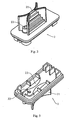
Fig. 1 is a perspective view showing the ink cartridge for inkjet printer of an embodiment of the present invention; -
Fig. 2 is a perspective view showing the cover of the ink cartridge for inkjet printer of an embodiment of the present invention; -
Fig. 3 is another perspective view showing the cover of the ink cartridge for inkjet printer of an embodiment of the present invention; -
Fig. 4 is a perspective view showing the main body of the ink cartridge for inkjet printer of an embodiment of the present invention; -
Fig. 5 is another perspective view showing the main body of the ink cartridge for inkjet printer of an embodiment of the present invention; -
Fig. 6 is a top view showing the cover of the ink cartridge for inkjet printer of an embodiment of the present invention; and -
Fig. 7 is a cross-sectional view taken along line C-C ofFig. 6 , showing the ink cartridge for inkjet printer of an embodiment of the present invention. - Hereinafter, the present invention will be further described in detail in combination with the drawings and the depicted embodiments.
-
Figs. 1-7 show an embodiment of the ink cartridge for inkjet printer according the present invention. When referring to the description drawings of the present invention, directions are based on a state in which an ink cartridge 1 has been mounted on a printer, namely based on the disposition state of the ink cartridge shown inFig. 7 . - The ink cartridge 1 comprises a
main body 3 and acover 2. - The
main body 3 is provided with aliquid storing chamber 30 for storing ink, anair introducing post 34 used for communicating theliquid storing chamber 30 with the outside atmosphere, anink supply port 32 going through the bottom wall of themain body 3 for supplying ink to a printer, a balancingchamber 313 for regulating the pressure in the liquid chamber, a detectingchamber 315 for monitoring the ink storing amount in the liquid storing chamber, and afloater 316 in the detectingchamber 315. The lower portion of theink supply port 32 is designed as acylindrical chamber 321. A sealingmember 322 mated with the ink supply needle of a printer is disposed in the vicinity of the lower end surface of thecylindrical chamber 321. Generally, aheat sealing membrane 323 is used to seal the lower end surface of thecylindrical chamber 321 after ink has been filled (Fig. 5 andFig. 7 ). - Referring to
Fig. 4, Fig. 5 andFig. 7 , the balancingchamber 313 and the detectingchamber 315 are disposed on the lower portion of aplatform 31 which is near the side wall of themain body 3. The balancingchamber 313 communicates with the detectingchamber 315 via a throughhole 314, and communicates with theliquid storing chamber 30 via a through hole 311 at its bottom in the vertical direction. The throughhole 314 is located near the top portion of both thebalancing chamber 313 and the detectingchamber 315. The detectingchamber 315 and theliquid storing chamber 30 are in communication with each other via aliquid guiding port 317 whose position is lower than the bottom of the balancingchamber 313, and whose lowest end and the bottom of theliquid storing chamber 30 are substantially on the same level. Afloater 316 is located in the detectingchamber 315. In order to ensure thefloater 316 can float on the ink liquid surface, the density of thefloater 316 should be lower than that of the ink in theliquid storing chamber 30, and the contact area between thefloater 316 and the liquid surface should be an appropriate value. Generally, for convenience in installation, an opening is first formed at the bottom 312 of the detectingchamber 315, and then thefloater 316 is put into the detectingchamber 315, and last the opening is hermetically closed by amembrane 3110. The wall of themain body 3 where the detectingchamber 315 is disposed is made of transparent or light transparent material for convenient monitoring. Accordingly, the condition of the ink liquid in the ink cartridge may be conveniently monitored by naked eyes or by using an optical sensor. The ink cartridge is designed so that the ink in theliquid storing chamber 30 is consumed first. Thefloater 316 stays near the top of detectingchamber 315 until the ink in theliquid storing chamber 30 is consumed to the upper end of the through hole 311 or to the upper end of theliquid guiding port 317, namely, until air enters the balancingchamber 313. Therefore, the ink contained in theliquid storing chamber 30 is furthest used to reduce the amount of residual ink. - The bottom of the
air introducing post 34 is lower in position than the bottom of theliquid storing chamber 30. The upper end of theair introducing post 34 is higher than the liquid surface of the ink stored in theliquid storing chamber 30, and is in air communication with theliquid storing chamber 30. Anair guiding chamber 341 is provided on the bottom of theair introducing post 34. The air guiding chamber consists of a part of theside walls 342 of themain body 3 and is located lower in position than the bottom ofliquid storing chamber 30. The lower portion of theair guiding chamber 341 is open and communicates withair introducing post 34. The upper portion of theair guiding chamber 341 communicates with the outside atmosphere via anair opening 343, anair groove 332 formed in the bottom wall of themain body 3, and anopening 331 on the bottom wall of themain body 3 in turn. After thewaterproof sponge 3410 is plugged into theair guiding chamber 341, the bottom opening of theair guiding chamber 341 is closed by a heat sealing membrane. Before the ink cartridge is put onto a printer for use, theopening 331 is closed by a sealing member which is made of the same material as theheat sealing membrane 323 and which is formed integrally with theheat sealing membrane 323. A thickened protrudingplatform 33 is formed on the bottom wall of themain body 3 on which theair opening 343, theair groove 332, and theopening 331 are provided by means of partial thickening of the bottom wall to enhance the strength of the relevant portion. When thewaterproof sponge 3410 together with thelabyrinthic air groove 332 are implemented, it is hard for the ink in the ink cartridge to enter theair guiding chamber 341 and the relevant portion of theair groove 332. Accordingly, it is ensured that there is no ink leaking out from the ink cartridge when the heat sealing membrane is peeled off before the ink cartridge is mounted onto a printer. - Referring to
Fig. 2, Fig. 3 andFig. 7 , thecover 2 is used for covering themain body 3. A protrudingportion 21 and aliquid filling port 22 for filling ink are provided on thecover 2. In a state in which themain body 3 and thecover 2 have been assembled together, the protrudingportion 21 is located on the outer side of the top of themain body 3. The part of thecover 2 corresponding to the position of the protrudingportion 21 concaves to the protrudingportion 21 and forms arecess 23 which is helpful to regulate the pressure state in the ink cartridge. - Before being put onto an inkjet printer for use, the ink cartridge for inkjet printer of the present invention is first filled with ink from the
liquid filling port 22 in a negative pressure environment, and then theliquid filling port 22 is sealed by a plastic plug in the negative pressure state, so the inner chamber of the ink cartridge maintains the negative pressure state. - In order to ensure that the detecting
chamber 315 is completely full of ink and has no air, the ink cartridge for inkjet printer of the present invention should stand slantwise on its side for seconds before it is mounted onto a printer for use. As a result, thefloater 316 is in the top of the detectingchamber 315 in the vertical direction to sufficiently perform its indication function. That the ink cartridge stands slantwise on its side means the state in which the bottom of the detectingchamber 315 is in the lower position and the top of the detectingchamber 315 is in the upper position with respect to the vertical direction. When the ink cartridge restores the normal disposition state in which the ink cartridge is working, thefloater 316 rises and floats to the top of the detectingchamber 315 in the vertical direction. When the ink cartridge is in the normal operating state, the top of the detectingchamber 315 in the vertical direction is set as the region for observation by eyes or for detection by an optical sensor, to monitor the amount of ink in the ink cartridge. - The ink cartridge for inkjet printer of the present invention includes three chambers having respective functions: the liquid storing chamber, the balancing chamber, and the detecting chamber. A floater for indicating the amount of stored ink is disposed in the detecting chamber. On the ink supply balance side, a waterproof sponge having multiple apertures and having a strong buffer and regulating function is implemented. Because of the pressure regulating function of the balancing chamber, and the buffer and regulating function of the waterproof sponge, the floater can sink or float as the ink storing amount in the liquid storing chamber changes. Further, changes in the amount of ink stored in the liquid storing chamber can be monitored by naked eyes, or by an optical sensor, so the amount of the residual ink is reduced.
Claims (6)
- An ink cartridge for inkjet printer comprising:a main body (3) and a cover (2) used for covering said main body (3);a liquid storing chamber (30) for storing ink and an air introducing post (34) communicating said liquid storing chamber (30) with the outside atmosphere;wherein further a balancing chamber (313), a detecting chamber (315) and a floater (316) are disposed in the main body (3), the balancing chamber (313) and the detecting chamber (315) are communicated via a through hole (314);said balancing chamber (313) communicates with said liquid storing chamber (30) at its bottom in the vertical direction, said detecting chamber (315) and said liquid storing chamber (30) communicate with each other via a liquid guiding hole (317);said floater (316) which density is lower than that of the ink in said liquid storing chamber (30) is located in said detecting chamber (315).
- The ink cartridge for inkjet printer according to claim 1, wherein:a liquid filling port (22) for filling ink is disposed on said cover (2); andthe lower portion of said air introducing post (34) in the vertical direction communicates with the outside atmosphere via a waterproof sponge (3410).
- The ink cartridge for inkjet printer according to claim 2, wherein:said through hole (314) is located on the upper portion of both said balancing chamber (313) and said detecting chamber (315) in the vertical direction.
- The ink cartridge for inkjet printer according to any one of claim 1 to claim 3, wherein:the position of said liquid guiding port (317) is lower than the bottom of said balancing chamber (313) in the vertical direction.
- The ink cartridge for inkjet printer according to claim 4, wherein:said waterproof sponge (3410) is plugged in an air guiding chamber (341) which position is lower than the bottom of said liquid storing chamber (30) in the vertical direction, and which upper portion in the vertical direction communicates with the atmosphere outside via an air groove (332) going through the bottom wall of said main body (3).
- The ink cartridge for inkjet printer according to claim 5, wherein:said cover (2) is provided with a protruding portion (21), in a state in which said main body (3) and said cover (2) have been assembled together, said protruding portion (21) is out of the top of said main body (3) in the vertical direction, the part of said cover (2) corresponding to the position of said protruding portion (21) concaves to said protruding portion (21) and forms a recess (23).
Applications Claiming Priority (2)
| Application Number | Priority Date | Filing Date | Title |
|---|---|---|---|
| CNU2005200620706U CN2803708Y (en) | 2005-07-25 | 2005-07-25 | Ink cartridge of ink jetting printer |
| PCT/CN2006/001645 WO2007012255A1 (en) | 2005-07-25 | 2006-07-11 | An ink cartridge for inkjet printer |
Publications (4)
| Publication Number | Publication Date |
|---|---|
| EP1908594A1 EP1908594A1 (en) | 2008-04-09 |
| EP1908594A4 EP1908594A4 (en) | 2010-03-17 |
| EP1908594B1 true EP1908594B1 (en) | 2011-04-06 |
| EP1908594B8 EP1908594B8 (en) | 2011-09-21 |
Family
ID=36909007
Family Applications (1)
| Application Number | Title | Priority Date | Filing Date |
|---|---|---|---|
| EP06761400A Ceased EP1908594B8 (en) | 2005-07-25 | 2006-07-11 | An ink cartridge for inkjet printer |
Country Status (4)
| Country | Link |
|---|---|
| US (1) | US8128209B2 (en) |
| EP (1) | EP1908594B8 (en) |
| CN (1) | CN2803708Y (en) |
| WO (1) | WO2007012255A1 (en) |
Families Citing this family (9)
| Publication number | Priority date | Publication date | Assignee | Title |
|---|---|---|---|---|
| CN2905437Y (en) * | 2006-04-15 | 2007-05-30 | 珠海天威技术开发有限公司 | Print cartridge |
| JP4563502B2 (en) * | 2007-01-09 | 2010-10-13 | ロンホァ ソン | Floating display device |
| CN101249753B (en) * | 2007-02-24 | 2011-06-08 | 珠海天威飞马打印耗材有限公司 | Ventilating method for cartridge of ink-jet printer |
| CN101462410B (en) * | 2008-12-31 | 2011-11-02 | 珠海纳思达电子科技有限公司 | Ink cartridge for ink jet printer |
| DE102010027133A1 (en) * | 2009-07-15 | 2011-02-03 | Brendel, Hubert, Dr.-Ing. | Sponge-less ink cartridge for ink jet printer, has light barrier whose light blocking part changes distance of auxiliary ink chamber to sensitive area of light barrier according to change of ink mirror in auxiliary ink chamber |
| RU2533107C2 (en) | 2010-07-15 | 2014-11-20 | Сейко Эпсон Корпорейшн | Container for liquid and liquid ejection system |
| US20120133713A1 (en) * | 2010-11-29 | 2012-05-31 | Camp Alphonse D | Ink tank with flexible wall |
| JP6436351B2 (en) * | 2015-03-27 | 2018-12-12 | ブラザー工業株式会社 | TANK UNIT FOR INKJET RECORDING DEVICE, INKJET RECORDING DEVICE AND VOLATILE ORGANIC COMPOUND ADSORPTION METHOD |
| CN106827820B (en) * | 2017-02-28 | 2018-08-03 | 中山市锦昱辰打印耗材有限公司 | Printer Cartridges |
Family Cites Families (12)
| Publication number | Priority date | Publication date | Assignee | Title |
|---|---|---|---|---|
| JPH09220817A (en) | 1996-02-19 | 1997-08-26 | Sony Corp | Inkjet recording device and ink cartridge |
| JPH10119297A (en) * | 1996-10-17 | 1998-05-12 | Brother Ind Ltd | Ink remaining amount detector |
| CN1188284A (en) | 1997-11-21 | 1998-07-22 | 唐康 | Telephone bank safety operating system |
| CN1188284C (en) * | 2001-12-11 | 2005-02-09 | 珠海天威飞马打印耗材有限公司 | Ink-cases of printers |
| US6254227B1 (en) | 2000-07-14 | 2001-07-03 | Xerox Corporation | Ink cartridge with spillover dam |
| KR100354769B1 (en) * | 2000-11-06 | 2002-10-05 | 삼성전자 주식회사 | Ink cartridge for ink jet printer |
| KR100433529B1 (en) * | 2001-12-04 | 2004-05-31 | 삼성전자주식회사 | Ink cartridge with pressure-controlling module |
| CN2544940Y (en) | 2002-04-27 | 2003-04-16 | 珠海纳思达电子科技有限公司 | Ink cartridge of printer |
| EP1366908A1 (en) * | 2002-05-23 | 2003-12-03 | Agfa-Gevaert N.V. | Ink tank for feeding a shuttling inkjet printing head |
| TWI246465B (en) | 2003-09-30 | 2006-01-01 | Brother Ind Ltd | Ink cartridge and ink-jet printer |
| CN2691854Y (en) | 2004-02-06 | 2005-04-13 | 珠海天威飞马打印耗材有限公司 | Constant pressure continuous ink supplying device |
| CN2759782Y (en) | 2005-01-18 | 2006-02-22 | 珠海天威飞马打印耗材有限公司 | Ink cartridge for ink-jet printer |
-
2005
- 2005-07-25 CN CNU2005200620706U patent/CN2803708Y/en not_active Expired - Lifetime
-
2006
- 2006-07-11 EP EP06761400A patent/EP1908594B8/en not_active Ceased
- 2006-07-11 US US11/989,394 patent/US8128209B2/en not_active Expired - Fee Related
- 2006-07-11 WO PCT/CN2006/001645 patent/WO2007012255A1/en not_active Ceased
Also Published As
| Publication number | Publication date |
|---|---|
| CN2803708Y (en) | 2006-08-09 |
| US20100149292A1 (en) | 2010-06-17 |
| EP1908594B8 (en) | 2011-09-21 |
| WO2007012255A1 (en) | 2007-02-01 |
| EP1908594A4 (en) | 2010-03-17 |
| EP1908594A1 (en) | 2008-04-09 |
| US8128209B2 (en) | 2012-03-06 |
Similar Documents
| Publication | Publication Date | Title |
|---|---|---|
| EP1010536B1 (en) | Ink cartridge for ink jet printer | |
| US6929357B2 (en) | Ink cartridge having bellows valve, ink filling method and apparatus used thereof | |
| US6238042B1 (en) | Ink cartridge for ink jet printer and method of charging ink into said cartridge | |
| US6905198B2 (en) | Liquid supply vessel | |
| US7475972B2 (en) | One-way valve, valve unit assembly, and ink cartridge using the same | |
| KR100880048B1 (en) | Ink cartridge, ink filling method and filling device | |
| JP2005161853A (en) | Fluid container system for housing fluid therein, and method of ventilating interior of fluid container | |
| EP1908594B1 (en) | An ink cartridge for inkjet printer | |
| JP2008195081A (en) | Ink cartridge for inkjet recording device | |
| EP0703083B1 (en) | Ink cartridge for ink jet printer | |
| JP5109536B2 (en) | Ink container manufacturing method | |
| JP5157327B2 (en) | Ink container and container for ink container | |
| US20060232649A1 (en) | Ink cartridge for inkjet printer | |
| CN2759782Y (en) | Ink cartridge for ink-jet printer | |
| US20050243147A1 (en) | Ink cartridge having bellows valve, ink filling method and apparatus used thereof | |
| CA2552635C (en) | Ink cartridge for an inkjet printer | |
| WO2007118415A1 (en) | An ink cartridge | |
| RU2259923C2 (en) | Ink cartridge, method and device for ink priming | |
| CN204398534U (en) | A kind of print cartridge for ink-jet printer | |
| CN201064975Y (en) | Ink-jet ink box | |
| CN111300991B (en) | Ink transfer bin and ink supply mechanism of inkjet printer | |
| JPH0436058Y2 (en) | ||
| HK1028971B (en) | Ink cartridge for ink jet printer | |
| JP2002317800A (en) | Manual fluid supplying device | |
| HK1028972B (en) | Ink cartridge for ink jet printer |
Legal Events
| Date | Code | Title | Description |
|---|---|---|---|
| PUAI | Public reference made under article 153(3) epc to a published international application that has entered the european phase |
Free format text: ORIGINAL CODE: 0009012 |
|
| 17P | Request for examination filed |
Effective date: 20080130 |
|
| AK | Designated contracting states |
Kind code of ref document: A1 Designated state(s): FR |
|
| RBV | Designated contracting states (corrected) |
Designated state(s): FR |
|
| A4 | Supplementary search report drawn up and despatched |
Effective date: 20100211 |
|
| GRAP | Despatch of communication of intention to grant a patent |
Free format text: ORIGINAL CODE: EPIDOSNIGR1 |
|
| GRAS | Grant fee paid |
Free format text: ORIGINAL CODE: EPIDOSNIGR3 |
|
| GRAA | (expected) grant |
Free format text: ORIGINAL CODE: 0009210 |
|
| AK | Designated contracting states |
Kind code of ref document: B1 Designated state(s): FR |
|
| RAP2 | Party data changed (patent owner data changed or rights of a patent transferred) |
Owner name: PRINT-RITE. UNICORN IMAGE PRODUCTS CO., LTD. OF ZH |
|
| PLBE | No opposition filed within time limit |
Free format text: ORIGINAL CODE: 0009261 |
|
| STAA | Information on the status of an ep patent application or granted ep patent |
Free format text: STATUS: NO OPPOSITION FILED WITHIN TIME LIMIT |
|
| 26N | No opposition filed |
Effective date: 20120110 |
|
| REG | Reference to a national code |
Ref country code: FR Ref legal event code: PLFP Year of fee payment: 11 |
|
| REG | Reference to a national code |
Ref country code: FR Ref legal event code: PLFP Year of fee payment: 12 |
|
| REG | Reference to a national code |
Ref country code: FR Ref legal event code: PLFP Year of fee payment: 13 |
|
| PGFP | Annual fee paid to national office [announced via postgrant information from national office to epo] |
Ref country code: FR Payment date: 20210713 Year of fee payment: 16 |
|
| PG25 | Lapsed in a contracting state [announced via postgrant information from national office to epo] |
Ref country code: FR Free format text: LAPSE BECAUSE OF NON-PAYMENT OF DUE FEES Effective date: 20220731 |