EP1908552A2 - Apparatus for generating a high-pressure fluid jet - Google Patents
Apparatus for generating a high-pressure fluid jet Download PDFInfo
- Publication number
- EP1908552A2 EP1908552A2 EP20080000704 EP08000704A EP1908552A2 EP 1908552 A2 EP1908552 A2 EP 1908552A2 EP 20080000704 EP20080000704 EP 20080000704 EP 08000704 A EP08000704 A EP 08000704A EP 1908552 A2 EP1908552 A2 EP 1908552A2
- Authority
- EP
- European Patent Office
- Prior art keywords
- mixing tube
- cutting head
- collar
- bore
- pressure fluid
- Prior art date
- Legal status (The legal status is an assumption and is not a legal conclusion. Google has not performed a legal analysis and makes no representation as to the accuracy of the status listed.)
- Withdrawn
Links
- 239000012530 fluid Substances 0.000 title claims abstract description 37
- 238000011144 upstream manufacturing Methods 0.000 abstract description 11
- 239000010437 gem Substances 0.000 abstract description 7
- 229910001751 gemstone Inorganic materials 0.000 abstract description 7
- 239000000463 material Substances 0.000 description 10
- XLYOFNOQVPJJNP-UHFFFAOYSA-N water Substances O XLYOFNOQVPJJNP-UHFFFAOYSA-N 0.000 description 7
- 239000003082 abrasive agent Substances 0.000 description 3
- 229920002635 polyurethane Polymers 0.000 description 3
- 239000004814 polyurethane Substances 0.000 description 3
- 238000004519 manufacturing process Methods 0.000 description 2
- 238000000034 method Methods 0.000 description 2
- 239000007921 spray Substances 0.000 description 2
- WUBBRNOQWQTFEX-UHFFFAOYSA-N 4-aminosalicylic acid Chemical compound NC1=CC=C(C(O)=O)C(O)=C1 WUBBRNOQWQTFEX-UHFFFAOYSA-N 0.000 description 1
- 239000000853 adhesive Substances 0.000 description 1
- 230000001070 adhesive effect Effects 0.000 description 1
- 230000009286 beneficial effect Effects 0.000 description 1
- 239000002184 metal Substances 0.000 description 1
- 239000002245 particle Substances 0.000 description 1
- 239000004033 plastic Substances 0.000 description 1
- 229920003023 plastic Polymers 0.000 description 1
- 229910001220 stainless steel Inorganic materials 0.000 description 1
- 239000010935 stainless steel Substances 0.000 description 1
Images


Classifications
-
- B—PERFORMING OPERATIONS; TRANSPORTING
- B24—GRINDING; POLISHING
- B24C—ABRASIVE OR RELATED BLASTING WITH PARTICULATE MATERIAL
- B24C5/00—Devices or accessories for generating abrasive blasts
- B24C5/02—Blast guns, e.g. for generating high velocity abrasive fluid jets for cutting materials
- B24C5/04—Nozzles therefor
-
- B—PERFORMING OPERATIONS; TRANSPORTING
- B24—GRINDING; POLISHING
- B24C—ABRASIVE OR RELATED BLASTING WITH PARTICULATE MATERIAL
- B24C1/00—Methods for use of abrasive blasting for producing particular effects; Use of auxiliary equipment in connection with such methods
- B24C1/04—Methods for use of abrasive blasting for producing particular effects; Use of auxiliary equipment in connection with such methods for treating only selected parts of a surface, e.g. for carving stone or glass
- B24C1/045—Methods for use of abrasive blasting for producing particular effects; Use of auxiliary equipment in connection with such methods for treating only selected parts of a surface, e.g. for carving stone or glass for cutting
-
- B—PERFORMING OPERATIONS; TRANSPORTING
- B26—HAND CUTTING TOOLS; CUTTING; SEVERING
- B26F—PERFORATING; PUNCHING; CUTTING-OUT; STAMPING-OUT; SEVERING BY MEANS OTHER THAN CUTTING
- B26F3/00—Severing by means other than cutting; Apparatus therefor
- B26F3/004—Severing by means other than cutting; Apparatus therefor by means of a fluid jet
-
- Y—GENERAL TAGGING OF NEW TECHNOLOGICAL DEVELOPMENTS; GENERAL TAGGING OF CROSS-SECTIONAL TECHNOLOGIES SPANNING OVER SEVERAL SECTIONS OF THE IPC; TECHNICAL SUBJECTS COVERED BY FORMER USPC CROSS-REFERENCE ART COLLECTIONS [XRACs] AND DIGESTS
- Y10—TECHNICAL SUBJECTS COVERED BY FORMER USPC
- Y10T—TECHNICAL SUBJECTS COVERED BY FORMER US CLASSIFICATION
- Y10T83/00—Cutting
- Y10T83/364—By fluid blast and/or suction
Definitions
- the present invention relates to an apparatus for generating a high pressure fluid jet, including an apparatus for generating a high-pressure abrasive water jet.
- High-pressure fluid jets including high-pressure abrasive water jets, are used to cut a wide variety of materials in many different industries.
- Systems for generating high-pressure fluid jets are currently available, for example the Paser 3 system manufactured by Flow International Corporation, the assignee of the present invention.
- a system of this type is shown and described in Flow's U. S. Patent No. 5,643, 058 .
- high pressure fluid typically water
- abrasive particles are fed to a mixing chamber and entrained by the jet as the jet flows through the mixing chamber and a mixing tube.
- the high pressure abrasive water jet is discharged from the mixing tube and directed toward a work piece to cut the workpiece along a selected path.
- Conventional three-axis machines mount the cutting head assembly on a ram that imparts vertical motion along a Z-axis, namely toward and away from the workpiece.
- the ram in turn, is mounted to a bridge via a carriage, the carriage being free to move parallel to a longitudinal axis of the bridge in a horizontal plane.
- the bridge is slideably mounted on one or more rails to move in a direction perpendicular to the longitudinal axis of the bridge. In this manner, the high-pressure fluid jet generated by the cutting head assembly is moved along a desired path in an X-Y plane, and is raised and lowered relative to the workpiece, as may be desired.
- Conventional five-axis machines work in a similar manner but provide for movement about two additional rotary axes, typically about one horizontal axis and one vertical axis.
- the present invention provides such a system.
- an improved system for generating a high-pressure fluid jet for example a high-pressure abrasive water jet.
- the improved apparatus includes a cutting head assembly that carries both an orifice in an orifice mount for generating a high- pressure fluid jet, and a mixing tube positioned within the body of the cutting head downstream of the orifice.
- the cutting head is coupled to a source of high-pressure fluid through a nozzle body, and may also be coupled to a source of abrasive, to generate a high-pressure or high-speed abrasive fluid jet, as is known in the art.
- the orifice mount has a frusto- conical outer surface that seats against a corresponding frusto-conical wall formed in a bore of the cutting head.
- applicants have improved the performance of the orifice mount by reducing the length of the frusto-conical surface, such that a radial distance between the midpoint of the frusto-conical surface and the longitudinal axis or centerline of the orifice mount is reduced, as compared to previously available mounts.
- the length of the corresponding frusto-conical bearing surface in the cutting head is also reduced, as compared to conventional systems, and in a preferred embodiment, is less than the length of the frusto-conical surface of the orifice mount.
- a collar is rigidly fixed to an outer surface of the mixing tube in an upper region of the mixing tube.
- the bore of the cutting head forms a shoulder downstream of a mixing chamber in the cutting head, and flares outward, from a point downstream of the shoulder to the distal end of the cutting head.
- the collar on the mixing tube is sized to slide upward through the bore of the cutting head and seat against the shoulder of the cutting head. Because the collar is rigidly fixed to the outer surface of the mixing tube, it locates the mixing tube in a selected, specific longitudinal position, when the collar registers against the shoulder, thereby preventing the mixing tube from being inserted any farther into the cutting head.
- the collar may be cylindrical, and supported by a collet that is positioned around the mixing tube and inserted into the flared end of the cutting head bore.
- the collar may be substantially frusto-conical, such that it both seats against the shoulder and mates with the conical surface of the bore, thereby locating the mixing tube both longitudinally and radially.
- the mixing tube may be located precisely within the cutting head, wholly eliminating the need for a pin, insert, or other device known in the art to register the mixing tube. In this manner, manufacturing is more simple and cost effective, and the volume of the mixing chamber is not impinged upon by a pin or insert, etc.
- the collar may be rigidly fixed to an outer surface of the mixing tube at any desired point along the length of the mixing tube, allowing the inlet of the mixing tube to be positioned selectively and accurately.
- operation of the system may be tuned to optimize performance for changes in known operating parameters, such as abrasive size, abrasive type, orifice size and location, fluid pressure, and flow rate.
- High-pressure fluid is provided to the system via a nozzle body coupled to the cutting head.
- the bore of the cutting head is provided with pilot surfaces both upstream and downstream of threads in the cutting head bore.
- an outer surface of the nozzle body is provided with corresponding threads and pilot surfaces upstream and downstream of the nozzle body threads.
- the pilot surfaces of the cutting head engage the corresponding pilot surfaces of the nozzle body when the threads of the nozzle body and cutting head are engaged.
- a shield is coupled to an end region of the cutting head assembly, surrounding an end region of the mixing tube, to contain the spray of the jet.
- a disk of wear-resistant material such as polyurethane, is positioned in an inner region of the shield.
- an improved high-pressure abrasive water jet assembly 10 is provided in accordance with a preferred embodiment of the present invention.
- the assembly 10 includes a cutting head 22 that contains a jewel orifice 20 held by an orifice mount 11, and mixing tube 49.
- high-pressure fluid is provided to the orifice 20 through nozzle body 37 to generate a high-pressure fluid jet, into which abrasives may be entrained via port 74.
- the cutting head is provided with a second port to allow the introduction of a second fluid, for example air, or to allow the cutting head to be connected to a vacuum source or sensors.
- the high-pressure fluid jet and entrained abrasives flow through mixing tube 49 and exit the mixing tube as an abrasive water jet.
- the orifice mount 11 has a frusto-conical outer surface 12 that seats against a corresponding frusto-conical wall 26 formed in a bore 23 of cutting head 22.
- distance 16 between the midpoint 15 of the frusto-conical surface 12 and a top surface 17 of the orifice mount 11 is also maximized, thereby increasing the stability of the orifice mount under pressure.
- length 69 is 2,5 - 5,1 mm (0.1 - 0. 2 inch).
- distance 13 is 2,79 - 4,83 mm (0.11 - 0.19 inch), and preferably 3,81 - 4,7 mm (0.15 - 0.185 inch).
- distance 16 is 3,81 - 7,6 mm (0.15 - 0. 3 inch).
- this preferred geometry for the orifice mount 11 is appropriate whether the jewel orifice 20 is recessed below the top surface 17 of mount 11, or is substantially flush with the top surface of the orifice mount. While the geometry provides improved stability and reduced deformation regardless of the type, location and method of securing the jewel orifice, applicants believe the increased stability achieved in accordance with the present invention is particularly beneficial when the jewel orifice 20 is mounted with a hard seal, for example, with a metallic seal.
- the orifice mount 11 is provided with an annular member 19 extending parallel to the longitudinal axis 14 of the orifice mount, below the frusto-conical surface 12.
- the annular member 19 When assembled into a cutting head, the annular member 19 may be aligned with a vent 35, as shown in Figure 4A , that is open to atmosphere.
- vent 35 extends laterally from an outer surface 36 of the cutting head 22 to the bore of the cutting head, to a point adjacent the annular member of the orifice mount, downstream of the frusto-conical wall 26 of the cutting head.
- the provision of a vent 35 relieves a vacuum that typically forms below the orifice mount during operation of the high-pressure fluid jet system. A vacuum in this area causes reverse flow of abrasives and results in mixing inefficiency. This problem is reduced in accordance with the present invention.
- the orifice mount 11 is made from a material having a 2% yield strength of above 6,9 * 10 2 MPa (100,000 psi).
- materials include stainless steel PH 15-5, PH 17-4, and 410/416.
- the cutting head 22 is provided with a bore 23 extending therethrough along a longitudinal axis 24.
- a first region 25 of the bore 23 forms a frusto-conical wall 26 in the cutting head body.
- a radial distance 27 between the longitudinal axis 24 of the cutting head and a midpoint 28 of the frusto-conical wall 26 is reduced as compared to conventional cutting heads.
- distance 27 is 2,79 - 4,83 mm (0.11 - 0.19 inch), and preferably 5,1 - 11,9 mm (0.15 - 0.185 inch).
- the midpoint 28 of the frustoconical wall 26 approximately aligns with the midpoint 15 of frusto-conical surface 12 within a distance of 1,27 mm (0.05 inch).
- a ratio of length 68 to diameter 70 is 5,1 - 11,9 mm (0.2 - 0. 47 inch).
- a ratio of the length 69 of the frusto-conical surface 12 to diameter 70 is 5,1 - 11,9 mm (0.2 - 0.47 inch).
- nozzle body 37 has a bore 38 extending therethrough along longitudinal axis 39.
- a first region 40 of nozzle body 37 is provided with a plurality of threads 41 on an outer surface of the nozzle body.
- the nozzle body 37 is further provided with a first pilot wall 42 upstream of the threads 41 and a second pilot wall 43 downstream of threads 41.
- a region 29 of the bore 23 extending through cutting head 22 is provided with a plurality of threads 30.
- This region of the cutting head bore is also provided with a first pilot wall 31 upstream of threads 30 and with a second pilot wall 32, downstream of the threads 30.
- the bore 23 of cutting head 22 further defines a mixing chamber 33 and a shoulder 34, downstream of mixing chamber 33.
- a mixing tube 49 having a bore 50 extending therethrough along a longitudinal axis 51 to define an inlet 63 and an outlet, is positioned in the cutting head 22.
- the mixing tube 49 is provided with a collar 52 rigidly fixed to an outer surface 53 of the mixing tube, in an upper region 54 of the mixing tube.
- the collar can also be formed during the manufacturing process for making the mixing tube and machined to final dimensions by grinding.
- the collar may be made out of metal, plastic, or the same material as the mixing tube.
- the collar 52 has a sufficiently small outer diameter to slide upward through the bore 23 of the cutting head, yet the outer diameter of the collar is sufficiently large that it seats against shoulder 34 and prevents the mixing tube from being inserted further into the cutting head 22.
- a wall thickness 75 of collar 52 is 0,254 - 0,508 mm (0.01 - 0.2 inch). Because the collar 52 is rigidly fixed to an outer surface of the mixing tube, it precisely locates the mixing tube axially, within the bore of the cutting head 22, without the need for pins, inserts or other structure currently used in the art to locate the mixing tube.
- An o-ring 73 may be positioned between the collar 52 and shoulder 34 to seal the mixing chamber 33 from back flow.
- the collar 52 is cylindrical, and is used to position the mixing tube against the collet 71 and collet nut 72, that is selectively tightened and loosened against the assembly.
- the bore 23 of cutting head 22 is conical downstream of shoulder 34, to matingly engage the outer walls of collet 71.
- the collar that is rigidly fixed to an outer surface of the mixing tube may be frusto-conical, such that when the mixing tube 49 is inserted into the distal end of the cutting head, the collar 58 locates the mixing tube both axially and radially.
- Collar 52 may be rigidly fixed to an outer surface of the mixing tube 49 at any desired location, to precisely position the inlet 63 of the mixing tube at a specific location in the cutting head bore 23. While the exact location of collar 52 may be fine tuned depending on the operating parameters, in a preferred embodiment, a distance 57 between a top surface 55 of the mixing tube and a bottom surface 56 of collar 52 is 0,51 mm - 5,1 cm (0.02 - 2.0 inch). In this manner, the tool tip accuracy of the system is improved.
- the mixing tube 49 is provided with a first cylindrical region 65 adjacent the inlet 63 to the mixing tube, the outer diameter 66 of the first cylindrical region 65 being less than the outer diameter 67 of the mixing tube 49 downstream of the first cylindrical region. In this manner, a step caused by the change in outer diameter of the mixing tube seats against the shoulder 34 in the cutting head 22, accurately locating the mixing tube in a selected axial position.
- a frusto-conical collar 59 is positioned on mixing tube 49, which in turn is held via an interference fit in a nut 60 that has threads 61 to engage a threaded inner surface 62 of a cutting head.
- the improved apparatus for generating a high- pressure fluid jet includes a shield 44 coupled to an end region 46 of the cutting head.
- the shield 44 is provided with a flange 45 that forms an interference fit with a groove in the collet nut 72.
- An annular skirt 47 extends downward from the flange 45 surrounding an end region of the mixing tube 49. In this manner, the shield substantially contains spray from the fluid jet.
- a disk 48 of wear-resistant material, such as polyurethane, is positioned in an inner region of the shield 44.
Landscapes
- Engineering & Computer Science (AREA)
- Mechanical Engineering (AREA)
- Life Sciences & Earth Sciences (AREA)
- Forests & Forestry (AREA)
- Perforating, Stamping-Out Or Severing By Means Other Than Cutting (AREA)
- Jet Pumps And Other Pumps (AREA)
- Surgical Instruments (AREA)
Abstract
Description
- The present invention relates to an apparatus for generating a high pressure fluid jet, including an apparatus for generating a high-pressure abrasive water jet.
- High-pressure fluid jets, including high-pressure abrasive water jets, are used to cut a wide variety of materials in many different industries. Systems for generating high-pressure fluid jets are currently available, for example the Paser 3 system manufactured by Flow International Corporation, the assignee of the present invention. A system of this type is shown and described in Flow's U. S. Patent No.
5,643, 058 . In such systems, high pressure fluid, typically water, flows through an orifice in a cutting head to form a high pressure jet. If desired, abrasive particles are fed to a mixing chamber and entrained by the jet as the jet flows through the mixing chamber and a mixing tube. The high pressure abrasive water jet is discharged from the mixing tube and directed toward a work piece to cut the workpiece along a selected path. - Various systems are currently available to move a high-pressure fluid jet along a selected path. Such systems are commonly referred to as two-axis, three-axis and five-axis machines.
- Conventional three-axis machines mount the cutting head assembly on a ram that imparts vertical motion along a Z-axis, namely toward and away from the workpiece. The ram, in turn, is mounted to a bridge via a carriage, the carriage being free to move parallel to a longitudinal axis of the bridge in a horizontal plane. The bridge is slideably mounted on one or more rails to move in a direction perpendicular to the longitudinal axis of the bridge. In this manner, the high-pressure fluid jet generated by the cutting head assembly is moved along a desired path in an X-Y plane, and is raised and lowered relative to the workpiece, as may be desired. Conventional five-axis machines work in a similar manner but provide for movement about two additional rotary axes, typically about one horizontal axis and one vertical axis.
- Applicants believe it is desirable and possible to provide an improved system for generating a high-speed fluid jet. The present invention provides such a system.
- Briefly, an improved system for generating a high-pressure fluid jet, for example a high-pressure abrasive water jet.
More particularly, the improved apparatus includes a cutting head assembly that carries both an orifice in an orifice mount for generating a high- pressure fluid jet, and a mixing tube positioned within the body of the cutting head downstream of the orifice. The cutting head is coupled to a source of high-pressure fluid through a nozzle body, and may also be coupled to a source of abrasive, to generate a high-pressure or high-speed abrasive fluid jet, as is known in the art.
The orifice mount has a frusto- conical outer surface that seats against a corresponding frusto-conical wall formed in a bore of the cutting head. As described previously in U. S. Patent No.5,643, 058 , it is desirable for the frusto-conical surface of the orifice mount to form an included angle of 55-80°. However, applicants have improved the performance of the orifice mount by reducing the length of the frusto-conical surface, such that a radial distance between the midpoint of the frusto-conical surface and the longitudinal axis or centerline of the orifice mount is reduced, as compared to previously available mounts. The length of
the corresponding frusto-conical bearing surface in the cutting head is also reduced, as compared to conventional systems, and in a preferred embodiment, is less than the length of the frusto-conical surface of the orifice mount. By minimizing the distance between the longitudinal axis of the assembly, which corresponds to the longitudinal axis or centerline of the orifice mount and the cutting head, and the center points of the bearing surfaces of the cutting head and the orifice mount, deflection of the mount under pressure is reduced. A distance between the midpoint of the frusto-conical surface of the orifice mount and a top surface of the orifice mount is also maximized to increase the stability of the orifice mount under pressure. By providing apparatus in accordance with the present invention, the wear characteristics and accuracy of the assembly are improved, thereby reducing cost and improving the overall performance of the system.
A collar is rigidly fixed to an outer surface of the mixing tube in an upper region of the mixing tube. The bore of the cutting head forms a shoulder downstream of a mixing chamber in the cutting head, and flares outward, from a point downstream of the shoulder to the distal end of the cutting head. The collar on the mixing tube is sized to slide upward through the bore of the cutting head and seat against the shoulder of the cutting head. Because the collar is rigidly fixed to the outer surface of the mixing tube, it locates the mixing tube in a selected, specific longitudinal position, when the collar registers against the shoulder, thereby preventing the mixing tube from being inserted any farther into the cutting head.
The collar may be cylindrical, and supported by a collet that is positioned around the mixing tube and inserted into the flared end of the cutting head bore. Alternatively, the collar may be substantially frusto-conical, such that it both seats against the shoulder and mates with the conical surface of the bore, thereby locating the mixing tube both longitudinally and radially. In this manner, the mixing tube may be located precisely within the cutting head, wholly eliminating the need for a pin, insert, or other device known in the art to register the mixing tube. In this manner, manufacturing is more simple and cost effective, and the volume of the mixing chamber is not impinged upon by a pin or insert, etc. Furthermore, it will be understood that the
collar may be rigidly fixed to an outer surface of the mixing tube at any desired point along the length of the mixing tube, allowing the inlet of the mixing tube to be positioned selectively and accurately. In this manner, operation of the system may be tuned to optimize performance for changes in known operating parameters, such as abrasive size, abrasive type, orifice size and location, fluid pressure, and flow rate. - High-pressure fluid is provided to the system via a nozzle body coupled to the cutting head. To improve the accuracy of the assembly of the nozzle body with the cutting head, the bore of the cutting head is provided with pilot surfaces both upstream and downstream of threads in the cutting head bore. Likewise, an outer surface of the nozzle body is provided with corresponding threads and pilot surfaces upstream and downstream of the nozzle body threads. In this manner, the pilot surfaces of the cutting head engage the corresponding pilot surfaces of the nozzle body when the threads of the nozzle body and cutting head are engaged. Applicants believe that this use of two pilot surfaces longitudinally spaced from each other provides improved results over prior art systems that use only one pilot surface.
- A shield is coupled to an end region of the cutting head assembly, surrounding an end region of the mixing tube, to contain the spray of the jet. In a preferred embodiment, a disk of wear-resistant material, such as polyurethane, is positioned in an inner region of the shield.
-
-
Figure 1 is a cross-sectional elevational view of an assembly for forming a high-pressure fluid jet. -
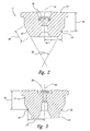
Figure 2 is a cross-sectional elevational view of an orifice mount. -
Figure 3 is an alternative embodiment of an orifice mount. -
Figure 4A is a cross-sectional elevational view of a cutting head. -
Figure 4B is an enlarged detail view of a region of the cutting head shown inFigure 4A . -
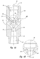
Figure 5 is a cross-sectional elevational view of a nozzle body. -
Figure 6 is a cross-sectional elevational view of a mixing tube assembly. -
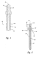
Figure 7 is a partial cross-sectional elevational view of a mixing tube. -
Figure 8 is a partial cross-sectional elevational view of a mixing tube. -
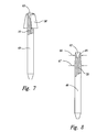
Figure 9A is a partial cross-sectional elevational view of a mixing tube. -
Figure 9B is a partial cross-sectional elevational view of the mixing tube assembly ofFigure 9A shown mounted in a cutting head body. -
Figure 10 is an enlarged elevational view of an orifice mount and a cutting head as shown inFigure 1 . - As illustrated in
Figure 1 , an improved high-pressure abrasivewater jet assembly 10 is provided in accordance with a preferred embodiment of the present invention. Theassembly 10 includes acutting head 22 that contains ajewel orifice 20 held by anorifice mount 11, andmixing tube 49. As is known in the art, high-pressure fluid is provided to theorifice 20 throughnozzle body 37 to generate a high-pressure fluid jet, into which abrasives may be entrained viaport 74. (The cutting head is provided with a second port to allow the introduction of a second fluid, for example air, or to allow the cutting head to be connected to a vacuum source or sensors.) The high-pressure fluid jet and entrained abrasives flow through mixingtube 49 and exit the mixing tube as an abrasive water jet. - In accordance with the present invention, and as best seen in
Figures 2 and3, theorifice mount 11 has a frusto-conicalouter surface 12 that seats against a corresponding frusto-conical wall 26 formed in abore 23 of cuttinghead 22. As discussed above, it is desirable for the frusto-conical surface 12 of theorifice mount 11 to form an includedangle 18 of 55-80°. This angle allows the orifice mount to be easily placed into and removed from the cutting head. - Applicants however, have further improved the performance of the
orifice mount 11, by reducing thelength 69 of the frusto-conical surface 12. As such, aradial distance 13 between amidpoint 15 of the frusto-conical surface 12 and the longitudinal axis orcenterline 14 of theorifice mount 11 is reduced, as compared to conventional mounts. By minimizing thedistance 13 between the longitudinal axis of the orifice mount and thecenter point 15 of the frusto-conical surface 12, deflection of the mount adjacent thejewel orifice 20 when under pressure is reduced. Furthermore, by reducingdistance 13, the mount is more stable when subjected to pressure during operation of the system. To further improve the accuracy of the system,distance 16 between themidpoint 15 of the frusto-conical surface 12 and atop surface 17 of theorifice mount 11 is also maximized, thereby increasing the stability of the orifice mount under pressure. In a preferred embodiment,length 69 is 2,5 - 5,1 mm (0.1 - 0. 2 inch). In a preferred embodiment,distance 13 is 2,79 - 4,83 mm (0.11 - 0.19 inch), and preferably 3,81 - 4,7 mm (0.15 - 0.185 inch). In a preferred embodiment,distance 16 is 3,81 - 7,6 mm (0.15 - 0. 3 inch). - As seen in
Figure 3 , this preferred geometry for theorifice mount 11 is appropriate whether thejewel orifice 20 is recessed below thetop surface 17 ofmount 11, or is substantially flush with the top surface of the orifice mount. While the geometry provides improved stability and reduced deformation regardless of the type, location and method of securing the jewel orifice, applicants believe the increased stability achieved in accordance with the present invention is particularly beneficial when thejewel orifice 20 is mounted with a hard seal, for example, with a metallic seal. - In an alternative embodiment, as shown in
Figure 3 , theorifice mount 11 is provided with anannular member 19 extending parallel to thelongitudinal axis 14 of the orifice mount, below the frusto-conical surface 12. When assembled into a cutting head, theannular member 19 may be aligned with avent 35, as shown inFigure 4A , that is open to atmosphere. In a preferred embodiment, vent 35 extends laterally from anouter surface 36 of the cuttinghead 22 to the bore of the cutting head, to a point
adjacent the annular member of the orifice mount, downstream of the frusto-conical wall 26 of the cutting head. The provision of avent 35 relieves a vacuum that typically forms below the orifice mount during operation of the high-pressure fluid jet system. A vacuum in this area causes reverse flow of abrasives and results in mixing inefficiency.
This problem is reduced in accordance with the present invention. - In a preferred embodiment, the
orifice mount 11 is made from a material having a 2% yield strength of above 6,9 * 102 MPa (100,000 psi). Examples of preferred materials include stainless steel PH 15-5, PH 17-4, and 410/416. - As best seen in
Figures 4A, 4B , and10 , the cuttinghead 22 is provided with abore 23 extending therethrough along alongitudinal axis 24. Afirst region 25 of thebore 23 forms a frusto-conical wall 26 in the cutting head body. Similar to the structure of theorifice mount 11, aradial distance 27 between thelongitudinal axis 24 of the cutting head and amidpoint 28 of the frusto-conical wall 26 is reduced as compared to conventional cutting heads. In a preferred embodiment,distance 27 is 2,79 - 4,83 mm (0.11 - 0.19 inch), and preferably 5,1 - 11,9 mm (0.15 - 0.185 inch). It will be appreciated from the drawings that when theorifice mount 11 is positioned in the cuttinghead 22, the longitudinal axes of the orifice mount and the cutting head are aligned. Also, in a preferred embodiment, themidpoint 28 of thefrustoconical wall 26 approximately aligns with themidpoint 15 of frusto-conical surface 12 within a distance of 1,27 mm (0.05 inch). Given that thelength 68 of the frusto-conical wall 26 must be sufficient to support the load created by the pressure acting on adiameter 70 of abore 38 ofnozzle body 37, a ratio oflength 68 todiameter 70 is 5,1 - 11,9 mm (0.2 - 0. 47 inch). Similarly, in a preferred embodiment, a ratio of thelength 69 of the frusto-conical surface 12 todiameter 70 is 5,1 - 11,9 mm (0.2 - 0.47 inch). - As discussed previously, high-pressure fluid is provided to the cutting head via
nozzle body 37. As best seen inFigures 1 and5 ,nozzle body 37 has abore 38 extending therethrough alonglongitudinal axis 39. Afirst region 40 ofnozzle body 37 is provided with a plurality ofthreads 41 on an outer surface of the nozzle body. Thenozzle body 37 is further provided with afirst pilot wall 42 upstream of thethreads 41 and asecond pilot wall 43 downstream ofthreads 41. As best seen inFigure 4A , aregion 29 of thebore 23 extending through cuttinghead 22 is provided with a plurality ofthreads 30. This region of the cutting head bore is also provided with a first pilot
wall 31 upstream ofthreads 30 and with asecond pilot wall 32, downstream of thethreads 30. When thenozzle body 37 is screwed into cuttinghead 22, the first and second pilot walls of the cutting head engage the first and second pilot walls of the nozzle body, respectively, thereby increasing the accuracy of the alignment of the nozzle body and cutting head. Applicants believe that providing two pilot diameters, longitudinally spaced from one another, provides improved results over conventional systems that use only a single pilot surface. - As further illustrated in
Figure 4A , thebore 23 of cuttinghead 22 further defines a mixingchamber 33 and ashoulder 34, downstream of mixingchamber 33. A mixingtube 49, having abore 50 extending therethrough along alongitudinal axis 51 to define aninlet 63 and an outlet, is positioned in the cuttinghead 22. As illustrated inFigure 6 , the mixingtube 49 is provided with acollar 52 rigidly fixed to anouter surface 53 of the mixing tube, in anupper region 54 of the mixing tube. To rigidly affix the collar to the mixing tube, a variety of methods may be used, including press fitting, shrink fitting, or a suitable adhesive material. The collar can also be formed during the manufacturing process for making the mixing tube and machined to final dimensions by grinding. The collar may be made out of metal, plastic, or the same material as the mixing tube. - The
collar 52 has a sufficiently small outer diameter to slide upward through thebore 23 of the cutting head, yet the outer diameter of the collar is sufficiently large that it seats againstshoulder 34 and prevents the mixing tube from being inserted further into the cuttinghead 22. In a preferred embodiment, as shown inFigure 6 , awall thickness 75 ofcollar 52 is 0,254 - 0,508 mm (0.01 - 0.2 inch). Because thecollar 52 is rigidly fixed to an outer surface of the mixing tube, it precisely locates the mixing tube axially, within the bore of the cuttinghead 22, without the need for pins, inserts or other structure currently used in the art to locate the mixing tube. An o-ring 73 may be positioned between thecollar 52 andshoulder 34 to seal the mixingchamber 33 from back flow. - In a preferred embodiment, the
collar 52 is cylindrical, and is used to position the mixing tube against thecollet 71 andcollet nut 72, that is selectively tightened and loosened against the assembly. As best seen inFigures 1 and4A , thebore 23 of cuttinghead 22 is conical downstream ofshoulder 34, to matingly engage the outer walls ofcollet 71. When thecollet nut 72 is loosened, thecollar 52 rests on the upper surface of thecollet 71, preventing the mixingtube 49 from falling out of the cuttinghead 22, and from being pulled out of the cutting head. Alternatively, as shown inFigure 7 , the collar that is rigidly fixed to an outer surface of the mixing tube may be frusto-conical, such that when the mixingtube 49 is inserted into the distal end of the cutting head, thecollar 58 locates the mixing tube both axially and radially. -
Collar 52 may be rigidly fixed to an outer surface of the mixingtube 49 at any desired location, to precisely position theinlet 63 of the mixing tube at a specific location in the cutting head bore 23. While the exact location ofcollar 52 may be fine tuned depending on the operating parameters, in a preferred embodiment, adistance 57 between atop surface 55 of the mixing tube and abottom surface 56 ofcollar 52 is 0,51 mm - 5,1 cm (0.02 - 2.0 inch). In this manner, the tool tip accuracy of the system is improved. - Alternatively, as shown in
Figure 8 , the mixingtube 49 is provided with a firstcylindrical region 65 adjacent theinlet 63 to the mixing tube, theouter diameter 66 of the firstcylindrical region 65 being less than theouter diameter 67 of the mixingtube 49 downstream of the first cylindrical region. In this manner, a step caused by the change in outer diameter of the mixing tube seats against theshoulder 34 in the cuttinghead 22, accurately locating the mixing tube in a selected axial position. - A further alternative, as illustrated in
Figures 9A and 9B , a frusto-conical collar 59 is positioned on mixingtube 49, which in turn is held via an interference fit in anut 60 that hasthreads 61 to engage a threadedinner surface 62 of a cutting head. - As seen in
Figure 1 , the improved apparatus for generating a high- pressure fluid jet provided in accordance with the present invention, includes ashield 44 coupled to anend region 46 of the cutting head. Theshield 44 is provided with aflange 45 that forms an interference fit with a groove in thecollet nut 72. Anannular skirt 47 extends downward from theflange 45 surrounding an end region of the mixingtube 49. In this manner, the shield substantially contains spray from the fluid jet. As shown inFigure 1 , adisk 48 of wear-resistant material, such as polyurethane, is positioned in an inner region of theshield 44. - Special orifice mounts, cutting head, nozzle bodies, shields, mixing tubes and apparatuses are disclosed herewith:
- 1. A first special orifice mount for use in a high-pressure fluid jet system, comprising: an orifice mount body having a frusto-conical outer surface, and wherein a radial distance from a longitudinal axis of the orifice mount body to a midpoint of the frustoconical outer surface is 2,79 - 4,83 mm (0.11-0. 19 inch).
- 2. The orifice mount according to the first special orifice mount wherein a longitudinal distance between the midpoint of the frusto-conical outer surface and a top surface of the orifice mount body is 3,81 - 7,6 mm (0.15-0. 3 inch).
- 3. The orifice mount according to the first special orifice mount wherein the frusto-conical outer surface forms an included angle of 55-80°.
- 4. The orifice mount according to the first special orifice mount wherein the orifice mount is formed of a material having a 2% yield strength of above 6,9-102 MPa (100,000 psi).
- 5. The orifice mount according to the first special orifice mount wherein a lower region of the orifice mount body has an annular member extending parallel to the longitudinal axis of the body below the frusto-conical surface.
- 6. The orifice mount according to the first special orifice mount, further comprising: a jewel orifice positioned in an upper region of the orifice mount body.
- 7. A first special cutting head for use in a high-pressure fluid jet system, comprising: a body having a longitudinal bore extending therethrough along a longitudinal axis, a first region of the bore forming a frusto-conical wall in the body, and wherein a radial distance between the longitudinal axis of the cutting head and a midpoint of the frustoconical wall is 2,79 - 4,83 mm (0.11-0. 19 inch).
- 8. The cutting head according to the first special cutting head wherein a second region of the bore is provided with a plurality of threads, and the bore defines a first pilot wall upstream of the threads and a second pilot wall downstream of the threads.
- 9. The cutting head according to the first special cutting head wherein the bore defines a mixing chamber downstream of the first region and the bore defines a shoulder in the cutting head body downstream of the mixing chamber.
- 10. The cutting head according to the first special cutting head, further comprising: a vent hole extending laterally from the bore of the cutting head to an outer surface of the cutting head.
- 11. A nozzle body for use in a high-pressure fluid jet system, comprising: a nozzle body having a bore extending therethrough along a longitudinal axis, a first region of the nozzle body having a plurality of threads provided on an outer surface of the nozzle body, and a first pilot wall is provided upstream of the threads and a second pilot wall is provided downstream of the threads.
- 12. A first special apparatus for forming a high-pressure fluid jet, comprising: a cutting head having a longitudinal bore extending therethrough along a longitudinal axis, a first region of the bore being provided with a plurality of threads, and wherein the bore of the cutting head defines a first pilot wall upstream of the threads and a second pilot wall downstream of the threads; and a nozzle body coupled to the cutting head, an outer surface of the nozzle body being provided with a plurality of nozzle body threads, and with a third pilot wall upstream of the nozzle body threads and a fourth pilot wall downstream of the nozzle body threads, the first and second pilot walls of the cutting head engaging the third and fourth pilot walls of the nozzle body, respectively, when the nozzle body threads engage the threads in the bore of the cutting head.
- 13. A first special shield for use with a high-pressure fluid jet system, comprising: an annular flange coupleable to an end region of a high-pressure fluid jet assembly, an annular skirt extending downward from the flange, and a disk of wear-resistant material positioned in an inner region of the shield.
- 14. The shield according to claim 12 wherein the disk is formed of polyurethane.
- 15. A second special apparatus for forming a high-pressure fluid jet, comprising: a cutting head having a longitudinal bore extending therethrough along a longitudinal axis, a first region of the bore forming a frusto-conical wall in the cutting head; and a nozzle body coupled to the cutting head, the nozzle body having a bore extending therethrough along a longitudinal axis, and wherein a ratio of the length of the frusto-conical wall of the cutting head to a diameter of the bore of the nozzle body is 5,1 mm - 11,9 mm (0.2- 0.47 inch).
- 16. The apparatus according to the second special apparatus, wherein a second region of the bore of the cutting head is provided with a plurality of threads, and the bore of the cutting head defines a first pilot wall upstream of the threads and a second pilot wall downstream of the threads, and wherein a lower region of the nozzle body is provided with a plurality of nozzle body threads, a third pilot wall upstream of the nozzle body threads and a fourth pilot wall downstream of the nozzle body threads, the first and second pilot walls of the cutting head engaging the third and fourth pilot walls of the nozzle body, respectively, when the nozzle body threads engage the threads in the bore of the cutting head.
- 17. The apparatus according to the second special apparatus, further comprising: a mixing tube having a collar rigidly fixed to an outer surface of the mixing tube in an upper region of the mixing tube, the collar being sized to slide upward through the bore of the cutting head and locate the mixing tube longitudinally in a desired location.
- 18. The apparatus according to the second special apparatus, further comprising: a collet surrounding the mixing tube below the collar and received in the bore of the cutting head, the collet being tightened against the mixing tube by a nut that is selectively tightened and loosened, the collar engaging a top surface of the collet to retain the mixing tube in the cutting head when the nut is loosened.
- 19. The apparatus according to the second
special apparatus 15 to 18, further comprising:- a shield having an annular flange coupled to an end region of the high- pressure fluid jet assembly, a disc of wear-resistant material being positioned in an inner region of the shield adjacent the mixing tube.
- 20. The apparatus according to the second
special apparatus 15 to 19, wherein the cutting head is provided with a vent hole extending laterally from an outer surface of the cutting head to the bore of the cutting head. - 21. A third special apparatus for forming a high-pressure fluid jet, comprising: a cutting head having a longitudinal bore extending therethrough along a longitudinal axis, a first region of the bore forming a frusto-conical wall in the cutting head; an orifice mount having a frusto-conical outer surface that is positioned adjacent the frusto-conical wall of the cutting head when the orifice mount is positioned in the bore of the cutting head, the orifice mount having an annular member extending parallel to the longitudinal axis of the bore below the frusto-conical surface of the orifice mount; and wherein the cutting head is provided with a vent hole extending laterally from an outer surface of the cutting head to a point adjacent the annular member of the orifice mount.
- 22. A fourth special apparatus for forming a high-pressure fluid jet, comprising: an orifice mount having a frusto-conical outer surface; and a nozzle body coupled to the orifice mount, the nozzle body having a bore extending therethrough along a longitudinal axis, and wherein a ratio of a length of the frusto- conical outer surface of the orifice mount to a diameter of the bore of the nozzle body is 0.2- 0.47.
Claims (11)
- A mixing tube (49) for use in a high-pressure fluid jet system characterized in, comprising: a mixing tube (49) body having a bore (50) extending therethrough along a longitudinal axis (51), and a collar (52) rigidly fixed to an outer surface of the mixing tube (49) in an upper region of the mixing tube, the collar (52) being sized to slide upward through a bore (50) of a cutting head and locate the mixing tube (49) longitudinally in a desired location.
- The mixing tube (49) according to claim 1 wherein a distance from a top surface of the mixing tube (49) body to a bottom surface of the collar (52) is 0,51 mm - 5,1 cm (0.02-2. 0 inch).
- The mixing tube (49) according to claim 1 or 2 wherein a wall thickness of the collar (52) is 0,254 - 5,1 mm (0.01-0. 2 inch).
- The mixing tube (49) according to one of the claims 1 to 3 wherein an outer surface of the collar (52) is substantially cylindrical.
- The mixing tube (49) according to one of the claims 3 to 4 wherein an outer surface of the collar (52) is substantially frusto-conical.
- The mixing tube (49) according to one of the claims 1 to 5 wherein the collar (52) is surrounded by a nut, an outer surface of the nut being threaded to engage a threaded inner surface of a cutting head.
- A mixing tube (49) for use in a high-pressure fluid jet system, characterized in comprising: a mixing tube (49) body having a longitudinal bore (50) extending therethrough defining an inlet to the mixing tube (49) and an outlet (64), a first cylindrical region of the mixing tube (49) body adjacent the inlet having a first outer diameter that is less than a second outer diameter of the mixing tube (49) body downstream of the first cylindrical region.
- An apparatus for forming a high-pressure fluid jet, characterized in comprising: a cutting head having a longitudinal bore (50) extending therethrough along a longitudinal axis (51), a first region of the bore (50) forming a mixing chamber, and a shoulder is provided in the cutting head downstream of the mixing chamber; and a mixing tube (49) having a collar (52) rigidly fixed to an outer surface of the mixing tube, the collar (52) seating against the shoulder in the cutting head body to longitudinally locate the mixing tube (49) in the cutting head body.
- The apparatus according to claim 8, further comprising: an o-ring positioned between the collar (52) of the mixing tube (49) and the shoulder of the cutting head body.
- The apparatus according to claim 8 or 9 wherein the collar (52) has a conical outer surface that matingly engages a conical region of the bore (50) of the cutting head, thereby radially positioning the mixing tube (49) in the cutting head body.
- The apparatus according to one of the claims 8 to 10, further comprising: a collet surrounding the mixing tube (49) below the collar (52) and received in the bore (50) of the cutting head, the collet being tightened against the mixing tube (49) by a nut that is selectively tightened and loosened, the collar (52) engaging a top surface of the collet to retain the mixing tube (49) in the cutting head when the nut is loosened.
Applications Claiming Priority (3)
| Application Number | Priority Date | Filing Date | Title |
|---|---|---|---|
| US09/940,689 US7464630B2 (en) | 2001-08-27 | 2001-08-27 | Apparatus for generating and manipulating a high-pressure fluid jet |
| US10/114,920 US20030037654A1 (en) | 2001-08-27 | 2002-04-01 | Apparatus for generating a high-pressure fluid jet |
| EP02753542A EP1423235B1 (en) | 2001-08-27 | 2002-08-26 | Apparatus for generating a high-pressure fluid jet |
Related Parent Applications (1)
| Application Number | Title | Priority Date | Filing Date |
|---|---|---|---|
| EP02753542A Division EP1423235B1 (en) | 2001-08-27 | 2002-08-26 | Apparatus for generating a high-pressure fluid jet |
Publications (2)
| Publication Number | Publication Date |
|---|---|
| EP1908552A2 true EP1908552A2 (en) | 2008-04-09 |
| EP1908552A3 EP1908552A3 (en) | 2008-06-11 |
Family
ID=26812667
Family Applications (5)
| Application Number | Title | Priority Date | Filing Date |
|---|---|---|---|
| EP20080000703 Expired - Lifetime EP1908551B1 (en) | 2001-08-27 | 2002-08-26 | Apparatus for generating a high-pressure fluid jet |
| EP20080000704 Withdrawn EP1908552A3 (en) | 2001-08-27 | 2002-08-26 | Apparatus for generating a high-pressure fluid jet |
| EP02753542A Expired - Lifetime EP1423235B1 (en) | 2001-08-27 | 2002-08-26 | Apparatus for generating a high-pressure fluid jet |
| EP20080000702 Withdrawn EP1908550A3 (en) | 2001-08-27 | 2002-08-26 | Apparatus for generating a high-pressure fluid jet |
| EP20080000705 Withdrawn EP1908553A3 (en) | 2001-08-27 | 2002-08-26 | Apparatus for generating a high-pressure fluid jet |
Family Applications Before (1)
| Application Number | Title | Priority Date | Filing Date |
|---|---|---|---|
| EP20080000703 Expired - Lifetime EP1908551B1 (en) | 2001-08-27 | 2002-08-26 | Apparatus for generating a high-pressure fluid jet |
Family Applications After (3)
| Application Number | Title | Priority Date | Filing Date |
|---|---|---|---|
| EP02753542A Expired - Lifetime EP1423235B1 (en) | 2001-08-27 | 2002-08-26 | Apparatus for generating a high-pressure fluid jet |
| EP20080000702 Withdrawn EP1908550A3 (en) | 2001-08-27 | 2002-08-26 | Apparatus for generating a high-pressure fluid jet |
| EP20080000705 Withdrawn EP1908553A3 (en) | 2001-08-27 | 2002-08-26 | Apparatus for generating a high-pressure fluid jet |
Country Status (11)
| Country | Link |
|---|---|
| US (1) | US20040107810A1 (en) |
| EP (5) | EP1908551B1 (en) |
| JP (1) | JP2005500175A (en) |
| AT (1) | ATE383925T1 (en) |
| AU (1) | AU2002313821A1 (en) |
| CA (1) | CA2457530A1 (en) |
| DE (2) | DE20220518U1 (en) |
| ES (1) | ES2299592T3 (en) |
| MX (1) | MXPA04001961A (en) |
| TW (1) | TW564201B (en) |
| WO (1) | WO2003018259A2 (en) |
Families Citing this family (31)
| Publication number | Priority date | Publication date | Assignee | Title |
|---|---|---|---|---|
| US6766216B2 (en) | 2001-08-27 | 2004-07-20 | Flow International Corporation | Method and system for automated software control of waterjet orientation parameters |
| US7464630B2 (en) * | 2001-08-27 | 2008-12-16 | Flow International Corporation | Apparatus for generating and manipulating a high-pressure fluid jet |
| US7862405B2 (en) * | 2005-11-28 | 2011-01-04 | Flow International Corporation | Zero-torque orifice mount assembly |
| FR2897790B1 (en) * | 2006-02-24 | 2009-01-23 | Francois Archer | MOBILE SILO POWER SUPPLY AND NOZZLES SCRATCHING MACHINE |
| US20070202781A1 (en) * | 2006-02-28 | 2007-08-30 | Media Blast & Abrasives, Inc. | Blast media nozzle and nozzle assembly |
| US7922566B2 (en) * | 2006-08-02 | 2011-04-12 | Kmt Waterjet Systems Inc. | Cutting head for fluid jet machine with indexing focusing device |
| US7934977B2 (en) * | 2007-03-09 | 2011-05-03 | Flow International Corporation | Fluid system and method for thin kerf cutting and in-situ recycling |
| US8448880B2 (en) * | 2007-09-18 | 2013-05-28 | Flow International Corporation | Apparatus and process for formation of laterally directed fluid jets |
| US8651920B2 (en) * | 2008-05-21 | 2014-02-18 | Flow International Corporation | Mixing tube for a waterjet system |
| WO2009154567A1 (en) * | 2008-06-20 | 2009-12-23 | Aem Singapore Pte Ltd | A wear-resistant high-pressure water jet nozzle |
| US8401692B2 (en) * | 2010-09-09 | 2013-03-19 | Flow International Corporation | System and method for tool testing and alignment |
| US8821213B2 (en) * | 2010-10-07 | 2014-09-02 | Omax Corporation | Piercing and/or cutting devices for abrasive waterjet systems and associated systems and methods |
| US9586306B2 (en) | 2012-08-13 | 2017-03-07 | Omax Corporation | Method and apparatus for monitoring particle laden pneumatic abrasive flow in an abrasive fluid jet cutting system |
| US8904912B2 (en) | 2012-08-16 | 2014-12-09 | Omax Corporation | Control valves for waterjet systems and related devices, systems, and methods |
| US9272437B2 (en) * | 2012-10-31 | 2016-03-01 | Flow International Corporation | Fluid distribution components of high-pressure fluid jet systems |
| US9884406B2 (en) | 2014-01-15 | 2018-02-06 | Flow International Corporation | High-pressure waterjet cutting head systems, components and related methods |
| CZ307832B6 (en) | 2014-11-05 | 2019-06-12 | Ăšstav geoniky AV ÄŚR, v. v. i. | High speed abrasive fluid jet cutting tool |
| JP6322553B2 (en) * | 2014-11-07 | 2018-05-09 | 株式会社スギノマシン | Abrasive nozzle head |
| US10596717B2 (en) | 2015-07-13 | 2020-03-24 | Flow International Corporation | Methods of cutting fiber reinforced polymer composite workpieces with a pure waterjet |
| JP6511009B2 (en) * | 2016-05-11 | 2019-05-08 | 株式会社スギノマシン | Nozzle device |
| US11577366B2 (en) | 2016-12-12 | 2023-02-14 | Omax Corporation | Recirculation of wet abrasive material in abrasive waterjet systems and related technology |
| CN107116482B (en) * | 2017-06-20 | 2023-06-09 | 南京大地水刀股份有限公司 | Novel high-precision ultrahigh-pressure water cutting head |
| US11554461B1 (en) | 2018-02-13 | 2023-01-17 | Omax Corporation | Articulating apparatus of a waterjet system and related technology |
| US11224987B1 (en) | 2018-03-09 | 2022-01-18 | Omax Corporation | Abrasive-collecting container of a waterjet system and related technology |
| JP7167777B2 (en) * | 2019-03-07 | 2022-11-09 | 新東工業株式会社 | NOZZLE, BLASTING DEVICE AND BLASTING METHOD |
| US12350790B2 (en) | 2019-07-29 | 2025-07-08 | Hypertherm, Inc. | Measuring abrasive flow rates in a conduit |
| WO2021127253A1 (en) | 2019-12-18 | 2021-06-24 | Hypertherm, Inc. | Liquid jet cutting head sensor systems and methods |
| EP4127527A1 (en) | 2020-03-24 | 2023-02-08 | Hypertherm, Inc. | High-pressure seal for a liquid jet cutting system |
| KR20230005840A (en) | 2020-03-30 | 2023-01-10 | 하이퍼썸, 인크. | Cylinder for liquid jet pump with multifunctional connecting longitudinal ends |
| CN114714261B (en) * | 2022-04-15 | 2022-12-27 | 江南大学 | Abrasive water jet nozzle for strengthening |
| CN116690438B (en) * | 2023-07-20 | 2025-07-01 | 燕山大学 | Polishing jet device suitable for the inner surface of complex and special-shaped inner cavity structure |
Citations (1)
| Publication number | Priority date | Publication date | Assignee | Title |
|---|---|---|---|---|
| US5643058A (en) | 1995-08-11 | 1997-07-01 | Flow International Corporation | Abrasive fluid jet system |
Family Cites Families (66)
| Publication number | Priority date | Publication date | Assignee | Title |
|---|---|---|---|---|
| US58A (en) | 1836-10-19 | |||
| US5643A (en) | 1848-06-20 | Improvement in cardi ng-mach in es | ||
| DE593057C (en) * | 1930-06-21 | 1934-02-21 | Gewerkschaft Wallram | Hard metal sandblasting nozzle |
| US3510065A (en) * | 1968-01-05 | 1970-05-05 | Steinen Mfg Co Wm | Descaling nozzle |
| US3638864A (en) * | 1969-06-06 | 1972-02-01 | Messer Griesheim Gmbh | Torch holding latching arrangement |
| US3877334A (en) * | 1973-11-23 | 1975-04-15 | Gerber Garment Technology Inc | Method and apparatus for cutting sheet material with a fluid jet |
| US3978748A (en) * | 1974-11-25 | 1976-09-07 | Camsco, Inc. | Fluid jet cutting system |
| US4216913A (en) * | 1978-12-04 | 1980-08-12 | Rain Bird Sprinkler Mfg. Corp. | Method and apparatus for enhancing the distribution of water from an irrigation sprinkler |
| US4555872A (en) * | 1982-06-11 | 1985-12-03 | Fluidyne Corporation | High velocity particulate containing fluid jet process |
| EP0119338A1 (en) * | 1983-03-17 | 1984-09-26 | Jetin Industrial Limited | High pressure liquid cutting apparatus |
| US4945688A (en) * | 1985-10-22 | 1990-08-07 | Electric Power Research Institute, Inc. | Nozzle for entraining abrasive granules within a high pressure fluid jet and process of using same |
| US4817874A (en) * | 1985-10-31 | 1989-04-04 | Flow Systems, Inc. | Nozzle attachment for abrasive fluid-jet cutting systems |
| US4650164A (en) * | 1986-02-07 | 1987-03-17 | Shepherd John D | Internally clamped handrail system |
| EP0319204B1 (en) * | 1987-12-01 | 1992-09-16 | Seisan Gijutsu Center Co., Ltd. | Method and apparatus for removing old piles |
| DE3844344A1 (en) | 1988-12-30 | 1990-07-12 | Geesthacht Gkss Forschung | METHOD AND DEVICE FOR CUTTING AND CLEANING OF OBJECTS, AND TARGETED MATERIAL PROCESSING BY MEANS OF A WATER-ABRASIVE-AGENT MIXTURE |
| US5018667A (en) * | 1989-02-08 | 1991-05-28 | Cold Jet, Inc. | Phase change injection nozzle |
| US4934111A (en) * | 1989-02-09 | 1990-06-19 | Flow Research, Inc. | Apparatus for piercing brittle materials with high velocity abrasive-laden waterjets |
| US4951429A (en) * | 1989-04-07 | 1990-08-28 | Flow Research, Inc. | Abrasivejet nozzle assembly for small hole drilling and thin kerf cutting |
| US4937985A (en) * | 1989-09-25 | 1990-07-03 | Possis Corporation | Abrasive waterjet receiver |
| US5144766A (en) * | 1989-11-03 | 1992-09-08 | Flow International Corporation | Liquid abrasive cutting jet cartridge and method |
| US5092085A (en) * | 1989-11-03 | 1992-03-03 | Flow International Corporation | Liquid abrasive cutting jet cartridge and method |
| US5018670A (en) * | 1990-01-10 | 1991-05-28 | Possis Corporation | Cutting head for water jet cutting machine |
| WO1992019384A1 (en) * | 1991-04-24 | 1992-11-12 | Ingersoll-Rand Company | Reverse flow limiter for fluid jet nozzle |
| US5199640A (en) * | 1991-09-16 | 1993-04-06 | Ursic Thomas A | Shock mounted high pressure fluid jet orifice assembly and method of mounting fluid jet orifice member |
| US5234185A (en) * | 1992-02-21 | 1993-08-10 | General Motors Corporation | Unitary pipe clamp and assembly |
| DE69320301T2 (en) * | 1992-06-01 | 1999-04-08 | Charles Ernest Wavre Schumacher | MACHINE HEAD OF A WATER JET CUTTER AND TARGET DEVICE INTENDED FOR MOUNTING ON SUCH A HEAD |
| US5320289A (en) * | 1992-08-14 | 1994-06-14 | National Center For Manufacturing Sciences | Abrasive-waterjet nozzle for intelligent control |
| US5372540A (en) * | 1993-07-13 | 1994-12-13 | The Laitram Corporation | Robot cutting system |
| US5508596A (en) * | 1993-10-07 | 1996-04-16 | Omax Corporation | Motion control with precomputation |
| US5584016A (en) * | 1994-02-14 | 1996-12-10 | Andersen Corporation | Waterjet cutting tool interface apparatus and method |
| US5591184A (en) * | 1994-10-13 | 1997-01-07 | Sentinel Medical, Inc. | Fluid jet surgical cutting instrument |
| DE4440631C2 (en) * | 1994-11-14 | 1998-07-09 | Trumpf Gmbh & Co | Method and processing machine for beam cutting workpieces using at least two cutting beams |
| EP0821636A1 (en) * | 1995-04-18 | 1998-02-04 | Kimberly-Clark Worldwide, Inc. | Servo system |
| US5599328A (en) * | 1995-07-14 | 1997-02-04 | Merit Medical Systems, Inc. | Split ring assembly for an airless rotatable connector |
| US5765759C1 (en) * | 1995-11-27 | 2001-11-06 | Danville Engineering | Removable nozzle for a sandblaster handpiece |
| US5794858A (en) * | 1996-05-29 | 1998-08-18 | Ingersoll-Rand Company | Quick assembly waterjet nozzle |
| US5854744A (en) * | 1996-06-25 | 1998-12-29 | Ingersoll-Rand Company | Adaptive process control system |
| US5782673A (en) * | 1996-08-27 | 1998-07-21 | Warehime; Kevin S. | Fluid jet cutting and shaping system and method of using |
| US5848753A (en) * | 1997-01-27 | 1998-12-15 | Ingersoll-Rand Company | Waterjet orifice assembly |
| US5851139A (en) * | 1997-02-04 | 1998-12-22 | Jet Edge Division Of Tc/American Monorail, Inc. | Cutting head for a water jet cutting assembly |
| KR100504629B1 (en) * | 1997-07-11 | 2005-08-03 | 워터제트 테크놀로지 인코퍼레이티드 | Method and apparatus for producing a high-velocity particle stream |
| US6305261B1 (en) * | 1998-03-23 | 2001-10-23 | Alan J. Romanini | Hand-held tool for cutting with high pressure water |
| US6186422B1 (en) * | 1998-09-30 | 2001-02-13 | Air Techniques | Nozzle assembly for air abrasion system |
| US6200203B1 (en) * | 1999-01-26 | 2001-03-13 | Jet Edge Division Of Tm/American Monorail, Inc. | Abrasive delivery system |
| US6547167B1 (en) * | 1999-01-26 | 2003-04-15 | Jeffrey Fugere | Fluid dispense tips |
| US6126154A (en) * | 1999-02-10 | 2000-10-03 | Shepherd; John D. | Centering system |
| US6237904B1 (en) * | 1999-02-10 | 2001-05-29 | John D. Shepherd | Motion stabilizer |
| US6293857B1 (en) * | 1999-04-06 | 2001-09-25 | Robert Pauli | Blast nozzle |
| US6119964A (en) * | 1999-04-22 | 2000-09-19 | Lombari; Renato | Abrasive suspension jet cutting nozzle |
| US6155245A (en) * | 1999-04-26 | 2000-12-05 | Zanzuri; Clement | Fluid jet cutting system and method |
| US6126524A (en) * | 1999-07-14 | 2000-10-03 | Shepherd; John D. | Apparatus for rapid repetitive motion of an ultra high pressure liquid stream |
| US6540586B2 (en) * | 1999-08-25 | 2003-04-01 | Flow International Corporation | Apparatus and methods for collision detection and recovery for waterjet cutting systems |
| US6379214B1 (en) * | 1999-08-25 | 2002-04-30 | Flow International Corporation | Apparatus and methods for z-axis control and collision detection and recovery for waterjet cutting systems |
| US6227951B1 (en) * | 1999-09-24 | 2001-05-08 | Fredrick Equipment, Inc. | High pressure gland nut and collar |
| US6220529B1 (en) * | 2000-02-10 | 2001-04-24 | Jet Edge Division Tc/American Monorail, Inc. | Dual pressure valve arrangement for waterjet cutting system |
| US6502767B2 (en) * | 2000-05-03 | 2003-01-07 | Asb Industries | Advanced cold spray system |
| SE517018C2 (en) * | 2000-06-19 | 2002-04-02 | Cold Cut Systems Svenska Ab | Device and method for taking holes in a wall of a container containing dangerous gases |
| US6283832B1 (en) * | 2000-07-18 | 2001-09-04 | John D. Shepherd | Surface treatment method with rapid repetitive motion of an ultra high pressure liquid stream |
| US6543462B1 (en) * | 2000-08-10 | 2003-04-08 | Nano Clean Technologies, Inc. | Apparatus for cleaning surfaces substantially free of contaminants |
| US20020066345A1 (en) * | 2000-12-06 | 2002-06-06 | Shepherd John D. | Waterjet edge cut taper controlling method |
| US6601783B2 (en) * | 2001-04-25 | 2003-08-05 | Dennis Chisum | Abrasivejet nozzle and insert therefor |
| US6525805B2 (en) * | 2001-05-14 | 2003-02-25 | Ultratech Stepper, Inc. | Backside alignment system and method |
| US6766216B2 (en) * | 2001-08-27 | 2004-07-20 | Flow International Corporation | Method and system for automated software control of waterjet orientation parameters |
| USD460094S1 (en) * | 2001-08-27 | 2002-07-09 | Flow International Corporation | Spray shield for waterjet systems |
| US6705921B1 (en) * | 2002-09-09 | 2004-03-16 | John D. Shepherd | Method and apparatus for controlling cutting tool edge cut taper |
| US7074112B2 (en) * | 2003-03-21 | 2006-07-11 | Omax Corporation | Apparatus that holds and tilts a tool |
-
2002
- 2002-08-26 JP JP2003522759A patent/JP2005500175A/en active Pending
- 2002-08-26 ES ES02753542T patent/ES2299592T3/en not_active Expired - Lifetime
- 2002-08-26 DE DE20220518U patent/DE20220518U1/en not_active Expired - Lifetime
- 2002-08-26 CA CA 2457530 patent/CA2457530A1/en not_active Abandoned
- 2002-08-26 DE DE20220517U patent/DE20220517U1/en not_active Expired - Lifetime
- 2002-08-26 MX MXPA04001961A patent/MXPA04001961A/en active IP Right Grant
- 2002-08-26 EP EP20080000703 patent/EP1908551B1/en not_active Expired - Lifetime
- 2002-08-26 WO PCT/US2002/027238 patent/WO2003018259A2/en not_active Ceased
- 2002-08-26 AT AT02753542T patent/ATE383925T1/en not_active IP Right Cessation
- 2002-08-26 EP EP20080000704 patent/EP1908552A3/en not_active Withdrawn
- 2002-08-26 EP EP02753542A patent/EP1423235B1/en not_active Expired - Lifetime
- 2002-08-26 EP EP20080000702 patent/EP1908550A3/en not_active Withdrawn
- 2002-08-26 EP EP20080000705 patent/EP1908553A3/en not_active Withdrawn
- 2002-08-26 AU AU2002313821A patent/AU2002313821A1/en not_active Abandoned
- 2002-08-27 TW TW91119399A patent/TW564201B/en not_active IP Right Cessation
-
2003
- 2003-11-20 US US10/717,744 patent/US20040107810A1/en not_active Abandoned
Patent Citations (1)
| Publication number | Priority date | Publication date | Assignee | Title |
|---|---|---|---|---|
| US5643058A (en) | 1995-08-11 | 1997-07-01 | Flow International Corporation | Abrasive fluid jet system |
Also Published As
| Publication number | Publication date |
|---|---|
| US20040107810A1 (en) | 2004-06-10 |
| ATE383925T1 (en) | 2008-02-15 |
| EP1908551A3 (en) | 2008-06-11 |
| ES2299592T3 (en) | 2008-06-01 |
| EP1908552A3 (en) | 2008-06-11 |
| EP1908553A3 (en) | 2008-06-11 |
| JP2005500175A (en) | 2005-01-06 |
| EP1423235B1 (en) | 2008-01-16 |
| EP1908551B1 (en) | 2010-04-21 |
| EP1908553A2 (en) | 2008-04-09 |
| EP1423235A2 (en) | 2004-06-02 |
| DE20220517U1 (en) | 2003-09-04 |
| AU2002313821A1 (en) | 2003-03-10 |
| TW564201B (en) | 2003-12-01 |
| WO2003018259A2 (en) | 2003-03-06 |
| MXPA04001961A (en) | 2005-02-17 |
| EP1908550A3 (en) | 2008-06-11 |
| WO2003018259A3 (en) | 2003-11-20 |
| CA2457530A1 (en) | 2003-03-06 |
| EP1908551A2 (en) | 2008-04-09 |
| EP1908550A2 (en) | 2008-04-09 |
| DE20220518U1 (en) | 2003-09-04 |
Similar Documents
| Publication | Publication Date | Title |
|---|---|---|
| EP1908551B1 (en) | Apparatus for generating a high-pressure fluid jet | |
| US20030037654A1 (en) | Apparatus for generating a high-pressure fluid jet | |
| US10589400B2 (en) | High-pressure waterjet cutting head systems, components and related methods | |
| JP2903249B2 (en) | Cutting head for water jet type cutting equipment | |
| US4817874A (en) | Nozzle attachment for abrasive fluid-jet cutting systems | |
| EP2321093B1 (en) | Vented cutting head body for abrasive jet system | |
| US4150794A (en) | Liquid jet cutting nozzle and housing | |
| US20130306748A1 (en) | Fluid jet receptacle with rotatable inlet feed component and related fluid jet cutting system and method | |
| EP0221236A1 (en) | Nozzle attachment for abrasive fluid-jet cutting systems | |
| WO2015171679A1 (en) | Pedestal style waterjet orifice assembly | |
| US9358668B2 (en) | Fluid jet receiving receptacles and related fluid jet cutting systems | |
| JPH0513491Y2 (en) | ||
| EP3569359A1 (en) | Abrasive heads with inserted jet | |
| JP2006263547A (en) | Water jet nozzle device |
Legal Events
| Date | Code | Title | Description |
|---|---|---|---|
| PUAI | Public reference made under article 153(3) epc to a published international application that has entered the european phase |
Free format text: ORIGINAL CODE: 0009012 |
|
| AC | Divisional application: reference to earlier application |
Ref document number: 1423235 Country of ref document: EP Kind code of ref document: P |
|
| AK | Designated contracting states |
Kind code of ref document: A2 Designated state(s): AT BE BG CH CY CZ DE DK EE ES FI FR GB GR IE IT LI LU MC NL PT SE SK TR |
|
| AX | Request for extension of the european patent |
Extension state: AL LT LV MK RO SI |
|
| PUAL | Search report despatched |
Free format text: ORIGINAL CODE: 0009013 |
|
| AK | Designated contracting states |
Kind code of ref document: A3 Designated state(s): AT BE BG CH CY CZ DE DK EE ES FI FR GB GR IE IT LI LU MC NL PT SE SK TR |
|
| AX | Request for extension of the european patent |
Extension state: AL LT LV MK RO SI |
|
| RIC1 | Information provided on ipc code assigned before grant |
Ipc: B24C 1/04 20060101ALI20080506BHEP Ipc: B24C 5/04 20060101AFI20080506BHEP |
|
| RIN1 | Information on inventor provided before grant (corrected) |
Inventor name: SCHUMAN, BRUCE M. Inventor name: CRAIGEN, STEVEN J. Inventor name: HASHISH, MOHAMED A. Inventor name: SCIULLI, FELICE M. Inventor name: JOHNSON, WAYNE Inventor name: MEYER, ANDREAS Inventor name: RAGHAVAN, CHIDAMBARAM |
|
| AKX | Designation fees paid |
Designated state(s): AT BE BG CH CY CZ DE DK EE ES FI FR GB GR IE IT LI LU MC NL PT SE SK TR |
|
| STAA | Information on the status of an ep patent application or granted ep patent |
Free format text: STATUS: THE APPLICATION IS DEEMED TO BE WITHDRAWN |
|
| 18D | Application deemed to be withdrawn |
Effective date: 20081212 |