EP1908547A2 - Welded assembly of two metal sheets - Google Patents
Welded assembly of two metal sheets Download PDFInfo
- Publication number
- EP1908547A2 EP1908547A2 EP07019556A EP07019556A EP1908547A2 EP 1908547 A2 EP1908547 A2 EP 1908547A2 EP 07019556 A EP07019556 A EP 07019556A EP 07019556 A EP07019556 A EP 07019556A EP 1908547 A2 EP1908547 A2 EP 1908547A2
- Authority
- EP
- European Patent Office
- Prior art keywords
- welds
- pillar
- sheet
- steel
- reinforcement
- Prior art date
- Legal status (The legal status is an assumption and is not a legal conclusion. Google has not performed a legal analysis and makes no representation as to the accuracy of the status listed.)
- Granted
Links
Images
Classifications
-
- B—PERFORMING OPERATIONS; TRANSPORTING
- B62—LAND VEHICLES FOR TRAVELLING OTHERWISE THAN ON RAILS
- B62D—MOTOR VEHICLES; TRAILERS
- B62D25/00—Superstructure or monocoque structure sub-units; Parts or details thereof not otherwise provided for
- B62D25/04—Door pillars ; windshield pillars
-
- B—PERFORMING OPERATIONS; TRANSPORTING
- B23—MACHINE TOOLS; METAL-WORKING NOT OTHERWISE PROVIDED FOR
- B23K—SOLDERING OR UNSOLDERING; WELDING; CLADDING OR PLATING BY SOLDERING OR WELDING; CUTTING BY APPLYING HEAT LOCALLY, e.g. FLAME CUTTING; WORKING BY LASER BEAM
- B23K11/00—Resistance welding; Severing by resistance heating
- B23K11/10—Spot welding; Stitch welding
- B23K11/11—Spot welding
-
- B—PERFORMING OPERATIONS; TRANSPORTING
- B23—MACHINE TOOLS; METAL-WORKING NOT OTHERWISE PROVIDED FOR
- B23K—SOLDERING OR UNSOLDERING; WELDING; CLADDING OR PLATING BY SOLDERING OR WELDING; CUTTING BY APPLYING HEAT LOCALLY, e.g. FLAME CUTTING; WORKING BY LASER BEAM
- B23K33/00—Specially-profiled edge portions of workpieces for making soldering or welding connections; Filling the seams formed thereby
- B23K33/004—Filling of continuous seams
- B23K33/008—Filling of continuous seams for automotive applications
-
- B—PERFORMING OPERATIONS; TRANSPORTING
- B23—MACHINE TOOLS; METAL-WORKING NOT OTHERWISE PROVIDED FOR
- B23K—SOLDERING OR UNSOLDERING; WELDING; CLADDING OR PLATING BY SOLDERING OR WELDING; CUTTING BY APPLYING HEAT LOCALLY, e.g. FLAME CUTTING; WORKING BY LASER BEAM
- B23K35/00—Rods, electrodes, materials, or media, for use in soldering, welding, or cutting
- B23K35/001—Interlayers, transition pieces for metallurgical bonding of workpieces
- B23K35/004—Interlayers, transition pieces for metallurgical bonding of workpieces at least one of the workpieces being of a metal of the iron group
-
- B—PERFORMING OPERATIONS; TRANSPORTING
- B23—MACHINE TOOLS; METAL-WORKING NOT OTHERWISE PROVIDED FOR
- B23K—SOLDERING OR UNSOLDERING; WELDING; CLADDING OR PLATING BY SOLDERING OR WELDING; CUTTING BY APPLYING HEAT LOCALLY, e.g. FLAME CUTTING; WORKING BY LASER BEAM
- B23K37/00—Auxiliary devices or processes, not specially adapted for a procedure covered by only one of the other main groups of this subclass
- B23K37/003—Cooling means for welding or cutting
-
- B—PERFORMING OPERATIONS; TRANSPORTING
- B32—LAYERED PRODUCTS
- B32B—LAYERED PRODUCTS, i.e. PRODUCTS BUILT-UP OF STRATA OF FLAT OR NON-FLAT, e.g. CELLULAR OR HONEYCOMB, FORM
- B32B15/00—Layered products comprising a layer of metal
- B32B15/01—Layered products comprising a layer of metal all layers being exclusively metallic
- B32B15/011—Layered products comprising a layer of metal all layers being exclusively metallic all layers being formed of iron alloys or steels
-
- B—PERFORMING OPERATIONS; TRANSPORTING
- B62—LAND VEHICLES FOR TRAVELLING OTHERWISE THAN ON RAILS
- B62D—MOTOR VEHICLES; TRAILERS
- B62D27/00—Connections between superstructure or understructure sub-units
- B62D27/02—Connections between superstructure or understructure sub-units rigid
-
- B—PERFORMING OPERATIONS; TRANSPORTING
- B62—LAND VEHICLES FOR TRAVELLING OTHERWISE THAN ON RAILS
- B62D—MOTOR VEHICLES; TRAILERS
- B62D29/00—Superstructures, understructures, or sub-units thereof, characterised by the material thereof
- B62D29/007—Superstructures, understructures, or sub-units thereof, characterised by the material thereof predominantly of special steel or specially treated steel, e.g. stainless steel or locally surface hardened steel
-
- B—PERFORMING OPERATIONS; TRANSPORTING
- B23—MACHINE TOOLS; METAL-WORKING NOT OTHERWISE PROVIDED FOR
- B23K—SOLDERING OR UNSOLDERING; WELDING; CLADDING OR PLATING BY SOLDERING OR WELDING; CUTTING BY APPLYING HEAT LOCALLY, e.g. FLAME CUTTING; WORKING BY LASER BEAM
- B23K2101/00—Articles made by soldering, welding or cutting
- B23K2101/006—Vehicles
-
- B—PERFORMING OPERATIONS; TRANSPORTING
- B23—MACHINE TOOLS; METAL-WORKING NOT OTHERWISE PROVIDED FOR
- B23K—SOLDERING OR UNSOLDERING; WELDING; CLADDING OR PLATING BY SOLDERING OR WELDING; CUTTING BY APPLYING HEAT LOCALLY, e.g. FLAME CUTTING; WORKING BY LASER BEAM
- B23K2101/00—Articles made by soldering, welding or cutting
- B23K2101/18—Sheet panels
Definitions
- the invention relates to a composite of at least two sheets and a component, for example a high strut of a car, which comprises this composite. Furthermore, the invention relates to a B-pillar of a motor vehicle.
- the object of a further embodiment is to provide a component comprising this composite.
- a first aspect of the invention relates to a composite of a first and a second sheet.
- the sheets have a common flange where they are welded together.
- the second sheet consists of a hardened steel whose martensite and / or bainite content in cross section is greater than 50% and whose tensile strength is greater than 800 MPa. The edge of the second sheet protrudes in the flange area at the welds to the outside than between the welds.
- the composite thus comprises a hardened steel sheet of the above composition.
- this steel is hardened in a known process by heat treatment with rapid cooling, whereby an imbalance structure sets, which makes the steel particularly hard. If such a hardened steel is welded to another sheet, the welding process is a local heat treatment of the steel, which can change the structure in the welding area again. If the weld is cooled quickly after the actual welding, as for example when spot-welding with water-cooled welding electrodes, the material in the weld spot will again have an imbalance structure of the desired hardness.
- the crack prevention is an embodiment of the second sheet, in which its edge in the flange at the welds protrudes further outward than between the welds.
- a piece is removed and so embedded, ground and etched that looks in the determination of the cross section of the second sheet. Due to the different etching behavior of the individual microstructure constituents, one recognizes the individual constituents of the microstructure.
- the individual structural components are three-dimensional, with martensite and bainite appearing like a needle.
- the surface area in the cut is determined by software by distinguishing gray levels. For this, the program "IMAGE C" of IMTRONIC GmbH, Berlin, can be used. A light microscopic assignment of proportions of the micrograph to bainite or martensite is sometimes not possible.
- the flange is not provided with a single elongated weld, but has a plurality of local, spaced apart welds. These may be spaced-apart line-shaped welds or spot welds. If it is a sequence of welds, the flange will usually be an elongated, band-shaped flange.
- the sheets are welded together by spot welds.
- the second sheet protrudes at the welds, e.g. The welding points, about 1 mm to about 3 mm further out than between two welds. If it protrudes at the welds less than 1 mm further outward than between the welds, the tension at the weld is too great. If more than 3 mm, the base material between two welds is stressed too much. Best results were obtained at 2 mm +/- 0.5 mm.
- the above-mentioned adaptation of the edge of the second sheet to the locations of the welds can be realized according to a further embodiment in such a way that the edge has a wave-shaped edge.
- This embodiment is practicable with regularly set spot welds.
- the second plate may be made of a disposable steel, a dual-phase steel, a complex phase steel, a TRIP steel or a martensitic steel.
- the tempered steel may be 22 MnB5.
- the composite comprises a third sheet, wherein the second sheet is located between the first and the third sheet and in which the three sheets are welded together in the common flange.
- the welds here are 3-sheet metal welds.
- a second aspect of the invention relates to a component, which comprises a composite according to one of the embodiments described above.
- the component may be a high strut of a passenger car, ie an A, B or C pillar.
- high struts for example, this is the side wall outside with a reinforcement and the side wall welded inside.
- the reinforcement B-pillar often made of hardened steel, so that the body consists of the Euro-NCAP tests for the side impact with a rigid barrier.
- the hardened steel may be a PHS (press hardened steel) steel.
- the side walls outside and inside are made of steel strip with lower tensile strength.
- a third aspect relates to a B-pillar for a motor vehicle body.
- the B-pillar includes a sidewall inside, a sidewall outside and a reinforcement B pillar in between.
- the two mentioned side walls and the reinforcement B-pillar form a common flange, where they are welded together.
- the weld is thus a 3-sheet metal weld.
- Reinforcement B-pillar is a sheet of hardened steel whose martensite and / or bainite content in cross section is greater than 50% and whose tensile strength is greater than 800 MPa.
- the hardened steel may be a PHS (press hardened steel) steel.
- the side walls outside and inside are made of steel strip with lower tensile strength.
- the edge of the reinforcement B-pillar in the flange area protrudes at the welds to the outside than between the welds. This can be realized so that not only the reinforcement B-pillar, but the entire flange at the welds is wider than between the welds.
- the edge of the reinforcement B-pillar or the edge of the flange can be wavy.
- Figure 1 shows a B-pillar 1 of a car.
- a reinforcement B-pillar is placed between a side wall outside and a side wall inside and the three sheets are welded together.
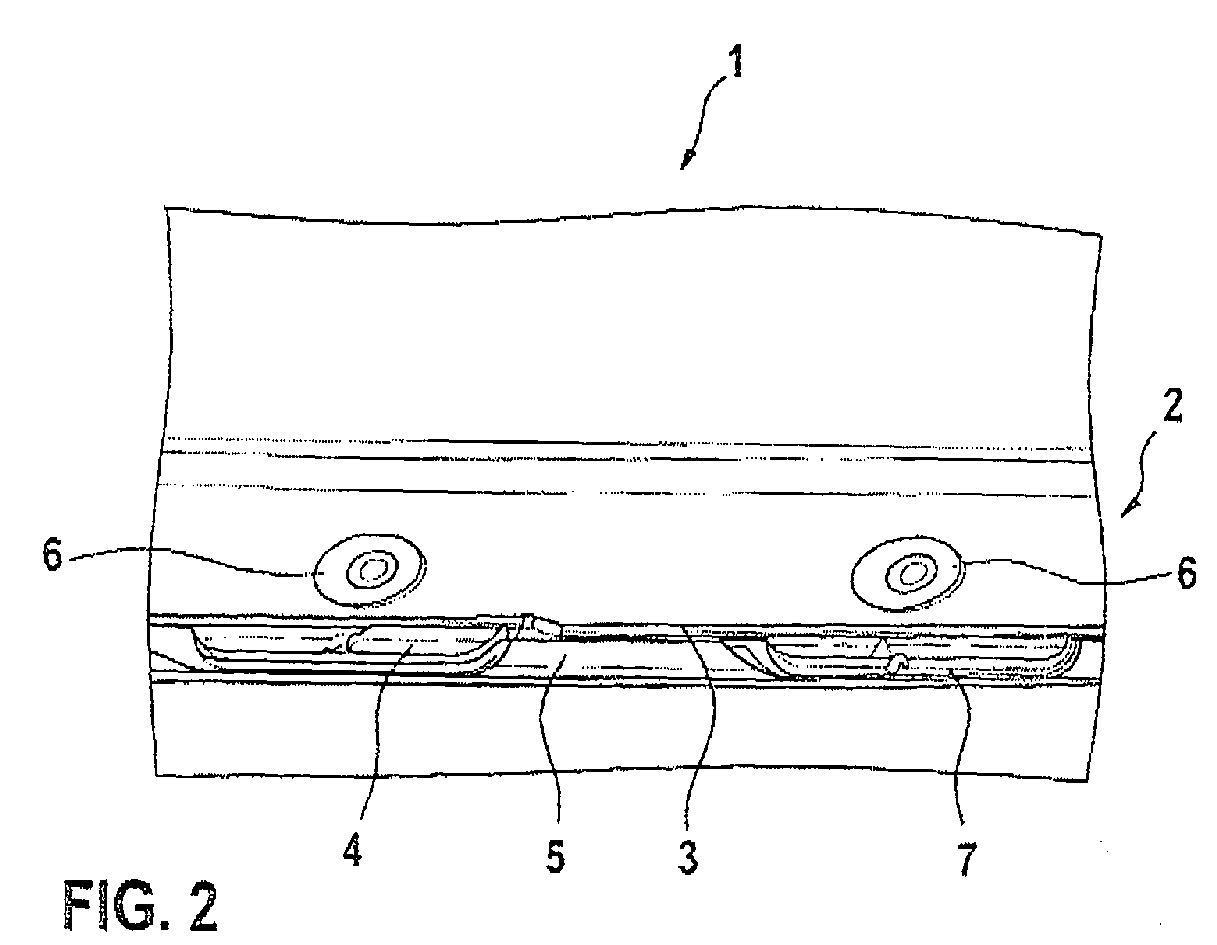
- FIG. 2 shows a photo of the welding region of the B-pillar 1 in an enlarged view.
- the B-pillar 1 has a flange 2, where a first sheet 3, a second sheet 4 and a third sheet 5 are welded together by spot welds 6. While the sheets 3 and 5 are made of thin DC04 according to EN 10130 material thickness 0.75 mm, the third, serving as reinforcement B-pillar plate 5 of 22 MnB5 and has a plate thickness of 1.7 mm.
- the second sheet 4 protrudes over the edge of the first sheet metal 3 in the area of the spot welds 6 and terminates flush with the edge of the third sheet metal 5. In the middle between the two spot welds, however, the second sheet 4 disappears below the first sheet 3 because it is narrower there. The edge 7 of the second sheet 4 thus projects further outward at the welds 6 than between the welds 6.
Landscapes
- Engineering & Computer Science (AREA)
- Mechanical Engineering (AREA)
- Chemical & Material Sciences (AREA)
- Combustion & Propulsion (AREA)
- Transportation (AREA)
- Architecture (AREA)
- Structural Engineering (AREA)
- Physics & Mathematics (AREA)
- Optics & Photonics (AREA)
- Body Structure For Vehicles (AREA)
Abstract
Die Erfindung betrifft einen Verbund, umfassend ein erstes Blech (3) und ein zweites Blech (4), bei dem die Bleche einen gemeinsamen Flansch (2) ausbilden, wo sie miteinander verschweißt sind, bei dem das zweite Blech aus einem gehärteten Stahl besteht, dessen Martensit- und/oder Bainitgehalt größer als 50 % und dessen Zugfestigkeit größer als 800 MPa ist, wobei der Rand (7) des zweiten Blechs im Flanschbereich an den Schweißstellen weiter nach draußen ragt als zwischen den Schweißstellen (6).The invention relates to a composite, comprising a first sheet (3) and a second sheet (4), in which the sheets form a common flange (2) where they are welded together, wherein the second sheet consists of a hardened steel, whose martensite and / or bainite content is greater than 50% and whose tensile strength is greater than 800 MPa, wherein the edge (7) of the second sheet in the flange at the welds protrudes farther out than between the welds (6).
Ein weiterer Aspekt der Erfindung betrifft ein Bauteil, beispielsweise eine Hochstrebe eines Pkw, das einen Verbund wie oben beschrieben umfasst.A further aspect of the invention relates to a component, for example a high strut of a passenger car, which comprises a composite as described above.
Ein dritter Aspekt der Erfindung betrifft eine B-Säule (1) für eine Ktz-Karosserie, umfassend eine Seitenwand innen (5), eine Seitenwand außen (3) und eine dazwischen befindliche Verstärkung B-Säule (4), wobei die beiden Seitenwände und die Verstärkung B-Säule einen gemeinsamen Flansch (2) ausbilden, wo sie miteinander verschweißt sind, bei dem die Verstärkung B-Säule ein Blech aus einem gehärteten Stahl ist, dessen Martensit und/oder Bainitanteil im Querschliff größer als 50 % ist und dessen Zugfestigkeit größer als 800 MPa ist, wobei der Rand (7) der Verstärkung B-Säule im Flanschbereich an den Schweißstellen (6) weiter nach draußen ragt als zwischen den Schweißstellen.
Description
Die Erfindung betrifft einen Verbund aus mindestens zwei Blechen sowie ein Bauteil, beispielsweise eine Hochstrebe eines Pkw, das diesen Verbund umfasst. Weiterhin betrifft die Erfindung eine B-Säule eines Kraftfahrzeugs.The invention relates to a composite of at least two sheets and a component, for example a high strut of a car, which comprises this composite. Furthermore, the invention relates to a B-pillar of a motor vehicle.
Bei der Herstellung von Kfz-Karosserien werden häufig Bleche aus gehärtetem Stahl eingesetzt, die entweder miteinander oder mit anderen Blechen verschweißt werden müssen. Die gehärteten Stähle dienen unter anderem dazu, den zunehmend strengeren Anforderungen gerecht zu werden, die zum Schutz der Fahrzeuginsassen erhoben werden. Zu diesem Zweck gibt es in den jeweiligen Staaten, in denen das Kraftfahrzeug zugelassen werden soll, standardisierte Aufpralltests, die ein Fahrzeugmodell vor der Zulassung bestehen muss, um zugelassen zu werden. In Europa sind dies beispielsweise die Tests nach Euro-NCAP (European New Car Assessment Programme).In the manufacture of motor vehicle bodies, hardened steel sheets are often used, which must be welded together or with other sheets. Among other things, the hardened steels serve to meet the increasingly stringent requirements imposed on vehicle occupants. For this purpose, in each of the states in which the motor vehicle is to be registered, there are standardized impact tests which a vehicle model must pass before being approved in order to be approved. In Europe, for example, these are the tests under Euro-NCAP (European New Car Assessment Program).
Es ist eine Aufgabe einer Ausführungsform der Erfindung, einen Verbund aus mindestens zwei miteinander verschweißten Blechen, von denen mindestens eines aus einem gehärteten Stahl besteht, bereitzustellen, dessen Verschweißung selbst einer extremen mechanischen Beanspruchung standhält.It is an object of one embodiment of the invention to provide a composite of at least two sheets welded together, at least one of which is made of a hardened steel, the welding of which withstands even extreme mechanical stress.
Die Aufgabe einer weiteren Ausführungsform besteht in der Bereitstellung eines Bauteils, das diesen Verbund umfasst.The object of a further embodiment is to provide a component comprising this composite.
Ferner besteht eine Aufgabe einer Ausführungsform der Erfindung darin, eine B-Säule für Kraftfahrzeuge, insbesondere Pkw, bereitzustellen, die bei einem Seitenaufprall einen verbesserten Fahrzeuginsassenschutz bietet.It is a further object of one embodiment of the invention to provide a B-pillar for motor vehicles, particularly passenger cars, which provides improved vehicle occupant protection in a side impact.
Die Lösung dieser Aufgaben erfolgt mit den Merkmalen der unabhängigen Ansprüche. Vorteilhafte Weiterbildungen und weitere Ausführungsformen ergeben sich mit den Merkmalen der abhängigen Ansprüche.The solution of these objects is achieved by the features of the independent claims. Advantageous developments and further embodiments will become apparent with the features of the dependent claims.
Ein erster Aspekt der Erfindung betrifft einen Verbund aus einem ersten und einem zweiten Blech. Bei diesem Verbund haben die Bleche einen gemeinsamen Flansch, wo sie miteinander verschweißt sind. Das zweite Blech besteht aus einem gehärteten Stahl, dessen Martensit- und/oder Bainitanteil im Querschliff größer als 50 % ist und dessen Zugfestigkeit größer als 800 MPa ist. Der Rand des zweiten Blechs ragt im Flanschbereich an den Schweißstellen weiter nach draußen als zwischen den Schweißstellen.A first aspect of the invention relates to a composite of a first and a second sheet. In this composite, the sheets have a common flange where they are welded together. The second sheet consists of a hardened steel whose martensite and / or bainite content in cross section is greater than 50% and whose tensile strength is greater than 800 MPa. The edge of the second sheet protrudes in the flange area at the welds to the outside than between the welds.
Der Verbund umfasst insofern ein Blech aus einem gehärteten Stahl der oben angegebenen Zusammensetzung. Bei seiner Herstellung wird dieser Stahl in einem bekannten Verfahren durch Wärmebehandlung mit schnellem Abkühlen gehärtet, wodurch sich ein Ungleichgewichtsgefüge einstellt, das den Stahl besonders hart macht. Wird ein derart gehärteter Stahl mit einem weiteren Blech verschweißt, so stellt der Schweißvorgang eine lokale Wärmebehandlung des Stahls dar, die das Gefüge im Schweißbereich erneut verändern kann. Wird die Schweißstelle nach der eigentlichen Schweißung rasch abgekühlt, wie es beispielsweise beim Punktschweißen mit wassergekühlten Schweißelektroden der Fall ist, wird das Material im Schweißfleck erneut ein Ungleichgewichtsgefüge mit der gewünschten Härte haben.The composite thus comprises a hardened steel sheet of the above composition. In its manufacture, this steel is hardened in a known process by heat treatment with rapid cooling, whereby an imbalance structure sets, which makes the steel particularly hard. If such a hardened steel is welded to another sheet, the welding process is a local heat treatment of the steel, which can change the structure in the welding area again. If the weld is cooled quickly after the actual welding, as for example when spot-welding with water-cooled welding electrodes, the material in the weld spot will again have an imbalance structure of the desired hardness.
Es wird vermutet, dass oftmals das Material in einem gewissen Randbereich des Schweißflecks, in der so genannten Wärmeeinflusszone, um den eigentlichen Schweißfleck herum nicht rasch abgekühlt wird. Das Material in der Wärmeeinflusszone würde somit durch die Schweißung stark erwärmt werden und dann mangels nachträglicher Kühlung nur langsam abkühlen. Metallurgische Untersuchungen haben ergeben, dass sich in der Wärmeeinflusszone ein weicheres Gefüge mit weniger oder gar keinem Ungleichgewichtsgefüge ausbildet. Der Stahl zeigt in dieser Wärmeeinflusszone eine geringere Härte als im Schweißfleck oder im Grundmaterial. Mit anderen Worten hat das zweite Blech in der Wärmeeinflusszone ein Härteminimum.It is believed that often the material in a certain edge region of the weld spot, in the so-called heat affected zone, is not rapidly cooled around the actual weld spot. The material in the heat-affected zone would thus be strongly heated by the weld and then cool only slowly for lack of subsequent cooling. Metallurgical investigations have shown that a softer structure with less or no imbalance structure is formed in the heat-affected zone. The steel has a lower hardness in this heat affected zone than in the weld spot or in the base material. In other words, the second sheet has a hardness minimum in the heat affected zone.
Wird ein Verbund, der einen derartigen Schweißbereich besitzt, einer extremen Zugbelastung ausgesetzt, so kommt es zu einem Fließen des Stahlmaterials. Wegen des Härteminimums wird es fast ausschließlich in der vorgenannten Wärmeeinflusszone zum Fließen kommen und sich dort ein Riss ausbilden, der sich anschließend durch das Grundmaterial fortpflanzt und insofern die Strukturstabilität des Verbunds begrenzt. Dasselbe gilt sinngemäß auch bei einer Biegebeanspruchung des Verbunds, die eine entsprechende Zugbelastung zur Folge hat.If a composite having such a weld area is subjected to an extreme tensile load, the steel material will flow. Because of the hardness minimum, it will flow almost exclusively in the aforementioned heat affected zone and form a crack there, which then propagates through the base material and thus limits the structural stability of the composite. The same applies mutatis mutandis to a bending stress of the composite, which has a corresponding tensile load.
Der Rissvermeidung dient eine Ausgestaltung des zweiten Blechs, bei der sein Rand im Flanschbereich an den Schweißstellen weiter nach draußen ragt als zwischen den Schweißstellen. Dadurch wird die Spannung an den Schweißstellen herabgesetzt und wird entsprechend ein Fließen des Grundmaterials zwischen den Schweißstellen gefördert.The crack prevention is an embodiment of the second sheet, in which its edge in the flange at the welds protrudes further outward than between the welds. As a result, the stress is reduced at the welds and is funded according to a flow of the base material between the welds.
Zur Bestimmung des Bainit- und/oder Martensitgehalts des zweiten Blechs wird ein Stück entnommen und so eingebettet, geschliffen und geätzt, dass man bei der Bestimmung auf den Querschnitt des zweiten Bleches blickt. Aufgrund des unterschiedlichen Ätzverhaltens der einzelnen Gefügebestandteile erkennt man die einzelnen Gefügebestandteile. Die einzelnen Gefügebestandteile sind dreidimensional, wobei Martensit und Bainit nadelförmig erscheinen. Der Flächenanteil im Schliff wird per Software durch Unterscheidung von Graustufen bestimmt. Hierzu kann das Programm "IMAGE C" der IMTRONIC GmbH, Berlin, eingesetzt werden. Eine lichtmikroskopische Zuordnung von Anteilen des Schliffbildes zu Bainit oder Martensit ist manchmal nicht möglich.To determine the bainite and / or martensite content of the second sheet, a piece is removed and so embedded, ground and etched that looks in the determination of the cross section of the second sheet. Due to the different etching behavior of the individual microstructure constituents, one recognizes the individual constituents of the microstructure. The individual structural components are three-dimensional, with martensite and bainite appearing like a needle. The surface area in the cut is determined by software by distinguishing gray levels. For this, the program "IMAGE C" of IMTRONIC GmbH, Berlin, can be used. A light microscopic assignment of proportions of the micrograph to bainite or martensite is sometimes not possible.
Aus den obigen Ausführungen ergibt sich, dass der Flansch nicht mit einer einzigen länglichen Schweißnaht versehen ist, sondern eine Mehrzahl lokaler, voneinander beabstandeter Schweißstellen besitzt. Es kann sich hierbei um voneinander beabstandete strichförmige Schweißungen oder um Punktschweißungen handeln. Handelt es sich um eine Sequenz von Schweißstellen, so wird der Flansch im Regelfall ein länglicher, bandförmiger Flansch sein.From the above, it can be seen that the flange is not provided with a single elongated weld, but has a plurality of local, spaced apart welds. These may be spaced-apart line-shaped welds or spot welds. If it is a sequence of welds, the flange will usually be an elongated, band-shaped flange.
Zwecks Gewichtsersparnis ist es gemäß einer zweiten Ausführungsform auch möglich, das erste Blech ebenfalls so auszugestalten, dass es an den Schweißstellen weiter nach draußen ragt als zwischen den Schweißstellen. In diesem Fall ergibt sich ein Flansch, der an den Schweißstellen breiter ist als zwischen den Schweißstellen.In order to save weight, it is also possible according to a second embodiment also to design the first sheet so that it protrudes further out at the welds than between the welds. In this case, there is a flange that is wider at the welds than between the welds.
In einer dritten Ausführungsform sind die Bleche über Punktschweißungen miteinander verschweißt.In a third embodiment, the sheets are welded together by spot welds.
In einer weiteren Ausführungsform ragt das zweite Blech an den Schweißstellen, z.B. den Schweißpunkten, ca. 1 mm bis ca. 3 mm weiter nach draußen als zwischen zwei Schweißstellen. Ragt er an den Schweißstellen weniger als 1 mm weiter nach draußen als zwischen den Schweißstellen, so ist die Spannung an der Schweißstelle zu groß. Bei mehr als 3 mm wird das Grundmaterial zwischen zwei Schweißstellen zu stark beansprucht. Beste Ergebnisse ergaben sich bei 2 mm +/- 0.5 mm.In a further embodiment, the second sheet protrudes at the welds, e.g. The welding points, about 1 mm to about 3 mm further out than between two welds. If it protrudes at the welds less than 1 mm further outward than between the welds, the tension at the weld is too great. If more than 3 mm, the base material between two welds is stressed too much. Best results were obtained at 2 mm +/- 0.5 mm.
Die oben genannte Anpassung des Rands des zweiten Blechs an die Orte der Schweißstellen kann gemäß einer weiteren Ausführungsform so realisiert werden, dass der Rand einen wellenförmigen Rand hat. Diese Ausführungsform ist bei regelmäßig gesetzten Punktschweißungen praktikabel.The above-mentioned adaptation of the edge of the second sheet to the locations of the welds can be realized according to a further embodiment in such a way that the edge has a wave-shaped edge. This embodiment is practicable with regularly set spot welds.
Gemäß dem oben gegebenen Erklärungsversuch für das Verhalten des Verbunds bei extremer mechanischer Beanspruchung im Bereich der Schweißstellen ergibt sich die Problematik der Gefügeveränderungen wegen Schweißoperationen bei gehärteten Stählen mit Ungleichgewichtsgefügen. Demgemäß kann das zweite Blech aus einem Verfügungsstahl, einem Dualphasenstahl, einem Komplexphasenstahl, einem TRIP-Stahl oder einem martensitischen Stahl bestehen. Der Vergütungsstahl kann zum Beispiel 22 MnB5 sein.According to the above explanatory test for the behavior of the composite under extreme mechanical stress in the area of the welds, the problem of structural changes due to welding operations in hardened steels with imbalance structures arises. Accordingly, the second plate may be made of a disposable steel, a dual-phase steel, a complex phase steel, a TRIP steel or a martensitic steel. For example, the tempered steel may be 22 MnB5.
In einer weiteren Ausführungsform umfasst der Verbund ein drittes Blech, wobei sich das zweite Blech zwischen dem ersten und dem dritten Blech befindet und bei dem die drei Bleche im gemeinsamen Flansch miteinander verschweißt sind. Die Schweißstellen sind hier 3-Blechschweißungen.In a further embodiment, the composite comprises a third sheet, wherein the second sheet is located between the first and the third sheet and in which the three sheets are welded together in the common flange. The welds here are 3-sheet metal welds.
Ein zweiter Aspekt der Erfindung betrifft ein Bauteil, das einen Verbund gemäß einer der oben beschriebenen Ausführungsformen umfasst. Das Bauteil kann eine Hochstrebe eines Pkw sein, d.h. eine A-, B- oder C-Säule. Bei solchen Hochstreben ist dies z.B. die Seitenwand außen mit einer Verstärkung und der Seitenwand innen verschweißt. Bei einer solchen 3-Blechschweißung im Sinne des letzten Absatzes besteht die Verstärkung. z.B. die Verstärkung B-Säule, oftmals aus einem gehärteten Stahl, damit die Karosserie die Euro-NCAP-Tests für den Seitenaufprall mit starrer Barriere besteht. Der gehärtete Stahl kann ein PHS-Stahl (englisch: press hardened steel) sein. Die Seitenwände außen und innen bestehen aus Bandstahl mit geringerer Zugfestigkeit.A second aspect of the invention relates to a component, which comprises a composite according to one of the embodiments described above. The component may be a high strut of a passenger car, ie an A, B or C pillar. In such high struts, for example, this is the side wall outside with a reinforcement and the side wall welded inside. In such a 3-sheet metal welding in the sense of the last paragraph, there is the reinforcement. For example, the reinforcement B-pillar, often made of hardened steel, so that the body consists of the Euro-NCAP tests for the side impact with a rigid barrier. The hardened steel may be a PHS (press hardened steel) steel. The side walls outside and inside are made of steel strip with lower tensile strength.
Ein dritter Aspekt betrifft eine B-Säule für eine Kfz-Karosserie. Die B-Säule umfasst eine Seitenwand innen, eine Seitenwand außen und eine dazwischen befindliche Verstärkung B-Säule. Die beiden genannten Seitenwände und die Verstärkung B-Säule bilden einen gemeinsamen Flansch aus, wo sie miteinander verschweißt sind. Die Schweißung ist damit eine 3-Blechschweißung. Die Verstärkung B-Säule ist ein Blech aus einem gehärteten Stahl, dessen Martensit- und/oder Bainitanteil im Querschliff größer als 50 % ist und dessen Zugfestigkeit größer als 800 MPa ist. Der gehärtete Stahl kann ein PHS-Stahl (englisch: press hardened steel) sein. Die Seitenwände außen und innen bestehen aus Bandstahl mit geringerer Zugfestigkeit. Der Rand der Verstärkung B-Säule im Flanschbereich ragt an den Schweißstellen weiter nach draußen als zwischen den Schweißstellen. Dies kann so realisiert werden, dass nicht nur die Verstärkung B-Säule, sondern der gesamte Flansch an den Schweißstellen breiter ist als zwischen den Schweißstellen. Der Rand der Verstärkung B-Säule oder der Rand des Flansches kann hierbei wellenförmig sein.A third aspect relates to a B-pillar for a motor vehicle body. The B-pillar includes a sidewall inside, a sidewall outside and a reinforcement B pillar in between. The two mentioned side walls and the reinforcement B-pillar form a common flange, where they are welded together. The weld is thus a 3-sheet metal weld. Reinforcement B-pillar is a sheet of hardened steel whose martensite and / or bainite content in cross section is greater than 50% and whose tensile strength is greater than 800 MPa. The hardened steel may be a PHS (press hardened steel) steel. The side walls outside and inside are made of steel strip with lower tensile strength. The edge of the reinforcement B-pillar in the flange area protrudes at the welds to the outside than between the welds. This can be realized so that not only the reinforcement B-pillar, but the entire flange at the welds is wider than between the welds. The edge of the reinforcement B-pillar or the edge of the flange can be wavy.
Weitere Merkmale und Vorteile der beanspruchten Erfindung werden aus der folgenden detaillierten Beschreibung mit Bezug auf die beigefügten Zeichnungen erkennbar, die nachfolgend als nicht beschränkende Beispiele angegeben sind. Hierbei soll die Benutzung von Bezugszeichen in den Figuren nicht dahingehend verstanden werden, dass die Bezugszeichen den Schutzumfang der beanspruchten Erfindung einschränken sollen. Es zeigen:
- Fig. 1
- eine B-Säule eines Pkw,
- Fig. 2
- eine Detailaufnahme eines Schweißbereichs.
- Fig. 1
- a B-pillar of a car,
- Fig. 2
- a detail of a welding area.
Bei den Figuren, die allgemein mit gleichen Bezugszeichen gleiche Gegenstände bezeichnen, zeigt Figur 1 eine B-Säule 1 eines Pkw. Zu seiner Herstellung wird eine Verstärkung B-Säule zwischen einer Seitenwand außen und einer Seitenwand innen platziert und die drei Bleche miteinander verschweißt.In the figures, which generally denote like objects by like reference numerals, Figure 1 shows a B-
Figur 2 zeigt ein Foto des Schweißbereichs der B-Säule 1 in einer vergrößerten Darstellung. Die B-Säule 1 besitzt einen Flansch 2, wo ein erstes Blech 3, ein zweites Blech 4 und ein drittes Blech 5 über Punktschweißungen 6 miteinander verschweißt sind. Während die Bleche 3 und 5 aus dünnem DC04 nach EN 10130 der Materialstärke 0,75 mm besteht ist das dritte, als Verstärkung B-Säule dienende Blech 5 aus 22 MnB5 und hat eine Blechstärke von 1,7 mm.FIG. 2 shows a photo of the welding region of the B-
Aus Figur 2 erkennt man, dass das zweite Blech 4 im Bereich der Punktschweißungen 6 über den Rand des ersten Blechs 3 hinausragt und bündig mit dem Rand des dritten Blechs 5 abschließt. In der Mitte zwischen den zwei Punktschweißungen hingegen verschwindet das zweite Blech 4 unter dem ersten Blech 3, weil es dort schmaler ist. Der Rand 7 des zweiten Blechs 4 ragt damit an den Schweißstellen 6 weiter nach draußen als zwischen den Schweißstellen 6.It can be seen from FIG. 2 that the
Obwohl vorstehend konkrete Ausführungsformen beschrieben wurden, wird der Fachmann erkennen, dass die Beschreibung dieser Ausführungsformen nicht zum Zweck hat, die Erfindung in der angegebenen Form zu beschränken. Die Erfindung soll vielmehr alle Modifikationen, Äquivalente und Alternativen umfassen, die in den Schutzumfang der beanspruchten Erfindung fallen.Although specific embodiments have been described above, it will be apparent to those skilled in the art that the description of these embodiments is not intended to limit the invention to the precise form disclosed. Rather, the invention is intended to embrace all modifications, equivalents and alternatives that fall within the scope of the claimed invention.
- 0101
- B-SäuleB-pillar
- 0202
- Flanschflange
- 0303
- erstes Blech / Seitenwand außenfirst sheet metal / side wall outside
- 0404
- zweites Blech / Verstärkung B-Säulesecond plate / reinforcement B-pillar
- 0505
- drittes Blech / Seitenwand innenthird sheet metal / side wall inside
- 0606
- Punktschweißungspot welding
- 0707
- Randedge
Claims (19)
Applications Claiming Priority (2)
| Application Number | Priority Date | Filing Date | Title |
|---|---|---|---|
| DE200610047582 DE102006047582A1 (en) | 2006-10-05 | 2006-10-05 | Structural member e.g. B-column for passenger car, has flange formed from spot welding together three sheet metals, with one of sheet metals made from hardened steel and having edges raised out from between spot welds |
| DE202006015367U DE202006015367U1 (en) | 2006-10-05 | 2006-10-05 | Connection for motor vehicle e.g. passenger car, has first sheet metal and second sheet metal whereby the sheet metals have common flange where they are welded with one another |
Publications (3)
| Publication Number | Publication Date |
|---|---|
| EP1908547A2 true EP1908547A2 (en) | 2008-04-09 |
| EP1908547A3 EP1908547A3 (en) | 2012-01-25 |
| EP1908547B1 EP1908547B1 (en) | 2013-01-16 |
Family
ID=38961882
Family Applications (1)
| Application Number | Title | Priority Date | Filing Date |
|---|---|---|---|
| EP07019556A Not-in-force EP1908547B1 (en) | 2006-10-05 | 2007-10-05 | Welded assembly of two metal sheets |
Country Status (1)
| Country | Link |
|---|---|
| EP (1) | EP1908547B1 (en) |
Cited By (2)
| Publication number | Priority date | Publication date | Assignee | Title |
|---|---|---|---|---|
| EP2509849B1 (en) | 2009-12-13 | 2017-01-25 | Gestamp HardTech AB | B-pillar for a vehicle |
| EP2886332B1 (en) * | 2013-12-20 | 2018-11-21 | ThyssenKrupp Steel Europe AG | Flat steel product, and method of producing a component of a motor vehicle body and of a motor vehicle body. |
Family Cites Families (4)
| Publication number | Priority date | Publication date | Assignee | Title |
|---|---|---|---|---|
| AT370357B (en) * | 1981-09-08 | 1983-03-25 | Steyr Daimler Puch Ag | WELDING CONNECTION FOR BODY PANELS |
| JP3196477B2 (en) * | 1993-11-04 | 2001-08-06 | トヨタ自動車株式会社 | Structure of car door opening |
| JP2003103377A (en) * | 2001-09-27 | 2003-04-08 | Nippon Steel Corp | Spot welding method for high strength plated steel sheet |
| DE102004054795B4 (en) * | 2004-11-12 | 2007-04-05 | Thyssenkrupp Automotive Ag | Process for the production of vehicle components and body component |
-
2007
- 2007-10-05 EP EP07019556A patent/EP1908547B1/en not_active Not-in-force
Cited By (3)
| Publication number | Priority date | Publication date | Assignee | Title |
|---|---|---|---|---|
| EP2509849B1 (en) | 2009-12-13 | 2017-01-25 | Gestamp HardTech AB | B-pillar for a vehicle |
| EP2886332B1 (en) * | 2013-12-20 | 2018-11-21 | ThyssenKrupp Steel Europe AG | Flat steel product, and method of producing a component of a motor vehicle body and of a motor vehicle body. |
| US10272644B2 (en) | 2013-12-20 | 2019-04-30 | Thyssenkrupp Steel Europe Ag | Sheet steel product, a steel component produced from such a sheet steel product, and body for a motor vehicle |
Also Published As
| Publication number | Publication date |
|---|---|
| EP1908547A3 (en) | 2012-01-25 |
| EP1908547B1 (en) | 2013-01-16 |
Similar Documents
| Publication | Publication Date | Title |
|---|---|---|
| DE102014008718B3 (en) | Tailored semi-finished product and motor vehicle component | |
| WO2008068346A2 (en) | Composite made of two steel sheets | |
| DE102009056443A1 (en) | Crashbox and method for its production | |
| DE9017895U1 (en) | Tubular steel profile for door reinforcement | |
| WO2004056619A1 (en) | Engine hood comprising a protective device for pedestrians | |
| DE102008044523A1 (en) | Warmumformprofile | |
| DE202020105963U1 (en) | Automotive component | |
| DE202009002575U1 (en) | Profile part as a body component of a motor vehicle | |
| WO2018158130A1 (en) | Flat steel semi-finished product, method for producing a component, and use thereof | |
| WO2016074666A1 (en) | Body- or chassis component of a motor vehicle with corrosion protection and production method therefor | |
| DE102004037789B3 (en) | Floor group for bodywork of vehicle has floor plate in form of one-piece deformed sheet, and regions of higher rigidity | |
| DE102021117570A1 (en) | Motor vehicle door ring system | |
| DE102016124931A1 (en) | Method for producing a one-piece reinforcement element for a side frame of a vehicle, reinforcement element for a side frame of a vehicle and vehicle | |
| DE102004044925B3 (en) | Floor structure for the body of a motor vehicle | |
| DE202013011800U1 (en) | Line-reinforced motor vehicle sheet, in particular body panel | |
| DE102023116669A1 (en) | Side impact beams for reinforcing a vehicle door | |
| EP1908547B1 (en) | Welded assembly of two metal sheets | |
| DE102010012831B4 (en) | transmission tunnel | |
| DE102023124896B4 (en) | underbody panel of a motor vehicle | |
| DE102015116186A1 (en) | Semi-finished product and method for producing a vehicle component, use of a semi-finished product and vehicle component | |
| DE102006047582A1 (en) | Structural member e.g. B-column for passenger car, has flange formed from spot welding together three sheet metals, with one of sheet metals made from hardened steel and having edges raised out from between spot welds | |
| EP4296377A1 (en) | Method for producing a one-piece press-hardened door ring for a motor vehicle, which has different sheet metal thicknesses and strengths | |
| DE202006015367U1 (en) | Connection for motor vehicle e.g. passenger car, has first sheet metal and second sheet metal whereby the sheet metals have common flange where they are welded with one another | |
| DE102013001999B4 (en) | Method for quality assurance of a supporting structure for a vehicle | |
| DE102017222240A1 (en) | Body component, method for producing a body component and vehicle body with body component |
Legal Events
| Date | Code | Title | Description |
|---|---|---|---|
| PUAI | Public reference made under article 153(3) epc to a published international application that has entered the european phase |
Free format text: ORIGINAL CODE: 0009012 |
|
| AK | Designated contracting states |
Kind code of ref document: A2 Designated state(s): AT BE BG CH CY CZ DE DK EE ES FI FR GB GR HU IE IS IT LI LT LU LV MC MT NL PL PT RO SE SI SK TR |
|
| AX | Request for extension of the european patent |
Extension state: AL BA HR MK RS |
|
| RAP1 | Party data changed (applicant data changed or rights of an application transferred) |
Owner name: GM GLOBAL TECHNOLOGY OPERATIONS LLC |
|
| PUAL | Search report despatched |
Free format text: ORIGINAL CODE: 0009013 |
|
| AK | Designated contracting states |
Kind code of ref document: A3 Designated state(s): AT BE BG CH CY CZ DE DK EE ES FI FR GB GR HU IE IS IT LI LT LU LV MC MT NL PL PT RO SE SI SK TR |
|
| AX | Request for extension of the european patent |
Extension state: AL BA HR MK RS |
|
| RIC1 | Information provided on ipc code assigned before grant |
Ipc: B62D 25/04 20060101ALI20111221BHEP Ipc: B23K 35/30 20060101ALI20111221BHEP Ipc: B23K 37/00 20060101ALI20111221BHEP Ipc: B62D 29/00 20060101ALI20111221BHEP Ipc: B62D 27/02 20060101ALI20111221BHEP Ipc: B23K 33/00 20060101AFI20111221BHEP |
|
| 17P | Request for examination filed |
Effective date: 20120725 |
|
| RIC1 | Information provided on ipc code assigned before grant |
Ipc: B23K 35/30 20060101ALI20120814BHEP Ipc: B23K 33/00 20060101AFI20120814BHEP Ipc: B62D 29/00 20060101ALI20120814BHEP Ipc: B23K 37/00 20060101ALI20120814BHEP Ipc: B62D 27/02 20060101ALI20120814BHEP Ipc: B62D 25/04 20060101ALI20120814BHEP |
|
| GRAP | Despatch of communication of intention to grant a patent |
Free format text: ORIGINAL CODE: EPIDOSNIGR1 |
|
| AKX | Designation fees paid |
Designated state(s): AT BE BG CH CY CZ DE DK EE ES FI FR GB GR HU IE IS IT LI LT LU LV MC MT NL PL PT RO SE SI SK TR |
|
| GRAS | Grant fee paid |
Free format text: ORIGINAL CODE: EPIDOSNIGR3 |
|
| GRAA | (expected) grant |
Free format text: ORIGINAL CODE: 0009210 |
|
| AK | Designated contracting states |
Kind code of ref document: B1 Designated state(s): AT BE BG CH CY CZ DE DK EE ES FI FR GB GR HU IE IS IT LI LT LU LV MC MT NL PL PT RO SE SI SK TR |
|
| REG | Reference to a national code |
Ref country code: GB Ref legal event code: FG4D Free format text: NOT ENGLISH |
|
| REG | Reference to a national code |
Ref country code: CH Ref legal event code: EP |
|
| REG | Reference to a national code |
Ref country code: IE Ref legal event code: FG4D Free format text: LANGUAGE OF EP DOCUMENT: GERMAN |
|
| REG | Reference to a national code |
Ref country code: AT Ref legal event code: REF Ref document number: 593608 Country of ref document: AT Kind code of ref document: T Effective date: 20130215 Ref country code: CH Ref legal event code: EP |
|
| REG | Reference to a national code |
Ref country code: DE Ref legal event code: R096 Ref document number: 502007011211 Country of ref document: DE Effective date: 20130307 |
|
| REG | Reference to a national code |
Ref country code: NL Ref legal event code: VDEP Effective date: 20130116 |
|
| REG | Reference to a national code |
Ref country code: LT Ref legal event code: MG4D |
|
| PG25 | Lapsed in a contracting state [announced via postgrant information from national office to epo] |
Ref country code: SE Free format text: LAPSE BECAUSE OF FAILURE TO SUBMIT A TRANSLATION OF THE DESCRIPTION OR TO PAY THE FEE WITHIN THE PRESCRIBED TIME-LIMIT Effective date: 20130116 Ref country code: LT Free format text: LAPSE BECAUSE OF FAILURE TO SUBMIT A TRANSLATION OF THE DESCRIPTION OR TO PAY THE FEE WITHIN THE PRESCRIBED TIME-LIMIT Effective date: 20130116 Ref country code: ES Free format text: LAPSE BECAUSE OF FAILURE TO SUBMIT A TRANSLATION OF THE DESCRIPTION OR TO PAY THE FEE WITHIN THE PRESCRIBED TIME-LIMIT Effective date: 20130427 Ref country code: BG Free format text: LAPSE BECAUSE OF FAILURE TO SUBMIT A TRANSLATION OF THE DESCRIPTION OR TO PAY THE FEE WITHIN THE PRESCRIBED TIME-LIMIT Effective date: 20130416 Ref country code: IS Free format text: LAPSE BECAUSE OF FAILURE TO SUBMIT A TRANSLATION OF THE DESCRIPTION OR TO PAY THE FEE WITHIN THE PRESCRIBED TIME-LIMIT Effective date: 20130516 |
|
| PG25 | Lapsed in a contracting state [announced via postgrant information from national office to epo] |
Ref country code: FI Free format text: LAPSE BECAUSE OF FAILURE TO SUBMIT A TRANSLATION OF THE DESCRIPTION OR TO PAY THE FEE WITHIN THE PRESCRIBED TIME-LIMIT Effective date: 20130116 Ref country code: SI Free format text: LAPSE BECAUSE OF FAILURE TO SUBMIT A TRANSLATION OF THE DESCRIPTION OR TO PAY THE FEE WITHIN THE PRESCRIBED TIME-LIMIT Effective date: 20130116 Ref country code: PL Free format text: LAPSE BECAUSE OF FAILURE TO SUBMIT A TRANSLATION OF THE DESCRIPTION OR TO PAY THE FEE WITHIN THE PRESCRIBED TIME-LIMIT Effective date: 20130116 Ref country code: GR Free format text: LAPSE BECAUSE OF FAILURE TO SUBMIT A TRANSLATION OF THE DESCRIPTION OR TO PAY THE FEE WITHIN THE PRESCRIBED TIME-LIMIT Effective date: 20130417 Ref country code: PT Free format text: LAPSE BECAUSE OF FAILURE TO SUBMIT A TRANSLATION OF THE DESCRIPTION OR TO PAY THE FEE WITHIN THE PRESCRIBED TIME-LIMIT Effective date: 20130516 Ref country code: LV Free format text: LAPSE BECAUSE OF FAILURE TO SUBMIT A TRANSLATION OF THE DESCRIPTION OR TO PAY THE FEE WITHIN THE PRESCRIBED TIME-LIMIT Effective date: 20130116 Ref country code: NL Free format text: LAPSE BECAUSE OF FAILURE TO SUBMIT A TRANSLATION OF THE DESCRIPTION OR TO PAY THE FEE WITHIN THE PRESCRIBED TIME-LIMIT Effective date: 20130116 |
|
| PG25 | Lapsed in a contracting state [announced via postgrant information from national office to epo] |
Ref country code: EE Free format text: LAPSE BECAUSE OF FAILURE TO SUBMIT A TRANSLATION OF THE DESCRIPTION OR TO PAY THE FEE WITHIN THE PRESCRIBED TIME-LIMIT Effective date: 20130116 Ref country code: RO Free format text: LAPSE BECAUSE OF FAILURE TO SUBMIT A TRANSLATION OF THE DESCRIPTION OR TO PAY THE FEE WITHIN THE PRESCRIBED TIME-LIMIT Effective date: 20130116 Ref country code: DK Free format text: LAPSE BECAUSE OF FAILURE TO SUBMIT A TRANSLATION OF THE DESCRIPTION OR TO PAY THE FEE WITHIN THE PRESCRIBED TIME-LIMIT Effective date: 20130116 Ref country code: CZ Free format text: LAPSE BECAUSE OF FAILURE TO SUBMIT A TRANSLATION OF THE DESCRIPTION OR TO PAY THE FEE WITHIN THE PRESCRIBED TIME-LIMIT Effective date: 20130116 Ref country code: SK Free format text: LAPSE BECAUSE OF FAILURE TO SUBMIT A TRANSLATION OF THE DESCRIPTION OR TO PAY THE FEE WITHIN THE PRESCRIBED TIME-LIMIT Effective date: 20130116 |
|
| PLBE | No opposition filed within time limit |
Free format text: ORIGINAL CODE: 0009261 |
|
| STAA | Information on the status of an ep patent application or granted ep patent |
Free format text: STATUS: NO OPPOSITION FILED WITHIN TIME LIMIT |
|
| PG25 | Lapsed in a contracting state [announced via postgrant information from national office to epo] |
Ref country code: CY Free format text: LAPSE BECAUSE OF FAILURE TO SUBMIT A TRANSLATION OF THE DESCRIPTION OR TO PAY THE FEE WITHIN THE PRESCRIBED TIME-LIMIT Effective date: 20130116 |
|
| 26N | No opposition filed |
Effective date: 20131017 |
|
| PG25 | Lapsed in a contracting state [announced via postgrant information from national office to epo] |
Ref country code: IT Free format text: LAPSE BECAUSE OF FAILURE TO SUBMIT A TRANSLATION OF THE DESCRIPTION OR TO PAY THE FEE WITHIN THE PRESCRIBED TIME-LIMIT Effective date: 20130116 |
|
| REG | Reference to a national code |
Ref country code: DE Ref legal event code: R097 Ref document number: 502007011211 Country of ref document: DE Effective date: 20131017 |
|
| BERE | Be: lapsed |
Owner name: GM GLOBAL TECHNOLOGY OPERATIONS LLC Effective date: 20131031 |
|
| PG25 | Lapsed in a contracting state [announced via postgrant information from national office to epo] |
Ref country code: MC Free format text: LAPSE BECAUSE OF FAILURE TO SUBMIT A TRANSLATION OF THE DESCRIPTION OR TO PAY THE FEE WITHIN THE PRESCRIBED TIME-LIMIT Effective date: 20130116 |
|
| REG | Reference to a national code |
Ref country code: CH Ref legal event code: PL |
|
| REG | Reference to a national code |
Ref country code: IE Ref legal event code: MM4A |
|
| PG25 | Lapsed in a contracting state [announced via postgrant information from national office to epo] |
Ref country code: CH Free format text: LAPSE BECAUSE OF NON-PAYMENT OF DUE FEES Effective date: 20131031 Ref country code: LI Free format text: LAPSE BECAUSE OF NON-PAYMENT OF DUE FEES Effective date: 20131031 |
|
| PG25 | Lapsed in a contracting state [announced via postgrant information from national office to epo] |
Ref country code: BE Free format text: LAPSE BECAUSE OF NON-PAYMENT OF DUE FEES Effective date: 20131031 |
|
| PG25 | Lapsed in a contracting state [announced via postgrant information from national office to epo] |
Ref country code: IE Free format text: LAPSE BECAUSE OF NON-PAYMENT OF DUE FEES Effective date: 20131005 |
|
| REG | Reference to a national code |
Ref country code: AT Ref legal event code: MM01 Ref document number: 593608 Country of ref document: AT Kind code of ref document: T Effective date: 20131005 |
|
| PG25 | Lapsed in a contracting state [announced via postgrant information from national office to epo] |
Ref country code: AT Free format text: LAPSE BECAUSE OF NON-PAYMENT OF DUE FEES Effective date: 20131005 |
|
| PG25 | Lapsed in a contracting state [announced via postgrant information from national office to epo] |
Ref country code: TR Free format text: LAPSE BECAUSE OF FAILURE TO SUBMIT A TRANSLATION OF THE DESCRIPTION OR TO PAY THE FEE WITHIN THE PRESCRIBED TIME-LIMIT Effective date: 20130116 |
|
| PG25 | Lapsed in a contracting state [announced via postgrant information from national office to epo] |
Ref country code: LU Free format text: LAPSE BECAUSE OF NON-PAYMENT OF DUE FEES Effective date: 20131005 Ref country code: HU Free format text: LAPSE BECAUSE OF FAILURE TO SUBMIT A TRANSLATION OF THE DESCRIPTION OR TO PAY THE FEE WITHIN THE PRESCRIBED TIME-LIMIT; INVALID AB INITIO Effective date: 20071005 |
|
| PG25 | Lapsed in a contracting state [announced via postgrant information from national office to epo] |
Ref country code: MT Free format text: LAPSE BECAUSE OF FAILURE TO SUBMIT A TRANSLATION OF THE DESCRIPTION OR TO PAY THE FEE WITHIN THE PRESCRIBED TIME-LIMIT Effective date: 20130116 |
|
| REG | Reference to a national code |
Ref country code: FR Ref legal event code: PLFP Year of fee payment: 10 |
|
| PGFP | Annual fee paid to national office [announced via postgrant information from national office to epo] |
Ref country code: FR Payment date: 20160919 Year of fee payment: 10 |
|
| PGFP | Annual fee paid to national office [announced via postgrant information from national office to epo] |
Ref country code: GB Payment date: 20161026 Year of fee payment: 10 |
|
| PGFP | Annual fee paid to national office [announced via postgrant information from national office to epo] |
Ref country code: DE Payment date: 20170927 Year of fee payment: 11 |
|
| GBPC | Gb: european patent ceased through non-payment of renewal fee |
Effective date: 20171005 |
|
| REG | Reference to a national code |
Ref country code: FR Ref legal event code: ST Effective date: 20180629 |
|
| PG25 | Lapsed in a contracting state [announced via postgrant information from national office to epo] |
Ref country code: GB Free format text: LAPSE BECAUSE OF NON-PAYMENT OF DUE FEES Effective date: 20171005 |
|
| PG25 | Lapsed in a contracting state [announced via postgrant information from national office to epo] |
Ref country code: FR Free format text: LAPSE BECAUSE OF NON-PAYMENT OF DUE FEES Effective date: 20171031 |
|
| REG | Reference to a national code |
Ref country code: DE Ref legal event code: R119 Ref document number: 502007011211 Country of ref document: DE |
|
| PG25 | Lapsed in a contracting state [announced via postgrant information from national office to epo] |
Ref country code: DE Free format text: LAPSE BECAUSE OF NON-PAYMENT OF DUE FEES Effective date: 20190501 |