EP1908540A1 - Molded product provided with protruding section - Google Patents
Molded product provided with protruding section Download PDFInfo
- Publication number
- EP1908540A1 EP1908540A1 EP06823191A EP06823191A EP1908540A1 EP 1908540 A1 EP1908540 A1 EP 1908540A1 EP 06823191 A EP06823191 A EP 06823191A EP 06823191 A EP06823191 A EP 06823191A EP 1908540 A1 EP1908540 A1 EP 1908540A1
- Authority
- EP
- European Patent Office
- Prior art keywords
- projecting portion
- cast product
- cast
- body portion
- ribs
- Prior art date
- Legal status (The legal status is an assumption and is not a legal conclusion. Google has not performed a legal analysis and makes no representation as to the accuracy of the status listed.)
- Withdrawn
Links
- 230000005540 biological transmission Effects 0.000 claims description 22
- 229910052782 aluminium Inorganic materials 0.000 claims description 4
- XAGFODPZIPBFFR-UHFFFAOYSA-N aluminium Chemical compound [Al] XAGFODPZIPBFFR-UHFFFAOYSA-N 0.000 claims description 4
- FYYHWMGAXLPEAU-UHFFFAOYSA-N Magnesium Chemical compound [Mg] FYYHWMGAXLPEAU-UHFFFAOYSA-N 0.000 claims description 3
- 229910052749 magnesium Inorganic materials 0.000 claims description 3
- 239000011777 magnesium Substances 0.000 claims description 3
- 229910052751 metal Inorganic materials 0.000 abstract description 22
- 239000002184 metal Substances 0.000 abstract description 22
- 238000005266 casting Methods 0.000 abstract description 13
- 230000002787 reinforcement Effects 0.000 abstract description 2
- 229910000838 Al alloy Inorganic materials 0.000 description 2
- 238000004512 die casting Methods 0.000 description 2
- 238000005461 lubrication Methods 0.000 description 2
- 229910000861 Mg alloy Inorganic materials 0.000 description 1
- 238000001816 cooling Methods 0.000 description 1
- 230000000694 effects Effects 0.000 description 1
- 238000000465 moulding Methods 0.000 description 1
- 230000007935 neutral effect Effects 0.000 description 1
Images



Classifications
-
- B—PERFORMING OPERATIONS; TRANSPORTING
- B22—CASTING; POWDER METALLURGY
- B22D—CASTING OF METALS; CASTING OF OTHER SUBSTANCES BY THE SAME PROCESSES OR DEVICES
- B22D17/00—Pressure die casting or injection die casting, i.e. casting in which the metal is forced into a mould under high pressure
-
- F—MECHANICAL ENGINEERING; LIGHTING; HEATING; WEAPONS; BLASTING
- F16—ENGINEERING ELEMENTS AND UNITS; GENERAL MEASURES FOR PRODUCING AND MAINTAINING EFFECTIVE FUNCTIONING OF MACHINES OR INSTALLATIONS; THERMAL INSULATION IN GENERAL
- F16H—GEARING
- F16H57/00—General details of gearing
- F16H57/02—Gearboxes; Mounting gearing therein
- F16H57/03—Gearboxes; Mounting gearing therein characterised by means for reinforcing gearboxes, e.g. ribs
-
- F—MECHANICAL ENGINEERING; LIGHTING; HEATING; WEAPONS; BLASTING
- F16—ENGINEERING ELEMENTS AND UNITS; GENERAL MEASURES FOR PRODUCING AND MAINTAINING EFFECTIVE FUNCTIONING OF MACHINES OR INSTALLATIONS; THERMAL INSULATION IN GENERAL
- F16H—GEARING
- F16H57/00—General details of gearing
- F16H57/02—Gearboxes; Mounting gearing therein
- F16H2057/02017—Gearboxes; Mounting gearing therein characterised by special features related to the manufacturing of the gear case, e.g. special adaptations for casting
-
- F—MECHANICAL ENGINEERING; LIGHTING; HEATING; WEAPONS; BLASTING
- F16—ENGINEERING ELEMENTS AND UNITS; GENERAL MEASURES FOR PRODUCING AND MAINTAINING EFFECTIVE FUNCTIONING OF MACHINES OR INSTALLATIONS; THERMAL INSULATION IN GENERAL
- F16H—GEARING
- F16H57/00—General details of gearing
- F16H57/02—Gearboxes; Mounting gearing therein
- F16H2057/02039—Gearboxes for particular applications
- F16H2057/02043—Gearboxes for particular applications for vehicle transmissions
- F16H2057/02047—Automatic transmissions
-
- Y—GENERAL TAGGING OF NEW TECHNOLOGICAL DEVELOPMENTS; GENERAL TAGGING OF CROSS-SECTIONAL TECHNOLOGIES SPANNING OVER SEVERAL SECTIONS OF THE IPC; TECHNICAL SUBJECTS COVERED BY FORMER USPC CROSS-REFERENCE ART COLLECTIONS [XRACs] AND DIGESTS
- Y10—TECHNICAL SUBJECTS COVERED BY FORMER USPC
- Y10T—TECHNICAL SUBJECTS COVERED BY FORMER US CLASSIFICATION
- Y10T74/00—Machine element or mechanism
- Y10T74/21—Elements
- Y10T74/2186—Gear casings
Definitions
- the present invention relates to a cast product having a projecting portion such as a case for an automatic transmission. More specifically, the present invention relates to a cast product with improved molten metal flow to a projecting portion.
- a case 30 of an automatic transmission i.e., an aluminum cast product
- an automatic transmission i.e., an aluminum cast product
- a projecting portion 31 for supporting an end of a manual shaft projects from a cylindrical body portion 32 and a back surface center portion of the projecting portion 31 is connected with the body portion 32 via one rib 33.
- the one rib 33 is inadequate to serve as a runner toward a tip end of the projecting portion 31 when the cast product undergoes die casting, and is a factor leading to the generation of a casting cavity.
- the case 30 of the transmission has a complicated shape and thin thickness. In locations where the flow of molten metal is insufficient, particularly around the projecting portion 31, it is necessary to improve the flow of molten metal in order to prevent the generation of a casting cavity.
- a cast product having a projecting portion according to the invention of claim 1 is a cast product having a projecting portion that projects from a body portion and is integratedly cast with the body portion.
- the cast product having a projecting portion is characterized in that a wall surface of the projecting portion is connected and integratedly cast with the body portion by means of a plurality of ribs.
- the cast product having a projecting portion according to claim 2 is characterized in that the lateral ribs on the two sides are inclined in mutually opposite directions with respect to the projecting portion such that a distance between the ribs increases farther away from the projecting portion.
- the cast product having a projecting portion according to claim 2 is characterized in that the lateral ribs on the two sides are inclined in mutually opposite directions with respect to the projecting portion such that a distance between the ribs increases farther away from the projecting portion.
- the cast product having a projecting portion according to any one of claims 1 to 3 is characterized in that the cast product is one of an aluminum and a magnesium die cast product.
- the cast product having a projecting portion according to any one of claims 1 to 4 is characterized in that the cast product is a case for a transmission.
- the cast product having a projecting portion according to claim 5 is characterized in that the body portion is a portion of the case for the transmission that accommodates a speed change mechanism of the transmission.
- the cast product having a projecting portion according to claim 5 or 6 is characterized in that the projecting portion is a support portion of a manual shaft that projects from the case for an automatic transmission.
- a body portion and a wall surface of a projecting portion of a cast product are connected by means of a plurality of ribs and integratedly cast. Therefore, molten metal can easily flow up to a tip end of the projecting portion passing through the plurality of ribs from the body portion, and as a result, the generation of a casting cavity at the tip end of the projecting portion can be reliably prevented. Furthermore, the strength of the projecting portion can be improved through reinforcement by means of the plurality of ribs.
- the lateral ribs on two sides are connected and integratedly cast with the body portion and both side edge portions of the projecting portion. Therefore, a flow of molten metal can be well supplied up to the tip end of the projecting portion, with the molten metal passing through the lateral ribs on the two sides, and as a result, the generation of a casting cavity at the tip end of the projecting portion can be reliably prevented.
- molten metal flows in from one lateral rib, and the molten metal flows out from another lateral rib. Therefore, a flow path of molten metal is formed that enables the realization of a smooth flow of molten metal.
- a projecting portion that projects from a body portion can be integratedly cast with the body portion without generating a casting cavity at a tip end of the projecting portion.
- a projecting portion that projects from a body portion can be integratedly cast with the body portion without generating a casting cavity at a tip end of the projecting portion.
- a projecting portion that projects from the body portion can be integratedly cast with the body portion without generating a casting cavity at a tip end of the projecting portion.
- a support portion of a manual shaft that projects from a body portion can be integratedly cast with the body portion without generating a casting cavity at a tip end of the support portion.
- reference numeral 10 denotes a case for an automatic transmission, which is achieved by die casting and molding an aluminum alloy.
- the automatic transmission is structured with a torque converter and a multi-speed change mechanism serially arranged on an axis.
- Accommodated within the case 10 are a plurality of planetary gears, a clutch, a brake, and the like. Engagement and disengagement of the clutch and the brake changes the power transmission path of the plurality of planetary gears, while the rotation of an input member is changed to a plurality of speeds and transmitted to an output member.
- the case 10 may be cast using another metal such as a magnesium alloy.
- the case 10 is integratedly cast with a cylindrical body portion 11 and a lower chamber portion 12.
- the body portion 11 includes the plurality of planetary gears, the clutch, the brake, and the like, which act as a speed change mechanism of the transmission.
- the lower chamber portion 12 accommodates a valve body, i.e., a control instrument, and accumulates lubrication oil.
- a side of the case 10 is integratedly cast such that a tab-like projecting portion 13 that faces a side wall 12a of the lower chamber portion 12 projects from the body portion 11 into the lower chamber portion 12.
- a tip end portion of the projecting portion 13 is provided with a machined hole 16.
- Both side edge portions of the projecting portion 13 and the body portion 11 are respectively connected by lateral ribs 15a, 15b and integratedly cast.
- the lateral ribs 15a, 15b have a generally triangular shape.
- the respective lateral ribs 15a, 15b are integratedly joined on one side with the projecting portion 13 along a wall surface from respective lateral portions of the machined hole 16 of the projecting portion 13 tip end, while another side is integratedly joined with the body portion 11.
- the lateral ribs 15a, 15b are inclined in mutually opposite directions with respect to the projecting portion 13 such that a distance between the ribs increases farther away from the projecting portion 13.
- a center rib 15c with a generally triangular shape is disposed between the lateral rib 15a and the lateral rib 15b.
- One side of the center rib 15c is integratedly joined with the projecting portion 13 along a wall surface in front of the machined hole 16, while another side is integratedly joined with the body portion 11.
- the machined hole 16 of the projecting portion 13 is mechanically machined to serve as the machined hole 16 that supports a manual shaft.
- a manual shaft 18 is rotatably fitted and supported in the machined hole 16 and a through hole 17 provided in a side wall of the lower chamber portion 12.
- the manual shaft 18 is connected with a select lever by means of a linkage mechanism.
- the manual shaft 18 rotates in accordance with the shifting of the select lever to parking P, reverse R, neutral N, and drive D.
- a manual valve within a valve body (not shown) is switched via a lever and a rod, or a parking pole is engaged or disengaged with a parking gear.
- an opening 19 is provided that runs through the lower chamber portion 12 and an internal portion of the cylindrical body portion 11.
- the manual shaft 18 is connected with a parking rod whereby the parking pole is engaged to and disengaged from the parking gear via a detent lever (not shown).
- the case 10 is cast by injecting a molten aluminum alloy at a predetermined pressure into a die formed with a cavity corresponding to a thickness portion of the case 10. Subsequent to cooling, the die is opened and the case 10, i.e., the case product, is extracted. As FIGS. 1 and 3 show, the case 10 is cast with an orientation such that the projecting portion 13 extends in the horizontal direction, and the center rib 15c extends vertically upward from the projecting portion 13. The opening 19 is thus positioned downward of the projecting portion 13. As a consequence, there is insufficient flow of molten metal from the thin cylindrical body portion 11 with a wide surface area toward the projecting portion 13.
- the molten metal may flow from the body portion 11, past the lateral ribs 15a, 15b, and then flow from respective lateral portions of a section corresponding to the side edge portion of the projecting portion 13 and the machined hole 16 of the tip end portion, and flow in or out closer to the tip end than a section corresponding to the machined hole 16.
- molten metal flowing in from the lateral rib 15a and molten metal flowing out from the lateral rib 15b forms a flow path of molten metal.
- the molten metal also passes the center rib 15c and flows into or out of a center portion of the projecting portion 13.
- FIG. 5 is a partial enlarged cross-sectional view taken along a line 5-5 in FIG. 1 .
- This drawing shows a cross section of an oil surface sensor seat portion 20 for attaching an oil surface sensor, which detects an oil surface level of lubrication oil accumulated in the lower chamber portion 12.
- the oil surface sensor seat portion 20 is formed such that a portion of a side wall of the lower chamber portion 12 is parallel to a lower surface of the lower chamber portion 12 and projects outward partway.
- a cored hole 21 that is generally parallel to the side wall 12a of the lower chamber portion 12 from inside the lower chamber portion 12.
- the cored hole 21 and an upper surface of the oil surface sensor seat portion 20 are mechanically machined, and an oil surface sensor is attached to the oil surface sensor seat portion 20 with a tip end portion of the oil surface sensor inserted inside the lower chamber portion 12.
- an oil surface sensor seat portion 25 shown in FIG. 7 is inclined with respect to a lower surface of the lower chamber portion 12. Therefore, an upper portion of an outer side surface 25a of the oil surface sensor seat portion 25 protrudes outward.
- an outer side wall surface 26a of a cored hole 26 is inclined in a direction away from the side wall 12a of the lower chamber portion 12 and faces upward so as to enable die release. Therefore, a thickness 27 between the outer side surface 25a of the oil surface sensor seat portion 25 and the outer side wall surface 26a of the cored hole 26 is upwardly thicker and becomes a factor leading to the generation of a casting cavity.
- the above-described oil surface sensor seat portion 20 is formed parallel to a lower surface. Therefore, an outer side surface 20a of the oil surface sensor seat portion 20 is generally parallel to the side wall 12a of the lower chamber portion 12.
- a thickness 22 between an outer side wall surface 21 a of the cored hole 21 and the outer side surface 20a of the oil surface sensor seat portion 20 is uniform, and enables improved castability while preventing the generation of a casting cavity.
- a cast product having a projecting portion according to the present invention is applicable for use as a cast product having a projecting portion such as a case for an automatic transmission, wherein a projecting portion for supporting a tip end of a manual shaft projects from a cylindrical body portion.
Landscapes
- Engineering & Computer Science (AREA)
- General Engineering & Computer Science (AREA)
- Mechanical Engineering (AREA)
- General Details Of Gearings (AREA)
- Molds, Cores, And Manufacturing Methods Thereof (AREA)
Abstract
In a cast product having a projecting portion that projects from a body portion and is integratedly cast with the body portion, a wall surface of the projecting portion is connected and integratedly cast with the body portion by means of a plurality of ribs. By this configuration, molten metal can easily flow up to a tip end of the projecting portion passing through the plurality of ribs from the body portion, and as a result, the generation of a casting cavity at the tip end of the projecting portion can be prevented. Furthermore, the strength of the projecting portion can be improved through reinforcement by means of the plurality of ribs.
Description
- The present invention relates to a cast product having a projecting portion such as a case for an automatic transmission. More specifically, the present invention relates to a cast product with improved molten metal flow to a projecting portion.
- As
FIG. 6 shows, acase 30 of an automatic transmission, i.e., an aluminum cast product, is integratedly cast such that a projectingportion 31 for supporting an end of a manual shaft projects from acylindrical body portion 32 and a back surface center portion of the projectingportion 31 is connected with thebody portion 32 via onerib 33. - With a cast product that provides the one
rib 33 on the back surface center portion of the projectingportion 31 in this manner, however, the onerib 33 is inadequate to serve as a runner toward a tip end of the projectingportion 31 when the cast product undergoes die casting, and is a factor leading to the generation of a casting cavity. Furthermore, thecase 30 of the transmission has a complicated shape and thin thickness. In locations where the flow of molten metal is insufficient, particularly around the projectingportion 31, it is necessary to improve the flow of molten metal in order to prevent the generation of a casting cavity. - It is an object of the present invention to provide a cast product having a projecting portion, wherein molten metal easily flows to the projecting portion to prevent the generation of a casting cavity, and the strength of the projecting portion is increased.
- In order to achieve the above object, a cast product having a projecting portion according to the invention of claim 1 is a cast product having a projecting portion that projects from a body portion and is integratedly cast with the body portion. The cast product having a projecting portion is characterized in that a wall surface of the projecting portion is connected and integratedly cast with the body portion by means of a plurality of ribs.
- According to the invention of
claim 2, the cast product having a projecting portion according toclaim 2 is characterized in that the lateral ribs on the two sides are inclined in mutually opposite directions with respect to the projecting portion such that a distance between the ribs increases farther away from the projecting portion. - According to the invention of claim 3, the cast product having a projecting portion according to
claim 2 is characterized in that the lateral ribs on the two sides are inclined in mutually opposite directions with respect to the projecting portion such that a distance between the ribs increases farther away from the projecting portion. - According to the invention of claim 4, the cast product having a projecting portion according to any one of claims 1 to 3 is characterized in that the cast product is one of an aluminum and a magnesium die cast product.
- According to the invention of claim 5, the cast product having a projecting portion according to any one of claims 1 to 4 is characterized in that the cast product is a case for a transmission.
- According to the invention of claim 6, the cast product having a projecting portion according to claim 5 is characterized in that the body portion is a portion of the case for the transmission that accommodates a speed change mechanism of the transmission.
- According to the invention of claim 7, the cast product having a projecting portion according to claim 5 or 6 is characterized in that the projecting portion is a support portion of a manual shaft that projects from the case for an automatic transmission.
- According to the structure of the present invention, a body portion and a wall surface of a projecting portion of a cast product are connected by means of a plurality of ribs and integratedly cast. Therefore, molten metal can easily flow up to a tip end of the projecting portion passing through the plurality of ribs from the body portion, and as a result, the generation of a casting cavity at the tip end of the projecting portion can be reliably prevented. Furthermore, the strength of the projecting portion can be improved through reinforcement by means of the plurality of ribs.
- According to the invention of
claim 2, the lateral ribs on two sides are connected and integratedly cast with the body portion and both side edge portions of the projecting portion. Therefore, a flow of molten metal can be well supplied up to the tip end of the projecting portion, with the molten metal passing through the lateral ribs on the two sides, and as a result, the generation of a casting cavity at the tip end of the projecting portion can be reliably prevented. - According to the invention of claim 3, among the lateral ribs on the two sides, molten metal flows in from one lateral rib, and the molten metal flows out from another lateral rib. Therefore, a flow path of molten metal is formed that enables the realization of a smooth flow of molten metal.
- According to the invention of claim 4, with an aluminum or magnesium die cast product having a complicated shape and a thin thickness, a projecting portion that projects from a body portion can be integratedly cast with the body portion without generating a casting cavity at a tip end of the projecting portion.
- According to the invention of claim 5, with a case for a transmission, which is a cast product having a complicated shape and a thin thickness, a projecting portion that projects from a body portion can be integratedly cast with the body portion without generating a casting cavity at a tip end of the projecting portion.
- According to the invention of claim 6, with a case for an automatic transmission having a thin thickness and whose body portion has a wide surface area, a projecting portion that projects from the body portion can be integratedly cast with the body portion without generating a casting cavity at a tip end of the projecting portion.
- According to the invention of claim 7, with a case for an automatic transmission, which is a cast product having a complicated shape and a thin thickness, a support portion of a manual shaft that projects from a body portion can be integratedly cast with the body portion without generating a casting cavity at a tip end of the support portion.
-
- [
FIG. 1 ]
FIG. 1 is a drawing showing a case for an automatic transmission, which is a cast product having a projecting portion according to an embodiment of the present invention. - [
FIG. 2 ]
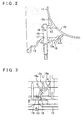
FIG. 2 is a drawing adding a manual shaft to an enlarged cross-sectional view taken along a line 2-2 inFIG. 1 . - [
FIG. 3 ]
FIG. 3 is an enlarged view of a section in the vicinity of the projecting portion inFIG. 1 . - [
FIG. 4 ]
FIG. 4 is a partial cross-sectional view taken along a line 4-4 inFIG. 3 . - [
FIG. 5 ]
FIG. 5 is a partial enlarged cross-sectional view taken along a line 5-5 inFIG. 1 . - [
FIG. 6 ]
FIG. 6 is a drawing showing a section in the vicinity of a projecting portion of a case in a conventional automatic transmission. - [
FIG. 7 ]
FIG. 7 is a drawing showing a molten metal surface sensor seat portion of a case in a conventional automatic transmission. -
- 10
- CASE
- 11
- BODY PORTION
- 12
- LOWER CHAMBER PORTION
- 13
- PROJECTING PORTION
- 14,21,26
- CORED HOLE
- 15a, 15b
- LATERAL RIB
- 15c
- CENTER RIB
- 18
- MANUAL SHAFT
- 19
- OPENING
- 20, 25
- OIL SURFACE SENSOR SEAT PORTION
- An embodiment of a cast product having a projecting portion according to the present invention will be described below based on the drawings. In
FIG. 1 ,reference numeral 10 denotes a case for an automatic transmission, which is achieved by die casting and molding an aluminum alloy. The automatic transmission is structured with a torque converter and a multi-speed change mechanism serially arranged on an axis. Accommodated within thecase 10 are a plurality of planetary gears, a clutch, a brake, and the like. Engagement and disengagement of the clutch and the brake changes the power transmission path of the plurality of planetary gears, while the rotation of an input member is changed to a plurality of speeds and transmitted to an output member. Thecase 10 may be cast using another metal such as a magnesium alloy. - As
FIGS. 2 to 4 show, thecase 10 is integratedly cast with acylindrical body portion 11 and alower chamber portion 12. Thebody portion 11 includes the plurality of planetary gears, the clutch, the brake, and the like, which act as a speed change mechanism of the transmission. Thelower chamber portion 12 accommodates a valve body, i.e., a control instrument, and accumulates lubrication oil. A side of thecase 10 is integratedly cast such that a tab-like projectingportion 13 that faces aside wall 12a of thelower chamber portion 12 projects from thebody portion 11 into thelower chamber portion 12. A tip end portion of the projectingportion 13 is provided with amachined hole 16. - Both side edge portions of the projecting
portion 13 and thebody portion 11 are respectively connected bylateral ribs lateral ribs lateral ribs portion 13 along a wall surface from respective lateral portions of the machinedhole 16 of the projectingportion 13 tip end, while another side is integratedly joined with thebody portion 11. Thelateral ribs portion 13 such that a distance between the ribs increases farther away from the projectingportion 13. Acenter rib 15c with a generally triangular shape is disposed between thelateral rib 15a and thelateral rib 15b. One side of thecenter rib 15c is integratedly joined with the projectingportion 13 along a wall surface in front of the machinedhole 16, while another side is integratedly joined with thebody portion 11. - The machined
hole 16 of the projectingportion 13 is mechanically machined to serve as the machinedhole 16 that supports a manual shaft. Amanual shaft 18 is rotatably fitted and supported in the machinedhole 16 and a throughhole 17 provided in a side wall of thelower chamber portion 12. Themanual shaft 18 is connected with a select lever by means of a linkage mechanism. Themanual shaft 18 rotates in accordance with the shifting of the select lever to parking P, reverse R, neutral N, and drive D. Depending on such rotation, a manual valve within a valve body (not shown) is switched via a lever and a rod, or a parking pole is engaged or disengaged with a parking gear. Between the projectingportion 13 and theside wall 12a of thelower chamber portion 12, anopening 19 is provided that runs through thelower chamber portion 12 and an internal portion of thecylindrical body portion 11. Themanual shaft 18 is connected with a parking rod whereby the parking pole is engaged to and disengaged from the parking gear via a detent lever (not shown). - The
case 10 is cast by injecting a molten aluminum alloy at a predetermined pressure into a die formed with a cavity corresponding to a thickness portion of thecase 10. Subsequent to cooling, the die is opened and thecase 10, i.e., the case product, is extracted. AsFIGS. 1 and3 show, thecase 10 is cast with an orientation such that the projectingportion 13 extends in the horizontal direction, and thecenter rib 15c extends vertically upward from the projectingportion 13. Theopening 19 is thus positioned downward of the projectingportion 13. As a consequence, there is insufficient flow of molten metal from the thincylindrical body portion 11 with a wide surface area toward the projectingportion 13. However, in addition to flowing directly from thebody portion 11 to the projectingportion 13, the molten metal may flow from thebody portion 11, past thelateral ribs portion 13 and the machinedhole 16 of the tip end portion, and flow in or out closer to the tip end than a section corresponding to the machinedhole 16. For example, molten metal flowing in from thelateral rib 15a and molten metal flowing out from thelateral rib 15b forms a flow path of molten metal. Moreover, the molten metal also passes thecenter rib 15c and flows into or out of a center portion of the projectingportion 13. As such, a flow path of molten metal is formed by thelateral ribs center rib 15c with respect to the projectingportion 13. Therefore, a smooth flow path of molten metal can be formed. Thus, the generation of a casting cavity at the tip end of the projectingportion 13 can be prevented, and the use of a plurality of ribs to reinforce the projectingportion 13 makes it possible to improve the strength of the projectingportion 13. -
FIG. 5 is a partial enlarged cross-sectional view taken along a line 5-5 inFIG. 1 . This drawing shows a cross section of an oil surfacesensor seat portion 20 for attaching an oil surface sensor, which detects an oil surface level of lubrication oil accumulated in thelower chamber portion 12. The oil surfacesensor seat portion 20 is formed such that a portion of a side wall of thelower chamber portion 12 is parallel to a lower surface of thelower chamber portion 12 and projects outward partway. Provided in the oil surfacesensor seat portion 20 is a coredhole 21 that is generally parallel to theside wall 12a of thelower chamber portion 12 from inside thelower chamber portion 12. The coredhole 21 and an upper surface of the oil surfacesensor seat portion 20 are mechanically machined, and an oil surface sensor is attached to the oil surfacesensor seat portion 20 with a tip end portion of the oil surface sensor inserted inside thelower chamber portion 12. - Conventionally, an oil surface
sensor seat portion 25 shown inFIG. 7 is inclined with respect to a lower surface of thelower chamber portion 12. Therefore, an upper portion of anouter side surface 25a of the oil surfacesensor seat portion 25 protrudes outward. In addition, an outerside wall surface 26a of a coredhole 26 is inclined in a direction away from theside wall 12a of thelower chamber portion 12 and faces upward so as to enable die release. Therefore, athickness 27 between theouter side surface 25a of the oil surfacesensor seat portion 25 and the outerside wall surface 26a of the coredhole 26 is upwardly thicker and becomes a factor leading to the generation of a casting cavity. - On the contrary, according to the present embodiment, the above-described oil surface
sensor seat portion 20 is formed parallel to a lower surface. Therefore, anouter side surface 20a of the oil surfacesensor seat portion 20 is generally parallel to theside wall 12a of thelower chamber portion 12. Thus, athickness 22 between an outer side wall surface 21 a of the coredhole 21 and theouter side surface 20a of the oil surfacesensor seat portion 20 is uniform, and enables improved castability while preventing the generation of a casting cavity. - A cast product having a projecting portion according to the present invention is applicable for use as a cast product having a projecting portion such as a case for an automatic transmission, wherein a projecting portion for supporting a tip end of a manual shaft projects from a cylindrical body portion.
Claims (7)
- A cast product having a projecting portion that projects from a body portion and is integratedly cast with the body portion, the cast product having a projecting portion characterized in that a wall surface of the projecting portion is connected and integratedly cast with the body portion by means of a plurality of ribs.
- The cast product having a projecting portion according to claim 1, characterized in that the plurality of ribs are lateral ribs on two sides which are connected and integratedly cast with the body portion and both side edge portions of the projecting portion.
- The cast product having a projecting portion according to claim 2, characterized in that the lateral ribs on the two sides are inclined in mutually opposite directions with respect to the projecting portion such that a distance between the ribs increases farther away from the projecting portion.
- The cast product having a projecting portion according to any one of claims 1 to 3, characterized in that the cast product is one of an aluminum and a magnesium die cast product.
- The cast product having a projecting portion according to any one of claims 1 to 4, characterized in that the cast product is a case for a transmission.
- The cast product having a projecting portion according to claim 5, characterized in that the body portion is a portion of the case for the transmission that accommodates a speed change mechanism of the transmission.
- The cast product having a projecting portion according to claim 5 or 6, characterized in that the projecting portion is a support portion of a manual shaft that projects from the case for an automatic transmission.
Applications Claiming Priority (2)
| Application Number | Priority Date | Filing Date | Title |
|---|---|---|---|
| JP2005323685A JP2007130643A (en) | 2005-11-08 | 2005-11-08 | Casting product with protrusions |
| PCT/JP2006/322287 WO2007055246A1 (en) | 2005-11-08 | 2006-11-08 | Molded product provided with protruding section |
Publications (1)
| Publication Number | Publication Date |
|---|---|
| EP1908540A1 true EP1908540A1 (en) | 2008-04-09 |
Family
ID=38023248
Family Applications (1)
| Application Number | Title | Priority Date | Filing Date |
|---|---|---|---|
| EP06823191A Withdrawn EP1908540A1 (en) | 2005-11-08 | 2006-11-08 | Molded product provided with protruding section |
Country Status (5)
| Country | Link |
|---|---|
| US (1) | US20090241726A1 (en) |
| EP (1) | EP1908540A1 (en) |
| JP (1) | JP2007130643A (en) |
| CN (1) | CN101247909A (en) |
| WO (1) | WO2007055246A1 (en) |
Families Citing this family (2)
| Publication number | Priority date | Publication date | Assignee | Title |
|---|---|---|---|---|
| JP4959467B2 (en) * | 2007-08-20 | 2012-06-20 | アイシン・エィ・ダブリュ株式会社 | Transmission case |
| JP5315370B2 (en) * | 2011-03-02 | 2013-10-16 | ジヤトコ株式会社 | Mold for casting |
Family Cites Families (10)
| Publication number | Priority date | Publication date | Assignee | Title |
|---|---|---|---|---|
| US4040821A (en) * | 1975-08-22 | 1977-08-09 | Ford Motor Company | Nodularizing catalyst for cast iron and method of making same |
| JP3183114B2 (en) * | 1995-08-30 | 2001-07-03 | トヨタ自動車株式会社 | Hollow tube casting method and apparatus |
| JP2000104827A (en) * | 1998-09-30 | 2000-04-11 | Fuji Heavy Ind Ltd | Parking device for continuously variable transmission |
| JP2001121248A (en) * | 1999-10-27 | 2001-05-08 | Mitsuba Corp | Casting method and casting mold for housing for electric power steering device |
| JP2002045956A (en) * | 2000-05-22 | 2002-02-12 | Hitachi Ltd | Electronic device housing and method of manufacturing the same |
| US6672650B2 (en) * | 2001-04-11 | 2004-01-06 | Patent Holding Company | Plastic panel with integrally molded speaker grille |
| JP2003062642A (en) * | 2001-08-24 | 2003-03-05 | Aisin Seiki Co Ltd | Master cylinder body and molding die for master cylinder body |
| JP2003285150A (en) * | 2002-03-27 | 2003-10-07 | Honda Motor Co Ltd | Die casting with rib |
| US6676427B2 (en) * | 2002-05-28 | 2004-01-13 | Speed Tech Corp. | Housing structure of a connector |
| JP2006528756A (en) * | 2003-05-22 | 2006-12-21 | ダイムラークライスラー・アクチェンゲゼルシャフト | Transmission housing |
-
2005
- 2005-11-08 JP JP2005323685A patent/JP2007130643A/en active Pending
-
2006
- 2006-11-08 EP EP06823191A patent/EP1908540A1/en not_active Withdrawn
- 2006-11-08 CN CNA200680031050XA patent/CN101247909A/en active Pending
- 2006-11-08 WO PCT/JP2006/322287 patent/WO2007055246A1/en not_active Ceased
- 2006-11-08 US US11/990,688 patent/US20090241726A1/en not_active Abandoned
Non-Patent Citations (1)
| Title |
|---|
| See references of WO2007055246A1 * |
Also Published As
| Publication number | Publication date |
|---|---|
| US20090241726A1 (en) | 2009-10-01 |
| CN101247909A (en) | 2008-08-20 |
| WO2007055246A1 (en) | 2007-05-18 |
| JP2007130643A (en) | 2007-05-31 |
Similar Documents
| Publication | Publication Date | Title |
|---|---|---|
| US4231266A (en) | Lubricating device for power transmission unit | |
| JP4640250B2 (en) | Transmission control device for twin-clutch automatic manual transmission | |
| CA2584642A1 (en) | Hybrid motor vehicle with sequential gearshift lever | |
| US8360915B2 (en) | Axle | |
| JP6365827B2 (en) | Transmission lubrication structure | |
| US20090241726A1 (en) | Molded product provided with protruding section | |
| EP1801461A2 (en) | Lubricating structure for transmission | |
| US20200263781A1 (en) | Drive force transmission device and method for manufacturing same | |
| US20100327210A1 (en) | Control valve body of automatic transmission and manufacturing method therefor | |
| US5800126A (en) | Swinging head gear shell of an electric fan | |
| CN210566190U (en) | A transmission single shift fork shaft assembly structure | |
| US20250122910A1 (en) | Input drum assembly for improving performance of 68rfe transmission, 68rfe transmission, and method | |
| JP4670708B2 (en) | Automatic transmission | |
| JP5800401B2 (en) | transmission | |
| KR100968759B1 (en) | Case of dual clutch gearbox | |
| JP2023102917A (en) | power transmission device | |
| JP4626381B2 (en) | Oil pan structure of vehicle transmission | |
| JP2019210992A (en) | transmission | |
| JP4870000B2 (en) | Transmission lubrication device | |
| CN110397729A (en) | A kind of Rocker arm assembly of riveting process | |
| JP4524869B2 (en) | Mission case structure | |
| KR100897100B1 (en) | Clutch cooling flow path of continuously variable transmission for hybrid vehicle | |
| JP2002147583A (en) | Lubrication structure of differential gear | |
| JP4810288B2 (en) | Lubricating device for vehicle transmission | |
| EP2112405A1 (en) | Structure for lubricating power transmission device |
Legal Events
| Date | Code | Title | Description |
|---|---|---|---|
| PUAI | Public reference made under article 153(3) epc to a published international application that has entered the european phase |
Free format text: ORIGINAL CODE: 0009012 |
|
| 17P | Request for examination filed |
Effective date: 20080131 |
|
| AK | Designated contracting states |
Kind code of ref document: A1 Designated state(s): DE GB |
|
| RBV | Designated contracting states (corrected) |
Designated state(s): DE GB |
|
| STAA | Information on the status of an ep patent application or granted ep patent |
Free format text: STATUS: THE APPLICATION HAS BEEN WITHDRAWN |
|
| 18W | Application withdrawn |
Effective date: 20090907 |