EP1908378A1 - Coffee maker and valve arrangements therefor - Google Patents
Coffee maker and valve arrangements therefor Download PDFInfo
- Publication number
- EP1908378A1 EP1908378A1 EP07018187A EP07018187A EP1908378A1 EP 1908378 A1 EP1908378 A1 EP 1908378A1 EP 07018187 A EP07018187 A EP 07018187A EP 07018187 A EP07018187 A EP 07018187A EP 1908378 A1 EP1908378 A1 EP 1908378A1
- Authority
- EP
- European Patent Office
- Prior art keywords
- water
- tank
- heater
- flow
- piston means
- Prior art date
- Legal status (The legal status is an assumption and is not a legal conclusion. Google has not performed a legal analysis and makes no representation as to the accuracy of the status listed.)
- Withdrawn
Links
- XLYOFNOQVPJJNP-UHFFFAOYSA-N water Substances O XLYOFNOQVPJJNP-UHFFFAOYSA-N 0.000 claims abstract description 62
- 230000001105 regulatory effect Effects 0.000 claims description 2
- 230000001276 controlling effect Effects 0.000 description 2
- 238000010438 heat treatment Methods 0.000 description 2
- 230000002301 combined effect Effects 0.000 description 1
- 230000000694 effects Effects 0.000 description 1
- 238000012986 modification Methods 0.000 description 1
- 230000004048 modification Effects 0.000 description 1
- NJPPVKZQTLUDBO-UHFFFAOYSA-N novaluron Chemical compound C1=C(Cl)C(OC(F)(F)C(OC(F)(F)F)F)=CC=C1NC(=O)NC(=O)C1=C(F)C=CC=C1F NJPPVKZQTLUDBO-UHFFFAOYSA-N 0.000 description 1
- 230000010355 oscillation Effects 0.000 description 1
Images

Classifications
-
- A—HUMAN NECESSITIES
- A47—FURNITURE; DOMESTIC ARTICLES OR APPLIANCES; COFFEE MILLS; SPICE MILLS; SUCTION CLEANERS IN GENERAL
- A47J—KITCHEN EQUIPMENT; COFFEE MILLS; SPICE MILLS; APPARATUS FOR MAKING BEVERAGES
- A47J31/00—Apparatus for making beverages
- A47J31/04—Coffee-making apparatus with rising pipes
- A47J31/057—Coffee-making apparatus with rising pipes with water container separated from beverage container, the hot water passing the filter only once i.e. classical type of drip coffee makers
- A47J31/0573—Coffee-making apparatus with rising pipes with water container separated from beverage container, the hot water passing the filter only once i.e. classical type of drip coffee makers with flow through heaters
-
- A—HUMAN NECESSITIES
- A47—FURNITURE; DOMESTIC ARTICLES OR APPLIANCES; COFFEE MILLS; SPICE MILLS; SUCTION CLEANERS IN GENERAL
- A47J—KITCHEN EQUIPMENT; COFFEE MILLS; SPICE MILLS; APPARATUS FOR MAKING BEVERAGES
- A47J31/00—Apparatus for making beverages
- A47J31/04—Coffee-making apparatus with rising pipes
- A47J31/057—Coffee-making apparatus with rising pipes with water container separated from beverage container, the hot water passing the filter only once i.e. classical type of drip coffee makers
-
- F—MECHANICAL ENGINEERING; LIGHTING; HEATING; WEAPONS; BLASTING
- F16—ENGINEERING ELEMENTS AND UNITS; GENERAL MEASURES FOR PRODUCING AND MAINTAINING EFFECTIVE FUNCTIONING OF MACHINES OR INSTALLATIONS; THERMAL INSULATION IN GENERAL
- F16K—VALVES; TAPS; COCKS; ACTUATING-FLOATS; DEVICES FOR VENTING OR AERATING
- F16K21/00—Fluid-delivery valves, e.g. self-closing valves
- F16K21/04—Self-closing valves, i.e. closing automatically after operation
- F16K21/18—Self-closing valves, i.e. closing automatically after operation closed when a rising liquid reaches a predetermined level
- F16K21/20—Self-closing valves, i.e. closing automatically after operation closed when a rising liquid reaches a predetermined level by means making use of air-suction through an opening closed by the rising liquid
Definitions
- This invention relates to coffee makers and it relates more particularly to valve arrangements for controlling a flow of water from a supply tank through a heater to a coffee-brewing station of a coffee maker.
- a valve arrangement including a flow control valve located in the flow path for water from the tank to the heater; the flow control valve comprising piston means movable between a first position in which said flow path is open, and a second position in which said flow path is closed, and resilient means urging the piston means toward said first position; the arrangement being such that the piston means responds to a head of water corresponding to a substantially full tank and to heater-induced suction to move, against the resilient urge, into said second position, thereby to temporarily close the flow path and thus restrict the flow of water from the tank when the tank is substantially full, but to move back to said first position when the heater-induced suction is relieved, thereby to re-open the flow path; the movements of the piston means thereby regulating the flow of water through the heater, to ensure that water reaching said brewing station is adequately heated irrespective of the amount of water in the tank.
- the piston means cycles repeatedly between said first and second positions whilst the tank remains substantially full during the early stages of a brewing operation, and a further preferred arrangement is such that, as the tank empties and the head of water therein reduces, the piston means dwells for longer periods, and eventually remains consistently, in said first position, thereby accommodating a reduced water flow associated with the reduced amount of water in the tank.
- the valve arrangement includes a flow control valve mounted in a well at the base of the water tank.
- Another preferred embodiment of the invention further comprises a check valve configured to block a flow of water into the heater as the water is heated, thereby interrupting the heater-induced suction and allowing said resilient urge to return the piston means to the first position to re-open the flow path; and it is further preferred that the check valve is configured to re-open once the heated water has been delivered to the brewing station, thus re-establishing heater-induced suction.
- FIG. 1 shows, schematically, a coffee maker 10 comprising a water tank 20 fitted with a flow control valve 30, a heater device 40, a brewing station 50 and a jug or carafe 60 positioned to receive coffee brewed at the station 50.
- the water tank 20 and the brewing station 50 are interconnected, in known manner, by a water pipe 70, part of which is heated by the heater device 40.
- the pipe 70 incorporates a check-valve 72, which performs a significant function in relation to the operation of this embodiment of the invention, as will be described later.
- the heater device 40 may comprise an electrically-driven element 41 of any convenient form, though conveniently it comprises a spirally wound heating element closely coupled to the pipe 70 to promote excellent thermal contact between the heater device 40 and the pipe 70. It is also known that the heater device 70 may heat a pedestal (not shown) upon which the jug or carafe 60 can sit beneath the brewing station 50, in order to keep the brewed coffee warm. Moreover, the brewing station may or may not incorporate an arrangement for changing the strength (or aroma) of the brew. It is also known to provide a valve arrangement at the outlet of the brewing station 50 configured to permit brewed coffee to flow out of the station 50 only when the jug or carafe 60 is properly positioned to receive it.
- This invention is concerned with controlling the flow of water from the tank 20 through the heater 40 to the brewing station 50 in such a way as to ensure that, however much water the tank 20 contains, the heater 40 is able to heat it sufficiently prior to its delivery to the brewing station 50.
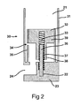
- the flow control valve 30 is mounted in a well 21 at the base of the water tank 20, and comprises a housing 31 and a piston 32 having a head 39 and a shaft 38.
- the piston 32 is resiliently urged upwards by a spring 33 and which, depending upon its vertical position, can block or uncover an aperture 34 in an internal wall 35 of the housing 31.
- the spring 33 is supported on, centred and located by a pin 36 which extends into a bore 37 formed centrally through the shaft 38 and extending up into the head 39 of the piston 32, and which is set in a bore 22 formed in the base 23 of the well 21 of the tank 20.
- This embodiment of the invention addresses that problem since, in operation, pressure from the head of water in the tank 20, combined with suction from the heater 40, causes the piston 32 to move downwards, against the force exerted by the spring 33, thus closing the aperture 34 and temporarily preventing further flow of water out of the outlet 24, since the closure of aperture 34 means that there is no communication between the interior 25 of the water tank 20 and the outlet 24.
- the check valve 72 shuts off, thus removing the suction from the base of the tank 20 and allowing the piston 32 to rise under the influence of spring 33 to uncover the aperture 34, thereby re-establishing communication between the interior 25 of the tank 20 and the tank's outlet 24.
- the check valve 72 re-opens, permitting the suction again to combine with the weight of the head of water to overcome the force exerted by spring 33 and moving the piston 32 downwards again to shut off the aperture 34.
Landscapes
- Engineering & Computer Science (AREA)
- Food Science & Technology (AREA)
- General Engineering & Computer Science (AREA)
- Mechanical Engineering (AREA)
- Apparatus For Making Beverages (AREA)
Abstract
A coffee maker (10) comprises a water tank (20) a heater device (40), a brewing station (50) and a jug or carafe (60) positioned to receive coffee brewed at the station (50). The water tank (20) and the brewing station (50) are interconnected by a water pipe (70), part of which is heated by the heater device (40). The tank (20) is fitted with a flow control valve (30) containing a piston (32) arranged to respond to the head of water in the tank (20) and to heater-induced suction in the pipe (70) by moving within a housing (31) to block or to allow the passage of water from the tank (20) into the pipe (70), thereby to control the flow of water from the tank (20) through the heater (40) to the brewing station (50) so as to ensure that, however much water the tank (20) contains, the heater (40) is able to transfer sufficient heat to water delivered to the brewing station (50) by way of the pipe (70) to provide brewed coffee at a palatable temperature.
Description
- This invention relates to coffee makers and it relates more particularly to valve arrangements for controlling a flow of water from a supply tank through a heater to a coffee-brewing station of a coffee maker.
- Difficulties are experienced with some such coffee makers in that, particularly when the water tank is full and there is a substantial head of standing water, the water tends to flow into and through the heater too rapidly to be sufficiently heated.
- It is an object of the invention to address this difficulty and accordingly there is provided, in or for a coffee maker having a water tank, a heater and a brewing station, a valve arrangement including a flow control valve located in the flow path for water from the tank to the heater; the flow control valve comprising piston means movable between a first position in which said flow path is open, and a second position in which said flow path is closed, and resilient means urging the piston means toward said first position; the arrangement being such that the piston means responds to a head of water corresponding to a substantially full tank and to heater-induced suction to move, against the resilient urge, into said second position, thereby to temporarily close the flow path and thus restrict the flow of water from the tank when the tank is substantially full, but to move back to said first position when the heater-induced suction is relieved, thereby to re-open the flow path; the movements of the piston means thereby regulating the flow of water through the heater, to ensure that water reaching said brewing station is adequately heated irrespective of the amount of water in the tank. The invention also encompasses a coffee maker incorporating such a valve arrangement.
- Preferably, the piston means cycles repeatedly between said first and second positions whilst the tank remains substantially full during the early stages of a brewing operation, and a further preferred arrangement is such that, as the tank empties and the head of water therein reduces, the piston means dwells for longer periods, and eventually remains consistently, in said first position, thereby accommodating a reduced water flow associated with the reduced amount of water in the tank.
- In a preferred embodiment of the invention, the valve arrangement includes a flow control valve mounted in a well at the base of the water tank.
- Another preferred embodiment of the invention further comprises a check valve configured to block a flow of water into the heater as the water is heated, thereby interrupting the heater-induced suction and allowing said resilient urge to return the piston means to the first position to re-open the flow path; and it is further preferred that the check valve is configured to re-open once the heated water has been delivered to the brewing station, thus re-establishing heater-induced suction.
- In order that the invention may be clearly understood and readily carried into effect, one embodiment thereof will now be described, by way of example only, with reference to the accompanying drawings, of which:
- Figure 1 shows, in schematic side elevation and part cross-sectional view, a coffee maker containing a valve arrangement in accordance with one example of the invention; and
- Figure 2 shows, on an enlarged scale and in cross-sectional side view, the valve arrangement of Figure 1.
- Referring now to the drawings, Figure 1 shows, schematically, a
coffee maker 10 comprising awater tank 20 fitted with aflow control valve 30, aheater device 40, abrewing station 50 and a jug orcarafe 60 positioned to receive coffee brewed at thestation 50. Thewater tank 20 and thebrewing station 50 are interconnected, in known manner, by awater pipe 70, part of which is heated by theheater device 40. Thepipe 70 incorporates a check-valve 72, which performs a significant function in relation to the operation of this embodiment of the invention, as will be described later. - Coffee makers are well known products, and those skilled in the art will be aware that the various components described thus far may take many different forms and be provided in many different configurations. For example, it is well known that the
heater device 40 may comprise an electrically-drivenelement 41 of any convenient form, though conveniently it comprises a spirally wound heating element closely coupled to thepipe 70 to promote excellent thermal contact between theheater device 40 and thepipe 70. It is also known that theheater device 70 may heat a pedestal (not shown) upon which the jug orcarafe 60 can sit beneath thebrewing station 50, in order to keep the brewed coffee warm. Moreover, the brewing station may or may not incorporate an arrangement for changing the strength (or aroma) of the brew. It is also known to provide a valve arrangement at the outlet of thebrewing station 50 configured to permit brewed coffee to flow out of thestation 50 only when the jug orcarafe 60 is properly positioned to receive it. - It will be appreciated that such features, and others like them, are usable if desired in coffee makers according to the invention, but that neither their inclusion, nor their particular form if included, has any special bearing upon the subject invention or its operation.
- This invention is concerned with controlling the flow of water from the
tank 20 through theheater 40 to thebrewing station 50 in such a way as to ensure that, however much water thetank 20 contains, theheater 40 is able to heat it sufficiently prior to its delivery to thebrewing station 50. - In the embodiment of the invention now to be described, and as shown in more detail in Figure 2, the
flow control valve 30 is mounted in awell 21 at the base of thewater tank 20, and comprises ahousing 31 and apiston 32 having ahead 39 and ashaft 38. Thepiston 32 is resiliently urged upwards by aspring 33 and which, depending upon its vertical position, can block or uncover anaperture 34 in aninternal wall 35 of thehousing 31. Thespring 33 is supported on, centred and located by apin 36 which extends into abore 37 formed centrally through theshaft 38 and extending up into thehead 39 of thepiston 32, and which is set in abore 22 formed in thebase 23 of thewell 21 of thetank 20. - It is well known that, when the
heater device 40 is actuated, the heating action creates suction in thepipe 70, tending to draw water from theoutlet 24 of thewater tank 20; this action being assisted by the weight of the head of water for the time being held in thetank 20. When the tank is full, the combined effects of the suction and the head of water can cause water to be forced past theheater device 40 at such a rapid rate that the water is unable to draw sufficient heat from thedevice 40 and thus arrives at thebrewing station 50 at a temperature which is too low for the taste of some users. - This embodiment of the invention addresses that problem since, in operation, pressure from the head of water in the
tank 20, combined with suction from theheater 40, causes thepiston 32 to move downwards, against the force exerted by thespring 33, thus closing theaperture 34 and temporarily preventing further flow of water out of theoutlet 24, since the closure ofaperture 34 means that there is no communication between theinterior 25 of thewater tank 20 and theoutlet 24. As the water in thepipe 70 is heated, thecheck valve 72 shuts off, thus removing the suction from the base of thetank 20 and allowing thepiston 32 to rise under the influence ofspring 33 to uncover theaperture 34, thereby re-establishing communication between theinterior 25 of thetank 20 and the tank'soutlet 24. - Once the heated water has been delivered to the
brewing station 50, thecheck valve 72 re-opens, permitting the suction again to combine with the weight of the head of water to overcome the force exerted byspring 33 and moving thepiston 32 downwards again to shut off theaperture 34. - These cycles of operation repeat during at least the early stages of the brewing operation, and the oscillations executed by the
piston 32 thus regulate the flow of water to and through theheater 40, to ensure that it is adequately heated. As thetank 20 empties, the head of water (and thus its weight) reduces and the piston tends to remain longer, and eventually remains consistently, at its uppermost position, thus allowing unrestricted flow from the tank outlet for the reduced forces of water flow associated with the reduced amount of water in the tank. - Although the invention has been described herein with reference to a specific embodiment, various modifications will be evident to those skilled in the art, and the scope of protection provided hereby is not intended to be limited to the aforesaid specific embodiment.
Claims (7)
- In or for a coffee maker (10) having a water tank (20), a heater (40) and a brewing station (50), a valve arrangement characterised by a flow control valve (30) located in the flow path for water from the tank (20) to the heater (40); the flow control valve (30) comprising piston means (32) movable between a first position in which said flow path is open, and a second position in which said flow path is closed, and resilient means (33) urging the piston means (32) toward said first position; the arrangement being such that the piston means (32) responds to a head of water corresponding to a substantially full tank and to heater-induced suction to move, against the resilient urge, into said second position, thereby to temporarily close the flow path and thus restrict the flow of water from the tank (20) when the tank is substantially full, but to move back to said first position when the heater-induced suction is relieved, thereby to re-open the flow path; the movements of the piston means (32) thereby regulating the flow of water through the heater (40), to ensure that water reaching said brewing station (50) is adequately heated irrespective of the amount of water in the tank (20).
- A valve arrangement according to claim 1, wherein said piston means (32) cycles repeatedly between said first and second positions whilst the tank (20) remains substantially full during the early stages of a brewing operation.
- A valve arrangement according to claim 2, wherein, as the tank (20) empties and the head of water therein reduces, the piston means (32) dwells for longer periods, and eventually remains consistently, in said first position, thereby accommodating a reduced water flow associated with the reduced amount of water in the tank (20).
- A valve arrangement according to any preceding claim, wherein said flow control valve (30) is mounted in a well (21) at the base of the water tank (20).
- A valve arrangement according to any preceding claim, further comprising a check valve (72) configured to block a flow of water into the heater (40) as the water is heated, thereby interrupting the heater-induced suction and allowing said resilient urge to return the piston means (32) to the first position to re-open the flow path.
- A valve arrangement according to claim 5, wherein the check valve (72) is configured to re-open once the heated water has been delivered to the brewing station (50), thus re-establishing heater-induced suction.
- A coffee maker (10) incorporating a valve arrangement (30) according to any preceding claim.
Applications Claiming Priority (1)
| Application Number | Priority Date | Filing Date | Title |
|---|---|---|---|
| GB0618528A GB2442012A (en) | 2006-09-21 | 2006-09-21 | Valve for coffee maker |
Publications (1)
| Publication Number | Publication Date |
|---|---|
| EP1908378A1 true EP1908378A1 (en) | 2008-04-09 |
Family
ID=37421315
Family Applications (1)
| Application Number | Title | Priority Date | Filing Date |
|---|---|---|---|
| EP07018187A Withdrawn EP1908378A1 (en) | 2006-09-21 | 2007-09-17 | Coffee maker and valve arrangements therefor |
Country Status (3)
| Country | Link |
|---|---|
| US (1) | US20080072767A1 (en) |
| EP (1) | EP1908378A1 (en) |
| GB (1) | GB2442012A (en) |
Cited By (1)
| Publication number | Priority date | Publication date | Assignee | Title |
|---|---|---|---|---|
| CN104783666A (en) * | 2015-04-30 | 2015-07-22 | 深圳安吉尔饮水产业集团有限公司 | Pressure discharge type one-way valve and water dispenser |
Families Citing this family (2)
| Publication number | Priority date | Publication date | Assignee | Title |
|---|---|---|---|---|
| US20080295698A1 (en) * | 2004-06-10 | 2008-12-04 | The Technology Partnership Plc | Drink Machine |
| US10441105B1 (en) * | 2009-09-28 | 2019-10-15 | Leslie William Fogg, IV | Portable drinking vessel and automatic beverage brewing device |
Citations (3)
| Publication number | Priority date | Publication date | Assignee | Title |
|---|---|---|---|---|
| US6164191A (en) * | 1999-06-04 | 2000-12-26 | Pacific Cornetta Inc. | Single serving beverage maker |
| US6360650B1 (en) * | 2000-07-03 | 2002-03-26 | Joseph Mangiapane | Multiple beverage preparation device |
| EP1402802A1 (en) * | 2002-09-27 | 2004-03-31 | Simatelex Manufactory Company Limited | Coffee maker |
Family Cites Families (4)
| Publication number | Priority date | Publication date | Assignee | Title |
|---|---|---|---|---|
| DE19520121A1 (en) * | 1995-06-01 | 1996-12-05 | Braun Ag | Process for the preparation of hot drinks and device for carrying out the process |
| US5623574A (en) * | 1995-09-25 | 1997-04-22 | Bunn-O-Matic Corporation | Heated water apparatus |
| US6405637B1 (en) * | 2000-01-13 | 2002-06-18 | Houseware Technology Group Llc | Fluid delivery system for generating pressure pulses to make beverages |
| US6374725B1 (en) * | 2000-09-11 | 2002-04-23 | Simatelex Manufactory Co., Ltd. | Coffee maker |
-
2006
- 2006-09-21 GB GB0618528A patent/GB2442012A/en not_active Withdrawn
-
2007
- 2007-09-17 EP EP07018187A patent/EP1908378A1/en not_active Withdrawn
- 2007-09-21 US US11/858,919 patent/US20080072767A1/en not_active Abandoned
Patent Citations (3)
| Publication number | Priority date | Publication date | Assignee | Title |
|---|---|---|---|---|
| US6164191A (en) * | 1999-06-04 | 2000-12-26 | Pacific Cornetta Inc. | Single serving beverage maker |
| US6360650B1 (en) * | 2000-07-03 | 2002-03-26 | Joseph Mangiapane | Multiple beverage preparation device |
| EP1402802A1 (en) * | 2002-09-27 | 2004-03-31 | Simatelex Manufactory Company Limited | Coffee maker |
Cited By (2)
| Publication number | Priority date | Publication date | Assignee | Title |
|---|---|---|---|---|
| CN104783666A (en) * | 2015-04-30 | 2015-07-22 | 深圳安吉尔饮水产业集团有限公司 | Pressure discharge type one-way valve and water dispenser |
| CN104783666B (en) * | 2015-04-30 | 2018-03-20 | 深圳安吉尔饮水产业集团有限公司 | A kind of row pressure formula check valve and water dispenser |
Also Published As
| Publication number | Publication date |
|---|---|
| GB0618528D0 (en) | 2006-11-01 |
| GB2442012A (en) | 2008-03-26 |
| US20080072767A1 (en) | 2008-03-27 |
Similar Documents
| Publication | Publication Date | Title |
|---|---|---|
| US8011290B2 (en) | Apparatus for preparing a beverage suitable for consumption, such as coffee | |
| US9596957B2 (en) | Relief and safety valve for instant beverage machines | |
| EP2959808B1 (en) | Improved device for wetting a dose of ground coffee in coffee machines having a heating element on the dispenser unit, and wetting process | |
| US20090229471A1 (en) | Two Cups Automatic Coffee Maker with Flow Control | |
| CN206381074U (en) | Individual accumulator beverage preparation machine | |
| US20150282662A1 (en) | Stop valve for coffee maker | |
| KR102161259B1 (en) | Beverage supply device | |
| US20210330118A1 (en) | Beverage Maker | |
| CN101400286A (en) | Method and apparatus for producing beverages | |
| CN107105932B (en) | Apparatus and method for preparing a beverage | |
| EP1908378A1 (en) | Coffee maker and valve arrangements therefor | |
| US7032502B2 (en) | Coffee maker | |
| EP4418963B1 (en) | Coffee machine for preparing coffee with highly flexible use | |
| CN100566639C (en) | Apparatus for preparing beverages | |
| EP1938719B1 (en) | Two-in-one beverage mechanism | |
| US10555637B2 (en) | Brewer with temperature responsive control valve | |
| CN115778184A (en) | Water vapor isolation method of coffee machine | |
| KR100619157B1 (en) | Green tea maker | |
| CN109068887B (en) | Brewing unit and beverage making device comprising such a brewing unit | |
| US20150359375A1 (en) | Pressurized Beverage Maker | |
| KR20250056129A (en) | Apparatus for Making Drip Coffee | |
| KR101297554B1 (en) | Apparatus For Extracting Coffee | |
| JP2022093595A (en) | Electric coffee maker |
Legal Events
| Date | Code | Title | Description |
|---|---|---|---|
| PUAI | Public reference made under article 153(3) epc to a published international application that has entered the european phase |
Free format text: ORIGINAL CODE: 0009012 |
|
| 17P | Request for examination filed |
Effective date: 20070926 |
|
| AK | Designated contracting states |
Kind code of ref document: A1 Designated state(s): AT BE BG CH CY CZ DE DK EE ES FI FR GB GR HU IE IS IT LI LT LU LV MC MT NL PL PT RO SE SI SK TR |
|
| AX | Request for extension of the european patent |
Extension state: AL BA HR MK RS |
|
| STAA | Information on the status of an ep patent application or granted ep patent |
Free format text: STATUS: THE APPLICATION HAS BEEN WITHDRAWN |
|
| 18W | Application withdrawn |
Effective date: 20080419 |