EP1908353B1 - Fish distributing table - Google Patents
Fish distributing table Download PDFInfo
- Publication number
- EP1908353B1 EP1908353B1 EP07122282A EP07122282A EP1908353B1 EP 1908353 B1 EP1908353 B1 EP 1908353B1 EP 07122282 A EP07122282 A EP 07122282A EP 07122282 A EP07122282 A EP 07122282A EP 1908353 B1 EP1908353 B1 EP 1908353B1
- Authority
- EP
- European Patent Office
- Prior art keywords
- fish
- weir
- stunning
- reservoir
- piston
- Prior art date
- Legal status (The legal status is an assumption and is not a legal conclusion. Google has not performed a legal analysis and makes no representation as to the accuracy of the status listed.)
- Expired - Lifetime
Links
- 241000251468 Actinopterygii Species 0.000 claims abstract description 107
- XLYOFNOQVPJJNP-UHFFFAOYSA-N water Substances O XLYOFNOQVPJJNP-UHFFFAOYSA-N 0.000 claims description 27
- 238000010586 diagram Methods 0.000 description 7
- 238000000034 method Methods 0.000 description 3
- 239000012530 fluid Substances 0.000 description 2
- JVTAAEKCZFNVCJ-UHFFFAOYSA-N lactic acid Chemical compound CC(O)C(O)=O JVTAAEKCZFNVCJ-UHFFFAOYSA-N 0.000 description 2
- 239000004809 Teflon Substances 0.000 description 1
- 229920006362 Teflon® Polymers 0.000 description 1
- 230000004913 activation Effects 0.000 description 1
- 230000000740 bleeding effect Effects 0.000 description 1
- 230000000994 depressogenic effect Effects 0.000 description 1
- 235000014655 lactic acid Nutrition 0.000 description 1
- 239000004310 lactic acid Substances 0.000 description 1
- 239000004033 plastic Substances 0.000 description 1
- 229920003023 plastic Polymers 0.000 description 1
- 238000005086 pumping Methods 0.000 description 1
Images


Classifications
-
- A—HUMAN NECESSITIES
- A22—BUTCHERING; MEAT TREATMENT; PROCESSING POULTRY OR FISH
- A22B—SLAUGHTERING
- A22B3/00—Slaughtering or stunning
- A22B3/08—Slaughtering or stunning for poultry or fish, e.g. slaughtering pliers, slaughtering shears
- A22B3/083—Stunning devices specially adapted for fish
-
- A—HUMAN NECESSITIES
- A01—AGRICULTURE; FORESTRY; ANIMAL HUSBANDRY; HUNTING; TRAPPING; FISHING
- A01K—ANIMAL HUSBANDRY; AVICULTURE; APICULTURE; PISCICULTURE; FISHING; REARING OR BREEDING ANIMALS, NOT OTHERWISE PROVIDED FOR; NEW BREEDS OF ANIMALS
- A01K61/00—Culture of aquatic animals
- A01K61/90—Sorting, grading, counting or marking live aquatic animals, e.g. sex determination
- A01K61/95—Sorting, grading, counting or marking live aquatic animals, e.g. sex determination specially adapted for fish
-
- A—HUMAN NECESSITIES
- A22—BUTCHERING; MEAT TREATMENT; PROCESSING POULTRY OR FISH
- A22B—SLAUGHTERING
- A22B3/00—Slaughtering or stunning
- A22B3/02—Slaughtering or stunning by means of bolts, e.g. slaughtering pistols, cartridges
Definitions
- This invention relates to a table for distributing fish for stunning.
- a problem with this process is that often the fish are pumped onto the table in waves. A large number of fish are often located on the table at one time creating a backlog of fish. An operator that uses the fish stunning apparatus shown in WO 01/97621 must push the fish forwardly through the guide in order to stun the fish. The difficulty arises when the fish must be removed as the backlog often hinders or sometimes prevents the removal of the fish. Further, as there is a passageway that must be provided to allow fish to be passed further along the table, fish that have not been stunned can be passed through this passageway which is undesirable,
- WO 99/46997 discloses an apparatus and method for stunning and killing fish, but the apparatus does not include a water flow device to add water to a reservoir wherein the device is orientated to add water in a direction from a weir in the device.
- a table for distributing fish for stunning comprising:
- FIGS. 1 , 2A and 2B show a fish stunning apparatus 10 including a fish stunning device 100, a fish guide 200 and a trigger 300.
- the fish stunning device 100 is mounted to the top of the fish guide 200.
- the fish stunning device 100 includes a striker 400, a control box 110, a regulator 120 and an oiler 130 that are all mounted to a mount 140.
- the fish guide 200 includes a pair of side walls 210 and a pivotally mountable floor 220.
- a front of the side wall defines an entrance 230 into which fish are passed and a back of the guide defines an exit 240 from which the fish are passed.
- the fish stunning device 100 is mounted to the top of the fish guide using the mount 140 and pins 250 that are located on the side walls of the fish guide.
- the fish guide 200 include slots 141 that are able to be used to adjust the height of the striker 400 relative to the floor 220.
- the floor 200 is pivotally movable between a first position where the fish is located through the entrance 230 within the guide to be stunned and a second position where the fish is passed from the guide through the exit of the guide 240.
- the floor 220 is moved between the first and second position using a pair of pneumatic rams 260 connected to the underside of the floor 220.
- the trigger 300 is mounted adjacent the striker 400.
- the trigger 300 is operatively connected to striker 400 and the floor 220.
- a pin pneumatic ram 310 is connected to the trigger 300 to ensure that the trigger is fully engaged when activated.
- the striker 400 shown in more detail in FIGS. 3A to 3D , is formed from a head 420, a main body 440 and a foot 460.
- a pneumatic ram 441 is located within the main body 440 that includes a cylinder 442 and a piston 443 that is reciprocatable within the cylinder 442.
- the piston 443 is made from a single piece of plastics that is easily removable and difficult to break.
- An O-ring 445 provides a seal between the cylinder 442 and the piston 443.
- the piston 442 is movable between an extension position and retraction position.
- the main body 440 also includes a low-pressure chamber 446 that is linked to a low-pressure inlet port 447 and a high-pressure chamber 449 that is linked to a high-pressure inlet port 448.
- the cylinder 442 is in fluid communication with the low-pressure chamber via a ring of holes 450 located at the bottom of the cylinder 442. Two additional holes 451 located at the bottom of the cylinder 442 are also in fluid communication with the low-pressure chamber 446.
- the high-pressure chamber 449 extends into the head 420 of the striker 400 via an aperture 452 in the main body 440.
- the head 420 includes a control chamber 421 that is linked to a control port 422.
- a control piston valve 423 is reciprocately mounted within the head 420 and movable between a striker position and a non-striker position. The pressure located within the control chamber 421 controls the movement at the control piston valve 423 between the striker and non-striker positions.
- An outlet port 424 is located above the control piston valve 423 and allows air to pass from the head 420.
- a passageway 425 extends through control piston valve 423 to allow air to pass from the cylinder out the outlet port 424.
- a seal 426 is located above the passageway 425 to seal the passageway 425 when the control piston valve 423 is in the striker position.
- the foot 460 has an aperture 461 through which the piston 443 extends when in the extended position.
- a Teflon, self-lubricating washer 462 is located within the foot to allow smooth reciprocation of the piston.
- the striker operates in the following manner.
- the piston 443 starts in the retracted position with the control piston valve 423 in the non-striker position as shown in FIG. 3A .
- the control piston valve 423 is held in the non-striker position by high-pressure air that is fed through the control port 422.
- the control port 422 is opened to allow pressure to be released from the control chamber 421 as shown in FIG. 3B . This allows the control piston valve 423 to move into the striker position where the passageway 425 is sealed against the seal 426. High-pressure passes from the high-pressure chamber 449 into the cylinder 442 to cause the piston 443 to be moved to the extended position as shown in FIG. 3C . Air located within the cylinder 442 is passed out of the inlet port 447 when the piston 443 travels down the cylinder 442.
- the air is feed in the low-pressure chamber 446 through low-pressure inlet port 447 and passes through the ring of holes 450 located within the cylinder 442 to cause the piston 443 to be retracted within the cylinder 442.
- Air located within the cylinder 442 passes through the control piston valve 423 and through the outlet 424 to complete operation of the striker.
- the regulator 120 supplies air to the ports 422, 448 of the striker using standard fittings such as those sold by FESTO.
- a smaller regulator 290 supplies low-pressure air through the port 447.
- a pressure gauge 121 indicates that adequate pressure is being supplied through the regulator 120.
- FIGS. 5A to 5D show a pneumatic circuit diagram showing the operation of the pneumatic rams 260 that control the operation of the floor 220. It should be appreciated that in this embodiment that the operation of the striker and the floor 220 are timed so that the floor will drop after the piston 443 has reached its extended position.
- the pneumatic circuit diagram shown is formed from a trigger valve 301, floor ram valve 270, timer valve 280 and regulator 290.
- FIG. 5A shows the pneumatic circuit diagram prior to activation of the trigger 300.
- Air is also supplied to the pin pneumatic ram 310 to cause the ram to be extended.
- the pin pneumatic ram 310 is provided such that the trigger becomes fully retracted whenever the floor ram valve 270 is switched to lower the floor 220. In some instance, the trigger may not be fully engaged immediately. This will normally occur when a fish only lightly taps the trigger 300. This will allow sufficient air to pass from the control chamber 421 through the control port 422 to switch the position of floor ram valve 270 but will not allow the piston 443 to be extended.
- the pin pneumatic ram 310 the piston 443 will always be moved to the extended position when the floor 220 is lowered.
- the trigger is moved back to its original position after a fish activates the trigger as shown in FIG. 5C . This causes air to pass from the pneumatic ram through the exhaust valve.
- FIGS. 4A to 4D shows the operating of the fish stunning apparatus 100.
- the fish stunning apparatus 100 operates by a fish being placed through the entrance 230 of the guide 200. Once the fish is placed within the entrance 230, the trigger 300 is depressed and the striker 400 is activated.
- the floor 220 is then moved back to its original position to allow for another fish to pass through the entrance 220 into the guide 200.
- FIG. 6 shows a table 500 for distributing fish for stunning.
- the table 500 includes a reservoir 510, an inlet 520, a weir 530, a slide 540, a drain 550 and a series of nozzles 560 that are directed outwardly from the weir 530.
- the reservoir 510 is formed from a pair of opposing side walls 511, an end wall 512, a base 513 and the weir 530.
- the reservoir 510 holds water and fish until they are ready for distribution through the stunning apparatus 10 as shown in FIG. 7A .
- the inlet 520 located in the base of the reservoir 510, is used to pump fish and water into the reservoir 510.
- the weir 530 is at the front of the reservoir 510 and is used to allow fish to be passed from the reservoir 510.
- the nozzles 560 are located along a face of the weir 560 and water is pumped through these nozzles 560 into the reservoir 510.
- a slide 540 extends from the front of the weir 530 to cause the fish to slide towards the fish stunning apparatus after they pass over the weir 510.
- Chutes 580 ensure the fish are fed directly into the fish stunning apparatus 10.
- the drain 550 is located at the lower end of the slide 540 and to drain any water that passes over the weir 530.
- a further drain 550 is located adjacent the end wall 512 of the reservoir 510.
- a grate 571 extends the length of the end wall to allow water to pass from the reservoir into the drain 570.
- the table operates by pumping fish and water through the inlet 520 into the reservoir 510. Water is passed through the nozzles 560 to create an artificial current that extends away from the weir 530 towards the grate 571 in the end wall 512. The fish located within the reservoir 510 swim toward the current as is their natural tendency. Hence, the fish become aligned so that their head faces toward the weir 530.
- Increasing the flow of water through the nozzles 560 and/or inlet then increases the level of the water located within the reservoir 510 above the weir 530 as shown in FIG. 7B . Water and fish are thus allowed to pass from the reservoir 510 over the weir 530. The water flows through the chutes 580 and the fish continue to slide down the slide 540 through fish stunning apparatus 100.
- the fish flow over the weir 530 headfirst as they are facing the weir 530 prior to the level of water in the reservoir 510 being increased. As the fish travel head first over the weir 530 and down the slide, fish can be fed through the fish stunning machine automatically without the need to be fed manually.
- the fish stunning apparatus 10 and table 500 provide the advantage of quick and efficient stunning of fish with minimal operator input and minimal stoppages.
Landscapes
- Life Sciences & Earth Sciences (AREA)
- Engineering & Computer Science (AREA)
- Food Science & Technology (AREA)
- Zoology (AREA)
- Environmental Sciences (AREA)
- Biodiversity & Conservation Biology (AREA)
- Animal Husbandry (AREA)
- Marine Sciences & Fisheries (AREA)
- Processing Of Meat And Fish (AREA)
- Medicines Containing Material From Animals Or Micro-Organisms (AREA)
- Magnetic Resonance Imaging Apparatus (AREA)
- Farming Of Fish And Shellfish (AREA)
- Mechanical Means For Catching Fish (AREA)
Abstract
Description
- This invention relates to a table for distributing fish for stunning.
- It has been found that by stunning fish, the quality of the flesh of the fish is increased as death does not induce the creation of lactic acid in the flesh of the fish. Fish are stunned in a number of ways including the most basic method of hitting the fish with a bat to using more complex devices in which the fish are stunned using a pneumatically driven ram.
- In most commercial operated fisheries more complex pneumatic rams are used as they are more efficient and less physically demanding on an operator. An example of a fish stunning device that uses a pneumatic ram is disclosed in
International Patent Application No. WO 01/97621 - When fish are harvested, they are located in a holding area and then pumped onto a table. The fish are grabbed by an operator and stunned usually using a pneumatically driven stunning device that is mounted to the table. A guide is used to guide the head of the fish into the stunning device to activate a trigger to cause the pneumatic ram to be extended and stun the fish. The fish is then withdrawn from the guide and passed further along the table for other operations such as bleeding.
- A problem with this process is that often the fish are pumped onto the table in waves. A large number of fish are often located on the table at one time creating a backlog of fish. An operator that uses the fish stunning apparatus shown in
WO 01/97621 -
WO 99/46997 - It is an object of the invention to overcome or alleviate the above disadvantages or provide the consumer with a useful or commercial choice.
- A table for distributing fish for stunning; said table comprising:
- a reservoir for holding fish and water;
- an inlet to introduce fish into the reservoir
- a weir to allow fish to pass from said reservoir;
- a slide to distribute fish after they pass from the weir,
- Embodiments, by way of example only, will be described with reference to the accompanying drawings in which:
-
FIG. 1 is a perspective view of a fish stunning apparatus; -
FIG. 2A is a side view of the fish stunning apparatus according toFIG. 1 ; -
FIG. 2B is a partial side sectional side view of the fish stunning apparatus according toFIG. 1 ; -
FIG. 3A is a side sectional view of a striker in a first position; -
FIG. 3B is a side sectional view of the striker in a second position; -
FIG. 3C is a side sectional view of the striker in a third position; -
FIG. 3D is a side sectional view of the striker in a fourth position; -
FIG. 4A is a side sectional view of the fish stunning apparatus in a first position; -
FIG. 4B is a side sectional view of the fish stunning apparatus in a second position; -
FIG. 4C is a side sectional view of the fish stunning apparatus in a third position; -
FIG. 4D is a side sectional view of the fish stunning apparatus in a fourth position; -
FIG. 5A is a schematic drawing of the pneumatic circuit diagram used to operate a floor of a fish guide; -
FIG. 5B is a further schematic drawing of the pneumatic circuit diagram used to operate a floor of a fish guide; -
FIG. 5C is another further schematic drawing of the pneumatic circuit diagram used to operate a floor of a fish guide; -
FIG. 5D is yet another further schematic drawing of the pneumatic circuit diagram used to operate a floor of a fish guide; -
Figures 1-5D do not form part of the present invention -
FIG. 6 is a perspective view of a table for distributing fish according to an embodiment of the invention; -
FIG. 7A is a side sectional view of the table ofFIG. 6 ; and -
FIG. 7B is a further side sectional view of the table ofFIG. 6 . -
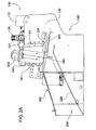
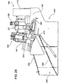
FIGS. 1 ,2A and2B show a fishstunning apparatus 10 including a fishstunning device 100, afish guide 200 and atrigger 300. - The fish
stunning device 100 is mounted to the top of thefish guide 200. The fishstunning device 100 includes astriker 400, acontrol box 110, aregulator 120 and anoiler 130 that are all mounted to amount 140. - The
fish guide 200 includes a pair ofside walls 210 and a pivotallymountable floor 220. A front of the side wall defines anentrance 230 into which fish are passed and a back of the guide defines anexit 240 from which the fish are passed. - The fish
stunning device 100 is mounted to the top of the fish guide using themount 140 and pins 250 that are located on the side walls of the fish guide. Thefish guide 200 includeslots 141 that are able to be used to adjust the height of thestriker 400 relative to thefloor 220. - The
floor 200 is pivotally movable between a first position where the fish is located through theentrance 230 within the guide to be stunned and a second position where the fish is passed from the guide through the exit of theguide 240. - The
floor 220 is moved between the first and second position using a pair ofpneumatic rams 260 connected to the underside of thefloor 220. - The
trigger 300 is mounted adjacent thestriker 400. Thetrigger 300 is operatively connected tostriker 400 and thefloor 220. A pinpneumatic ram 310 is connected to thetrigger 300 to ensure that the trigger is fully engaged when activated. - The
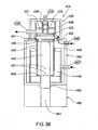
striker 400, shown in more detail inFIGS. 3A to 3D , is formed from ahead 420, amain body 440 and afoot 460. - A
pneumatic ram 441 is located within themain body 440 that includes acylinder 442 and apiston 443 that is reciprocatable within thecylinder 442. Thepiston 443 is made from a single piece of plastics that is easily removable and difficult to break. An O-ring 445 provides a seal between thecylinder 442 and thepiston 443. Thepiston 442 is movable between an extension position and retraction position. - The
main body 440 also includes a low-pressure chamber 446 that is linked to a low-pressure inlet port 447 and a high-pressure chamber 449 that is linked to a high-pressure inlet port 448. - The
cylinder 442 is in fluid communication with the low-pressure chamber via a ring ofholes 450 located at the bottom of thecylinder 442. Twoadditional holes 451 located at the bottom of thecylinder 442 are also in fluid communication with the low-pressure chamber 446. - The high-
pressure chamber 449 extends into thehead 420 of thestriker 400 via anaperture 452 in themain body 440. - The
head 420 includes acontrol chamber 421 that is linked to acontrol port 422. Acontrol piston valve 423 is reciprocately mounted within thehead 420 and movable between a striker position and a non-striker position. The pressure located within thecontrol chamber 421 controls the movement at thecontrol piston valve 423 between the striker and non-striker positions. - An
outlet port 424 is located above thecontrol piston valve 423 and allows air to pass from thehead 420. Apassageway 425 extends throughcontrol piston valve 423 to allow air to pass from the cylinder out theoutlet port 424. Aseal 426 is located above thepassageway 425 to seal thepassageway 425 when thecontrol piston valve 423 is in the striker position. - The
foot 460 has anaperture 461 through which thepiston 443 extends when in the extended position. A Teflon, self-lubricatingwasher 462 is located within the foot to allow smooth reciprocation of the piston. - The striker operates in the following manner. The
piston 443 starts in the retracted position with thecontrol piston valve 423 in the non-striker position as shown inFIG. 3A . Thecontrol piston valve 423 is held in the non-striker position by high-pressure air that is fed through thecontrol port 422. - The
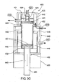
control port 422 is opened to allow pressure to be released from thecontrol chamber 421 as shown inFIG. 3B . This allows thecontrol piston valve 423 to move into the striker position where thepassageway 425 is sealed against theseal 426. High-pressure passes from the high-pressure chamber 449 into thecylinder 442 to cause thepiston 443 to be moved to the extended position as shown inFIG. 3C . Air located within thecylinder 442 is passed out of theinlet port 447 when thepiston 443 travels down thecylinder 442. - When the
piston 443 is close to the bottom of thecylinder 442, air is passed through twoholes 451 located within thecylinder 442. This causes high-pressure air to be passed from within thecylinder 442 into the low-pressure chamber 446. - When the
piston 443 reaches the bottom of thecylinder 442, high-pressure air is passed through thecontrol port 422 into thecontrol chamber 421 to move thecontrol piston valve 423 to the non-striker position as shown inFiG. 3D . - The air is feed in the low-
pressure chamber 446 through low-pressure inlet port 447 and passes through the ring ofholes 450 located within thecylinder 442 to cause thepiston 443 to be retracted within thecylinder 442. Air located within thecylinder 442 passes through thecontrol piston valve 423 and through theoutlet 424 to complete operation of the striker. - The
regulator 120 supplies air to theports smaller regulator 290 supplies low-pressure air through theport 447. Apressure gauge 121 indicates that adequate pressure is being supplied through theregulator 120. -
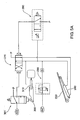
FIGS. 5A to 5D show a pneumatic circuit diagram showing the operation of thepneumatic rams 260 that control the operation of thefloor 220. It should be appreciated that in this embodiment that the operation of the striker and thefloor 220 are timed so that the floor will drop after thepiston 443 has reached its extended position. - The pneumatic circuit diagram shown is formed from a
trigger valve 301,floor ram valve 270,timer valve 280 andregulator 290.FIG. 5A shows the pneumatic circuit diagram prior to activation of thetrigger 300. - Once the
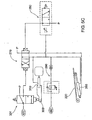
trigger valve 301 is activated via thetrigger valve 300, as shown inFIG. 5B , air expelled from thecontrol chamber 421 through thecontrol port 422 is passed through thetrigger valve 301 to switch the position ofram valve 270. Air is then supplied to thepneumatic rams 260 to cause thepneumatic rams 260 to lower thefloor 220. At the same time, air is used to switch ontimer valve 280. - Air is also supplied to the pin
pneumatic ram 310 to cause the ram to be extended. The pinpneumatic ram 310 is provided such that the trigger becomes fully retracted whenever thefloor ram valve 270 is switched to lower thefloor 220. In some instance, the trigger may not be fully engaged immediately. This will normally occur when a fish only lightly taps thetrigger 300. This will allow sufficient air to pass from thecontrol chamber 421 through thecontrol port 422 to switch the position offloor ram valve 270 but will not allow thepiston 443 to be extended. By providing the pinpneumatic ram 310, thepiston 443 will always be moved to the extended position when thefloor 220 is lowered. - The trigger is moved back to its original position after a fish activates the trigger as shown in
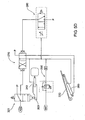
FIG. 5C . This causes air to pass from the pneumatic ram through the exhaust valve. - After a predetermined time, air is supplied through the
timer valve 280 to switch thefloor ram valve 220 to supply air to thepneumatic rams 260 to raise thefloor 220 as shown inFIG. 5D . -
FIGS. 4A to 4D shows the operating of the fishstunning apparatus 100. - The fish
stunning apparatus 100 operates by a fish being placed through theentrance 230 of theguide 200. Once the fish is placed within theentrance 230, thetrigger 300 is depressed and thestriker 400 is activated. - The
piston 443, located within thecylinder 442, moves to the extended position hitting the fish on the head, stunning the fish. After the fish has been stunned, thefloor 220 moves downwardly causing the fish to pass through theexit 240 at the back of theguide 200. There is a slight delay between thepiston 443 being fully extended and thefloor 220 pivoting downwardly to ensure that thepiston 443 stuns the fish. - The
floor 220 is then moved back to its original position to allow for another fish to pass through theentrance 220 into theguide 200. -
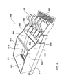
FIG. 6 shows a table 500 for distributing fish for stunning. The table 500 includes areservoir 510, aninlet 520, aweir 530, aslide 540, adrain 550 and a series ofnozzles 560 that are directed outwardly from theweir 530. - The
reservoir 510 is formed from a pair of opposingside walls 511, anend wall 512, abase 513 and theweir 530. Thereservoir 510 holds water and fish until they are ready for distribution through thestunning apparatus 10 as shown inFIG. 7A . - The
inlet 520, located in the base of thereservoir 510, is used to pump fish and water into thereservoir 510. - The
weir 530 is at the front of thereservoir 510 and is used to allow fish to be passed from thereservoir 510. Thenozzles 560 are located along a face of theweir 560 and water is pumped through thesenozzles 560 into thereservoir 510. - A
slide 540 extends from the front of theweir 530 to cause the fish to slide towards the fish stunning apparatus after they pass over theweir 510.Chutes 580 ensure the fish are fed directly into the fishstunning apparatus 10. Thedrain 550 is located at the lower end of theslide 540 and to drain any water that passes over theweir 530. - A
further drain 550 is located adjacent theend wall 512 of thereservoir 510. Agrate 571 extends the length of the end wall to allow water to pass from the reservoir into thedrain 570. - The table operates by pumping fish and water through the
inlet 520 into thereservoir 510. Water is passed through thenozzles 560 to create an artificial current that extends away from theweir 530 towards thegrate 571 in theend wall 512. The fish located within thereservoir 510 swim toward the current as is their natural tendency. Hence, the fish become aligned so that their head faces toward theweir 530. - Increasing the flow of water through the
nozzles 560 and/or inlet then increases the level of the water located within thereservoir 510 above theweir 530 as shown inFIG. 7B . Water and fish are thus allowed to pass from thereservoir 510 over theweir 530. The water flows through thechutes 580 and the fish continue to slide down theslide 540 through fishstunning apparatus 100. - The fish flow over the
weir 530 headfirst as they are facing theweir 530 prior to the level of water in thereservoir 510 being increased. As the fish travel head first over theweir 530 and down the slide, fish can be fed through the fish stunning machine automatically without the need to be fed manually. - The fish
stunning apparatus 10 and table 500 provide the advantage of quick and efficient stunning of fish with minimal operator input and minimal stoppages.
Claims (8)
- A table (500) for distributing fish for stunning; said table (500) comprising:a reservoir (510) for holding fish and water;an inlet (520) to introduce fish into the reservoir (510);a weir (530) to allow fish to pass from said reservoir;a slide (540) to distribute fish after they pass from the weir (530),characterised in that the table (500) comprises a water flow device to add water to the reservoir (510), wherein the water flow device is orientated to add water in a direction away from the weir (530).
- The table (500) of claim 1 wherein the water flow device is a series of nozzles (560) that are directed outwardly from the weir (530).
- The table (5 00) of claim 2 wherein the nozzles (560) are located along a face of the weir (530).
- The table (500) of claim 1 including at least one fish stunning apparatus (100).
- The table (500) of claim 4 wherein the fish stunning apparatus (100) is located on the slide (540).
- The table (500) of claim 5 wherein at least one chute is provided on the slide (540) to direct fish into the stunning apparatus (100).
- The table (500) of claim 1 further including a drain (550) to drain water that passes over the weir (530) from the reservoir (510).
- The table (500) of claim 7 wherein the drain (550) is located on the slide (540) at a point lower than that of the fish stunning apparatus (100).
Applications Claiming Priority (2)
| Application Number | Priority Date | Filing Date | Title |
|---|---|---|---|
| AU2002953070A AU2002953070A0 (en) | 2002-12-03 | 2002-12-03 | A fish stunning apparatus |
| EP03812105A EP1581060B1 (en) | 2002-12-03 | 2003-12-03 | A fish stunning apparatus |
Related Parent Applications (2)
| Application Number | Title | Priority Date | Filing Date |
|---|---|---|---|
| EP03812105.9 Division | 2003-12-03 | ||
| EP03812105A Division EP1581060B1 (en) | 2002-12-03 | 2003-12-03 | A fish stunning apparatus |
Publications (2)
| Publication Number | Publication Date |
|---|---|
| EP1908353A1 EP1908353A1 (en) | 2008-04-09 |
| EP1908353B1 true EP1908353B1 (en) | 2010-03-17 |
Family
ID=29408794
Family Applications (2)
| Application Number | Title | Priority Date | Filing Date |
|---|---|---|---|
| EP03812105A Expired - Lifetime EP1581060B1 (en) | 2002-12-03 | 2003-12-03 | A fish stunning apparatus |
| EP07122282A Expired - Lifetime EP1908353B1 (en) | 2002-12-03 | 2003-12-03 | Fish distributing table |
Family Applications Before (1)
| Application Number | Title | Priority Date | Filing Date |
|---|---|---|---|
| EP03812105A Expired - Lifetime EP1581060B1 (en) | 2002-12-03 | 2003-12-03 | A fish stunning apparatus |
Country Status (9)
| Country | Link |
|---|---|
| US (2) | US7220177B2 (en) |
| EP (2) | EP1581060B1 (en) |
| AT (1) | ATE422295T1 (en) |
| AU (2) | AU2002953070A0 (en) |
| CA (2) | CA2507730C (en) |
| DE (1) | DE60326174D1 (en) |
| NO (2) | NO337212B1 (en) |
| NZ (2) | NZ541044A (en) |
| WO (1) | WO2004049810A1 (en) |
Cited By (2)
| Publication number | Priority date | Publication date | Assignee | Title |
|---|---|---|---|---|
| CN105142410A (en) * | 2013-02-20 | 2015-12-09 | 北欧机械制造鲁道夫巴德尔有限及两合公司 | fish processing equipment |
| WO2022086341A1 (en) | 2020-10-23 | 2022-04-28 | Stranda Prolog As | System for separation and orientation of fish |
Families Citing this family (22)
| Publication number | Priority date | Publication date | Assignee | Title |
|---|---|---|---|---|
| WO2005089558A1 (en) * | 2004-03-22 | 2005-09-29 | Richard Bass | Improved fish stunning device |
| CA2531981A1 (en) * | 2005-01-07 | 2006-07-07 | Fundacion Chile | Salmon harvest equipment that causes cerebral death in fish, improving fillet yield, said equipment having a cylinder-shaped piston that allows the attachment of different types of sharp-pointed punches at its bottom end acting over the head of the fish |
| WO2008009043A1 (en) * | 2006-07-17 | 2008-01-24 | Richard Bass | Separator for fish or similar objects |
| US7980925B2 (en) * | 2007-06-04 | 2011-07-19 | Richard Bass Pty Ltd | Fish processing device |
| DE102007053905B3 (en) * | 2007-11-09 | 2009-01-29 | Nordischer Maschinenbau Rud. Baader Gmbh + Co. Kg | Apparatus for free cutting the flank bones of decapitated, slaughtered and opened in their abdominal cavity fish and filleting machine for filleting beheaded, slaughtered and opened in her abdominal cavity fish with such a device |
| NO20083924A (en) * | 2008-09-15 | 2010-01-18 | Seaside As | Fish processing system |
| WO2011021071A1 (en) * | 2009-08-19 | 2011-02-24 | Tecsur S.A. | Fish-processing apparatus |
| US9021987B1 (en) * | 2009-09-29 | 2015-05-05 | Aquama of Aquaculture Technologies, Ltd | Vertically integrated aquaculture system |
| WO2012020283A1 (en) * | 2010-08-13 | 2012-02-16 | Osvaldo Joaquin Baeza Rischter | Fish processing apparatus |
| US8973565B2 (en) * | 2011-08-09 | 2015-03-10 | The United States Of America As Represented By The Secretary Of The Army | Device and method for inducing brain injury in animal test subjects |
| CL2012000307A1 (en) * | 2012-02-06 | 2012-08-24 | Rischter Osvaldo Joaquin Baeza | Apparatus for slaughtering fish that causes the death of the fish by taking it from the operculum to be positioned in a knockout position and only cutting the gills, it comprises transverse positioning means that receive the fish longitudinal positioning means, gripping means, knocking means. |
| CL2012003064A1 (en) * | 2012-10-31 | 2013-01-18 | Rischter Osvaldo Joaquin Baeza | Device for processing fish by knocking and cutting gills or aorta comprising an input and output assembly containing a fixed lateral guide plate, a mobile lateral guide plate, displacement means and a pneumatic circuit that connects a trigger assembly, a piston assembly knocker and means of displacement. |
| US8821221B1 (en) * | 2013-03-13 | 2014-09-02 | Randall Bock | Captive bolt tool system for use in humane dispatch of livestock |
| EP3182831B1 (en) | 2014-08-22 | 2019-06-26 | Nordischer Maschinenbau Rud. Baader GmbH + Co. KG | Device for stunning fish, trigger unit and method for releasing the striker of the stunning device |
| AU2016414201B2 (en) * | 2016-07-08 | 2019-10-31 | Nordischer Maschinenbau Rud. Baader Gmbh + Co. Kg | Fish slaughter device and trigger device configured for same |
| FR3062987B1 (en) * | 2017-02-23 | 2021-11-05 | Etablissements Faivre | FISH DISTRIBUTION PROCESS AND DEVICE. |
| EP3639670B1 (en) * | 2018-10-19 | 2021-09-22 | Nordischer Maschinenbau Rud. Baader GmbH + Co. KG | Apparatus and method for aligning the abdomen and back of a fish |
| CN109566708A (en) * | 2018-12-10 | 2019-04-05 | 江苏深蓝远洋渔业有限公司 | A kind of full-automatic krill distribution system applied in euphausia superba |
| BR102020015306B1 (en) * | 2020-04-15 | 2022-12-27 | Jarvis Products Corporation | PNEUMATIC ANIMAL STUNNER, METHOD FOR STUNNING AN ANIMAL AND RETENTION PISTON |
| CN111887191B (en) * | 2020-08-19 | 2022-09-20 | 益阳市龙头洲生态农业发展有限公司 | A partial shipment equipment for fry screening |
| NO347169B1 (en) * | 2021-08-23 | 2023-06-19 | Hoseth Holding AS | Apparatus and method for fish stunning |
| WO2025067657A1 (en) * | 2023-09-28 | 2025-04-03 | Nordischer Maschinenbau Rud. Baader Gmbh + Co. Kg | Apparatus and method for automatically stunning fish |
Family Cites Families (27)
| Publication number | Priority date | Publication date | Assignee | Title |
|---|---|---|---|---|
| DE628177C (en) * | 1936-03-31 | Anna Gueldenzoph | Device for killing fish | |
| US1373812A (en) * | 1919-08-14 | 1921-04-05 | Heath Frank | Sardine-turning apparatus |
| US3128744A (en) * | 1963-01-02 | 1964-04-14 | Keith B Jefferts | Method for investigating the migratory habits of macro-organisms |
| US3229326A (en) * | 1963-11-13 | 1966-01-18 | Trio Fab As | Arrangement for feeding of fish |
| US3514811A (en) * | 1968-10-30 | 1970-06-02 | Us Interior | Fish orienter |
| US3783623A (en) * | 1972-02-08 | 1974-01-08 | S Ogden | Fish escalator |
| NZ214348A (en) * | 1985-11-27 | 1988-07-28 | Walker T H & Sons Ltd | Electrically stunning animals through nose and neck contacts |
| NO162941C (en) * | 1987-11-27 | 1990-03-14 | Trio Ind As | FISH VACCINATION MACHINE. |
| DK162564C (en) * | 1989-04-05 | 1992-04-06 | Hansen Og Torben Roed Leivur | PLANT FOR HANDLING OF LIVING FISH AND FISH FISH AND USING THE FISH |
| US5083528A (en) * | 1990-07-13 | 1992-01-28 | Finn Strong Designs Inc. | Aquarium assembly |
| US5005521A (en) * | 1990-07-13 | 1991-04-09 | Strong Finn A | Aquarium assembly |
| US5189981A (en) * | 1991-08-16 | 1993-03-02 | Ewald Jr Herbert J | Fish farm |
| US5253610A (en) * | 1992-04-27 | 1993-10-19 | Sharber Norman G | Tank for electroanesthetizing fish |
| US5376043A (en) * | 1993-12-22 | 1994-12-27 | Carter; William D. | Holder for various items, including, for example, a combined catfish holder & killer |
| GB9513271D0 (en) * | 1995-06-29 | 1995-09-06 | Johnson James G | Stress free fish harvester |
| US5692951A (en) * | 1996-02-08 | 1997-12-02 | Hantover, Inc. | Hydraulic stunner apparatus |
| US5816196A (en) * | 1996-03-29 | 1998-10-06 | Northwest Marine Technology, Inc. | Device and method for volitionally orienting fish |
| WO1998044805A1 (en) * | 1997-04-04 | 1998-10-15 | Indac Ltd. | Method and apparatus for killing and bleeding fish |
| JP3541176B2 (en) * | 1997-08-12 | 2004-07-07 | ノルデイシェル・マシーネンバウ・ルド・バアデル・ゲーエムベーハー・ウント・コンパニ・カーゲー | Method and apparatus for extracting fish offal |
| GB9724563D0 (en) * | 1997-11-21 | 1998-01-21 | Middleton Engineering Ltd | Humane killing method and apparatus |
| GB9805574D0 (en) | 1998-03-17 | 1998-05-13 | Innes Walker Food Processors L | Method and apparatus for killing aquatic animals |
| GB2379375B (en) | 2000-06-22 | 2003-10-29 | Richard Bass | Stunning device for killing small animals or fish |
| JP2002345936A (en) | 2001-05-28 | 2002-12-03 | Daikin Ind Ltd | Deodorant material, method for producing the same, and deodorant member |
| JP4528462B2 (en) | 2001-05-29 | 2010-08-18 | 敏幸 高津 | Fish brain death apparatus and method of use thereof |
| WO2003023149A1 (en) * | 2001-09-12 | 2003-03-20 | Tucker Randall L | High-flow sediment-free fish ladder |
| US6880485B2 (en) * | 2003-05-23 | 2005-04-19 | James Massey | System and method for controlling fish flow with jet device |
| US6905287B2 (en) * | 2003-06-05 | 2005-06-14 | David Doolaege | Water containment structure with fish ladder |
-
2002
- 2002-12-03 AU AU2002953070A patent/AU2002953070A0/en not_active Abandoned
-
2003
- 2003-12-03 US US10/537,013 patent/US7220177B2/en not_active Expired - Lifetime
- 2003-12-03 EP EP03812105A patent/EP1581060B1/en not_active Expired - Lifetime
- 2003-12-03 EP EP07122282A patent/EP1908353B1/en not_active Expired - Lifetime
- 2003-12-03 NZ NZ541044A patent/NZ541044A/en not_active IP Right Cessation
- 2003-12-03 WO PCT/AU2003/001615 patent/WO2004049810A1/en not_active Ceased
- 2003-12-03 AT AT03812105T patent/ATE422295T1/en not_active IP Right Cessation
- 2003-12-03 AU AU2003302671A patent/AU2003302671A1/en not_active Abandoned
- 2003-12-03 NZ NZ553988A patent/NZ553988A/en not_active IP Right Cessation
- 2003-12-03 DE DE60326174T patent/DE60326174D1/en not_active Expired - Fee Related
- 2003-12-03 CA CA2507730A patent/CA2507730C/en not_active Expired - Lifetime
- 2003-12-03 CA CA2748427A patent/CA2748427C/en not_active Expired - Lifetime
-
2005
- 2005-07-01 NO NO20053227A patent/NO337212B1/en not_active IP Right Cessation
-
2007
- 2007-05-14 US US11/748,157 patent/US7575507B2/en not_active Expired - Lifetime
-
2015
- 2015-06-29 NO NO20150847A patent/NO337564B1/en not_active IP Right Cessation
Cited By (3)
| Publication number | Priority date | Publication date | Assignee | Title |
|---|---|---|---|---|
| CN105142410A (en) * | 2013-02-20 | 2015-12-09 | 北欧机械制造鲁道夫巴德尔有限及两合公司 | fish processing equipment |
| US10117441B2 (en) | 2013-02-20 | 2018-11-06 | Nordischer Maschinenbau Rud. Baader Gmbh + Co. Kg | Fish processing device |
| WO2022086341A1 (en) | 2020-10-23 | 2022-04-28 | Stranda Prolog As | System for separation and orientation of fish |
Also Published As
| Publication number | Publication date |
|---|---|
| CA2748427C (en) | 2013-02-05 |
| NZ553988A (en) | 2008-01-31 |
| NO337212B1 (en) | 2016-02-08 |
| ATE422295T1 (en) | 2009-02-15 |
| EP1581060B1 (en) | 2009-02-11 |
| CA2507730C (en) | 2012-07-31 |
| US7220177B2 (en) | 2007-05-22 |
| EP1581060A4 (en) | 2006-07-12 |
| NO20053227L (en) | 2005-07-01 |
| NZ541044A (en) | 2008-05-30 |
| AU2002953070A0 (en) | 2002-12-19 |
| CA2507730A1 (en) | 2004-06-17 |
| AU2003302671A1 (en) | 2004-06-23 |
| NO337564B1 (en) | 2016-05-09 |
| EP1581060A1 (en) | 2005-10-05 |
| EP1908353A1 (en) | 2008-04-09 |
| DE60326174D1 (en) | 2009-03-26 |
| WO2004049810A1 (en) | 2004-06-17 |
| NO20150847L (en) | 2005-07-01 |
| US20060194531A1 (en) | 2006-08-31 |
| NO20053227D0 (en) | 2005-07-01 |
| US7575507B2 (en) | 2009-08-18 |
| CA2748427A1 (en) | 2004-06-17 |
| US20070204503A1 (en) | 2007-09-06 |
Similar Documents
| Publication | Publication Date | Title |
|---|---|---|
| US7575507B2 (en) | Fish stunning apparatus | |
| AU2008258266B2 (en) | Fish processing device | |
| US10779506B1 (en) | Fully automated, sensor-driven, catch system for a hydraulic livestock squeeze chute | |
| CN107662089B (en) | For conveying the feed device of pull head spring | |
| CA2644194C (en) | Processing fish including rotation thereof | |
| AU2011239355B2 (en) | A fish stunning apparatus | |
| AU2010235915B2 (en) | A fish stunning apparatus | |
| US4924551A (en) | Apparatus and method for closing or sealing a flexible tubular conduit | |
| US5453044A (en) | Granular solid coolant inserter | |
| US3116513A (en) | Poultry cloaca cleaning apparatus | |
| US2494147A (en) | Feeding device | |
| US4817243A (en) | Crustacean meat extractor | |
| CN109201845A (en) | Can body trimmer | |
| CN113349238A (en) | Handheld water cutting device for livestock carcass cutting and system applying same |
Legal Events
| Date | Code | Title | Description |
|---|---|---|---|
| PUAI | Public reference made under article 153(3) epc to a published international application that has entered the european phase |
Free format text: ORIGINAL CODE: 0009012 |
|
| AC | Divisional application: reference to earlier application |
Ref document number: 1581060 Country of ref document: EP Kind code of ref document: P |
|
| AK | Designated contracting states |
Kind code of ref document: A1 Designated state(s): AT BE BG CH CY CZ DE DK EE ES FI FR GB GR HU IE IT LI LU MC NL PT RO SE SI SK TR |
|
| 17P | Request for examination filed |
Effective date: 20081008 |
|
| AKX | Designation fees paid |
Designated state(s): GB |
|
| 17Q | First examination report despatched |
Effective date: 20081124 |
|
| REG | Reference to a national code |
Ref country code: DE Ref legal event code: 8566 |
|
| GRAP | Despatch of communication of intention to grant a patent |
Free format text: ORIGINAL CODE: EPIDOSNIGR1 |
|
| GRAS | Grant fee paid |
Free format text: ORIGINAL CODE: EPIDOSNIGR3 |
|
| GRAA | (expected) grant |
Free format text: ORIGINAL CODE: 0009210 |
|
| AC | Divisional application: reference to earlier application |
Ref document number: 1581060 Country of ref document: EP Kind code of ref document: P |
|
| AK | Designated contracting states |
Kind code of ref document: B1 Designated state(s): GB |
|
| REG | Reference to a national code |
Ref country code: GB Ref legal event code: FG4D |
|
| PLBE | No opposition filed within time limit |
Free format text: ORIGINAL CODE: 0009261 |
|
| STAA | Information on the status of an ep patent application or granted ep patent |
Free format text: STATUS: NO OPPOSITION FILED WITHIN TIME LIMIT |
|
| 26N | No opposition filed |
Effective date: 20101220 |
|
| REG | Reference to a national code |
Ref country code: GB Ref legal event code: 732E Free format text: REGISTERED BETWEEN 20150226 AND 20150304 |
|
| PGFP | Annual fee paid to national office [announced via postgrant information from national office to epo] |
Ref country code: GB Payment date: 20221222 Year of fee payment: 20 |
|
| REG | Reference to a national code |
Ref country code: GB Ref legal event code: PE20 Expiry date: 20231202 |
|
| PG25 | Lapsed in a contracting state [announced via postgrant information from national office to epo] |
Ref country code: GB Free format text: LAPSE BECAUSE OF EXPIRATION OF PROTECTION Effective date: 20231202 |
|
| PG25 | Lapsed in a contracting state [announced via postgrant information from national office to epo] |
Ref country code: GB Free format text: LAPSE BECAUSE OF EXPIRATION OF PROTECTION Effective date: 20231202 |