EP1908343A2 - Elongated edging assembly - Google Patents
Elongated edging assembly Download PDFInfo
- Publication number
- EP1908343A2 EP1908343A2 EP07253871A EP07253871A EP1908343A2 EP 1908343 A2 EP1908343 A2 EP 1908343A2 EP 07253871 A EP07253871 A EP 07253871A EP 07253871 A EP07253871 A EP 07253871A EP 1908343 A2 EP1908343 A2 EP 1908343A2
- Authority
- EP
- European Patent Office
- Prior art keywords
- elongated
- plate
- assembly
- members
- set forth
- Prior art date
- Legal status (The legal status is an assumption and is not a legal conclusion. Google has not performed a legal analysis and makes no representation as to the accuracy of the status listed.)
- Withdrawn
Links
- 238000007688 edging Methods 0.000 title claims abstract description 31
- 239000000463 material Substances 0.000 claims abstract description 27
- 230000013011 mating Effects 0.000 claims abstract description 11
- 230000000295 complement effect Effects 0.000 claims description 8
- 239000004033 plastic Substances 0.000 claims description 3
- 229920003023 plastic Polymers 0.000 claims description 3
- 238000009434 installation Methods 0.000 description 7
- 241000239290 Araneae Species 0.000 description 3
- 230000004888 barrier function Effects 0.000 description 3
- 239000011449 brick Substances 0.000 description 3
- 239000002362 mulch Substances 0.000 description 3
- 230000000452 restraining effect Effects 0.000 description 3
- -1 (i.e. Substances 0.000 description 2
- 238000001746 injection moulding Methods 0.000 description 2
- 230000014759 maintenance of location Effects 0.000 description 2
- 239000011435 rock Substances 0.000 description 2
- 244000025254 Cannabis sativa Species 0.000 description 1
- 239000004698 Polyethylene Substances 0.000 description 1
- 229910000831 Steel Inorganic materials 0.000 description 1
- 230000000712 assembly Effects 0.000 description 1
- 238000000429 assembly Methods 0.000 description 1
- 230000002950 deficient Effects 0.000 description 1
- 230000008014 freezing Effects 0.000 description 1
- 238000007710 freezing Methods 0.000 description 1
- 238000003780 insertion Methods 0.000 description 1
- 230000037431 insertion Effects 0.000 description 1
- 238000012423 maintenance Methods 0.000 description 1
- 239000002991 molded plastic Substances 0.000 description 1
- 238000000465 moulding Methods 0.000 description 1
- 229920000573 polyethylene Polymers 0.000 description 1
- 239000004576 sand Substances 0.000 description 1
- 238000000926 separation method Methods 0.000 description 1
- 239000002689 soil Substances 0.000 description 1
- 239000010959 steel Substances 0.000 description 1
- 239000012815 thermoplastic material Substances 0.000 description 1
Images


Classifications
-
- E—FIXED CONSTRUCTIONS
- E01—CONSTRUCTION OF ROADS, RAILWAYS, OR BRIDGES
- E01C—CONSTRUCTION OF, OR SURFACES FOR, ROADS, SPORTS GROUNDS, OR THE LIKE; MACHINES OR AUXILIARY TOOLS FOR CONSTRUCTION OR REPAIR
- E01C11/00—Details of pavings
- E01C11/22—Gutters; Kerbs ; Surface drainage of streets, roads or like traffic areas
- E01C11/221—Kerbs or like edging members, e.g. flush kerbs, shoulder retaining means ; Joint members, connecting or load-transfer means specially for kerbs
-
- A—HUMAN NECESSITIES
- A01—AGRICULTURE; FORESTRY; ANIMAL HUSBANDRY; HUNTING; TRAPPING; FISHING
- A01G—HORTICULTURE; CULTIVATION OF VEGETABLES, FLOWERS, RICE, FRUIT, VINES, HOPS OR SEAWEED; FORESTRY; WATERING
- A01G9/00—Cultivation in receptacles, forcing-frames or greenhouses; Edging for beds, lawn or the like
- A01G9/28—Raised beds; Planting beds; Edging elements for beds, lawn or the like, e.g. tiles
Definitions
- This invention relates to elongated edging or holding devices having particular utility for holding landscaping and/or paving materials in place in defined areas.
- the invention relates to such devices which are flexible and economical to install and which adapt readily to various shapes of areas.
- the invention relates to a novel connector structure whereby a plurality of the devices may be readily arranged in end-to-end relationship and held securely together in an edge defining array.
- Elongated landscape retaining or edging strips are elongated barriers installed longitudinally along the surface of the ground such that the barrier is substantially perpendicular to the ground.
- Such edging strips are used in diverse applications including such things as the retention and/or separation of beds of earth or other landscaping fill (i.e., gravel, decorative rock, bark, dirt, sand, mulch) or the retention and maintenance of paving materials, (i.e., bricks, paving stones, rock, gravel, etc.).
- Restraining strips that are secured to the ground for holding paving and landscape materials in place have been used for ages. Many of these prior art devices are difficult to install and sometimes require the digging of trenches for installation. Moreover, such retaining strips, while sometimes bendable in a horizontal plane perpendicular to the ground, often lack the vertical flexibility needed to conform to changes in ground slope while maintaining a perpendicular relationship between the ground surface and the retaining strip barrier. Such inflexibility sometimes necessitates the inclusion of a vertically angled joint to accommodate a significant change in ground slope. And even when such joints are used, the inability of a given strip to conform to changes in ground slope will result in occasional gaps between the ground and the strip. Grass and/or debris can encroach underneath the strip through such gaps.
- Landscape restraining strips must have sufficient mechanical strength to avoid gross deformation by downward or lateral forces. Such strength is particularly critical when the landscape edging devices are used to retain such things as, for example, the gravel in gravel walkways, because of the tendency of the gravel to shift laterally when it is walked upon.
- flat vertical wall restraining strips of the past that have adequate mechanical strength to withstand this lateral force are generally not sufficiently flexible to allow the same to conform easily to changes in ground slope.
- the present invention provides an elongated edging assembly for holding landscaping and/or paving materials and the like in place in a predetermined location
- the assembly desirably comprises a first elongated edger member including a first elongated upright material retaining plate and a connector located adjacent an end of the first member and a second elongated edger member including a second elongated upright material retaining plate and a connector located adjacent an end of the second member
- the connectors include respective mating interengageable components located on the plates near the ends thereof. The components are configured and adapted to cooperate to interconnect the members and maintain the ends of the respective plates in substantial abutting relationship with the plates in substantial alignment.
- the mating components mentioned above preferably may include a tongue on one of the plates and a complementary tongue receiving groove on another of the plates.
- the tongue may be located on a surface of one of the plates.
- the tongue and the groove may be elongated and arranged so as to extend upwardly of the plates and the groove may be further arranged so as to extend upwardly for only a portion of the height of the plate at the upper end thereof.
- the groove may be defined in a shelf extending away from an end of the plate on which it is mounted and the same may be configured to present a longitudinally extending ridge positioned to project into a longitudinally extending interdependent channel disposed behind the tongue.
- the invention may include the provision of an outwardly extending support construct for each member and the connectors may include respective mating, interengageable elements located on the support constructs.
- the support constructs may be attached to the plates adjacent lower edges of the latter and the constructs may be configured and arranged so as to extend longitudinally of the plates.
- the members may include a debris excluding shield located at the end of one of the plates.
- a debris excluding shield located at the end of one of the plates.
- Such shield may appropriately be configured and arranged so as to overlap an adjacent portion of a surface of another plate.
- the shelf defining the groove may be mounted at an outer edge of the shield.
- the tongue and the groove may be configured and arranged for engagement by longitudinal sliding of the tongue into the groove.
- the tongue and groove may be configured for engagement by snapping the tongue into the groove.
- the members may each include an outwardly extending support construct attached to a surface of the corresponding plate.
- the support constructs each may comprise a plurality of longitudinally spaced, outwardly extending footing structures.
- a brace may be provided on each footing structure, and in a particularly preferred form of the invention, the braces may comprise nail bosses.
- each brace may comprise a gusset extending between a surface of the corresponding plate and the nail boss.
- one of the connector elements on the support constructs may comprise one of the braces and the other of support elements may comprise a bonnet for the brace.
- the connector may include a cover for a gusset.
- the invention provides an elongated edging member for holding landscaping and/or paving materials and the like in place in a predetermined location.
- the member may include an elongated upright material retaining plate, a first connector including a first component located on the plate near an end thereof, and a second connector including a second component located on the plate near an opposite end thereof.
- the components are configured, adapted and arranged to cooperate such that if the member were to be cut laterally into said two separate longitudinally extending segments, each having a separate plate segment, said connectors would be able to interconnect the segments of the member so that adjacent ends of the respective plate segments are in substantial abutting relationship and in substantial longitudinal alignment.
- the invention provides an elongated edging assembly for holding landscaping and/or paving materials and the like in place in a predetermined location which comprises first and second edger members, each of which is desirably made up of an elongated upright material retaining plate and a outwardly extending support construct attached to the plate.
- the edger members are ideally adapted and arranged for being interconnected in longitudinal alignment with adjacent ends of the respective plates in substantial abutting relationship presenting an abutment seam therebetween.
- the members include a debris excluding shield located at the end of the plate.
- Such shield may desirably include a first segment disposed and configured to overlap the seam.
- the shield may include a second segment disposed in contact with the support construct of another member when the members are in abutting relationship.
- the first segment of the shield may be disposed and configured to overlap part of a surface of the plate of the abutting member and the second segment of the shield may be disposed and configured to overlap part of an upper surface of the support construct of the abutting member.
- the first segment of the shield may be elongated and arranged to extend vertically for essentially the entire height of the plate of the abutting member.
- the invention provides a neat packet of related objects.
- the packet may comprise a pair of elongated pieces, each of which has a generally L-shaped transverse cross-sectional configuration.
- the pieces are desirably configured, arranged, aligned and joined together so as to present a single elongated construct having an open interior and a generally rectangular transverse cross-sectional configuration.
- the packet further may include at least one accessory item for the pieces and a securing element including at least one mounting projection.
- the accessory item may be attached to the securing element so as to present a single pack.
- At least one of the elongated pieces desirably has a mounting hole provided therein and such hole may be positioned so as to open into the interior of the construct.
- the pack may be suspended within the interior of the packet by mounting the securing element in the interior of the packet with its projection extending into the mounting hole.
- the pieces, the securing element and the accessory items may all be formed of molded plastic.
- the securing element and the accessory item may be formed as a single molded item.
- the pack may comprise a blister pack containing the accessory item and the mounting projection may be formed as part of or attached to the blister pack.
- the pieces of the packet may be identical and the same may appropriately be lengths of plastic edging, and said accessory may be a spike for holding at least one of the pieces in position on the ground.
- elongated edger member 10 for holding landscaping materials and the like in place in a predetermined location which embodies the concepts and principles of the invention described herein is shown in Figs. 1 and 2.
- Commercial embodiments of the member 10 may typically be about 4 feet long; however, the length of member 10 is not a critical feature of the invention.
- member 10 may be formed by injection molding of a thermoplastic material such as polyethylene.
- member 10, as shown particularly in Fig. 2 ideally may be used for holding landscaping materials and the like in place in a predetermined location.
- more structurally fortified embodiments of the invention described below may desirably be used for holding paving materials such as paving stones or bricks and the like in place in a predetermined location.
- member 10 may include an elongated upright material retaining plate 12 and an outwardly extending support construct designated generally by the reference numeral 14.
- support construct 14 may sit on a ground surface, which me be prepared in advance if desired, and the same operates to hold upright plate 12 in position for retaining landscaping materials such as mulch and the like in a predetermined position.
- Support construct 14 generally may be arranged so as to extend longitudinally of plate 10 over essentially the entire length of the latter and the same may desirably be attached to a surface 26 of plate 10 adjacent a lower edge 17 thereof as shown.
- plate 12 and construct 14 may molded together to present a monolithic structure.
- plate 12 may be about 2 inches in height and construct 14 may extend outwardly away from plate 12 and away from surface 26 for about 21 ⁇ 2 inches.
- Construct 14 may preferably be made up of a series or plurality of longitudinally spaced, outwardly extending footing structures 16, and ideally there may be a brace in the form of a nail boss 18 positioned centrally on each footing structure 16 as shown. As explained in greater detail hereinafter, the nail bosses or braces 18 may be used in conjunction with a spike to secure member 10 to a ground surface. Ribs 19 may desirably but not necessarily be provided as shown particularly in Fig. 2 for added rigidity and aesthetic value. In a particularly preferred embodiment discussed above, footing structures 16 may all be essentially identical and the same may be 3 ⁇ 4 inch wide and located on centerlines disposed approximately 4 inches apart. Desirably a severable capping strip 15 may be included for added rigidity during handling and installation.
- Member 10 also may include separate and discrete connectors 20, 22 disposed at respective opposite ends thereof.
- Connector 20 may include a component in the form of an elongated, upwardly extending tongue 24 located on surface 26 of plate 12 near end 28 of the latter.
- Connector 22 may include a component in the form of an elongated, upwardly extending tongue receiving groove 30 which is complementary to tongue 24.
- Groove 30 may desirably be defined in a shelf 32 which extends in a longitudinal direction away from an end 34 of plate 12.
- groove 30 extends downwardly from an upper edge 35 of plate 12 for only a short distance, ideally about 1 ⁇ 2 inch or so. In this latter regard, the groove could extend for essentially the entire height of the plate12; however, a shorter groove facilitates interconnection of abutting members 10.
- tongue 24 and groove 30 are located on plate 12 near respective opposite ends 28, 34 thereof, and as will become more meaningful in the description which follows, tongue 24 and groove 30 are configured, adapted and arranged to cooperate such that if the member 10 were to be cut laterally into two separate longitudinally extending segments, each having a separate plate segment, tongue 24 and groove 30 would be able to interconnect the separate segments so that adjacent ends of the respective plate segments are in substantial abutting relationship and in substantial longitudinal alignment.
- member 10 also desirably includes a debris excluding shield 36 located at end 34 of plate 12.
- shield 36 includes an upwardly extending segment 38 that projects longitudinally of member 10 away from end 34 of plate 12 and provides a mounting site for shelf 32 as shown.
- segment 38 of shield 36 is arranged and configured to overlap an adjacent portion of a surface of another plate or plate segment disposed in abutting relationship to plate 12.
- Shield 36 also includes an outwardly extending segment 40 that projects longitudinally of member 10 away from an end 42 of construct 14. Segment 40 of shield 36 is arranged and configured to overlap an adjacent portion of a surface of another construct or construct segment disposed in abutting relationship to construct 14.
- Connector 22 further preferably includes a bonnet 44 which extends longitudinally of member 10 from end 42 of construct 14, and it can be seen that in the preferred embodiment illustrated in Fig. 2, segment 40 provides a mounting site for bonnet 44. Suffice it to say at this point that bonnet 44 and the nail boss 18' at the opposite end 43 of construct 14 are configured, adapted and arranged to cooperate such that if the member 10 were to be cut laterally into two separate longitudinally extending segments, each having a separate construct segment, bonnet 44 and nail boss 18' would be able to interconnect the separate construct segments so that adjacent ends of the respective construct segments are in substantial abutting relationship and in substantial longitudinal alignment.
- nail boss 18' is an element which is part of connector 20 and bonnet 44 is an element that is a part of connector 22.
- bonnet 44 and nail boss 18' present respective mating interengageable elements located at opposite ends of construct 14.
- segment 40 may be provided with a beveled edge 41 to facilitate molding.
- a plurality of members or segments of members 10a, 10b may be joined together so as to present an elongated edging assembly 100 for holding landscaping materials and the like in place in a predetermined location as illustrated particularly in Fig.7.
- Figs. 3 through 5 and 7 show only two segments of two separate members 10a and 10b as being part of the assembly 100, it will be readily understood by those skilled in the art that the system itself may include as many separate complete or segmental members 10 as might be needed to surround or define an area to be landscaped.
- the members 10a and 10b may desirably be identical with each other and with member 10 as illustrated in Fig. 2.
- the separate elements and components of members 10a and 10b will be identified with a reference numeral which corresponds with the numbering of Fig. 2 followed by an "a" or" b" as is appropriate for the particular illustration.
- the members 10a and 10b are securely interconnected by virtue of the interengagement of tongue 24b in groove 30a and the interengagement of nail boss 18'b in a socket 46a (best seen in Fig. 6) provided therefor in the underside of bonnet 44a. Since in the preferred embodiment each individual piece of member 10 has complementary connectors at each end, the individual members and/or segments of the same may continue to be added to the system until the same is complete for a given area to be defined.
- the system may preferably includes respective mating interengageable components in the form of groove 30a and tongue 24b located on plates 12a, 12b near ends 28b, 34a thereof, which components are configured and adapted to cooperate to interconnect the members 10a, 10b and maintain ends 28b, 34a of plates 12a, 12b in substantial abutting relationship with plates 12a, 12b in substantial alignment as shown in Fig. 3.
- the system also may desirably include respective mating interengageable elements in the form of nail boss 18'b and bonnet 44a located on support constructs 14a, 14b near ends 42a, 43b thereof, which elements also are configured and adapted to cooperate to interconnect the members 10a, 10b and maintain ends 42a, 43b of support constructs 14a, 14b in substantial abutting relationship and in substantial alignment, again as shown in Fig. 3.
- the invention described herein thus provides a secure connection holding adjacent ends 34a, 28b of abutting upright plates 12a, 12b together.
- the invention described herein provides not only a secure connection holding adjacent ends 34a, 28b of abutting upright plates 12a, 12b together but at the same time a secure connection holding adjacent ends 42a, 43b of abutting support constructs 14a, 14b together.
- footing structure 16b/nail boss 18b combinations desirably may all be identical so that any one of the same might perform the function of the nail boss 18'b.
- the member 10b may be cut at any one of a variety of lengths for accommodating any given space requirements.
- groove 30a and tongue 24b desirably are elongated and extend upwardly of plates 12a, 12b. It is to be noted in this regard that in the preferred embodiment of the invention, groove 30a and tongue 24b are arranged for interengagement by sliding of tongue 24b longitudinally and upwardly into and along groove 30a. On the other hand, as will be appreciated by those of ordinary skill in the art, the tongue and groove could be configured and arranged for lateral snapping of the tongue 24b into the groove 30a.
- groove 30a and tongue 24b desirably and preferably include a special complementary configuration which facilitates a secure interlocking interconnection therebetween.
- tongue 24b is configured so as to present a longitudinally extending channel 60b disposed therebehind.
- groove 30a is configured so as to include a longitudinally extending ridge 62a positioned to project into channel 60b when tongue 24b and groove 30a are interconnected as shown in Fig. 5.
- ridge 62a may be flexibly configured and arranged and positioned so as to move out of the way while pushing tongue 24b laterally into groove 30a and to snap back into channel 60b when lateral insertion of tongue 24b is complete.
- Shield 36a includes a segment 38a which desirably is located at end 34a of plate 12a and is arranged and configured to overlap seam 48 as well as an adjacent portion 50b of surface 26b of another plate 12b disposed in abutting relationship to plate 12a.
- segment 38a extends vertically for the entire height of the plates 12a, 12b to maximize the debris excluding capabilities of shield 36a.
- the same may preferably include a horizontally extending segment 40a which desirably is located at end 42a of support construct 14a and is arranged and configured to overlap horizontal seam 54 as well as an adjacent portion 56b of surface 58b of another support construct 14b disposed in abutting relationship to support construct 14a.
- Fig. 6 illustrates the underside of member 10a, which is provided with an angled ramp 64a which facilitates an injection molding process.
- Shoulders 66a, 68a provide abutment surfaces on opposite sides of the ramp 64a to facilitate assembly and connection of adjacent members 10a, 10b. Without shoulders 66a, 68a, end 42a of member 10a might tend to slide up on top of end 43b of member 10b during assembly or afterwards.
- bonnet 44a may be provided with a hole 70a and nail boss 18'b may be provided with an hole 72b.
- holes 70a, 72b are aligned, and with reference to Fig. 7, it can be seen that a spike 71 may be inserted through holes 70a, 72b for holding members 10a, 10b together and holding the assembly 100 against the ground.
- Fig. 8 is a cross-sectional view illustrating a landscaping installation where a series of members 10 (only one is shown) may be used to define a boundary between a grassy area 74 and a landscaped area 76 containing mulch or the like.
- soil is removed from the area 76 to a depth sufficient to accommodate the height of plate 12.
- a first member 10b may then be installed in a selected position and secured to the ground using spikes 71 b extending through one or more of the holes 72b in the nail bosses 18b of the member 10b.
- second member 10a may be moved downwardly while tongue 24b slides into groove 30a.
- bonnet 44a may be provided with opposed, generally U-shaped openings 78a positioned to accommodate ribs 19b if the latter have been included as part of the member 10b in a given installation.
- Fig. 9A illustrates an embodiment of the invention which is of particular value in connection with paving installations.
- Fig. 9A which is similar to Fig. 3, illustrates an elongated edging assembly 200 of particular value for holding paving materials such as paving stones or bricks which are exposed to foot or vehicular traffic in a predetermined location.
- the support constructs 214a, 214b may extend outwardly for a distance of as much as 4 inches from plates 212a, 212b, and the latter may be 21 ⁇ 2. to 3 inches in vertical height.
- Support constructs 214a, 214b may be thicker than support constructs 14a, 14b of Fig. 3 so as to help resist the additional loads imposed thereon by traffic, etc.
- the members 210a, 210b may include gussets 280a, 280b in place of ribs 19a, 19b of elongated edging assembly 100 of Fig. 3.
- the gussets 280a, 280b extend between surfaces 226a, 226b of plates 212a, 212b and the nail bosses 218a, 218b.
- elongated edging assembly 200 of Fig. 9A may be essentially of the same general configuration as assembly 100 of Fig. 3.
- each member 210a, 210b, etc. of the assembly 200 may desirably be 6 to 8 feet in length.
- Fig. 9B illustrates an embodiment of the invention which is essentially the same as the embodiment of Fig. 2 except that in this case the connector 422 of member 410 includes a cover 493 for the rib 419.
- cover 493 extends longitudinally and outwardly of member 410 from segments 438, 440 of shield 436 as shown.
- Cover 493 desirably extends away from bonnet 444 on opposite sides thereof and presents a tunnel member 494 that includes an outboard portion 494a, an inboard arcuate portion 494b and a vertically extending portion 494c.
- the upper section 432 of portion 494c ideally replaces and performs the same function as shelf 32 of Fig. 2.
- Tunnel member 494 presents and defines a tunnel 495 which first extends horizontally through portion 494a, then bends in portion 494b, and extends upwardly through portion 494c.
- Tunnel 495 has an interior configuration which is complementary to the outer shapes of rib 419 and tongue 424 so as to provide a snug and secure fitting when adjacent members are interconnected to form an assembly.
- the upper portion of tunnel 495 presents and defines a groove 430 which interconnects with tongue 424 to serve essentially the same purpose as groove 30 of Fig. 2.
- the groove 430 includes a ridge 462 and the tongue 424 presents a channel 460 which are essentially the same as and provide the same respective functions as the ridge 62a and channel 60b of Figs 5A and 5B.
- Fig. 9C illustrates an embodiment of the invention which is essentially the same as the embodiment of Fig. 9A except that in this case the connector 522 of member 510 includes a cover 593 for the gusset 580 and the interior of the tunnel 595 is configured to complement the exterior surfaces of gusset 580.
- Figs. 10 through 13 This aspect of the invention provides a neat packet 300 of related objects.
- the related objects may be two of the elongated members 10 of Fig. 2 and several of the spikes 71 of Figs 7 and 8.
- elongated members 10 may be provided with a series of downwardly extending holes 382 in upper edge 35 of plate 12.
- the members 10 may be provided with a series of upstanding pegs 386 located atop capping strip 15 of support construct 14. These holes 382 and pegs 386 are positioned so that when two separate members 10c, 10d are brought together to form the packet 300 as shown in Figs.
- the members 10c, 10d are each essentially L-shaped in transverse cross-sectional configuration, and the packet 300 created by bringing the same together has a generally rectangular transverse cross-sectional configuration.
- the members 10c, 10d are configured, arranged, aligned and joined together so as to present a single, elongated construct having an open interior 388.
- the packet 300 desirably may include one or more accessory items for the members 10c, 10d.
- these accessory items may comprise one or more of the spikes 371 which may be part of a pack 389 that includes a securing element in the form of a spider element 390 provided with opposed mounting projections 392.
- the spikes 371 and the spider element 390 may be molded together as a single item (See Fig. 11).
- members 10c, 10d which may desirably be identical with the members 10 and with each other, may include holes 72c, 72d provided in nail bosses 18c, 18d. These holes 72c, 72d are positioned so as to open into the interior 388 of the packet 300.
- the spider element 390 with the attached spikes 371 may then desirably be mounted within open interior 388 with the projections 392 positioned within the holes 72c, 72d.
- the pack 389 may include a securing element in the form of a blister pack containing the nails which may desirably be made of steel.
- the mounting projections 392 may be formed as part of or as an attachment to the blister pack.
Landscapes
- Engineering & Computer Science (AREA)
- Architecture (AREA)
- Civil Engineering (AREA)
- Structural Engineering (AREA)
- Life Sciences & Earth Sciences (AREA)
- Environmental Sciences (AREA)
- Road Paving Structures (AREA)
- Joining Of Building Structures In Genera (AREA)
Abstract
Description
- This invention relates to elongated edging or holding devices having particular utility for holding landscaping and/or paving materials in place in defined areas. In particular the invention relates to such devices which are flexible and economical to install and which adapt readily to various shapes of areas. Even more particularly the invention relates to a novel connector structure whereby a plurality of the devices may be readily arranged in end-to-end relationship and held securely together in an edge defining array.
- Elongated landscape retaining or edging strips are elongated barriers installed longitudinally along the surface of the ground such that the barrier is substantially perpendicular to the ground. Such edging strips are used in diverse applications including such things as the retention and/or separation of beds of earth or other landscaping fill (i.e., gravel, decorative rock, bark, dirt, sand, mulch) or the retention and maintenance of paving materials, (i.e., bricks, paving stones, rock, gravel, etc.).
- Restraining strips that are secured to the ground for holding paving and landscape materials in place have been used for ages. Many of these prior art devices are difficult to install and sometimes require the digging of trenches for installation. Moreover, such retaining strips, while sometimes bendable in a horizontal plane perpendicular to the ground, often lack the vertical flexibility needed to conform to changes in ground slope while maintaining a perpendicular relationship between the ground surface and the retaining strip barrier. Such inflexibility sometimes necessitates the inclusion of a vertically angled joint to accommodate a significant change in ground slope. And even when such joints are used, the inability of a given strip to conform to changes in ground slope will result in occasional gaps between the ground and the strip. Grass and/or debris can encroach underneath the strip through such gaps. These prior art devices also generally are susceptible to a serious problem of tending to pull up out of the ground, particularly when the ground is subject to heaving by freezing or changes in moisture content. Many of the prior devices consist of relatively complicated assemblies such that the precise alignment and overlap of a relatively large number of segments is unnecessarily complicated, time-consuming, and tedious.
- Landscape restraining strips must have sufficient mechanical strength to avoid gross deformation by downward or lateral forces. Such strength is particularly critical when the landscape edging devices are used to retain such things as, for example, the gravel in gravel walkways, because of the tendency of the gravel to shift laterally when it is walked upon. However, flat vertical wall restraining strips of the past that have adequate mechanical strength to withstand this lateral force are generally not sufficiently flexible to allow the same to conform easily to changes in ground slope.
- Another problem with prior art edging devices is that for practical reasons the same must be made in smaller lengths and must therefore be connected together usually at the job site. Present day connectors are often deficient and incapable of totally resisting the multitude of forces which are imposed on the devices during installation and use. That is to say, while a given device might be capable of resisting forces or twisting imposed in one direction, the same device might be incapable of resisting forces or twisting imposed in a different direction. This is particularly true when one considers the forces imposed on the connectors used for connecting a plurality of separate lengths of edging together and holding the same in alignment. Accordingly, there has been a long standing need for the provision of edging devices which are readily yet sturdily interconnectable in end-to-end relationship.
- Prior art edging devices are shown in
United States Patents Nos. US 5,240,343 ,US 5,375,941 ,US 6,071,038 ,Re 33,550 ,US 6,767,159 andUS 6,409,421 . The entireties of the disclosures of these enumerated patents are incorporated herein by this specific reference thereto. - To address certain of the issues and shortcomings of the prior art and to advance the state of the edger art generally, in one important aspect the present invention provides an elongated edging assembly for holding landscaping and/or paving materials and the like in place in a predetermined location The assembly desirably comprises a first elongated edger member including a first elongated upright material retaining plate and a connector located adjacent an end of the first member and a second elongated edger member including a second elongated upright material retaining plate and a connector located adjacent an end of the second member The connectors include respective mating interengageable components located on the plates near the ends thereof. The components are configured and adapted to cooperate to interconnect the members and maintain the ends of the respective plates in substantial abutting relationship with the plates in substantial alignment.
- The mating components mentioned above preferably may include a tongue on one of the plates and a complementary tongue receiving groove on another of the plates. Desirably the tongue may be located on a surface of one of the plates. Ideally the tongue and the groove may be elongated and arranged so as to extend upwardly of the plates and the groove may be further arranged so as to extend upwardly for only a portion of the height of the plate at the upper end thereof. In a particularly desirable aspect of the invention, the groove may be defined in a shelf extending away from an end of the plate on which it is mounted and the same may be configured to present a longitudinally extending ridge positioned to project into a longitudinally extending interdependent channel disposed behind the tongue.
- In another important aspect the invention may include the provision of an outwardly extending support construct for each member and the connectors may include respective mating, interengageable elements located on the support constructs. Preferably the support constructs may be attached to the plates adjacent lower edges of the latter and the constructs may be configured and arranged so as to extend longitudinally of the plates.
- In yet another important aspect of the invention, the members may include a debris excluding shield located at the end of one of the plates. Such shield may appropriately be configured and arranged so as to overlap an adjacent portion of a surface of another plate. Ideally, the shelf defining the groove may be mounted at an outer edge of the shield.
- Importantly, the tongue and the groove may be configured and arranged for engagement by longitudinal sliding of the tongue into the groove. Alternatively, the tongue and groove may be configured for engagement by snapping the tongue into the groove.
- In another preferred and desirable aspect of the invention, the members may each include an outwardly extending support construct attached to a surface of the corresponding plate. Ideally the support constructs each may comprise a plurality of longitudinally spaced, outwardly extending footing structures. A brace may be provided on each footing structure, and in a particularly preferred form of the invention, the braces may comprise nail bosses. In another desirable form of the invention, each brace may comprise a gusset extending between a surface of the corresponding plate and the nail boss.
- Preferably, one of the connector elements on the support constructs may comprise one of the braces and the other of support elements may comprise a bonnet for the brace. In addition, the connector may include a cover for a gusset.
- In another very important aspect the invention provides an elongated edging member for holding landscaping and/or paving materials and the like in place in a predetermined location. In accordance with this aspect of the invention, the member may include an elongated upright material retaining plate, a first connector including a first component located on the plate near an end thereof, and a second connector including a second component located on the plate near an opposite end thereof. Preferably the components are configured, adapted and arranged to cooperate such that if the member were to be cut laterally into said two separate longitudinally extending segments, each having a separate plate segment, said connectors would be able to interconnect the segments of the member so that adjacent ends of the respective plate segments are in substantial abutting relationship and in substantial longitudinal alignment.
- In yet another important aspect, the invention provides an elongated edging assembly for holding landscaping and/or paving materials and the like in place in a predetermined location which comprises first and second edger members, each of which is desirably made up of an elongated upright material retaining plate and a outwardly extending support construct attached to the plate. The edger members are ideally adapted and arranged for being interconnected in longitudinal alignment with adjacent ends of the respective plates in substantial abutting relationship presenting an abutment seam therebetween. In accordance with this aspect of the invention, the members include a debris excluding shield located at the end of the plate. Such shield may desirably include a first segment disposed and configured to overlap the seam. Suitably the shield may include a second segment disposed in contact with the support construct of another member when the members are in abutting relationship. Ideally, the first segment of the shield may be disposed and configured to overlap part of a surface of the plate of the abutting member and the second segment of the shield may be disposed and configured to overlap part of an upper surface of the support construct of the abutting member. In a particularly preferred form of the invention, the first segment of the shield may be elongated and arranged to extend vertically for essentially the entire height of the plate of the abutting member.
- In yet another important aspect the invention provides a neat packet of related objects. In accordance with this important aspect of the invention, the packet may comprise a pair of elongated pieces, each of which has a generally L-shaped transverse cross-sectional configuration. The pieces are desirably configured, arranged, aligned and joined together so as to present a single elongated construct having an open interior and a generally rectangular transverse cross-sectional configuration. The packet further may include at least one accessory item for the pieces and a securing element including at least one mounting projection. The accessory item may be attached to the securing element so as to present a single pack. At least one of the elongated pieces desirably has a mounting hole provided therein and such hole may be positioned so as to open into the interior of the construct. The pack may be suspended within the interior of the packet by mounting the securing element in the interior of the packet with its projection extending into the mounting hole. Preferably the pieces, the securing element and the accessory items may all be formed of molded plastic. Desirably the securing element and the accessory item may be formed as a single molded item. Alternatively the pack may comprise a blister pack containing the accessory item and the mounting projection may be formed as part of or attached to the blister pack.
- Ideally, the pieces of the packet may be identical and the same may appropriately be lengths of plastic edging, and said accessory may be a spike for holding at least one of the pieces in position on the ground.
-
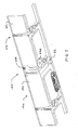
- Figure 1 is an isometric view showing the upper portions of an elongated edger member which embodies the concepts and principles of the invention;
- Figure 2 is an enlarged isometric fragmentary view depicting the upper areas of the elongated edger member of Fig. 1;
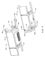
- Figure 3 is an isometric fragmentary view depicting the upper portions of an elongated edging assembly made up of two abutting edging members;
- Figure 4 is an exploded view similar to Fig. 3 but depicting the edging members in a vertically exploded relationship;
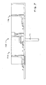
- Figure 5 is a top plan view depicting the assembly of Fig. 3;
- Figure 5A is an enlarged fragmentary view depicting the tongue component of the connector of Fig. 5;
- Figure 5B is an enlarged fragmentary view depicting the groove component of the connector of Fig. 5;
- Figure 6 is an isometric fragmentary view depicting the underneath areas of the left hand member of Fig. 3;
- Figure 7 is an angular fragmentary elevational view depicting the relationship between the edging assembly of Fig. 3 and a spike for holding the same against the ground;
- Figure 8 is a schematic view depicting the manner in which the assembly of Fig. 3 is used to define a landscape installation;
- Figure 9A is an isometric fragmentary view similar to Fig. 3 but depicting an alternative form of an elongated edging assembly which embodies the concepts and principles of the invention;
- Figure 9B is an isometric fragmentary view illustrating an alternative form of an elongated edger member similar to the member of Fig. 2 and which embodies the concepts and principles of the invention;
- Figure 9C is an isometric fragmentary view illustrating another alternative form of an elongated edger member similar to a member of the assembly of Fig. 9A and which embodies the concepts and principles of the invention;
- Figure 10 is an exploded isometric view depicting a packet of related objects which embodies the concepts and principles of the invention;
- Figure 11 is and an enlarged isometric view depicting the packet of accessories of Fig. 10;
- Figure 12 is a fragmentary front plan view showing the packet of related objects of Fig. 10; and
- Figure 13 is a cross-sectional view taken along the line 13-13 of Fig. 12.
- An elongated edger member 10 for holding landscaping materials and the like in place in a predetermined location which embodies the concepts and principles of the invention described herein is shown in Figs. 1 and 2. Commercial embodiments of the member 10 may typically be about 4 feet long; however, the length of member 10 is not a critical feature of the invention. Generally speaking, although again not a critical feature of the invention, member 10 may be formed by injection molding of a thermoplastic material such as polyethylene. In accordance with the invention, member 10, as shown particularly in Fig. 2, ideally may be used for holding landscaping materials and the like in place in a predetermined location. Alternative, more structurally fortified embodiments of the invention described below may desirably be used for holding paving materials such as paving stones or bricks and the like in place in a predetermined location.
- With particular reference to Fig. 2, it can be seen that member 10 may include an elongated upright
material retaining plate 12 and an outwardly extending support construct designated generally by thereference numeral 14. In use support construct 14 may sit on a ground surface, which me be prepared in advance if desired, and the same operates to holdupright plate 12 in position for retaining landscaping materials such as mulch and the like in a predetermined position. Support construct 14 generally may be arranged so as to extend longitudinally of plate 10 over essentially the entire length of the latter and the same may desirably be attached to asurface 26 of plate 10 adjacent a lower edge 17 thereof as shown. Desirably, but not necessarily,plate 12 and construct 14 may molded together to present a monolithic structure. In one particularly preferred embodiment,plate 12 may be about 2 inches in height and construct 14 may extend outwardly away fromplate 12 and away fromsurface 26 for about 2½ inches. -
Construct 14 may preferably be made up of a series or plurality of longitudinally spaced, outwardly extendingfooting structures 16, and ideally there may be a brace in the form of anail boss 18 positioned centrally on each footingstructure 16 as shown. As explained in greater detail hereinafter, the nail bosses or braces 18 may be used in conjunction with a spike to secure member 10 to a ground surface.Ribs 19 may desirably but not necessarily be provided as shown particularly in Fig. 2 for added rigidity and aesthetic value. In a particularly preferred embodiment discussed above, footingstructures 16 may all be essentially identical and the same may be ¾ inch wide and located on centerlines disposed approximately 4 inches apart. Desirably aseverable capping strip 15 may be included for added rigidity during handling and installation. - Member 10 also may include separate and discrete connectors 20, 22 disposed at respective opposite ends thereof. Connector 20 may include a component in the form of an elongated, upwardly extending
tongue 24 located onsurface 26 ofplate 12 nearend 28 of the latter. Connector 22 may include a component in the form of an elongated, upwardly extending tongue receiving groove 30 which is complementary totongue 24. Groove 30 may desirably be defined in ashelf 32 which extends in a longitudinal direction away from anend 34 ofplate 12. Preferably, groove 30 extends downwardly from anupper edge 35 ofplate 12 for only a short distance, ideally about ½ inch or so. In this latter regard, the groove could extend for essentially the entire height of the plate12; however, a shorter groove facilitates interconnection of abutting members 10. - As can be seen from Fig. 2,
tongue 24 and groove 30 are located onplate 12 near respective opposite ends 28, 34 thereof, and as will become more meaningful in the description which follows,tongue 24 and groove 30 are configured, adapted and arranged to cooperate such that if the member 10 were to be cut laterally into two separate longitudinally extending segments, each having a separate plate segment,tongue 24 and groove 30 would be able to interconnect the separate segments so that adjacent ends of the respective plate segments are in substantial abutting relationship and in substantial longitudinal alignment. - It is to be noted that member 10 also desirably includes a debris excluding shield 36 located at
end 34 ofplate 12. The purpose and function of shield 36 will be further explained and clarified hereinbelow. Suffice it to say at this point that shield 36 includes an upwardly extendingsegment 38 that projects longitudinally of member 10 away fromend 34 ofplate 12 and provides a mounting site forshelf 32 as shown. Moreover,segment 38 of shield 36 is arranged and configured to overlap an adjacent portion of a surface of another plate or plate segment disposed in abutting relationship to plate 12. Shield 36 also includes an outwardly extendingsegment 40 that projects longitudinally of member 10 away from anend 42 ofconstruct 14.Segment 40 of shield 36 is arranged and configured to overlap an adjacent portion of a surface of another construct or construct segment disposed in abutting relationship to construct 14. - Connector 22 further preferably includes a
bonnet 44 which extends longitudinally of member 10 fromend 42 ofconstruct 14, and it can be seen that in the preferred embodiment illustrated in Fig. 2,segment 40 provides a mounting site forbonnet 44. Suffice it to say at this point thatbonnet 44 and the nail boss 18' at theopposite end 43 ofconstruct 14 are configured, adapted and arranged to cooperate such that if the member 10 were to be cut laterally into two separate longitudinally extending segments, each having a separate construct segment,bonnet 44 and nail boss 18' would be able to interconnect the separate construct segments so that adjacent ends of the respective construct segments are in substantial abutting relationship and in substantial longitudinal alignment. In this regard it is to be appreciated that nail boss 18' is an element which is part of connector 20 andbonnet 44 is an element that is a part of connector 22. Thus,bonnet 44 and nail boss 18' present respective mating interengageable elements located at opposite ends ofconstruct 14. In the preferred embodiment shown in Fig. 2,segment 40 may be provided with abeveled edge 41 to facilitate molding. - With reference to Figs. 3 through 7, it can be seen that a plurality of members or segments of
members elongated edging assembly 100 for holding landscaping materials and the like in place in a predetermined location as illustrated particularly in Fig.7. In this regard, although Figs. 3 through 5 and 7 show only two segments of twoseparate members assembly 100, it will be readily understood by those skilled in the art that the system itself may include as many separate complete or segmental members 10 as might be needed to surround or define an area to be landscaped. In this regard it is also to be appreciated that in the illustrated preferred form of the invention, themembers members - As shown in Figs. 3 and 4, the
members groove 30a and the interengagement of nail boss 18'b in asocket 46a (best seen in Fig. 6) provided therefor in the underside ofbonnet 44a. Since in the preferred embodiment each individual piece of member 10 has complementary connectors at each end, the individual members and/or segments of the same may continue to be added to the system until the same is complete for a given area to be defined. Thus, the system may preferably includes respective mating interengageable components in the form ofgroove 30a and tongue 24b located onplates members ends 28b, 34a ofplates plates bonnet 44a located onsupport constructs 14a, 14b near ends 42a, 43b thereof, which elements also are configured and adapted to cooperate to interconnect themembers ends 42a, 43b of support constructs 14a, 14b in substantial abutting relationship and in substantial alignment, again as shown in Fig. 3. Unlike prior art systems, the invention described herein thus provides a secure connection holdingadjacent ends 34a, 28b of abuttingupright plates adjacent ends 34a, 28b of abuttingupright plates adjacent ends 42a, 43b of abutting support constructs 14a, 14b together. - In connection with the foregoing, it is to be appreciated that the footing structure 16b/nail boss 18b combinations desirably may all be identical so that any one of the same might perform the function of the nail boss 18'b. Thus, the
member 10b may be cut at any one of a variety of lengths for accommodating any given space requirements. - As described previously,
groove 30a and tongue 24b desirably are elongated and extend upwardly ofplates groove 30a and tongue 24b are arranged for interengagement by sliding of tongue 24b longitudinally and upwardly into and alonggroove 30a. On the other hand, as will be appreciated by those of ordinary skill in the art, the tongue and groove could be configured and arranged for lateral snapping of the tongue 24b into thegroove 30a. - With reference to Figs. 5, 5A and 5B, it can be seen that
groove 30a and tongue 24b desirably and preferably include a special complementary configuration which facilitates a secure interlocking interconnection therebetween. To this end, and with particular reference to Fig. 5A, it can be seen that tongue 24b is configured so as to present alongitudinally extending channel 60b disposed therebehind. And with reference to Fig. 5B, it can be seen thatgroove 30a is configured so as to include alongitudinally extending ridge 62a positioned to project intochannel 60b when tongue 24b andgroove 30a are interconnected as shown in Fig. 5. To facilitate a snap fit connection between tongue 24b andgroove 30a as mentioned above,ridge 62a may be flexibly configured and arranged and positioned so as to move out of the way while pushing tongue 24b laterally intogroove 30a and to snap back intochannel 60b when lateral insertion of tongue 24b is complete. - With further reference to Figs. 5, 5A, 5B, when two separate adjacent members or
segments abutment seam 48 is presented betweenplates segment 38a which desirably is located atend 34a ofplate 12a and is arranged and configured to overlapseam 48 as well as anadjacent portion 50b of surface 26b of anotherplate 12b disposed in abutting relationship toplate 12a.Desirably segment 38a extends vertically for the entire height of theplates segment 40a which desirably is located atend 42a ofsupport construct 14a and is arranged and configured to overlaphorizontal seam 54 as well as anadjacent portion 56b of surface 58b of another support construct 14b disposed in abutting relationship to supportconstruct 14a. - Fig. 6 illustrates the underside of
member 10a, which is provided with anangled ramp 64a which facilitates an injection molding process.Shoulders 66a, 68a provide abutment surfaces on opposite sides of theramp 64a to facilitate assembly and connection ofadjacent members shoulders 66a, 68a,end 42a ofmember 10a might tend to slide up on top of end 43b ofmember 10b during assembly or afterwards. - As shown in Fig. 4,
bonnet 44a may be provided with ahole 70a and nail boss 18'b may be provided with an hole 72b. When themembers holes 70a, 72b are aligned, and with reference to Fig. 7, it can be seen that aspike 71 may be inserted throughholes 70a, 72b for holdingmembers assembly 100 against the ground. - Fig. 8 is a cross-sectional view illustrating a landscaping installation where a series of members 10 (only one is shown) may be used to define a boundary between a
grassy area 74 and a landscapedarea 76 containing mulch or the like. To install members 10, soil is removed from thearea 76 to a depth sufficient to accommodate the height ofplate 12. Afirst member 10b may then be installed in a selected position and secured to the ground using spikes 71 b extending through one or more of the holes 72b in the nail bosses 18b of themember 10b. Starting from a position abovefirst member 10b (See Fig. 4),second member 10a may be moved downwardly while tongue 24b slides intogroove 30a. The downward movement ofmember 10a continues until nail boss 18'b ofmember 10b is encompassed and surrounded by thesocket 46a ofbonnet 44a ofmember 10a. Aspike 71 may then be inserted throughholes 70a, 72b as shown in Fig. 7 for holdingmembers assembly 100 consisting ofmembers bonnet 44a may be provided with opposed, generallyU-shaped openings 78a positioned to accommodate ribs 19b if the latter have been included as part of themember 10b in a given installation. - Fig. 9A illustrates an embodiment of the invention which is of particular value in connection with paving installations. Fig. 9A, which is similar to Fig. 3, illustrates an elongated edging assembly 200 of particular value for holding paving materials such as paving stones or bricks which are exposed to foot or vehicular traffic in a predetermined location. In this embodiment, the support constructs 214a, 214b may extend outwardly for a distance of as much as 4 inches from
plates 212a, 212b, and the latter may be 2½. to 3 inches in vertical height. Support constructs 214a, 214b may be thicker than support constructs 14a, 14b of Fig. 3 so as to help resist the additional loads imposed thereon by traffic, etc. In addition, themembers 210a, 210b may include gussets 280a, 280b in place of ribs 19a, 19b ofelongated edging assembly 100 of Fig. 3. The gussets 280a, 280b extend betweensurfaces 226a, 226b ofplates 212a, 212b and the nail bosses 218a, 218b. Otherwise, elongated edging assembly 200 of Fig. 9A may be essentially of the same general configuration asassembly 100 of Fig. 3. For commercial applications, eachmember 210a, 210b, etc. of the assembly 200 may desirably be 6 to 8 feet in length. - Fig. 9B illustrates an embodiment of the invention which is essentially the same as the embodiment of Fig. 2 except that in this case the
connector 422 of member 410 includes acover 493 for therib 419. To thisend cover 493 extends longitudinally and outwardly of member 410 fromsegments shield 436 as shown. Cover 493 desirably extends away frombonnet 444 on opposite sides thereof and presents atunnel member 494 that includes anoutboard portion 494a, an inboard arcuate portion 494b and a vertically extending portion 494c. Theupper section 432 of portion 494c ideally replaces and performs the same function asshelf 32 of Fig. 2.Tunnel member 494 presents and defines atunnel 495 which first extends horizontally throughportion 494a, then bends in portion 494b, and extends upwardly through portion 494c.Tunnel 495 has an interior configuration which is complementary to the outer shapes ofrib 419 andtongue 424 so as to provide a snug and secure fitting when adjacent members are interconnected to form an assembly. The upper portion oftunnel 495 presents and defines agroove 430 which interconnects withtongue 424 to serve essentially the same purpose as groove 30 of Fig. 2. Desirably in this embodiment thegroove 430 includes aridge 462 and thetongue 424 presents achannel 460 which are essentially the same as and provide the same respective functions as theridge 62a andchannel 60b of Figs 5A and 5B. - Fig. 9C illustrates an embodiment of the invention which is essentially the same as the embodiment of Fig. 9A except that in this case the
connector 522 ofmember 510 includes acover 593 for thegusset 580 and the interior of thetunnel 595 is configured to complement the exterior surfaces ofgusset 580. - Another important aspect of the invention is illustrated in Figs. 10 through 13. This aspect of the invention provides a
neat packet 300 of related objects. Generally speaking the related objects may be two of the elongated members 10 of Fig. 2 and several of thespikes 71 of Figs 7 and 8. In this regard it is to be noted (See Fig. 2) that elongated members 10 may be provided with a series of downwardly extendingholes 382 inupper edge 35 ofplate 12. In addition, the members 10 may be provided with a series ofupstanding pegs 386 located atop cappingstrip 15 ofsupport construct 14. Theseholes 382 and pegs 386 are positioned so that when twoseparate members 10c, 10d are brought together to form thepacket 300 as shown in Figs. 12 and 13, there will be ahole 382 for eachpeg 386 and vice versa. Themembers 10c, 10d are each essentially L-shaped in transverse cross-sectional configuration, and thepacket 300 created by bringing the same together has a generally rectangular transverse cross-sectional configuration. Thus, themembers 10c, 10d are configured, arranged, aligned and joined together so as to present a single, elongated construct having anopen interior 388. - The
packet 300 desirably may include one or more accessory items for themembers 10c, 10d. Ideally, these accessory items may comprise one or more of thespikes 371 which may be part of apack 389 that includes a securing element in the form of aspider element 390 provided with opposed mountingprojections 392. Desirably thespikes 371 and thespider element 390 may be molded together as a single item (See Fig. 11). As discussed above,members 10c, 10d, which may desirably be identical with the members 10 and with each other, may includeholes 72c, 72d provided innail bosses 18c, 18d. Theseholes 72c, 72d are positioned so as to open into theinterior 388 of thepacket 300. Thespider element 390 with the attachedspikes 371 may then desirably be mounted withinopen interior 388 with theprojections 392 positioned within theholes 72c, 72d. - In another embodiment of the invention, the
pack 389 may include a securing element in the form of a blister pack containing the nails which may desirably be made of steel. In this embodiment of the invention the mountingprojections 392 may be formed as part of or as an attachment to the blister pack.
Claims (18)
- An elongated edging assembly for holding landscaping and/or paving materials and the like in place in a predetermined location, said assembly comprising:a first elongated edger member including a first elongated upright material retaining plate and a connector located adjacent an end of the first member; anda second elongated edger member including a second elongated upright material retaining plate and a connector located adjacent an end of the second member,said connectors including respective mating interengageable components located on said plates near said ends thereof,said components being configured and adapted to cooperate to interconnect said members and maintain the ends of the respective plates in substantial abutting relationship with the plates in substantial alignment.
- An assembly as set forth in claim 1, wherein said mating components include a tongue on one of the plates and a complementary tongue receiving groove on another of the plates.
- An assembly as set forth in 2, wherein said tongue and said groove are elongated and extend upwardly of said plates.
- An assembly as set forth in claim 1, and a debris excluding shield located at the end of one of the plates, said shield being configured and arranged to overlap an adjacent portion of a surface of the other plate.
- An assembly as set forth in claim 2, wherein said tongue and said groove are configured and arranged for engagement by longitudinal sliding of the tongue into the groove.
- An assembly as set forth in claim 1, wherein said connectors are configured and arranged for engagement by snapping one connector into the other.
- An elongated edging member for holding landscaping and/or paving materials and the like in place in a predetermined location, said member comprising:an elongated upright material retaining plate;a first connector including a first component located on said plate near an end thereof; anda second connector including a second component located on said plate near an opposite end thereof,said components being configured, adapted and arranged to cooperate such that if the member were to be cut laterally into said two separate longitudinally extending segments, each having a separate plate segment, said connectors would be able to interconnect the segments of the member so that adjacent ends of the respective plate segments are in substantial abutting relationship and in substantial longitudinal alignment.
- An edging member as set forth in claim 7, wherein said mating components include a tongue at one end of the plate and a complementary tongue receiving groove at an opposite end of the plate.
- An edging member as set forth in claim 7, wherein said member includes an outwardly extending support construct arranged and configured so as to extend longitudinally of the plate, and said connectors include respective mating, interengageable elements located at opposite ends of said support construct.
- An edging member as set forth in claim 7, and a debris excluding shield located at an end of the plate, said shield being configured and arranged to overlap an adjacent portion of a surface of another plate or plate segment.
- An elongated edging assembly for holding landscaping and/or paving materials and the like in place in a predetermined location, said assembly comprising:a first elongated edger member including a first elongated upright material retaining plate and a outwardly extending support construct attached to the first plate;a second elongated edger member including a second elongated upright material retaining plate and a outwardly extending support construct attached to the second plate, said edger members being adapted and arranged for being interconnected in longitudinal alignment with adjacent ends of the respective plates in substantial abutting relationship presenting an abutment seam therebetween; anda debris excluding shield located at the end of the first plate, said shield including a first segment disposed and configured to overlap said seam, said shield including a second segment disposed in contact with the support construct of the other of said members when the members are in said abutting relationship.
- An assembly as set forth in claim 11, wherein said first segment of the shield is disposed and configured to overlap part of a surface of the plate of the other of said members.
- An assembly as set forth in claim 11, wherein said second segment of the shield is disposed and configured to overlap part of an upper surface of the support construct of the other of said members.
- A packet of related objects comprising:a pair of elongated pieces, each piece having a generally L-shaped transverse cross-sectional configuration, said pieces being configured, arranged, aligned and joined together so as to present a single elongated construct having an open interior and a generally rectangular transverse cross-sectional configuration; anda pack comprising at least one accessory item for said elongated pieces,said pack including a securing element having at least one mounting projection,at least one of said elongated pieces having a mounting hole provided therein, said hole being positioned so as to open into the interior of the construct,said securing element being mounted in said interior with said projection extending into said hole.
- A packet as set forth in claim 14, wherein said pieces are lengths of plastic edging and said accessory is a spike for holding at least one of the pieces in position on the ground.
- A packet as set forth in claim 14, wherein said pieces are identical.
- A packet as set forth in claim 16, wherein said pieces are lengths of plastic edging and said pack includes a plurality of said accessories, said accessories being spikes for holding the pieces in position on the ground.
- An assembly as set forth in claim 8, wherein one of said elements is one of said braces and the other of said elements comprises a bonnet for said one of said braces and a cover for its corresponding rib.
Applications Claiming Priority (1)
| Application Number | Priority Date | Filing Date | Title |
|---|---|---|---|
| US11/543,573 US7774993B2 (en) | 2006-10-05 | 2006-10-05 | Elongated edging assembly |
Publications (2)
| Publication Number | Publication Date |
|---|---|
| EP1908343A2 true EP1908343A2 (en) | 2008-04-09 |
| EP1908343A3 EP1908343A3 (en) | 2009-04-22 |
Family
ID=38865455
Family Applications (1)
| Application Number | Title | Priority Date | Filing Date |
|---|---|---|---|
| EP07253871A Withdrawn EP1908343A3 (en) | 2006-10-05 | 2007-09-28 | Elongated edging assembly |
Country Status (4)
| Country | Link |
|---|---|
| US (2) | US7774993B2 (en) |
| EP (1) | EP1908343A3 (en) |
| JP (1) | JP2008095493A (en) |
| CA (1) | CA2605136C (en) |
Cited By (1)
| Publication number | Priority date | Publication date | Assignee | Title |
|---|---|---|---|---|
| WO2018041512A1 (en) * | 2016-09-02 | 2018-03-08 | Martin Jansen | System for delimiting the edge of a ground surface |
Families Citing this family (19)
| Publication number | Priority date | Publication date | Assignee | Title |
|---|---|---|---|---|
| US7963718B2 (en) * | 2008-03-17 | 2011-06-21 | Permaloc Corporation | Edge restraint for water permeable pavement systems |
| US9109337B2 (en) * | 2008-05-20 | 2015-08-18 | Novel Ideas, Inc. | Landscape edging system |
| US9345199B2 (en) * | 2009-01-28 | 2016-05-24 | Oldcastle Precast, Inc. | Landscape edger with adjustable connection mechanism |
| USD615673S1 (en) | 2009-10-07 | 2010-05-11 | Oldcastle Precast, Inc. | Landscape edger |
| USD617012S1 (en) | 2009-11-23 | 2010-06-01 | Oldcastle Precast, Inc. | Landscape edger |
| US20120276342A1 (en) * | 2011-01-28 | 2012-11-01 | Patrick Dudley Bray | Artificial surface divider |
| US9043960B2 (en) | 2012-12-14 | 2015-06-02 | Jeffrey Ballard | Landscape edging connector |
| US9232698B1 (en) * | 2013-10-11 | 2016-01-12 | Deidra Williams | Edging device |
| US9974240B1 (en) * | 2015-01-12 | 2018-05-22 | EZ Concepts LLC | Simulated stone landscape edging apparatus |
| US20160286730A1 (en) * | 2015-03-31 | 2016-10-06 | Tom Holsworth | Support track system for landscaping materials |
| US10544549B2 (en) * | 2015-08-11 | 2020-01-28 | Pro Grass LLC | Athletic field safety border |
| USRE49472E1 (en) | 2018-01-04 | 2023-03-28 | Toolbro Innovators, Llc | Stake securing a landscaping edging strip |
| US10729077B2 (en) * | 2018-04-27 | 2020-08-04 | Toolbro Innovators, Llc | Edging member, system, and arrangement for landscaping or paving |
| US10662607B2 (en) * | 2018-08-21 | 2020-05-26 | Jesse B. Trebil | Water drainage edging |
| US11957095B2 (en) | 2019-10-21 | 2024-04-16 | Stanley Fischer | Modular landscape border system |
| US11026374B2 (en) * | 2019-10-31 | 2021-06-08 | Kyle GUERRINI | Landscaping support component |
| US11598109B1 (en) * | 2021-12-22 | 2023-03-07 | 3DM Tool LLC | Track system for placing shaped bodies |
| US12331535B1 (en) * | 2022-02-17 | 2025-06-17 | Kevin O'Donnell | Roof-mounted safety foothold |
| US12516478B2 (en) * | 2022-07-20 | 2026-01-06 | David S. Orton | Edge restraint system for pavers |
Citations (4)
| Publication number | Priority date | Publication date | Assignee | Title |
|---|---|---|---|---|
| USRE33550E (en) | 1987-10-02 | 1991-03-12 | Restraint edge for paving members | |
| US5240343A (en) | 1989-12-12 | 1993-08-31 | Snap Edge Corporation | Holding device for paving blocks |
| US6071038A (en) | 1998-09-02 | 2000-06-06 | Strobl, Jr.; Frederick P. | Device for holding paving blocks in position |
| US6409421B1 (en) | 1998-05-11 | 2002-06-25 | Stephen Jones | Overlapping connector for an edge restraint |
Family Cites Families (34)
| Publication number | Priority date | Publication date | Assignee | Title |
|---|---|---|---|---|
| US329709A (en) * | 1885-11-03 | Mowing-machine | ||
| US113007A (en) * | 1871-03-28 | Improvement in combined bordering and drain-tiles | ||
| US336220A (en) * | 1886-02-16 | John n | ||
| US456995A (en) * | 1891-08-04 | Metallic curbing | ||
| US567173A (en) * | 1896-09-08 | Curb and gutter | ||
| US516228A (en) * | 1894-03-13 | shailer | ||
| US2821809A (en) * | 1956-05-25 | 1958-02-04 | James C Collien | Metal edging |
| US3916563A (en) * | 1974-07-01 | 1975-11-04 | George E Tedesh | Lawn edge trim guard |
| US4831776A (en) * | 1986-03-11 | 1989-05-23 | Fritch John R | Landscape edging apparatus and method |
| US5377447A (en) * | 1986-03-11 | 1995-01-03 | Fritch; John R. | Landscape edging apparatus and method |
| US4863307A (en) * | 1987-10-02 | 1989-09-05 | Stephen Jones | Restraint edge for paving members |
| US4969289A (en) * | 1988-10-14 | 1990-11-13 | Carmen Trifiletti | Garden edging device |
| US5073061A (en) * | 1990-04-16 | 1991-12-17 | Stephen Jones | Industrial restraint edging system for segmented paving units |
| USD329709S (en) * | 1990-04-24 | 1992-09-22 | Strobl Jr Frederick P | Edge restraint for paving blocks |
| US5092076A (en) * | 1991-01-04 | 1992-03-03 | Terreta Joseph P | Planter edging landscaping system |
| USD336220S (en) | 1991-03-22 | 1993-06-08 | Grimes Gerald A | Interlocking lawn and garden bed edging |
| US5168678A (en) * | 1991-11-07 | 1992-12-08 | Thompson Industries, Inc. | Modular landscaping system and structures |
| US5259154A (en) * | 1992-02-14 | 1993-11-09 | Lilley Eugene H | Landscape border |
| US5666682A (en) * | 1994-09-30 | 1997-09-16 | Bonaddio; Vincenzo A. | Mattress pad of adjustable size |
| US5720128A (en) * | 1995-06-19 | 1998-02-24 | Smith; David A. | Landscape edging system |
| IT242332Y1 (en) * | 1996-02-09 | 2001-06-14 | Edil Plast Srl | MODULAR AND MODULAR CHANNEL FOR THE FORMATION OF SCHOOL CHANNELS WITH WALKABLE AND / OR DRIVEABLE GRID. |
| US5806249A (en) * | 1996-06-28 | 1998-09-15 | Helms; Joe L. | Plastic timber landscaping system |
| US6012254A (en) * | 1996-11-02 | 2000-01-11 | Gaston; Johannes N. | Trenchless landscape edging system |
| US5769562A (en) * | 1997-01-08 | 1998-06-23 | Jones; Stephen | Edge restraint apparatus having variable length sections |
| US6030144A (en) * | 1997-01-14 | 2000-02-29 | Cannella; Samuel Michael | Edging resistant system for paving blocks |
| US5930947A (en) * | 1997-08-19 | 1999-08-03 | Eckhoff; Gerald J. | Landscape system apparatus |
| US6085458A (en) * | 1997-12-31 | 2000-07-11 | Gau; Larry J. | Lawn edging |
| DE19848320A1 (en) | 1998-10-20 | 2000-05-18 | Stefan Flabb | Connecting system for prefabricated concrete elements has push-fit connection with connecting parts of solid but resilient plastics inserted in concrete elements and having recess and shoulder |
| CA2278953C (en) * | 1999-07-23 | 2008-04-22 | Permaloc Corporation | Method and apparatus for providing an edging structure for pavement |
| CA2290836C (en) * | 1999-11-25 | 2002-12-31 | Michael Mcintyre | Integrally moulded plastic landscape edging strip and spikes |
| US6354038B1 (en) * | 2000-06-22 | 2002-03-12 | Bert W. Morris | Gardening barrier |
| DE10230182A1 (en) | 2002-07-05 | 2004-01-22 | Adolf Fenske | Edging strip for garden beds comprises solid or hollow profile with horizontal support strip at its base on one side, profiles being connected together by ribs which fit into grooves |
| GB0305374D0 (en) * | 2003-03-10 | 2003-04-16 | Turner Intellect Property Ltd | Wall plug pack |
| USD516228S1 (en) | 2005-02-24 | 2006-02-28 | Dunbar Gerald N | Paving block holder |
-
2006
- 2006-10-05 US US11/543,573 patent/US7774993B2/en active Active
-
2007
- 2007-09-28 EP EP07253871A patent/EP1908343A3/en not_active Withdrawn
- 2007-10-02 CA CA2605136A patent/CA2605136C/en active Active
- 2007-10-04 JP JP2007260784A patent/JP2008095493A/en active Pending
-
2010
- 2010-07-30 US US12/846,994 patent/US20100293871A1/en not_active Abandoned
Patent Citations (6)
| Publication number | Priority date | Publication date | Assignee | Title |
|---|---|---|---|---|
| USRE33550E (en) | 1987-10-02 | 1991-03-12 | Restraint edge for paving members | |
| US5240343A (en) | 1989-12-12 | 1993-08-31 | Snap Edge Corporation | Holding device for paving blocks |
| US5375941A (en) | 1989-12-12 | 1994-12-27 | Snap Edge Cororation | Holding device for paving blocks |
| US6409421B1 (en) | 1998-05-11 | 2002-06-25 | Stephen Jones | Overlapping connector for an edge restraint |
| US6767159B2 (en) | 1998-05-11 | 2004-07-27 | Stephen Jones | Overlapping connector for an edge restraint |
| US6071038A (en) | 1998-09-02 | 2000-06-06 | Strobl, Jr.; Frederick P. | Device for holding paving blocks in position |
Cited By (1)
| Publication number | Priority date | Publication date | Assignee | Title |
|---|---|---|---|---|
| WO2018041512A1 (en) * | 2016-09-02 | 2018-03-08 | Martin Jansen | System for delimiting the edge of a ground surface |
Also Published As
| Publication number | Publication date |
|---|---|
| JP2008095493A (en) | 2008-04-24 |
| US20080104896A1 (en) | 2008-05-08 |
| US20100293871A1 (en) | 2010-11-25 |
| CA2605136A1 (en) | 2008-04-05 |
| US7774993B2 (en) | 2010-08-17 |
| CA2605136C (en) | 2011-07-05 |
| EP1908343A3 (en) | 2009-04-22 |
Similar Documents
| Publication | Publication Date | Title |
|---|---|---|
| CA2605136C (en) | Elongated edging assembly | |
| CA2597081C (en) | Paved surface restraint and method of installation | |
| US6012254A (en) | Trenchless landscape edging system | |
| US9345199B2 (en) | Landscape edger with adjustable connection mechanism | |
| US5377447A (en) | Landscape edging apparatus and method | |
| EP1275294B1 (en) | Lawn edging | |
| US5456045A (en) | Lawn edging strip | |
| US4976063A (en) | Lawn edging system and associated edging components | |
| US4190384A (en) | Concrete construction element system for erecting plant accommodating walls | |
| US6071038A (en) | Device for holding paving blocks in position | |
| US12201066B2 (en) | Six-device-in-one material-saving consumer-and-manufacturer-cost-saving shipping-volume-saving multi-barrier-locking multi-root-gripping-and-water-flowing anti-digging garden-and-tree-protecting vertical-truck-bed-extender-and-tonneau-cover stackable landscape barrier | |
| CA2260442A1 (en) | Paver block edging system | |
| US6643977B1 (en) | Ground engaging boundary element | |
| US6502349B1 (en) | Lawn and garden edging device | |
| US7669365B2 (en) | Lawn edging | |
| US20140259902A1 (en) | Landscape edging system | |
| US6182948B1 (en) | Modular garden border system | |
| US20060283114A1 (en) | Decorative borders | |
| CA2533097C (en) | Lawn edging device | |
| CA2727884C (en) | Landscape edger with adjustable connection mechanism | |
| AU759806B2 (en) | A ground engaging boundary element | |
| KR100590422B1 (en) | Slope protection vegetation block | |
| CA2369256A1 (en) | Curbing for paving stones | |
| GB2376863A (en) | Lawn edge strip |
Legal Events
| Date | Code | Title | Description |
|---|---|---|---|
| PUAI | Public reference made under article 153(3) epc to a published international application that has entered the european phase |
Free format text: ORIGINAL CODE: 0009012 |
|
| AK | Designated contracting states |
Kind code of ref document: A2 Designated state(s): AT BE BG CH CY CZ DE DK EE ES FI FR GB GR HU IE IS IT LI LT LU LV MC MT NL PL PT RO SE SI SK TR |
|
| AX | Request for extension of the european patent |
Extension state: AL BA HR MK RS |
|
| PUAL | Search report despatched |
Free format text: ORIGINAL CODE: 0009013 |
|
| AK | Designated contracting states |
Kind code of ref document: A3 Designated state(s): AT BE BG CH CY CZ DE DK EE ES FI FR GB GR HU IE IS IT LI LT LU LV MC MT NL PL PT RO SE SI SK TR |
|
| AX | Request for extension of the european patent |
Extension state: AL BA HR MK RS |
|
| AKX | Designation fees paid | ||
| REG | Reference to a national code |
Ref country code: DE Ref legal event code: 8566 |
|
| STAA | Information on the status of an ep patent application or granted ep patent |
Free format text: STATUS: THE APPLICATION IS DEEMED TO BE WITHDRAWN |
|
| 18D | Application deemed to be withdrawn |
Effective date: 20091023 |