EP1908046B1 - Card with pocket - Google Patents
Card with pocket Download PDFInfo
- Publication number
- EP1908046B1 EP1908046B1 EP06786605A EP06786605A EP1908046B1 EP 1908046 B1 EP1908046 B1 EP 1908046B1 EP 06786605 A EP06786605 A EP 06786605A EP 06786605 A EP06786605 A EP 06786605A EP 1908046 B1 EP1908046 B1 EP 1908046B1
- Authority
- EP
- European Patent Office
- Prior art keywords
- substrate
- card
- cavity
- substrates
- Prior art date
- Legal status (The legal status is an assumption and is not a legal conclusion. Google has not performed a legal analysis and makes no representation as to the accuracy of the status listed.)
- Not-in-force
Links
- 239000000758 substrate Substances 0.000 claims abstract description 154
- 229920003023 plastic Polymers 0.000 claims abstract description 20
- 230000000007 visual effect Effects 0.000 claims 1
- 238000000034 method Methods 0.000 description 25
- 239000000463 material Substances 0.000 description 24
- 238000003475 lamination Methods 0.000 description 10
- 238000004519 manufacturing process Methods 0.000 description 4
- 230000004888 barrier function Effects 0.000 description 3
- 239000011248 coating agent Substances 0.000 description 3
- 238000000576 coating method Methods 0.000 description 3
- 239000007787 solid Substances 0.000 description 3
- 238000005520 cutting process Methods 0.000 description 2
- 238000010586 diagram Methods 0.000 description 2
- 230000000694 effects Effects 0.000 description 2
- 238000010030 laminating Methods 0.000 description 2
- 239000000853 adhesive Substances 0.000 description 1
- 230000001070 adhesive effect Effects 0.000 description 1
- UBAZGMLMVVQSCD-UHFFFAOYSA-N carbon dioxide;molecular oxygen Chemical compound O=O.O=C=O UBAZGMLMVVQSCD-UHFFFAOYSA-N 0.000 description 1
- 238000005034 decoration Methods 0.000 description 1
- 230000007547 defect Effects 0.000 description 1
- 230000001419 dependent effect Effects 0.000 description 1
- 239000007789 gas Substances 0.000 description 1
- 239000002650 laminated plastic Substances 0.000 description 1
- 230000035699 permeability Effects 0.000 description 1
Images


Classifications
-
- A—HUMAN NECESSITIES
- A45—HAND OR TRAVELLING ARTICLES
- A45C—PURSES; LUGGAGE; HAND CARRIED BAGS
- A45C13/00—Details; Accessories
- A45C13/42—Devices for identifying luggage; Means for attaching same
-
- A—HUMAN NECESSITIES
- A45—HAND OR TRAVELLING ARTICLES
- A45C—PURSES; LUGGAGE; HAND CARRIED BAGS
- A45C11/00—Receptacles for purposes not provided for in groups A45C1/00-A45C9/00
- A45C11/18—Ticket-holders or the like
- A45C11/182—Credit card holders
-
- B—PERFORMING OPERATIONS; TRANSPORTING
- B32—LAYERED PRODUCTS
- B32B—LAYERED PRODUCTS, i.e. PRODUCTS BUILT-UP OF STRATA OF FLAT OR NON-FLAT, e.g. CELLULAR OR HONEYCOMB, FORM
- B32B27/00—Layered products comprising a layer of synthetic resin
- B32B27/06—Layered products comprising a layer of synthetic resin as the main or only constituent of a layer, which is next to another layer of the same or of a different material
- B32B27/08—Layered products comprising a layer of synthetic resin as the main or only constituent of a layer, which is next to another layer of the same or of a different material of synthetic resin
-
- B—PERFORMING OPERATIONS; TRANSPORTING
- B32—LAYERED PRODUCTS
- B32B—LAYERED PRODUCTS, i.e. PRODUCTS BUILT-UP OF STRATA OF FLAT OR NON-FLAT, e.g. CELLULAR OR HONEYCOMB, FORM
- B32B27/00—Layered products comprising a layer of synthetic resin
- B32B27/30—Layered products comprising a layer of synthetic resin comprising vinyl (co)polymers; comprising acrylic (co)polymers
- B32B27/304—Layered products comprising a layer of synthetic resin comprising vinyl (co)polymers; comprising acrylic (co)polymers comprising vinyl halide (co)polymers, e.g. PVC, PVDC, PVF, PVDF
-
- B—PERFORMING OPERATIONS; TRANSPORTING
- B42—BOOKBINDING; ALBUMS; FILES; SPECIAL PRINTED MATTER
- B42F—SHEETS TEMPORARILY ATTACHED TOGETHER; FILING APPLIANCES; FILE CARDS; INDEXING
- B42F7/00—Filing appliances without fastening means
- B42F7/02—Filing appliances comprising only one pocket or compartment, e.g. single gussetted pockets
- B42F7/025—Filing appliances comprising only one pocket or compartment, e.g. single gussetted pockets made of transparent material
-
- B—PERFORMING OPERATIONS; TRANSPORTING
- B42—BOOKBINDING; ALBUMS; FILES; SPECIAL PRINTED MATTER
- B42F—SHEETS TEMPORARILY ATTACHED TOGETHER; FILING APPLIANCES; FILE CARDS; INDEXING
- B42F7/00—Filing appliances without fastening means
- B42F7/06—Filing appliances comprising a plurality of pockets or compartments, e.g. portfolios or cases with a plurality of compartments
- B42F7/065—Filing appliances comprising a plurality of pockets or compartments, e.g. portfolios or cases with a plurality of compartments made of transparent material
-
- G—PHYSICS
- G09—EDUCATION; CRYPTOGRAPHY; DISPLAY; ADVERTISING; SEALS
- G09F—DISPLAYING; ADVERTISING; SIGNS; LABELS OR NAME-PLATES; SEALS
- G09F1/00—Cardboard or like show-cards of foldable or flexible material
-
- G—PHYSICS
- G09—EDUCATION; CRYPTOGRAPHY; DISPLAY; ADVERTISING; SEALS
- G09F—DISPLAYING; ADVERTISING; SIGNS; LABELS OR NAME-PLATES; SEALS
- G09F1/00—Cardboard or like show-cards of foldable or flexible material
- G09F1/10—Supports or holders for show-cards
-
- G—PHYSICS
- G09—EDUCATION; CRYPTOGRAPHY; DISPLAY; ADVERTISING; SEALS
- G09F—DISPLAYING; ADVERTISING; SIGNS; LABELS OR NAME-PLATES; SEALS
- G09F3/00—Labels, tag tickets, or similar identification or indication means; Seals; Postage or like stamps
- G09F3/08—Fastening or securing by means not forming part of the material of the label itself
- G09F3/18—Casings, frames or enclosures for labels
- G09F3/20—Casings, frames or enclosures for labels for adjustable, removable, or interchangeable labels
-
- B—PERFORMING OPERATIONS; TRANSPORTING
- B32—LAYERED PRODUCTS
- B32B—LAYERED PRODUCTS, i.e. PRODUCTS BUILT-UP OF STRATA OF FLAT OR NON-FLAT, e.g. CELLULAR OR HONEYCOMB, FORM
- B32B2250/00—Layers arrangement
- B32B2250/04—4 layers
-
- B—PERFORMING OPERATIONS; TRANSPORTING
- B32—LAYERED PRODUCTS
- B32B—LAYERED PRODUCTS, i.e. PRODUCTS BUILT-UP OF STRATA OF FLAT OR NON-FLAT, e.g. CELLULAR OR HONEYCOMB, FORM
- B32B2250/00—Layers arrangement
- B32B2250/24—All layers being polymeric
-
- B—PERFORMING OPERATIONS; TRANSPORTING
- B32—LAYERED PRODUCTS
- B32B—LAYERED PRODUCTS, i.e. PRODUCTS BUILT-UP OF STRATA OF FLAT OR NON-FLAT, e.g. CELLULAR OR HONEYCOMB, FORM
- B32B2307/00—Properties of the layers or laminate
- B32B2307/40—Properties of the layers or laminate having particular optical properties
- B32B2307/41—Opaque
-
- B—PERFORMING OPERATIONS; TRANSPORTING
- B32—LAYERED PRODUCTS
- B32B—LAYERED PRODUCTS, i.e. PRODUCTS BUILT-UP OF STRATA OF FLAT OR NON-FLAT, e.g. CELLULAR OR HONEYCOMB, FORM
- B32B2307/00—Properties of the layers or laminate
- B32B2307/40—Properties of the layers or laminate having particular optical properties
- B32B2307/412—Transparent
-
- B—PERFORMING OPERATIONS; TRANSPORTING
- B32—LAYERED PRODUCTS
- B32B—LAYERED PRODUCTS, i.e. PRODUCTS BUILT-UP OF STRATA OF FLAT OR NON-FLAT, e.g. CELLULAR OR HONEYCOMB, FORM
- B32B2425/00—Cards, e.g. identity cards, credit cards
-
- B—PERFORMING OPERATIONS; TRANSPORTING
- B32—LAYERED PRODUCTS
- B32B—LAYERED PRODUCTS, i.e. PRODUCTS BUILT-UP OF STRATA OF FLAT OR NON-FLAT, e.g. CELLULAR OR HONEYCOMB, FORM
- B32B2439/00—Containers; Receptacles
- B32B2439/02—Open containers
-
- B—PERFORMING OPERATIONS; TRANSPORTING
- B32—LAYERED PRODUCTS
- B32B—LAYERED PRODUCTS, i.e. PRODUCTS BUILT-UP OF STRATA OF FLAT OR NON-FLAT, e.g. CELLULAR OR HONEYCOMB, FORM
- B32B2571/00—Protective equipment
Definitions
- the present invention relates generally to a card having a pocket, and more specifically to a substantially planar laminated plastic card, such as a financial card, gift card, luggage tag, etc., having an integral pocket and a method for manufacturing the same.
- Standard financial and gift cards generally comprise a plurality of substrates and films laminated together. While such financial and gift cards according to the prior art provide a number of advantageous features, they nevertheless have certain limitations.
- the present invention seeks to overcome certain of these limitations and other drawbacks of the prior art, and to provide new features not heretofore available. A full discussion of the features and advantages of the present invention is deferred to the following detailed description, which proceeds with reference to the accompanying drawings.
- US Patent no. 2,898,257 discloses a combined card mount and pocket and a method of making the same.
- a first embodiment of the invention provides a pocket card as detailed in claim 1.
- Advantageous embodiments are provided in the dependent claims.
- FIG. 1 is a perspective view of one embodiment of a card having a pocket
- FIG. 2 is an exploded perspective view of the card of FIG. 1 ;
- FIG. 3 is side cross-sectional view of the card through line 3-3 of FIG. 1 ;
- FIG. 4 is an end elevation view of the card of FIG. 1 ;
- FIG. 5 is a top plan view of a layer of the card of FIG. 1 , showing one embodiment of a laminating-free mask;
- FIG. 6 is an exploded perspective view of another embodiment of card having a plurality of pockets
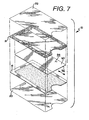
- FIG. 7 is an exploded perspective view of another embodiment of a card having a pocket with a pull-out pocket-forming member
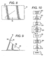
- FIG. 8 is a rear plan view of another embodiment of a card having a stand
- FIG. 9 is a side elevation view of the embodiment of FIG. 8 ;
- FIG. 10 is a schematic flow diagram of one embodiment of a process for manufacturing a card having a pocket.
- the card 10 having at least one cavity or pocket 12.
- the card 10 comprises a plurality of layers of material joined at their periphery to create the cavity or pocket 12, and an opening 14 provided at one side of the card 10 providing access to the cavity 12.
- removable inserts such as pictures, can be placed into the cavity 12 through the opening 14 in the card 10.
- the card 10 takes the form of a financial card, bank card, gift card, etc., and has a size which meets CR80 specifications.
- planar i.e., generally flat
- rigid i.e., it is able to maintain its form and shape, but can still be flexed and bent to a degree without breaking and will return to its original shape.
- the card 10 contains a first cavity 12.
- the card 10 comprises a first substrate 16, a second substrate 18, a first covering 20 and a second covering 22, however, an alternate embodiment may be created without utilizing the first and second coverings 20, 22.
- This embodiment also utilizes a first mask 24 and a second mask 26 to assist in defining the pocket 12 and opening 14 thereto.
- the first substrate 16 is generally made of a generally rigid plastic material (the term plastic and plastic material herein universally refers to any polymeric material), and is substantially planar in its finished form. Additionally, in a preferred embodiment the first substrate 16 is generally opaque. This may be accomplished through material properties, or through a coating, such as a printing on its surface to appear non-transparent. Alternatively, the first substrate 16 could be transparent. In a preferred embodiment, the first substrate 16 is made of an 8 mil. solid core white PVC material, however, it is understood that thinner or thicker substrates, as well as different materials, may be utilized. The material may be provided in sheet or roll form.
- the first substrate 16 has a first surface 28 and a second surface 30 opposing the first surface 28.
- the first substrate 16 also has a plurality of sides.
- the first substrate 16 has a first side 32, a second side 34 opposing the first side 32, a third side 36 and a fourth side 38 opposing the third side 36.
- the sides 32, 34, 36 and 38 of the first substrate 16 define a perimeter.
- the second substrate 18 is also generally made of a generally rigid plastic material, and is substantially planar in its finished form. In one embodiment, however, instead of being generally opaque like the first substrate 16, the second substrate 18 is generally clear or transparent. Alternatively, the second substrate 18 could also be opaque. Additionally, in a preferred embodiment the second substrate 18 is made of an 8 mm. solid core PVC material, however, it is understood that thinner or thicker substrates, as well as different materials, may be utilized. The material may be provided in sheet or roll form.
- the second substrate 18 has a first surface 40 and a second surface 42 opposing the first surface 40.
- the second substrate 18 also has a plurality of sides.
- the second substrate 18 has a first side 44, a second side 46 opposing the first side 44, a third side 48 and a fourth side 50 opposing the third side 48.
- the sides 44, 45, 48 and 50 of the second substrate 18 define a perimeter thereof.
- first surface 28 of the first substrate 16 is secured or connected to a portion of the first surface 40 of the second substrate 18, and in one embodiment they are laminated together.
- first and second substrates 16, 18 are secured to one another at a portion adjacent the perimeters thereof to define the cavity 12 therebetween.
- a portion of the first surface 28 adjacent the first side 32 of the first substrate 16 is connected to a portion of the first surface 40 adjacent the first side 44 of the second substrate 18, a portion of the first surface 28 adjacent the second side 34 of the first substrate 16 is connected to a portion of the first surface 40 adjacent the second side 46 of the second substrate 18, and a portion of the first surface 28 adjacent the third side 36 of the first substrate 16 is connected to a portion of the first surface 40 adjacent the third side 48 of the second substrate 18.
- the area between the connected portions is the cavity 12.
- An end view of the open cavity is shown in FIG. 4 .
- a portion of the first surface 28 adjacent the fourth side 38 of the first substrate 16 may be connected to a portion of the first surface 40 adjacent the fourth side 50 of the second substrate 18, thereby making the opening 14 smaller. If a portion of the first and second substrates 16, 18 adjacent the fourth sides 38, 50 thereof are connected, the portions generally are those also adjacent the first and third sides 32 and 44, and 36 and 48, respectively, thereof.
- a notch 19 may be provided in the card 10 adjacent the opening 14 to assist in inserting and removing items from the cavity 12.
- the notch 19 is typically provided in each layer of the card 10 during die cutting thereof, however, it is understood that the notch 19 may be provided in less than all the layers without departing from the scope of the present invention.
- An additional aperture 21 may also be provided in the card 10 to allow a strap or other component to be inserted therethrough, such as for a luggage identifier.
- the portion of the perimeter (i.e., adjacent the sides of the substrates 16,18) of the first and second substrates 16, 18 that are connected extends from approximately the edge of the sides and extends a distance inward.
- the portion of the perimeter may extend approximately 0.3175 cm (0.125”) or 0.635 cm (0.250") inward from the edge of the side, however, the range of the portion of the surfaces that are connected may be from less than 0.254 cm (0.100") wide to at least 0.9525 cm (0.375") wide, and any distance therebetween, however it is understood that the distance of the portion of the surfaces that are connected may be narrower or wider without departing from the scope of the present invention.
- the portion of the first and second substrates 16, 18 that are connected together is that portion that is exterior of the mask.
- the mask is generally a component that shields a surface from the effects of any bonding or lamination process, should that surface be subject to any such processes.
- the masks 24, 26 effectively provide a lamination-free zone and the non-masked portions will therefore define the laminated or bonded area operating as the frame or perimeter of the pocket 12, as well as the opening 14 to the pocket 12.
- the first substrate 16 has a first mask 24 on a portion of the first surface 28 thereof, and the second substrate 18 has a second mask 26 on a portion of the first surface 40 thereof.
- a single mask may be provided on the first surface of one of the first or second substrates 16, 18.
- the masks 24, 26 do not extend to the edge of the first, second or third sides, (32, 24, 36 of the first substrate 16 and 44, 46 and 48 of the second substrate 18), thereby shielding only the interior portion 52 to define the cavity 12 of the card 10.
- the mask 24,26 extends fully to the edge of the fourth sides 38, 50 of the first and second substrates 16, 18 to define the opening 14 to the pocket 12.
- the opening 14 to the cavity or pocket 12 extends from fourth sides 38, 50 of the first and second substrates 16, 18 to provide appropriate access to the cavity 12.
- the mask can be applied in a variety of processes, including various printing processes. Two such processes which may be utilized are litho printing, including using an offset litho process and/or a silkscreen process. Additionally, a flexographic process may be utilized. In a preferred embodiment, a gloss antistatic top-coat 16442 mask coating from Northwest Coating is applied utilizing a lithographic process.
- the card 10 also has first and second coverings or overlays 20, 22.
- the first covering 20 is generally connected to the first substrate 16, and the second covering 22 is generally connected to the second substrate 18.
- the coverings have the same shape and size as the substrate they are connected to, respectively. Accordingly, the sides of the coverings are adjacent the sides of the appropriate substrate.
- the first covering 20 has a first surface 54 and a second surface 56.
- the second surface 56 of the first covering 20 is secured via a lamination process to the second surface 30 of the first substrate 16, and the first surface 54 of the first covering 20 generally provides an outer layer or barrier for the card 10.
- substantially the entire portion of the second surface 56 of the first covering 20 is generally secured to the second surface 30 of the first substrate 16, however, alternate embodiments may provide for alternate connections. Additionally, adhesives may be utilized for any connection of any layer described herein.
- the second covering 22 has a first surface 58 and a second surface 60.
- the second surface 60 of the second covering 22 is secured via a lamination process to the second surface 42 of the second substrate 18, and the first surface 58 of the second covering 22 generally provides an opposing outer layer or barrier for the card 10.
- substantially the entire portion of the second surface 60 of the second covering 22 is generally secured to the second surface 42 of the second substrate 18, however, alternate embodiments may provide for alternate connections.
- the first and second coverings 20, 22, also referred to as overlays or over-laminating film in certain processes, are generally made of a plastic material, typically a clear or transparent plastic material, and preferably is made of clear PVC.
- the coverings 20, 22 are approximately 2 mm. thick, however, it is understood that thinner or thicker overlays, as well as different materials, may be utilized without departing from the scope of the present invention.
- the thickness of the film for the coverings 20,22 may be within the range of from 1 mm. to about 6 mm.
- the overlay material preferably has properties of being heat-sealable, durable, low permeability to oxygen, carbon dioxide and gases in general, and is a material that has strength and flexibility at both room temperature and low temperatures.
- the overlay material may be provided in sheet or roll form. Alternatively, the overlay may be provided in a printing or silk screen process, or any equivalent process.
- various layers and surfaces thereof may be printed (see the embodiment of FIG. 6 ).
- printing is provided on a portion of a perimeter of one of the first substrate 16 and the second substrate 18 to thereby define the frame 62.
- the printing is applied to at least one of the first and second surfaces 40, 42 of the second substrate 18 (i.e., an exterior member making up the cavity).
- the printing may be utilized to provide a frame 62 for the card 10, to provide a background 64 for the card 10, as well as to provide indicia (not shown) for the card 10.
- various printing is provided on the first and second substrates 16, 18.
- the frame 62 is printed on the second surface 42 of the second substrate 18.
- a window 68 is defined between the interior edges of the frame 62.
- the background 64 is printed on the first surface 28 of the first substrate 16.
- Indicia (not shown), such as legal disclaimers or other text may also be applied to the second surface 42 of the second substrate 18. The printing is generally applied to the substrates prior to any mask being applied thereto, and the masks therefore generally reside on top of any printing thereon.
- FIG. 6 Another embodiment of the pocket card 10 is provided in FIG. 6 .
- This embodiment includes the first cavity or pocket 12, and a second cavity or pocket 12'.
- a third substrate 70 is provided to provide the second cavity 12' in this embodiment.
- the third substrate 70 has a first surface 72, a second surface 74 opposing the first surface 72, a first side 76, a second side 78 opposing the first side 76, a third side 80, and a fourth side 82 opposing the third side 80.
- the sides of the third substrate 70 define a perimeter thereof.
- the first cavity 12 is provided between the first and second substrates 16, 18, as explained above with the prior embodiment, and the second cavity 12' is provided between the first and third substrates 16, 70. Accordingly, the first substrate 16 operates as a divider between the first cavity 12 and the second cavity 12'.
- the third substrate 70 is also generally made of a generally rigid plastic material and is substantially planar in its finished form.
- the third substrate 70 may be clear and transparent, or it may be opaque and have some color thereto.
- the third substrate 70 is substantially clear, similar to the second substrate 18.
- the third substrate 70 is made of an 8 mil. solid core PVC material, however, it is understood that thinner or thicker substrates, as well as different materials, may be utilized. The material may be provided in sheet or roll form.
- a portion of the second surface 30 of the first substrate 16 is secured or connected to a portion of the first surface 72 of the third substrate 70, and in one embodiment they are laminated together.
- the first and third substrates 16, 70 are secured to one another at a portion adjacent the perimeters thereof to define the second cavity 12' therebetween.
- a portion of the second surface 30 adjacent the first side 32 of the first substrate 16 is connected to a portion of the first surface 72 adjacent the first side 76 of the third substrate 70
- a portion of the second surface 30 adjacent the second side 34 of the first substrate 16 is connected to a portion of the first surface 72 adjacent the second side 78 of the third substrate 70
- a portion of the second surface 30 adjacent the third side 36 of the first substrate 16 is connected to a portion of the first surface 72 adjacent the third side 80 of the third substrate 70.
- the area between the connected portions is the second cavity 12'.
- a portion of the second surface 30 adjacent the fourth side 38 of the first substrate 16 may be connected to a portion of the first surface 72 adjacent the fourth side 82 of the third substrate 70. If a portion of the first and third substrates 16, 70 adjacent the fourth sides 38, 82 thereof are connected, the portions generally are those also adjacent the first and third sides 32 and 76, and 36 and 80, respectively, thereof.
- the portion of the perimeter (i.e., adjacent the sides of the first substrate 16 and the third substrate 70) of the first and third substrates 16, 70 that are connected extends from approximately the edge of the sides and extends a distance inward.
- the portion of the perimeter may extend approximately 0.3175 cm (0.125”) or 0.635 cm (0.250”) inward from the edge of the side, however, the range of the portion of the surfaces that are connected may be from less than 0.254 cm (0.100") wide to at least 0.9525 cm (0.375") wide, and any distance therebetween, however it is understood that the distance of the portion of the surfaces that are connected may be narrower or wider without departing from the scope of the present invention.
- the portion of the first and third substrates 16, 70 that are connected together is that portion that is exterior of a mask.
- the mask is generally a component that shields a surface from the effects of any bonding or lamination process, should that surface be subject to any such processes.
- masks are provided on the second surface 30 of the first substrate 16 and on the first surface 72 of the third substrate 70 to effectively provide a lamination-free zone for defining the second cavity 12', thereby allowing the non-masked portions to define the laminated or bonded area operating as the frame or perimeter of the second pocket 12', as well as the opening 14 to the second pocket 12'.
- the first substrate 16 has a third mask 84 on a portion of the second surface 30 thereof, and the third substrate 70 has a fourth mask 86 on a portion of the first surface 72 thereof.
- a single mask may be provided on either the second surface 30 of the first substrate 16 or the first surface 72 of the third substrate 70.
- the masks 84, 86 do not extend to the edge of the first, second or third sides of either the first substrate 16 or the third substrate 70, thereby shielding only the interior portion 52' to define the second cavity 12' of the card 10.
- the masks of this embodiment for creating the second cavity 12' preferably extend fally to the edge of the fourth sides 38, 82 of the first and third substrates 16, 70 to define the opening 14 to the second pocket 12'.
- the first covering or overlay 20 would be connected to the third substrate 70, instead of being connected to the first substrate 16. More specifically, in one embodiment the second surface 56 of the first covering 20 is secured via a lamination process to the second surface 74 of the third substrate 70 to allow the first surface 54 of the first covering 20 to provide an outer layer or barrier for the card 10. Unlike the connection between the first and second substrates 16, 18 or between the first and third substrates 16, 70 at the perimeters thereof, substantially the entire portion of the second surface 56 of the first covering 20 is generally secured to the second surface 74 of the third substrate 70, however, alternate embodiments may provide for alternate connections.
- the third substrate 70 would have a printed frame 62 to define a window 68.
- a removable core 90 is provided between the first and second substrates 16, 18.
- the removable core 90 has similar material and thickness properties of the other substrates 16, 18, 70.
- the removably core 90 has opposing first and second surfaces 92, 94 and a plurality of sides.
- the size and shape of the removable core 90 is generally substantially similar to the size and shape of the cavity 12 of the card 10.
- the removable core preferably has a non-laminating mask provided on both its first and second surfaces 92, 94 to prevent lamination between its surface and adjacent surfaces.
- portions of the first and second substrates 16, 18 will be secured together adjacent the first, second and third sides thereof, but the removable core 90 remains in the cavity 12 and can be removed therefrom.
- a cavity thickness is provided in the cavity 12 to allow thicker inserts to be placed in the cavity 12.
- FIGS. 8 and 9 Yet another alternate embodiment is shown in FIGS. 8 and 9 .
- a stand 96 comprising a flap of the card 10 extends from the card 10.
- the stand 96 is formed from various layers of the card 10, and can be rotated or hinged outwardly from a first position to a second position. In the first position, shown in FIG. 8 , the stand 96 is substantially planar with the card 10. In the second position, shown in FIG. 9 , the stand 96 extends transversely from the card 10 and can assist in supporting the card 10 in a raised position, such as a picture frame, to allow the contents of the pocket 12 to be viewed.
- a raised position such as a picture frame
- the stand 96 is generally comprised of a portion of the first substrate 16 and the first overlay 20 connected thereto. And, in the embodiments wherein a third substrate 70 is provided, the stand 96 is generally comprised of a portion of the third substrate 70 and the first overlay 20 connected thereto.
- the stand 96 is typically made of a die-cut portion of the overall card 10. For example, the stand 96 is typically die cut after the various layers of the card 10 are connected to form the card 10 with a cutter that extends the appropriate depth to cut only the required layers of the card 10.
- the cutter will generally only cut the outer first overlay 20 and the first substrate 16, thereby forming the stand 96 of those layers.
- the pocket 12 will thereby be accessible through the aperture 98 formed when the stand 96 is moved to the second position.
- the cutter will generally only cut the outer first overlay 20 and the third substrate 70, thereby forming the stand of those layers.
- the second pocket 12' will thereby be accessible through the aperture formed when the stand 96 is moved to the second position, but the first pocket 12 will not be accessible except through the opening 14.
- the flow diagram of FIG. 10 schematically illustrates process steps in making a pocket card 10.
- the appropriate layers are provided, typically in sheet format.
- four layers comprise the card: the first layer is the first overlay 20, the second layer is the first substrate 16, the third layer is the second substrate 18, and the fourth layer is the second overlay 22.
- a typical sheet that comprises each layer will contain available space for manufacturing 80 cards 10. Accordingly, each sheet will contain approximately 80 cards that will be created together and then cut apart from the sheet to create the individual cards 10.
- the next step is generally a printing step.
- the appropriate layers are printed as desired.
- the second substrate 18 may be printed with a frame 62 on its first surface 40
- the first substrate 16 may be printed with a background on its first surface 28 and with any indicia on its second surface 30.
- the mask is applied to the appropriate layers.
- a machine readable member such as a magnetic strip, may be applied to the appropriate layer of the card 10.
- the layers are then collated in step 106 to be placed in the appropriate order. After the layers are collated the sheets are connected in step 108.
- connection step is accomplished through a lamination process in a platen press under controlled conditions.
- the layers are laminated at 444.26 K (340°F) at 9.99 bar (145 PSI) for approximately 16 minutes.
- the layers are then cooled for an additional 16 minutes at 13.23 bar (192 PSI).
- the connected sheets are cut into individual cards, preferably in a die cutter, to the desired card size, typically that which meets CR80 specifications.
- the notch and the stand 96 may also be formed.
- one component of the die cutter may cut through the entire thickness of the card to create the individual card, but another component of the die cutter may create the stand 96 by only cutting through the appropriate layers of the card.
- step 112 the individual cards 10 are inspected for defects and non-conformance, and moved to the hot-stamp department. Any signature panels, holograms or other decorations, if desired, may be applied to the card 10 at that point. The finished cards are then counted and packed according to customer specifications.
Abstract
Description
- The present invention relates generally to a card having a pocket, and more specifically to a substantially planar laminated plastic card, such as a financial card, gift card, luggage tag, etc., having an integral pocket and a method for manufacturing the same.
- Financial and gift cards are well known in the art. Standard financial and gift cards generally comprise a plurality of substrates and films laminated together. While such financial and gift cards according to the prior art provide a number of advantageous features, they nevertheless have certain limitations. The present invention seeks to overcome certain of these limitations and other drawbacks of the prior art, and to provide new features not heretofore available. A full discussion of the features and advantages of the present invention is deferred to the following detailed description, which proceeds with reference to the accompanying drawings.
US Patent no. 2,898,257 discloses a combined card mount and pocket and a method of making the same. - Accordingly, a first embodiment of the invention provides a pocket card as detailed in claim 1. Advantageous embodiments are provided in the dependent claims.
- Other features and advantages of the invention will be apparent from the following specification taken in conjunction with the following drawings.
- To understand the present invention, it will now be described by way of example, with reference to the accompanying drawings in which:
-
FIG. 1 is a perspective view of one embodiment of a card having a pocket; -
FIG. 2 is an exploded perspective view of the card ofFIG. 1 ; -
FIG. 3 is side cross-sectional view of the card through line 3-3 ofFIG. 1 ; -
FIG. 4 is an end elevation view of the card ofFIG. 1 ; -
FIG. 5 is a top plan view of a layer of the card ofFIG. 1 , showing one embodiment of a laminating-free mask; -
FIG. 6 is an exploded perspective view of another embodiment of card having a plurality of pockets; -
FIG. 7 is an exploded perspective view of another embodiment of a card having a pocket with a pull-out pocket-forming member; -
FIG. 8 is a rear plan view of another embodiment of a card having a stand; -
FIG. 9 is a side elevation view of the embodiment ofFIG. 8 ; and, -
FIG. 10 is a schematic flow diagram of one embodiment of a process for manufacturing a card having a pocket. - While this invention is susceptible of embodiments in many different forms, there is shown in the drawings and will herein be described in detail preferred embodiments of the invention with the understanding that the present disclosure is to be considered as an exemplification of the principles of the invention and is not intended to limit the broad aspect of the invention to the embodiments illustrated.
- Referring now to the Figures, there are shown various embodiments of a
card 10 having at least one cavity orpocket 12. In general, thecard 10 comprises a plurality of layers of material joined at their periphery to create the cavity orpocket 12, and anopening 14 provided at one side of thecard 10 providing access to thecavity 12. As such, removable inserts, such as pictures, can be placed into thecavity 12 through theopening 14 in thecard 10. In one embodiment thecard 10 takes the form of a financial card, bank card, gift card, etc., and has a size which meets CR80 specifications. After thecard 10 is formed and cut it is substantially planar (i.e., generally flat) and rigid (i.e., it is able to maintain its form and shape, but can still be flexed and bent to a degree without breaking and will return to its original shape). These meanings of planar and rigid are utilized throughout. - In one embodiment, referring specifically to
FIGS. 1-4 , thecard 10 contains afirst cavity 12. In this embodiment thecard 10 comprises afirst substrate 16, asecond substrate 18, a first covering 20 and a second covering 22, however, an alternate embodiment may be created without utilizing the first andsecond coverings first mask 24 and asecond mask 26 to assist in defining thepocket 12 and opening 14 thereto. - The
first substrate 16 is generally made of a generally rigid plastic material (the term plastic and plastic material herein universally refers to any polymeric material), and is substantially planar in its finished form. Additionally, in a preferred embodiment thefirst substrate 16 is generally opaque. This may be accomplished through material properties, or through a coating, such as a printing on its surface to appear non-transparent. Alternatively, thefirst substrate 16 could be transparent. In a preferred embodiment, thefirst substrate 16 is made of an 8 mil. solid core white PVC material, however, it is understood that thinner or thicker substrates, as well as different materials, may be utilized. The material may be provided in sheet or roll form. - The
first substrate 16 has afirst surface 28 and asecond surface 30 opposing thefirst surface 28. Thefirst substrate 16 also has a plurality of sides. In one embodiment wherein thecard 10 is generally rectangular or square, thefirst substrate 16 has afirst side 32, asecond side 34 opposing thefirst side 32, athird side 36 and afourth side 38 opposing thethird side 36. Thesides first substrate 16 define a perimeter. - Like the
first substrate 16, thesecond substrate 18 is also generally made of a generally rigid plastic material, and is substantially planar in its finished form. In one embodiment, however, instead of being generally opaque like thefirst substrate 16, thesecond substrate 18 is generally clear or transparent. Alternatively, thesecond substrate 18 could also be opaque. Additionally, in a preferred embodiment thesecond substrate 18 is made of an 8 mm. solid core PVC material, however, it is understood that thinner or thicker substrates, as well as different materials, may be utilized. The material may be provided in sheet or roll form. - The
second substrate 18 has afirst surface 40 and asecond surface 42 opposing thefirst surface 40. Thesecond substrate 18 also has a plurality of sides. In one embodiment wherein thecard 10 is generally rectangular or square, thesecond substrate 18 has afirst side 44, asecond side 46 opposing thefirst side 44, athird side 48 and afourth side 50 opposing thethird side 48. Thesides second substrate 18 define a perimeter thereof. - As shown in
FIGS. 1-4 , a portion of thefirst surface 28 of thefirst substrate 16 is secured or connected to a portion of thefirst surface 40 of thesecond substrate 18, and in one embodiment they are laminated together. Preferably, the first andsecond substrates cavity 12 therebetween. More specifically, a portion of thefirst surface 28 adjacent thefirst side 32 of thefirst substrate 16 is connected to a portion of thefirst surface 40 adjacent thefirst side 44 of thesecond substrate 18, a portion of thefirst surface 28 adjacent thesecond side 34 of thefirst substrate 16 is connected to a portion of thefirst surface 40 adjacent thesecond side 46 of thesecond substrate 18, and a portion of thefirst surface 28 adjacent thethird side 36 of thefirst substrate 16 is connected to a portion of thefirst surface 40 adjacent thethird side 48 of thesecond substrate 18. The area between the connected portions is thecavity 12. An end view of the open cavity is shown inFIG. 4 . Additionally, in various embodiments a portion of thefirst surface 28 adjacent thefourth side 38 of thefirst substrate 16 may be connected to a portion of thefirst surface 40 adjacent thefourth side 50 of thesecond substrate 18, thereby making theopening 14 smaller. If a portion of the first andsecond substrates fourth sides third sides - A
notch 19 may be provided in thecard 10 adjacent theopening 14 to assist in inserting and removing items from thecavity 12. Thenotch 19 is typically provided in each layer of thecard 10 during die cutting thereof, however, it is understood that thenotch 19 may be provided in less than all the layers without departing from the scope of the present invention. Anadditional aperture 21 may also be provided in thecard 10 to allow a strap or other component to be inserted therethrough, such as for a luggage identifier. - In one embodiment, the portion of the perimeter (i.e., adjacent the sides of the
substrates 16,18) of the first andsecond substrates - Referring to
FIGS. 2 and 5 , in one embodiment the portion of the first andsecond substrates second substrates masks pocket 12, as well as theopening 14 to thepocket 12. - As shown, in this embodiment the
first substrate 16 has afirst mask 24 on a portion of thefirst surface 28 thereof, and thesecond substrate 18 has asecond mask 26 on a portion of thefirst surface 40 thereof. Alternatively, a single mask may be provided on the first surface of one of the first orsecond substrates masks first substrate interior portion 52 to define thecavity 12 of thecard 10. Additionally, as shown inFIGS. 2 and 5 , themask fourth sides second substrates opening 14 to thepocket 12. In this embodiment, theopening 14 to the cavity orpocket 12 extends fromfourth sides second substrates cavity 12. - The mask can be applied in a variety of processes, including various printing processes. Two such processes which may be utilized are litho printing, including using an offset litho process and/or a silkscreen process. Additionally, a flexographic process may be utilized. In a preferred embodiment, a gloss antistatic top-coat 16442 mask coating from Northwest Coating is applied utilizing a lithographic process.
- As explained above, in various embodiments the
card 10 also has first and second coverings or overlays 20, 22. Thefirst covering 20 is generally connected to thefirst substrate 16, and thesecond covering 22 is generally connected to thesecond substrate 18. Typically, the coverings have the same shape and size as the substrate they are connected to, respectively. Accordingly, the sides of the coverings are adjacent the sides of the appropriate substrate. - The
first covering 20 has afirst surface 54 and asecond surface 56. In one embodiment thesecond surface 56 of thefirst covering 20 is secured via a lamination process to thesecond surface 30 of thefirst substrate 16, and thefirst surface 54 of thefirst covering 20 generally provides an outer layer or barrier for thecard 10. Unlike the connection between the first andsecond substrates second surface 56 of thefirst covering 20 is generally secured to thesecond surface 30 of thefirst substrate 16, however, alternate embodiments may provide for alternate connections. Additionally, adhesives may be utilized for any connection of any layer described herein. - Similarly, the
second covering 22 has afirst surface 58 and asecond surface 60. In one embodiment thesecond surface 60 of thesecond covering 22 is secured via a lamination process to thesecond surface 42 of thesecond substrate 18, and thefirst surface 58 of thesecond covering 22 generally provides an opposing outer layer or barrier for thecard 10. Unlike the connection between the first andsecond substrates second surface 60 of thesecond covering 22 is generally secured to thesecond surface 42 of thesecond substrate 18, however, alternate embodiments may provide for alternate connections. - The first and
second coverings coverings coverings - Additionally, prior to the connection of the different layers of components, various layers and surfaces thereof may be printed (see the embodiment of
FIG. 6 ). Typically, printing is provided on a portion of a perimeter of one of thefirst substrate 16 and thesecond substrate 18 to thereby define theframe 62. In a preferred embodiment, the printing is applied to at least one of the first andsecond surfaces frame 62 for thecard 10, to provide abackground 64 for thecard 10, as well as to provide indicia (not shown) for thecard 10. For example, in the embodiments illustrated inFIGS. 1-4 and/or 6, various printing is provided on the first andsecond substrates frame 62 is printed on thesecond surface 42 of thesecond substrate 18. By providing aframe 62 on thesecond substrate 18, awindow 68 is defined between the interior edges of theframe 62. Additionally, thebackground 64 is printed on thefirst surface 28 of thefirst substrate 16. Indicia (not shown), such as legal disclaimers or other text may also be applied to thesecond surface 42 of thesecond substrate 18. The printing is generally applied to the substrates prior to any mask being applied thereto, and the masks therefore generally reside on top of any printing thereon. - Another embodiment of the
pocket card 10 is provided inFIG. 6 . This embodiment, however, includes the first cavity orpocket 12, and a second cavity or pocket 12'. To provide the second cavity 12' in this embodiment, athird substrate 70 is provided. Thethird substrate 70 has afirst surface 72, asecond surface 74 opposing thefirst surface 72, afirst side 76, asecond side 78 opposing thefirst side 76, athird side 80, and afourth side 82 opposing thethird side 80. The sides of thethird substrate 70 define a perimeter thereof. Thefirst cavity 12 is provided between the first andsecond substrates third substrates first substrate 16 operates as a divider between thefirst cavity 12 and the second cavity 12'. - Like the
first substrate 16 and thesecond substrate 18, thethird substrate 70 is also generally made of a generally rigid plastic material and is substantially planar in its finished form. Thethird substrate 70 may be clear and transparent, or it may be opaque and have some color thereto. In a preferred embodiment, thethird substrate 70 is substantially clear, similar to thesecond substrate 18. Additionally, in a preferred embodiment thethird substrate 70 is made of an 8 mil. solid core PVC material, however, it is understood that thinner or thicker substrates, as well as different materials, may be utilized. The material may be provided in sheet or roll form. - As shown in
FIG. 6 , a portion of thesecond surface 30 of thefirst substrate 16 is secured or connected to a portion of thefirst surface 72 of thethird substrate 70, and in one embodiment they are laminated together. In one embodiment, the first andthird substrates second surface 30 adjacent thefirst side 32 of thefirst substrate 16 is connected to a portion of thefirst surface 72 adjacent thefirst side 76 of thethird substrate 70, a portion of thesecond surface 30 adjacent thesecond side 34 of thefirst substrate 16 is connected to a portion of thefirst surface 72 adjacent thesecond side 78 of thethird substrate 70, and a portion of thesecond surface 30 adjacent thethird side 36 of thefirst substrate 16 is connected to a portion of thefirst surface 72 adjacent thethird side 80 of thethird substrate 70. The area between the connected portions is the second cavity 12'. Additionally, in various embodiments a portion of thesecond surface 30 adjacent thefourth side 38 of thefirst substrate 16 may be connected to a portion of thefirst surface 72 adjacent thefourth side 82 of thethird substrate 70. If a portion of the first andthird substrates fourth sides third sides - In one embodiment, like the attachment configuration in one embodiment described in connection with
FIGS. 1-4 , the portion of the perimeter (i.e., adjacent the sides of thefirst substrate 16 and the third substrate 70) of the first andthird substrates - Similar to various descriptions relating to other embodiments, in a preferred embodiment the portion of the first and
third substrates FIG. 6 , where the first andthird substrates second surface 30 of thefirst substrate 16 and on thefirst surface 72 of thethird substrate 70 to effectively provide a lamination-free zone for defining the second cavity 12', thereby allowing the non-masked portions to define the laminated or bonded area operating as the frame or perimeter of the second pocket 12', as well as theopening 14 to the second pocket 12'. - As shown, in this embodiment the
first substrate 16 has a third mask 84 on a portion of thesecond surface 30 thereof, and thethird substrate 70 has afourth mask 86 on a portion of thefirst surface 72 thereof. Alternatively, a single mask may be provided on either thesecond surface 30 of thefirst substrate 16 or thefirst surface 72 of thethird substrate 70. In one embodiment themasks 84, 86 do not extend to the edge of the first, second or third sides of either thefirst substrate 16 or thethird substrate 70, thereby shielding only the interior portion 52' to define the second cavity 12' of thecard 10. Like that shown inFIG. 5 , the masks of this embodiment for creating the second cavity 12' preferably extend fally to the edge of thefourth sides third substrates opening 14 to the second pocket 12'. - Additionally, in this embodiment the first covering or
overlay 20 would be connected to thethird substrate 70, instead of being connected to thefirst substrate 16. More specifically, in one embodiment thesecond surface 56 of thefirst covering 20 is secured via a lamination process to thesecond surface 74 of thethird substrate 70 to allow thefirst surface 54 of thefirst covering 20 to provide an outer layer or barrier for thecard 10. Unlike the connection between the first andsecond substrates third substrates second surface 56 of thefirst covering 20 is generally secured to thesecond surface 74 of thethird substrate 70, however, alternate embodiments may provide for alternate connections. - It is understood that any printing on the card of
FIG. 6 having twocavities 12 and 12' would be similar to that described above with other embodiments. Preferably, as described above, thethird substrate 70 would have a printedframe 62 to define awindow 68. - In a further alternate embodiment, shown in
FIG. 7 , aremovable core 90 is provided between the first andsecond substrates removable core 90 has similar material and thickness properties of theother substrates removably core 90 has opposing first andsecond surfaces removable core 90 is generally substantially similar to the size and shape of thecavity 12 of thecard 10. The removable core preferably has a non-laminating mask provided on both its first andsecond surfaces second substrates removable core 90 remains in thecavity 12 and can be removed therefrom. By providing the removable core 90 a cavity thickness is provided in thecavity 12 to allow thicker inserts to be placed in thecavity 12. - Yet another alternate embodiment is shown in
FIGS. 8 and 9 . In this embodiment astand 96 comprising a flap of thecard 10 extends from thecard 10. Thestand 96 is formed from various layers of thecard 10, and can be rotated or hinged outwardly from a first position to a second position. In the first position, shown inFIG. 8 , thestand 96 is substantially planar with thecard 10. In the second position, shown inFIG. 9 , thestand 96 extends transversely from thecard 10 and can assist in supporting thecard 10 in a raised position, such as a picture frame, to allow the contents of thepocket 12 to be viewed. - Referring to the embodiment of
FIGS. 1-4 wherein thecard 10 comprises four layers, afirst substrate 16, asecond substrate 18, afirst overlay 20 and asecond overlay 22, thestand 96 is generally comprised of a portion of thefirst substrate 16 and thefirst overlay 20 connected thereto. And, in the embodiments wherein athird substrate 70 is provided, thestand 96 is generally comprised of a portion of thethird substrate 70 and thefirst overlay 20 connected thereto. Thestand 96 is typically made of a die-cut portion of theoverall card 10. For example, thestand 96 is typically die cut after the various layers of thecard 10 are connected to form thecard 10 with a cutter that extends the appropriate depth to cut only the required layers of thecard 10. For example, in the four layer embodiment, the cutter will generally only cut the outerfirst overlay 20 and thefirst substrate 16, thereby forming thestand 96 of those layers. Thepocket 12 will thereby be accessible through the aperture 98 formed when thestand 96 is moved to the second position. In the five layer embodiment, the cutter will generally only cut the outerfirst overlay 20 and thethird substrate 70, thereby forming the stand of those layers. The second pocket 12' will thereby be accessible through the aperture formed when thestand 96 is moved to the second position, but thefirst pocket 12 will not be accessible except through theopening 14. - The flow diagram of
FIG. 10 schematically illustrates process steps in making apocket card 10. First, as provided instep 100 the appropriate layers are provided, typically in sheet format. In one embodiment four layers comprise the card: the first layer is thefirst overlay 20, the second layer is thefirst substrate 16, the third layer is thesecond substrate 18, and the fourth layer is thesecond overlay 22. As shown above, different embodiments require different types and quantities of layers. A typical sheet that comprises each layer will contain available space for manufacturing 80cards 10. Accordingly, each sheet will contain approximately 80 cards that will be created together and then cut apart from the sheet to create theindividual cards 10. - After the desired layers are provided, the next step is generally a printing step. Thus, in
step 102 the appropriate layers are printed as desired. For example, thesecond substrate 18 may be printed with aframe 62 on itsfirst surface 40, and thefirst substrate 16 may be printed with a background on itsfirst surface 28 and with any indicia on itssecond surface 30. After the printing is completed, instep 104 the mask is applied to the appropriate layers. At step 105, a machine readable member (not shown) such as a magnetic strip, may be applied to the appropriate layer of thecard 10. The layers are then collated instep 106 to be placed in the appropriate order. After the layers are collated the sheets are connected instep 108. In a preferred embodiment the connection step is accomplished through a lamination process in a platen press under controlled conditions. For example, in one lamination process the layers are laminated at 444.26 K (340°F) at 9.99 bar (145 PSI) for approximately 16 minutes. The layers are then cooled for an additional 16 minutes at 13.23 bar (192 PSI). It is understood that different materials and layer combinations will require different lamination process parameters. After the layers are connected, atstep 110 the connected sheets are cut into individual cards, preferably in a die cutter, to the desired card size, typically that which meets CR80 specifications. Instep 110, the notch and thestand 96 may also be formed. With respect to thestand 96, in one exemplar process step, one component of the die cutter may cut through the entire thickness of the card to create the individual card, but another component of the die cutter may create thestand 96 by only cutting through the appropriate layers of the card. Instep 112 theindividual cards 10 are inspected for defects and non-conformance, and moved to the hot-stamp department. Any signature panels, holograms or other decorations, if desired, may be applied to thecard 10 at that point. The finished cards are then counted and packed according to customer specifications. - Several alternative embodiments and examples have been described and illustrated herein. A person of ordinary skill in the art would appreciate the features of the individual embodiments, and the possible combinations and variations of the components. A person of ordinary skill in the art would further appreciate that any of the embodiments could be provided in any combination with the other embodiments disclosed herein. Additionally, the terms "first," "second," "third," and "fourth" as used herein are intended for illustrative purposes only and do not limit the embodiments in any way. Further, the term "plurality" as used herein indicates any number greater than one, either disjunctively or conjunctively, as necessary, up to an infinite number.
Claims (12)
- A pocket card (10) comprising:a first plastic substrate (16) having a first surface (28) and a second surface (30), a second plastic substrate (18) having a first surface (40) and a second surface (42),characterised in that:a portion of the first surface of the first plastic substrate (16) having a first laminating-free mask thereon, and a portion of the first surface of the first plastic substrate (16) being free of the laminating-free mask, the first and second substrates (16, 18) being subjected to heat and pressure to laminate the portion of the first plastic substrate (16) that is free of the laminating-free mask to a portion of the first surface of the second plastic substrate (18) to define a cavity (12) therebetween, and an opening (14) to the cavity (12) extending from a side of the first and second substrates (16, 18) to provide access to the cavity (12); and,a first covering (20) secured to the second surface of the first substrate (16) and a second covering (22) secured to the second surface of the second substrate (18).
- The pocket card of claim 1, further comprising a second laminating-free mask on a portion of the first surface of the second substrate (18), opposing the first mask (24), the second mask (26) extending into the opening of the card.
- The pocket card of claim 1, further comprising printing on a portion of a perimeter of one of the first substrate (16) and the second substrate (18) to thereby define a frame (62).
- The pocket card of claim 3, wherein the frame is provided on the second substrate (18), and wherein the frame defines a window providing viewing into the cavity (12) through the window.
- The pocket card of claim 1, wherein the first plastic substrate (16) is opaque.
- The pocket card of claim 1, wherein the second plastic substrate (18) is clear.
- The pocket card of claim 1, wherein the first and second coverings comprise a transparent PVC film.
- The pocket card of claim 1, further comprising a flap extending from the card, the flap being capable of operating as a stand for the card (10).
- The pocket card of claim 1, further comprising a machine readable member on one of the first and second plastic substrates (16, 18).
- The pocket card of claim 9, wherein the machine readable member is a magnetic strip.
- The pocket card of claim 1, wherein the card meets CR80 size specifications.
- The pocket card of claim 1, wherein the second substrate (18) has a clear portion and a opaque portion, the opaque portion being adjacent a perimeter of the second substrate (18) and defining a frame, and the clear portion being interior of the frame and defining a window, wherein a portion of a perimeter of the first substrate (16) is laminated to a portion of the perimeter of the second substrate (18) utilizing heat and pressure, and wherein the window provides visual access to the cavity (12) of the card (10).
Applications Claiming Priority (2)
| Application Number | Priority Date | Filing Date | Title |
|---|---|---|---|
| US11/191,529 US20070022647A1 (en) | 2005-07-28 | 2005-07-28 | Card with pocket |
| PCT/US2006/026511 WO2007018874A1 (en) | 2005-07-28 | 2006-07-10 | Card with pocket |
Publications (2)
| Publication Number | Publication Date |
|---|---|
| EP1908046A1 EP1908046A1 (en) | 2008-04-09 |
| EP1908046B1 true EP1908046B1 (en) | 2009-06-17 |
Family
ID=37307332
Family Applications (1)
| Application Number | Title | Priority Date | Filing Date |
|---|---|---|---|
| EP06786605A Not-in-force EP1908046B1 (en) | 2005-07-28 | 2006-07-10 | Card with pocket |
Country Status (5)
| Country | Link |
|---|---|
| US (2) | US20070022647A1 (en) |
| EP (1) | EP1908046B1 (en) |
| AT (1) | ATE434248T1 (en) |
| DE (1) | DE602006007359D1 (en) |
| WO (1) | WO2007018874A1 (en) |
Families Citing this family (10)
| Publication number | Priority date | Publication date | Assignee | Title |
|---|---|---|---|---|
| US7316357B2 (en) * | 2006-04-14 | 2008-01-08 | Target Brands, Inc. | Stored-value card with bubble wand |
| US8322619B2 (en) | 2008-10-03 | 2012-12-04 | Target Brands, Inc. | Account application product, associated package and method for processing an associated application |
| ITCT20100005U1 (en) * | 2010-03-17 | 2011-09-18 | Giovanni Crisafulli | PLATE FOR INSERTION AND PROTECTION OF PERSONAL IDENTIFICATION DATA, WITH RELATIVE SELF-ADHESIVE TRANSPARENT STRIP AND RIBBED FIBIA WITH PRISONER |
| US20120068037A1 (en) * | 2010-09-21 | 2012-03-22 | Joshua Johnson | Multi-layer paper structures and processes of producing the same |
| IT201800010999A1 (en) * | 2018-12-12 | 2020-06-12 | Gt Line Srl | TRANSPORTABLE CONTAINER |
| US11806608B2 (en) * | 2019-10-23 | 2023-11-07 | Chad Brown | Overlay for collectible trading cards |
| US11667113B2 (en) * | 2020-02-28 | 2023-06-06 | All Access Name Tags & Credentials LLC | Badges and methods for making badges |
| US11287987B2 (en) | 2020-03-04 | 2022-03-29 | Micron Technology, Inc. | Coherency locking schemes |
| US11896890B2 (en) * | 2021-06-14 | 2024-02-13 | Penguin Magic, Inc. | Two-card sleeve apparatus |
| US11893442B1 (en) * | 2022-07-14 | 2024-02-06 | Capital One Services, Llc | Transaction card including removable insert |
Family Cites Families (32)
| Publication number | Priority date | Publication date | Assignee | Title |
|---|---|---|---|---|
| US2898257A (en) * | 1953-12-15 | 1959-08-04 | Robert W Carver | Combined card mount and pocket and method of making same |
| US3512286A (en) * | 1967-09-07 | 1970-05-19 | Dubow Chem Corp | Identifying credit card |
| US3616121A (en) * | 1969-07-23 | 1971-10-26 | Addressograph Multigraph | Composite identification card |
| US3758970A (en) * | 1971-06-08 | 1973-09-18 | Maran Plastic Co | Photograph bearing identification card structure and method of manufacture |
| US3896726A (en) * | 1972-06-19 | 1975-07-29 | Gen Binding Corp | Embossed monolithic identification credit card |
| US3855033A (en) * | 1972-06-19 | 1974-12-17 | Gen Binding Corp | Method of making embossable monolithic identification credit card |
| US3958690A (en) * | 1974-11-01 | 1976-05-25 | Gee Sr Robert W | Medical information and medication package |
| US4276704A (en) * | 1978-09-01 | 1981-07-07 | Heller Peter V N | Record bearing assembly for encapsulation of a record member, capsule part for a record bearing assembly and method of fabrication of record bearing assembly |
| US4259391A (en) * | 1978-10-30 | 1981-03-31 | Brecht Frederick R | Indicia bearing plastic laminate and method of producing same |
| US4318554A (en) * | 1979-09-10 | 1982-03-09 | Microseal Corporation | Combined medical and/or informational identification credit card |
| US4413434A (en) * | 1982-05-28 | 1983-11-08 | Rupert John G | Subsurface sign assembly |
| US5025581A (en) * | 1989-09-11 | 1991-06-25 | Polzin Ellen C | Display holder |
| US5074593A (en) * | 1989-12-04 | 1991-12-24 | John Grosso | Insert holder with sealable opening |
| DE9000892U1 (en) * | 1990-01-24 | 1990-04-26 | Durable Hunke & Jochheim Gmbh & Co Kg, 5860 Iserlohn, De | |
| US5303487A (en) * | 1992-11-09 | 1994-04-19 | Olson Heidi S | Window display card |
| US5349769A (en) * | 1993-06-25 | 1994-09-27 | Frank Okola | Image presentation card |
| DE4447428C2 (en) * | 1994-05-18 | 1997-09-11 | Orga Kartensysteme Gmbh | Process for producing an image to be inserted into an identification card |
| US5544438A (en) * | 1995-04-03 | 1996-08-13 | Fazekas; James I. | Card and picture holder |
| US6023790A (en) * | 1995-10-10 | 2000-02-15 | Schwartz; Frederick B. | Mailable display device |
| AU2629197A (en) * | 1996-05-09 | 1997-12-05 | Choquette, Robert | Display frame for photographs and the like and typically credit card-sized |
| US5784816A (en) * | 1996-05-24 | 1998-07-28 | Zapawa; Timothy J. | Protective ticket holder and memorabilia device |
| US5791474A (en) * | 1996-10-15 | 1998-08-11 | Display Pack, Inc. | Wallet card package |
| CA2203061A1 (en) * | 1997-04-18 | 1998-10-18 | Brian Sidney Rosenbaum | Removable display cover and method |
| US6052933A (en) * | 1997-05-27 | 2000-04-25 | Lytle; David B. | Picture framing system |
| FI114617B (en) * | 1999-07-09 | 2004-11-30 | Steris Europe Inc | Filter unit and procedure for its sealing |
| US6224109B1 (en) * | 1999-08-07 | 2001-05-01 | James Yung Chien Yang | Credit card with driver's license or identification |
| DE20006804U1 (en) * | 2000-03-06 | 2000-07-27 | Baumann Andreas | Cover for a card |
| US6471128B1 (en) * | 2000-03-15 | 2002-10-29 | Nbs Card Services, Inc. | Method of making a foil faced financial transaction card having graphics printed thereon and card made thereby |
| US6924026B2 (en) * | 2000-11-02 | 2005-08-02 | Jet Lithocolor, Inc. | Foil laminate credit card and method of producing foil laminate credit card with double-sided printing |
| US6701654B2 (en) * | 2001-02-23 | 2004-03-09 | Sunshine Girl Creations Inc. | Personalized picture postcard for holding inserted photograph |
| US6855033B2 (en) * | 2001-12-13 | 2005-02-15 | General Electric Company | Fixture for clamping a gas turbine component blank and its use in shaping the gas turbine component blank |
| KR200277803Y1 (en) * | 2002-01-22 | 2002-06-15 | 김중형 | Laminating frame using partial hologram |
-
2005
- 2005-07-28 US US11/191,529 patent/US20070022647A1/en not_active Abandoned
-
2006
- 2006-07-10 DE DE602006007359T patent/DE602006007359D1/en not_active Expired - Fee Related
- 2006-07-10 WO PCT/US2006/026511 patent/WO2007018874A1/en active Application Filing
- 2006-07-10 EP EP06786605A patent/EP1908046B1/en not_active Not-in-force
- 2006-07-10 AT AT06786605T patent/ATE434248T1/en not_active IP Right Cessation
-
2007
- 2007-10-30 US US11/980,119 patent/US20080060243A1/en not_active Abandoned
Also Published As
| Publication number | Publication date |
|---|---|
| US20080060243A1 (en) | 2008-03-13 |
| ATE434248T1 (en) | 2009-07-15 |
| DE602006007359D1 (en) | 2009-07-30 |
| WO2007018874A1 (en) | 2007-02-15 |
| US20070022647A1 (en) | 2007-02-01 |
| EP1908046A1 (en) | 2008-04-09 |
Similar Documents
| Publication | Publication Date | Title |
|---|---|---|
| EP1908046B1 (en) | Card with pocket | |
| US5074593A (en) | Insert holder with sealable opening | |
| US5181745A (en) | Printed image creating the perception of depth | |
| US4231833A (en) | Laminated frame assembly and process | |
| AU677409C (en) | Improved pocket-style identification bracelet | |
| US5518787A (en) | Construction for a laminated card or label | |
| US2588067A (en) | Identification card | |
| US5956877A (en) | Collectible commemorative display ticket containing film clip | |
| US20070176007A1 (en) | Variably sized mini card | |
| JPH03281394A (en) | Bonding product for use in production of id card | |
| GB2315706A (en) | A passport having laminated protective film extending into thread binding | |
| US4278722A (en) | Multilayer edge sealed record carrier | |
| AU1051599A (en) | Method and apparatus for the automatic production of personalized cards and pouches | |
| US11318775B2 (en) | Identification card with thermochromic window | |
| US20050001422A1 (en) | Printable intermediate construction incorporating registrably positioned laminate components that can be imaged and then easily formed into a laminated card or decal on demand | |
| US20090274879A1 (en) | Decorative plastic card | |
| GB2254045A (en) | Security cards | |
| US5974715A (en) | Article for framing a visual work | |
| US5928758A (en) | Blanks for microfilm insertions | |
| US10384421B2 (en) | Laminatable magnetic pouch | |
| US20140125050A1 (en) | Sheet Document having a Translucent or Transparent Region | |
| JP6704160B1 (en) | Color synthetic paper, bag, and method for manufacturing color synthetic paper | |
| JP3051477U (en) | Binding body with pocket | |
| JP3074389U (en) | Trading cards | |
| JP2017035866A (en) | Folded sealed letter and method of manufacturing the same |
Legal Events
| Date | Code | Title | Description |
|---|---|---|---|
| PUAI | Public reference made under article 153(3) epc to a published international application that has entered the european phase |
Free format text: ORIGINAL CODE: 0009012 |
|
| 17P | Request for examination filed |
Effective date: 20080207 |
|
| AK | Designated contracting states |
Kind code of ref document: A1 Designated state(s): AT BE BG CH CY CZ DE DK EE ES FI FR GB GR HU IE IS IT LI LT LU LV MC NL PL PT RO SE SI SK TR |
|
| 17Q | First examination report despatched |
Effective date: 20080903 |
|
| GRAP | Despatch of communication of intention to grant a patent |
Free format text: ORIGINAL CODE: EPIDOSNIGR1 |
|
| GRAS | Grant fee paid |
Free format text: ORIGINAL CODE: EPIDOSNIGR3 |
|
| GRAA | (expected) grant |
Free format text: ORIGINAL CODE: 0009210 |
|
| AK | Designated contracting states |
Kind code of ref document: B1 Designated state(s): AT BE BG CH CY CZ DE DK EE ES FI FR GB GR HU IE IS IT LI LT LU LV MC NL PL PT RO SE SI SK TR |
|
| REG | Reference to a national code |
Ref country code: GB Ref legal event code: FG4D |
|
| REG | Reference to a national code |
Ref country code: CH Ref legal event code: EP |
|
| REG | Reference to a national code |
Ref country code: IE Ref legal event code: FG4D |
|
| REF | Corresponds to: |
Ref document number: 602006007359 Country of ref document: DE Date of ref document: 20090730 Kind code of ref document: P |
|
| PG25 | Lapsed in a contracting state [announced via postgrant information from national office to epo] |
Ref country code: AT Free format text: LAPSE BECAUSE OF FAILURE TO SUBMIT A TRANSLATION OF THE DESCRIPTION OR TO PAY THE FEE WITHIN THE PRESCRIBED TIME-LIMIT Effective date: 20090617 Ref country code: LT Free format text: LAPSE BECAUSE OF FAILURE TO SUBMIT A TRANSLATION OF THE DESCRIPTION OR TO PAY THE FEE WITHIN THE PRESCRIBED TIME-LIMIT Effective date: 20090617 Ref country code: FI Free format text: LAPSE BECAUSE OF FAILURE TO SUBMIT A TRANSLATION OF THE DESCRIPTION OR TO PAY THE FEE WITHIN THE PRESCRIBED TIME-LIMIT Effective date: 20090617 |
|
| PG25 | Lapsed in a contracting state [announced via postgrant information from national office to epo] |
Ref country code: SE Free format text: LAPSE BECAUSE OF FAILURE TO SUBMIT A TRANSLATION OF THE DESCRIPTION OR TO PAY THE FEE WITHIN THE PRESCRIBED TIME-LIMIT Effective date: 20090917 Ref country code: SI Free format text: LAPSE BECAUSE OF FAILURE TO SUBMIT A TRANSLATION OF THE DESCRIPTION OR TO PAY THE FEE WITHIN THE PRESCRIBED TIME-LIMIT Effective date: 20090617 Ref country code: PL Free format text: LAPSE BECAUSE OF FAILURE TO SUBMIT A TRANSLATION OF THE DESCRIPTION OR TO PAY THE FEE WITHIN THE PRESCRIBED TIME-LIMIT Effective date: 20090617 Ref country code: LV Free format text: LAPSE BECAUSE OF FAILURE TO SUBMIT A TRANSLATION OF THE DESCRIPTION OR TO PAY THE FEE WITHIN THE PRESCRIBED TIME-LIMIT Effective date: 20090617 |
|
| NLV1 | Nl: lapsed or annulled due to failure to fulfill the requirements of art. 29p and 29m of the patents act | ||
| PG25 | Lapsed in a contracting state [announced via postgrant information from national office to epo] |
Ref country code: CZ Free format text: LAPSE BECAUSE OF FAILURE TO SUBMIT A TRANSLATION OF THE DESCRIPTION OR TO PAY THE FEE WITHIN THE PRESCRIBED TIME-LIMIT Effective date: 20090617 Ref country code: EE Free format text: LAPSE BECAUSE OF FAILURE TO SUBMIT A TRANSLATION OF THE DESCRIPTION OR TO PAY THE FEE WITHIN THE PRESCRIBED TIME-LIMIT Effective date: 20090617 Ref country code: RO Free format text: LAPSE BECAUSE OF FAILURE TO SUBMIT A TRANSLATION OF THE DESCRIPTION OR TO PAY THE FEE WITHIN THE PRESCRIBED TIME-LIMIT Effective date: 20090617 Ref country code: ES Free format text: LAPSE BECAUSE OF FAILURE TO SUBMIT A TRANSLATION OF THE DESCRIPTION OR TO PAY THE FEE WITHIN THE PRESCRIBED TIME-LIMIT Effective date: 20090928 Ref country code: IS Free format text: LAPSE BECAUSE OF FAILURE TO SUBMIT A TRANSLATION OF THE DESCRIPTION OR TO PAY THE FEE WITHIN THE PRESCRIBED TIME-LIMIT Effective date: 20091017 |
|
| PG25 | Lapsed in a contracting state [announced via postgrant information from national office to epo] |
Ref country code: SK Free format text: LAPSE BECAUSE OF FAILURE TO SUBMIT A TRANSLATION OF THE DESCRIPTION OR TO PAY THE FEE WITHIN THE PRESCRIBED TIME-LIMIT Effective date: 20090617 Ref country code: BE Free format text: LAPSE BECAUSE OF FAILURE TO SUBMIT A TRANSLATION OF THE DESCRIPTION OR TO PAY THE FEE WITHIN THE PRESCRIBED TIME-LIMIT Effective date: 20090617 Ref country code: NL Free format text: LAPSE BECAUSE OF FAILURE TO SUBMIT A TRANSLATION OF THE DESCRIPTION OR TO PAY THE FEE WITHIN THE PRESCRIBED TIME-LIMIT Effective date: 20090617 Ref country code: MC Free format text: LAPSE BECAUSE OF NON-PAYMENT OF DUE FEES Effective date: 20090731 |
|
| PG25 | Lapsed in a contracting state [announced via postgrant information from national office to epo] |
Ref country code: BG Free format text: LAPSE BECAUSE OF FAILURE TO SUBMIT A TRANSLATION OF THE DESCRIPTION OR TO PAY THE FEE WITHIN THE PRESCRIBED TIME-LIMIT Effective date: 20090917 Ref country code: PT Free format text: LAPSE BECAUSE OF FAILURE TO SUBMIT A TRANSLATION OF THE DESCRIPTION OR TO PAY THE FEE WITHIN THE PRESCRIBED TIME-LIMIT Effective date: 20091017 |
|
| PLBE | No opposition filed within time limit |
Free format text: ORIGINAL CODE: 0009261 |
|
| STAA | Information on the status of an ep patent application or granted ep patent |
Free format text: STATUS: NO OPPOSITION FILED WITHIN TIME LIMIT |
|
| PG25 | Lapsed in a contracting state [announced via postgrant information from national office to epo] |
Ref country code: DK Free format text: LAPSE BECAUSE OF FAILURE TO SUBMIT A TRANSLATION OF THE DESCRIPTION OR TO PAY THE FEE WITHIN THE PRESCRIBED TIME-LIMIT Effective date: 20090617 |
|
| 26N | No opposition filed |
Effective date: 20100318 |
|
| PG25 | Lapsed in a contracting state [announced via postgrant information from national office to epo] |
Ref country code: DE Free format text: LAPSE BECAUSE OF NON-PAYMENT OF DUE FEES Effective date: 20100202 |
|
| PG25 | Lapsed in a contracting state [announced via postgrant information from national office to epo] |
Ref country code: IE Free format text: LAPSE BECAUSE OF NON-PAYMENT OF DUE FEES Effective date: 20090710 |
|
| PG25 | Lapsed in a contracting state [announced via postgrant information from national office to epo] |
Ref country code: GR Free format text: LAPSE BECAUSE OF FAILURE TO SUBMIT A TRANSLATION OF THE DESCRIPTION OR TO PAY THE FEE WITHIN THE PRESCRIBED TIME-LIMIT Effective date: 20090918 |
|
| REG | Reference to a national code |
Ref country code: CH Ref legal event code: PL |
|
| PG25 | Lapsed in a contracting state [announced via postgrant information from national office to epo] |
Ref country code: IT Free format text: LAPSE BECAUSE OF FAILURE TO SUBMIT A TRANSLATION OF THE DESCRIPTION OR TO PAY THE FEE WITHIN THE PRESCRIBED TIME-LIMIT Effective date: 20090617 |
|
| PG25 | Lapsed in a contracting state [announced via postgrant information from national office to epo] |
Ref country code: LI Free format text: LAPSE BECAUSE OF NON-PAYMENT OF DUE FEES Effective date: 20100731 Ref country code: CH Free format text: LAPSE BECAUSE OF NON-PAYMENT OF DUE FEES Effective date: 20100731 Ref country code: LU Free format text: LAPSE BECAUSE OF NON-PAYMENT OF DUE FEES Effective date: 20090710 |
|
| PG25 | Lapsed in a contracting state [announced via postgrant information from national office to epo] |
Ref country code: HU Free format text: LAPSE BECAUSE OF FAILURE TO SUBMIT A TRANSLATION OF THE DESCRIPTION OR TO PAY THE FEE WITHIN THE PRESCRIBED TIME-LIMIT Effective date: 20091218 |
|
| PG25 | Lapsed in a contracting state [announced via postgrant information from national office to epo] |
Ref country code: TR Free format text: LAPSE BECAUSE OF FAILURE TO SUBMIT A TRANSLATION OF THE DESCRIPTION OR TO PAY THE FEE WITHIN THE PRESCRIBED TIME-LIMIT Effective date: 20090617 |
|
| PG25 | Lapsed in a contracting state [announced via postgrant information from national office to epo] |
Ref country code: CY Free format text: LAPSE BECAUSE OF FAILURE TO SUBMIT A TRANSLATION OF THE DESCRIPTION OR TO PAY THE FEE WITHIN THE PRESCRIBED TIME-LIMIT Effective date: 20090617 |
|
| REG | Reference to a national code |
Ref country code: FR Ref legal event code: PLFP Year of fee payment: 11 |
|
| REG | Reference to a national code |
Ref country code: FR Ref legal event code: PLFP Year of fee payment: 12 |
|
| REG | Reference to a national code |
Ref country code: FR Ref legal event code: PLFP Year of fee payment: 13 |
|
| PGFP | Annual fee paid to national office [announced via postgrant information from national office to epo] |
Ref country code: FR Payment date: 20210611 Year of fee payment: 16 |
|
| PGFP | Annual fee paid to national office [announced via postgrant information from national office to epo] |
Ref country code: GB Payment date: 20210616 Year of fee payment: 16 |
|
| GBPC | Gb: european patent ceased through non-payment of renewal fee |
Effective date: 20220710 |
|
| PG25 | Lapsed in a contracting state [announced via postgrant information from national office to epo] |
Ref country code: FR Free format text: LAPSE BECAUSE OF NON-PAYMENT OF DUE FEES Effective date: 20220731 |
|
| PG25 | Lapsed in a contracting state [announced via postgrant information from national office to epo] |
Ref country code: GB Free format text: LAPSE BECAUSE OF NON-PAYMENT OF DUE FEES Effective date: 20220710 |