EP1907653B1 - A self-erecting tent - Google Patents
A self-erecting tent Download PDFInfo
- Publication number
- EP1907653B1 EP1907653B1 EP06747577A EP06747577A EP1907653B1 EP 1907653 B1 EP1907653 B1 EP 1907653B1 EP 06747577 A EP06747577 A EP 06747577A EP 06747577 A EP06747577 A EP 06747577A EP 1907653 B1 EP1907653 B1 EP 1907653B1
- Authority
- EP
- European Patent Office
- Prior art keywords
- tent
- frame element
- erected position
- covering
- frame
- Prior art date
- Legal status (The legal status is an assumption and is not a legal conclusion. Google has not performed a legal analysis and makes no representation as to the accuracy of the status listed.)
- Active
Links
Images


Classifications
-
- E—FIXED CONSTRUCTIONS
- E04—BUILDING
- E04H—BUILDINGS OR LIKE STRUCTURES FOR PARTICULAR PURPOSES; SWIMMING OR SPLASH BATHS OR POOLS; MASTS; FENCING; TENTS OR CANOPIES, IN GENERAL
- E04H15/00—Tents or canopies, in general
- E04H15/32—Parts, components, construction details, accessories, interior equipment, specially adapted for tents, e.g. guy-line equipment, skirts, thresholds
- E04H15/34—Supporting means, e.g. frames
- E04H15/36—Supporting means, e.g. frames arch-shaped type
- E04H15/40—Supporting means, e.g. frames arch-shaped type flexible
Definitions
- the invention relates to a self-erecting tent, as defined by claim 1, provided with at least three resilient frame elements formed into endless loops which stretch a tent covering, when the tent is in an erected position.
- Such a tent is known per se from US patent 4,858,634 .
- This known tent is provided with an elliptical, resilient support part which, during use, extends completely on an underground.
- the known tent is further provided with one or two saddle-shaped, resilient support parts for stretching a tent covering.
- the supports parts can be folded into a circular disc for storing the tent.
- the support parts are interconnected at four points.
- a drawback of the known tent is that in folded-out condition of the tent, the covering is relatively limp. Furthermore, the known tent is relatively little durable, and relatively expensive with regard to production. Further, the covering is relatively irregularly loaded by the support parts, which can lead to damage to the covering.
- US patent 5,601,105 describes a different tent design, with three loops, a lower front panel with a door opening, an upper front panel, a central panel and a rear panel, with the three loops criss-crossing adjacent the underside of the tent.
- a drawback of this tent is that it offers relatively little inside space and that the loops produce different stresses on the tent cloth.
- WO 00/43616 discloses a floating tent having a plurality of poles.
- the present invention contemplates obviating the above-mentioned problems.
- the object of the invention is, in particular, a relatively simple, preferably relatively inexpensive and durable self-erecting tent, while, in particular, the covering can be kept relatively taut and relatively much inside space can be provided.
- the tent according to the invention is characterized as defined by the characterizing portion of claim 1.
- the tent can be designed to be relatively durable, from relatively few parts and, furthermore in a relatively inexpensive manner.
- the frame elements which cross adjacent the underside of the tent when the tent is brought in a folded-out position of use, can keep the covering of the tent relatively taut.
- the frame elements can produce a relatively homogenous load on the covering, at least, homogenous or distributed such that overload of the covering can be prevented.
- US5,163,461 describes an elaboration of a self-erecting tent, which is provided with only one endless continuous steel wire which is twisted into three elliptical loops. This embodiment is little stable and relatively susceptible to breakage, relatively difficult to manufacture and therefore relatively expensive.
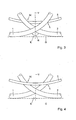
- Figs. 1-4 show an exemplary embodiment of a portable lightweight tent 10, with the tent in a folded-out, self-erected position of use.
- the tent 10 is provided with only three resilient frame elements 1, 2, 3 formed into endless loops.
- the frame elements 1,2,3 are provided with a tent covering 4 such that this covering 4 is stretched by the frame elements, with the tent 10 in the represented folded-out position of use.
- an inside space of the tent 10 can be completely closed off from an environment by the covering 4, at least such that ingress of, for instance, mosquitoes or other objects can be prevented.
- each frame element 1, 2, 3 can each be manufactured in different manners and from different materials, for instance from a suitable, resilient elastic synthetic, fibre-reinforced material, composite, carbon fibre, a suitable metal, alloy and/or the like.
- each frame element 1, 2, 3 is a substantially elliptical or circular element.
- Each frame element can for instance comprise an endless tube, rod or such element, hollow or not hollow, formed into a loop with a cross section that is, for instance, round or formed otherwise.
- the covering 4 of the tent 10 can also be designed in different manners, from different materials, for instance a suitable cloth of textile, plastic and/or the like.
- the covering 4 may be partly provided with an air transmissive structure, for instance a suitable gauze, mosquito net or the like.
- the covering 4 is provided with a closable entrance, window parts closed off by gauze and/or the like. Entrance parts and/or window parts of the covering 4 may be detachable by means of zippers, Velcro connections and/or the like.
- the covering may be provided with one of more covering layers, for instance with an inner tent covering and an outer tent covering.
- An entrance may for instance be located in a longitudinal side and/or upper side of the covering, at a distance from a head H and a foot F.
- the frame elements 1, 2, 3 and the covering 4 can be coupled to each other in different manners.
- the covering 4 may be provided with suitable passages, loops, recesses, connecting means, hemmed edges and/or the like, or be designed differently, for holding the frame elements 1, 2, 3.
- the frame elements 1, 2, 3 and the covering can be fixedly or detachably coupled to each other.
- the frame elements 1, 2, 3 can, for instance, be coupled together only via the covering 4, so that no special connecting means are to be used for coupling these elements 1, 2, 3 together.
- the tent 10 may be a baby tent or toddler tent, or a tent suitable for grown ups.
- the tent 10 can for instance have different sizes.
- the tent 10 is provided with a first frame element 1 and a second frame element 2, which cross at two positions adjacent the underside of the tent 10, on either side of the tent 10.
- the crossings are indicated with K.
- the tent underside bears, during use, on, for instance, an underground indicated by broken line G in Figs. 3 - 4 .
- the two crossings K are in or adjacent a vertical central transverse plane V of the tent 10, which plane V extends perpendicularly to the longitudinal direction of the tent 10.
- the crossings K are located at a relatively short distance above the underground G.
- the crossings K of the first and second frame element 1, 2 do not touch the underground G (see Figs. 3 and 4 ).
- the first and second frame element 1, 2, viewed in side view can include an angle ⁇ with each other at the crossing K mentioned which is smaller than 180°.
- both the first and the second frame element 1, 2 cross the central transverse plane V obliquely, at least not perpendicularly, viewed in side view.
- both the first and the second frame element 1, 2 are provided with an upper arch part 1T, 2T respectively, located, with the tent in erected position, at the tent upper side. Furthermore, both the first and the second frame element 1, 2 are provided with a lower arch part 1B, 2B, respectively, located, with the tent in erected position, at the underside of the tent 10.
- the two lower arch parts 1B, 2B of the first and second frame part 1, 2 face substantially away from each other, and can stretch a bottom B of the tent 10.
- a roof part T of the tent can be stretched between the two upper arch parts 1T, 2T of the first and second frame part 1, 2.
- the first and second frame element 1, 2 are folded out to form substantially bent ellipsoids with substantially the same form.
- the bent ellipsoids 1, 2 are substantially mirror symmetrical relative to the central transverse plane V mentioned.
- the tent is substantially mirror symmetrical relative to the central transverse plane V, as clearly follows from the drawing. It appears that in this manner, an equally balanced loading of the covering 4 can be obtained, which increases the durability of the tent.
- the exemplary embodiment is provided with a third frame element 3.
- Arch parts remote from each other of the third frame element 3 extend at positions between the tent upper side and tent lower side, at least with the tent in erected position.
- the arch parts remote from each other of the third frame element 3 extend at lower positions than the upper arch parts 1T, 2T of the first and second frame element 1, 2, with the tent in a position of use. Moreover, the arch parts remote from each other of the third frame part 3 are then located at higher positions than the lower arch parts 1B, 2B of the first and second frame element 1, 2.
- these arch parts remote from each other of the third frame element 3 extend, for instance, approximately at half the height of the tent 10, at least at the foot F and head H mentioned.
- the third frame element 3 is for instance also folded-out to form a substantially bent ellipsoid, with for instance virtually the same form as that of the first and second element 1, 2 in the respective folded-out position of use.
- the inside space of the tent 10, in particular the head H and the foot F, can be enlarged in a simple manner, and overload to the covering 4 can be prevented.
- the third frame element 3 is for instance somewhat saddle-shaped.
- the third frame element 3 may extend at a distance from the crossings K between the first and second frame element 1, 2 with the tent in erected position.
- the third frame element can cross the central transverse plane V for instance substantially at right angles, and runs, at that location, for instance substantially parallel to the underground G of the tent 10.
- the third frame element 3 can, for instance, form two crossings L with the first frame element, and two crossings M with the second frame element 2.
- the third frame element 3 may cross the crossings K between the first and second frame element 1, 2 or reach therealong.
- the three frame elements 1, 2, 3 are designed such that they can produce a particular spring force on the tent covering 4 with the tent in erected position. It is, for instance, advantageous when the frame elements 1, 2, 3 each independently would bend or relax into a substantially flat elliptical or circular starting position, if the frame elements 1, 2, 3 were not provided with the tent covering 4 and were, for instance, released.
- a flat starting position in itself elliptical, is represented in Figs. 4 and 5 . It appears that the elliptical starting position is advantageous in particular with a relatively low tent.
- such a relaxation of the frame elements 1, 2, 3 is then counteracted by the tent covering 4, which may lead to the covering being stretched relatively tautly.
- the three frame elements 1, 2, 3 form springs that can automatically bring the covering 4 to the folded-out position of use, and can keep it at a relatively uniformly distributed tension.
- the third frame element 3 can then simply effect that, both adjacent the head H and foot F, the tent wall/covering proceeds upwards in a relatively straight manner, or includes only a small angle with a vertical plane, so as to provide more head/foot space in the tent 10.
- the third frame element 3 further provides additional stability to the tent 10.
- the tent can simply be brought from the erected position shown in Figs. 1 and 2 to a collapsed position, and vice versa.
- the tent 10 is preferably substantially circular or disc-shaped. Collapsing the tent 10 may be carried out in a manner corresponding to that as described in Figs. 8.- 15 of US 4,858,634 , which Figures are understood to be incorporated in the present application by reference.
- the head H and foot F of the tent 10 are first folded together, while the bottom parts 1B, 2B of the frame elements 1, 2 are moved towards each other.
- the thus collapsed structure can be rotated through 90° and be placed on an underground to then be collapsed further to form a circular or disc-shaped structure.
- the collapsed tent can for instance be fixed in that position and/or be stored.
- the tent 10 represented in the Figures is relatively stable and durable, and lightweight. Furthermore, the tent 10 can be designed in relatively few parts.
- a bottom of the tent can for instance be integrally provided with a mattress, or with a bag or recess in which a mattress can be placed.
- the tent can for instance be provided with a double bottom, for instance a bottom with two cloth layers provided one on top of the other which can bound a space in which a mattress can be included.
Landscapes
- Engineering & Computer Science (AREA)
- Architecture (AREA)
- Civil Engineering (AREA)
- Structural Engineering (AREA)
- Tents Or Canopies (AREA)
- Diaphragms For Electromechanical Transducers (AREA)
- Polymerisation Methods In General (AREA)
Priority Applications (1)
| Application Number | Priority Date | Filing Date | Title |
|---|---|---|---|
| PL06747577T PL1907653T3 (pl) | 2005-06-29 | 2006-06-27 | Samo-rozkładający się namiot |
Applications Claiming Priority (2)
| Application Number | Priority Date | Filing Date | Title |
|---|---|---|---|
| NL1029365A NL1029365C2 (nl) | 2005-06-29 | 2005-06-29 | Een zichzelf oprichtende tent. |
| PCT/NL2006/000317 WO2007001171A1 (en) | 2005-06-29 | 2006-06-27 | A self-erecting tent |
Publications (2)
| Publication Number | Publication Date |
|---|---|
| EP1907653A1 EP1907653A1 (en) | 2008-04-09 |
| EP1907653B1 true EP1907653B1 (en) | 2011-01-26 |
Family
ID=35892279
Family Applications (1)
| Application Number | Title | Priority Date | Filing Date |
|---|---|---|---|
| EP06747577A Active EP1907653B1 (en) | 2005-06-29 | 2006-06-27 | A self-erecting tent |
Country Status (10)
| Country | Link |
|---|---|
| US (2) | US8096311B2 (pl) |
| EP (1) | EP1907653B1 (pl) |
| AT (1) | ATE497074T1 (pl) |
| AU (1) | AU2006262977B2 (pl) |
| DE (1) | DE602006019874D1 (pl) |
| DK (1) | DK1907653T3 (pl) |
| ES (1) | ES2359802T3 (pl) |
| NL (1) | NL1029365C2 (pl) |
| PL (1) | PL1907653T3 (pl) |
| WO (1) | WO2007001171A1 (pl) |
Families Citing this family (12)
| Publication number | Priority date | Publication date | Assignee | Title |
|---|---|---|---|---|
| GB2451651B (en) * | 2007-08-04 | 2012-02-01 | Finecard Internat Ltd | Pop up structure, primarily for use as a travel cot |
| US8567424B2 (en) | 2010-07-23 | 2013-10-29 | Gregory P. Hill, Sr. | Tent and tent frame |
| US8651124B2 (en) | 2010-11-23 | 2014-02-18 | Nage Colin Damas | Tent with dividable mattress pocket |
| US20130276847A1 (en) * | 2012-04-18 | 2013-10-24 | Thomas J. Vulich | Moisture and heat management system |
| US10047457B2 (en) * | 2013-09-16 | 2018-08-14 | Applied Materials, Inc. | EPI pre-heat ring |
| US9695586B1 (en) | 2015-05-18 | 2017-07-04 | National Technology & Engineering Solutions Of Sandia, Llc | Self-erecting shapes |
| USD802226S1 (en) * | 2016-05-20 | 2017-11-07 | Robert Caputo | Pet enclosure |
| USD763391S1 (en) | 2016-05-31 | 2016-08-09 | Zhifeng Xu | Foldable tent |
| USD778383S1 (en) | 2016-09-08 | 2017-02-07 | Zhifeng Xu | Foldable tent |
| USD929136S1 (en) * | 2019-05-13 | 2021-08-31 | Packinlight LLC | Compact playpen |
| US20220110302A1 (en) * | 2020-10-09 | 2022-04-14 | Yunior Dominguez | Collapsible bait net |
| US20230304317A1 (en) * | 2022-03-23 | 2023-09-28 | Lun Xu | Collapsible Tent Structures |
Family Cites Families (13)
| Publication number | Priority date | Publication date | Assignee | Title |
|---|---|---|---|---|
| US2907056A (en) * | 1957-10-03 | 1959-10-06 | Kaplan Julius | Sleeping-bag-tent construction |
| US4590956A (en) * | 1984-04-27 | 1986-05-27 | Harrell Griesenbeck | Bed tent |
| US4858634A (en) | 1988-07-18 | 1989-08-22 | Mcleese Eddie S | Self erecting structure |
| US5163461A (en) | 1991-10-17 | 1992-11-17 | Ivanovich Michael K | Self-erecting shelter |
| US5337772A (en) * | 1993-04-12 | 1994-08-16 | Habchi Elie E | Self-unfolding shelter |
| US5396917A (en) * | 1994-02-03 | 1995-03-14 | Hazinski; Daniel P. | Self erecting high top tent |
| US5636478A (en) * | 1995-04-13 | 1997-06-10 | Jhy Yih Electric Enterprise Co., Ltd | Inflatable tent structure |
| US5642538A (en) * | 1995-09-18 | 1997-07-01 | Creative Toy Products, Inc. | Self-erecting play yard structure |
| US5601105A (en) * | 1996-04-08 | 1997-02-11 | Blen; Charles A. | Self-erecting tent |
| US6672323B2 (en) * | 1998-10-15 | 2004-01-06 | The United States Of America As Represented By The Secretary Of The Army | Multi-purpose self-erecting structure having advanced insect protection and storage characteristics |
| KR19990021900U (ko) | 1999-01-21 | 1999-06-25 | 송국정 | 물에뜨는텐트 |
| US6952844B2 (en) * | 2003-08-27 | 2005-10-11 | Danaher Thomas C | Bed-tent |
| FR2877966B1 (fr) * | 2004-11-17 | 2007-01-12 | Promiles Sa | Tente auto-deployable comprenant une chambre interieure |
-
2005
- 2005-06-29 NL NL1029365A patent/NL1029365C2/nl not_active IP Right Cessation
-
2006
- 2006-06-27 EP EP06747577A patent/EP1907653B1/en active Active
- 2006-06-27 AU AU2006262977A patent/AU2006262977B2/en active Active
- 2006-06-27 DK DK06747577.2T patent/DK1907653T3/da active
- 2006-06-27 WO PCT/NL2006/000317 patent/WO2007001171A1/en not_active Ceased
- 2006-06-27 ES ES06747577T patent/ES2359802T3/es active Active
- 2006-06-27 AT AT06747577T patent/ATE497074T1/de not_active IP Right Cessation
- 2006-06-27 DE DE602006019874T patent/DE602006019874D1/de active Active
- 2006-06-27 PL PL06747577T patent/PL1907653T3/pl unknown
- 2006-06-27 US US11/993,437 patent/US8096311B2/en active Active
-
2012
- 2012-01-13 US US13/350,349 patent/US8387643B2/en active Active
Also Published As
| Publication number | Publication date |
|---|---|
| DE602006019874D1 (de) | 2011-03-10 |
| PL1907653T3 (pl) | 2011-07-29 |
| EP1907653A1 (en) | 2008-04-09 |
| DK1907653T3 (da) | 2011-05-16 |
| WO2007001171A1 (en) | 2007-01-04 |
| AU2006262977B2 (en) | 2012-02-16 |
| ES2359802T3 (es) | 2011-05-27 |
| US20120160287A1 (en) | 2012-06-28 |
| ATE497074T1 (de) | 2011-02-15 |
| US8387643B2 (en) | 2013-03-05 |
| AU2006262977A1 (en) | 2007-01-04 |
| US8096311B2 (en) | 2012-01-17 |
| NL1029365C2 (nl) | 2007-01-02 |
| US20100101618A1 (en) | 2010-04-29 |
Similar Documents
| Publication | Publication Date | Title |
|---|---|---|
| US8387643B2 (en) | Self-erecting tent | |
| US9162127B2 (en) | Goal apparatus | |
| US6363955B1 (en) | Self-deploying tubular enclosure | |
| US8087423B2 (en) | Apparatus for providing protection against the sun | |
| US6926020B2 (en) | Vertically stacked collapsible structures | |
| US6098349A (en) | Collapsible structures | |
| US3165760A (en) | Infant's crib | |
| EP1094177B1 (en) | Collapsible fabric with coilable supports structures | |
| US6848460B2 (en) | Collapsible sleeping structures | |
| US9463367B2 (en) | Goal apparatus | |
| US9480894B2 (en) | Goal apparatus | |
| US4537210A (en) | Shelter | |
| US20040140232A1 (en) | Collapsible structures | |
| US20090212050A1 (en) | Collapsible structures with liners | |
| US8684020B1 (en) | Modified A-frame tent shelter | |
| WO2001037951A1 (en) | Portable net device | |
| US20210115694A1 (en) | Self-opening and collapsible tent structure | |
| WO1998051890A1 (en) | Pyramidal tent-like structure | |
| GB2410262A (en) | Igloo/dome tent | |
| US20040065361A1 (en) | Foldable bed tent | |
| CA2458845C (en) | Pop up collapsible structures | |
| US20230304317A1 (en) | Collapsible Tent Structures | |
| US20090025767A1 (en) | Collapsible structures |
Legal Events
| Date | Code | Title | Description |
|---|---|---|---|
| PUAI | Public reference made under article 153(3) epc to a published international application that has entered the european phase |
Free format text: ORIGINAL CODE: 0009012 |
|
| 17P | Request for examination filed |
Effective date: 20080128 |
|
| AK | Designated contracting states |
Kind code of ref document: A1 Designated state(s): AT BE BG CH CY CZ DE DK EE ES FI FR GB GR HU IE IS IT LI LT LU LV MC NL PL PT RO SE SI SK TR |
|
| 17Q | First examination report despatched |
Effective date: 20080515 |
|
| DAX | Request for extension of the european patent (deleted) | ||
| GRAP | Despatch of communication of intention to grant a patent |
Free format text: ORIGINAL CODE: EPIDOSNIGR1 |
|
| GRAS | Grant fee paid |
Free format text: ORIGINAL CODE: EPIDOSNIGR3 |
|
| GRAA | (expected) grant |
Free format text: ORIGINAL CODE: 0009210 |
|
| AK | Designated contracting states |
Kind code of ref document: B1 Designated state(s): AT BE BG CH CY CZ DE DK EE ES FI FR GB GR HU IE IS IT LI LT LU LV MC NL PL PT RO SE SI SK TR |
|
| REG | Reference to a national code |
Ref country code: GB Ref legal event code: FG4D |
|
| REG | Reference to a national code |
Ref country code: CH Ref legal event code: EP |
|
| REG | Reference to a national code |
Ref country code: IE Ref legal event code: FG4D |
|
| REF | Corresponds to: |
Ref document number: 602006019874 Country of ref document: DE Date of ref document: 20110310 Kind code of ref document: P |
|
| REG | Reference to a national code |
Ref country code: DE Ref legal event code: R096 Ref document number: 602006019874 Country of ref document: DE Effective date: 20110310 |
|
| REG | Reference to a national code |
Ref country code: CH Ref legal event code: NV Representative=s name: BOVARD AG |
|
| REG | Reference to a national code |
Ref country code: NL Ref legal event code: T3 |
|
| REG | Reference to a national code |
Ref country code: DK Ref legal event code: T3 |
|
| REG | Reference to a national code |
Ref country code: ES Ref legal event code: FG2A Ref document number: 2359802 Country of ref document: ES Kind code of ref document: T3 Effective date: 20110527 |
|
| LTIE | Lt: invalidation of european patent or patent extension |
Effective date: 20110126 |
|
| PG25 | Lapsed in a contracting state [announced via postgrant information from national office to epo] |
Ref country code: GR Free format text: LAPSE BECAUSE OF FAILURE TO SUBMIT A TRANSLATION OF THE DESCRIPTION OR TO PAY THE FEE WITHIN THE PRESCRIBED TIME-LIMIT Effective date: 20110427 Ref country code: SE Free format text: LAPSE BECAUSE OF FAILURE TO SUBMIT A TRANSLATION OF THE DESCRIPTION OR TO PAY THE FEE WITHIN THE PRESCRIBED TIME-LIMIT Effective date: 20110126 Ref country code: LT Free format text: LAPSE BECAUSE OF FAILURE TO SUBMIT A TRANSLATION OF THE DESCRIPTION OR TO PAY THE FEE WITHIN THE PRESCRIBED TIME-LIMIT Effective date: 20110126 Ref country code: IS Free format text: LAPSE BECAUSE OF FAILURE TO SUBMIT A TRANSLATION OF THE DESCRIPTION OR TO PAY THE FEE WITHIN THE PRESCRIBED TIME-LIMIT Effective date: 20110526 Ref country code: PT Free format text: LAPSE BECAUSE OF FAILURE TO SUBMIT A TRANSLATION OF THE DESCRIPTION OR TO PAY THE FEE WITHIN THE PRESCRIBED TIME-LIMIT Effective date: 20110526 Ref country code: LV Free format text: LAPSE BECAUSE OF FAILURE TO SUBMIT A TRANSLATION OF THE DESCRIPTION OR TO PAY THE FEE WITHIN THE PRESCRIBED TIME-LIMIT Effective date: 20110126 |
|
| REG | Reference to a national code |
Ref country code: PL Ref legal event code: T3 |
|
| PG25 | Lapsed in a contracting state [announced via postgrant information from national office to epo] |
Ref country code: BG Free format text: LAPSE BECAUSE OF FAILURE TO SUBMIT A TRANSLATION OF THE DESCRIPTION OR TO PAY THE FEE WITHIN THE PRESCRIBED TIME-LIMIT Effective date: 20110426 Ref country code: SI Free format text: LAPSE BECAUSE OF FAILURE TO SUBMIT A TRANSLATION OF THE DESCRIPTION OR TO PAY THE FEE WITHIN THE PRESCRIBED TIME-LIMIT Effective date: 20110126 Ref country code: CY Free format text: LAPSE BECAUSE OF FAILURE TO SUBMIT A TRANSLATION OF THE DESCRIPTION OR TO PAY THE FEE WITHIN THE PRESCRIBED TIME-LIMIT Effective date: 20110126 Ref country code: AT Free format text: LAPSE BECAUSE OF FAILURE TO SUBMIT A TRANSLATION OF THE DESCRIPTION OR TO PAY THE FEE WITHIN THE PRESCRIBED TIME-LIMIT Effective date: 20110126 Ref country code: FI Free format text: LAPSE BECAUSE OF FAILURE TO SUBMIT A TRANSLATION OF THE DESCRIPTION OR TO PAY THE FEE WITHIN THE PRESCRIBED TIME-LIMIT Effective date: 20110126 Ref country code: BE Free format text: LAPSE BECAUSE OF FAILURE TO SUBMIT A TRANSLATION OF THE DESCRIPTION OR TO PAY THE FEE WITHIN THE PRESCRIBED TIME-LIMIT Effective date: 20110126 |
|
| REG | Reference to a national code |
Ref country code: HU Ref legal event code: AG4A Ref document number: E011143 Country of ref document: HU |
|
| PG25 | Lapsed in a contracting state [announced via postgrant information from national office to epo] |
Ref country code: EE Free format text: LAPSE BECAUSE OF FAILURE TO SUBMIT A TRANSLATION OF THE DESCRIPTION OR TO PAY THE FEE WITHIN THE PRESCRIBED TIME-LIMIT Effective date: 20110126 |
|
| PG25 | Lapsed in a contracting state [announced via postgrant information from national office to epo] |
Ref country code: SK Free format text: LAPSE BECAUSE OF FAILURE TO SUBMIT A TRANSLATION OF THE DESCRIPTION OR TO PAY THE FEE WITHIN THE PRESCRIBED TIME-LIMIT Effective date: 20110126 Ref country code: CZ Free format text: LAPSE BECAUSE OF FAILURE TO SUBMIT A TRANSLATION OF THE DESCRIPTION OR TO PAY THE FEE WITHIN THE PRESCRIBED TIME-LIMIT Effective date: 20110126 Ref country code: RO Free format text: LAPSE BECAUSE OF FAILURE TO SUBMIT A TRANSLATION OF THE DESCRIPTION OR TO PAY THE FEE WITHIN THE PRESCRIBED TIME-LIMIT Effective date: 20110126 |
|
| PLBE | No opposition filed within time limit |
Free format text: ORIGINAL CODE: 0009261 |
|
| STAA | Information on the status of an ep patent application or granted ep patent |
Free format text: STATUS: NO OPPOSITION FILED WITHIN TIME LIMIT |
|
| 26N | No opposition filed |
Effective date: 20111027 |
|
| REG | Reference to a national code |
Ref country code: DE Ref legal event code: R097 Ref document number: 602006019874 Country of ref document: DE Effective date: 20111027 |
|
| REG | Reference to a national code |
Ref country code: IE Ref legal event code: MM4A |
|
| PG25 | Lapsed in a contracting state [announced via postgrant information from national office to epo] |
Ref country code: IE Free format text: LAPSE BECAUSE OF NON-PAYMENT OF DUE FEES Effective date: 20110627 |
|
| PG25 | Lapsed in a contracting state [announced via postgrant information from national office to epo] |
Ref country code: MC Free format text: LAPSE BECAUSE OF NON-PAYMENT OF DUE FEES Effective date: 20110630 |
|
| PG25 | Lapsed in a contracting state [announced via postgrant information from national office to epo] |
Ref country code: LU Free format text: LAPSE BECAUSE OF NON-PAYMENT OF DUE FEES Effective date: 20110627 |
|
| PG25 | Lapsed in a contracting state [announced via postgrant information from national office to epo] |
Ref country code: PL Free format text: LAPSE BECAUSE OF NON-PAYMENT OF DUE FEES Effective date: 20120627 |
|
| PG25 | Lapsed in a contracting state [announced via postgrant information from national office to epo] |
Ref country code: TR Free format text: LAPSE BECAUSE OF FAILURE TO SUBMIT A TRANSLATION OF THE DESCRIPTION OR TO PAY THE FEE WITHIN THE PRESCRIBED TIME-LIMIT Effective date: 20110126 |
|
| REG | Reference to a national code |
Ref country code: PL Ref legal event code: LAPE |
|
| PGFP | Annual fee paid to national office [announced via postgrant information from national office to epo] |
Ref country code: CH Payment date: 20150618 Year of fee payment: 10 Ref country code: ES Payment date: 20150626 Year of fee payment: 10 |
|
| PGFP | Annual fee paid to national office [announced via postgrant information from national office to epo] |
Ref country code: HU Payment date: 20150618 Year of fee payment: 10 |
|
| REG | Reference to a national code |
Ref country code: FR Ref legal event code: PLFP Year of fee payment: 11 |
|
| REG | Reference to a national code |
Ref country code: CH Ref legal event code: PL |
|
| PG25 | Lapsed in a contracting state [announced via postgrant information from national office to epo] |
Ref country code: HU Free format text: LAPSE BECAUSE OF NON-PAYMENT OF DUE FEES Effective date: 20160628 Ref country code: CH Free format text: LAPSE BECAUSE OF NON-PAYMENT OF DUE FEES Effective date: 20160630 Ref country code: LI Free format text: LAPSE BECAUSE OF NON-PAYMENT OF DUE FEES Effective date: 20160630 |
|
| REG | Reference to a national code |
Ref country code: FR Ref legal event code: PLFP Year of fee payment: 12 |
|
| PG25 | Lapsed in a contracting state [announced via postgrant information from national office to epo] |
Ref country code: ES Free format text: LAPSE BECAUSE OF NON-PAYMENT OF DUE FEES Effective date: 20160628 |
|
| REG | Reference to a national code |
Ref country code: FR Ref legal event code: PLFP Year of fee payment: 13 |
|
| REG | Reference to a national code |
Ref country code: ES Ref legal event code: FD2A Effective date: 20181204 |
|
| P01 | Opt-out of the competence of the unified patent court (upc) registered |
Effective date: 20230522 |
|
| PGFP | Annual fee paid to national office [announced via postgrant information from national office to epo] |
Ref country code: DE Payment date: 20250618 Year of fee payment: 20 |
|
| PGFP | Annual fee paid to national office [announced via postgrant information from national office to epo] |
Ref country code: GB Payment date: 20250618 Year of fee payment: 20 Ref country code: DK Payment date: 20250625 Year of fee payment: 20 |
|
| PGFP | Annual fee paid to national office [announced via postgrant information from national office to epo] |
Ref country code: NL Payment date: 20250618 Year of fee payment: 20 |
|
| PGFP | Annual fee paid to national office [announced via postgrant information from national office to epo] |
Ref country code: FR Payment date: 20250620 Year of fee payment: 20 |
|
| PGFP | Annual fee paid to national office [announced via postgrant information from national office to epo] |
Ref country code: IT Payment date: 20250624 Year of fee payment: 20 |