EP1906878B1 - Branch vessel stent graft - Google Patents
Branch vessel stent graft Download PDFInfo
- Publication number
- EP1906878B1 EP1906878B1 EP06774523.2A EP06774523A EP1906878B1 EP 1906878 B1 EP1906878 B1 EP 1906878B1 EP 06774523 A EP06774523 A EP 06774523A EP 1906878 B1 EP1906878 B1 EP 1906878B1
- Authority
- EP
- European Patent Office
- Prior art keywords
- extension piece
- stent graft
- side arm
- tubular body
- stent
- Prior art date
- Legal status (The legal status is an assumption and is not a legal conclusion. Google has not performed a legal analysis and makes no representation as to the accuracy of the status listed.)
- Active
Links
- 230000002787 reinforcement Effects 0.000 claims description 9
- 239000003550 marker Substances 0.000 claims description 7
- 239000000463 material Substances 0.000 claims description 6
- HLXZNVUGXRDIFK-UHFFFAOYSA-N nickel titanium Chemical compound [Ti].[Ti].[Ti].[Ti].[Ti].[Ti].[Ti].[Ti].[Ti].[Ti].[Ti].[Ni].[Ni].[Ni].[Ni].[Ni].[Ni].[Ni].[Ni].[Ni].[Ni].[Ni].[Ni].[Ni].[Ni] HLXZNVUGXRDIFK-UHFFFAOYSA-N 0.000 claims description 6
- 229910001000 nickel titanium Inorganic materials 0.000 claims description 6
- 229920000642 polymer Polymers 0.000 claims description 5
- 239000004810 polytetrafluoroethylene Substances 0.000 claims description 5
- 229920001343 polytetrafluoroethylene Polymers 0.000 claims description 5
- 229920004934 Dacron® Polymers 0.000 claims description 4
- 239000005020 polyethylene terephthalate Substances 0.000 claims description 4
- 239000000560 biocompatible material Substances 0.000 claims description 3
- 239000012530 fluid Substances 0.000 claims description 2
- 238000000034 method Methods 0.000 description 10
- 210000005166 vasculature Anatomy 0.000 description 6
- 210000000709 aorta Anatomy 0.000 description 5
- 210000003090 iliac artery Anatomy 0.000 description 4
- 238000012800 visualization Methods 0.000 description 4
- 230000003014 reinforcing effect Effects 0.000 description 3
- 208000001750 Endoleak Diseases 0.000 description 2
- 241001465754 Metazoa Species 0.000 description 2
- 239000000853 adhesive Substances 0.000 description 2
- 230000001070 adhesive effect Effects 0.000 description 2
- 230000017531 blood circulation Effects 0.000 description 2
- KPUWHANPEXNPJT-UHFFFAOYSA-N disiloxane Chemical class [SiH3]O[SiH3] KPUWHANPEXNPJT-UHFFFAOYSA-N 0.000 description 2
- 239000013536 elastomeric material Substances 0.000 description 2
- 229910001220 stainless steel Inorganic materials 0.000 description 2
- 239000010935 stainless steel Substances 0.000 description 2
- 206010002329 Aneurysm Diseases 0.000 description 1
- 102000009123 Fibrin Human genes 0.000 description 1
- 108010073385 Fibrin Proteins 0.000 description 1
- BWGVNKXGVNDBDI-UHFFFAOYSA-N Fibrin monomer Chemical compound CNC(=O)CNC(=O)CN BWGVNKXGVNDBDI-UHFFFAOYSA-N 0.000 description 1
- 239000003795 chemical substances by application Substances 0.000 description 1
- 201000010099 disease Diseases 0.000 description 1
- 208000037265 diseases, disorders, signs and symptoms Diseases 0.000 description 1
- 229920001971 elastomer Polymers 0.000 description 1
- 239000000806 elastomer Substances 0.000 description 1
- 238000005516 engineering process Methods 0.000 description 1
- 229950003499 fibrin Drugs 0.000 description 1
- PCHJSUWPFVWCPO-UHFFFAOYSA-N gold Chemical compound [Au] PCHJSUWPFVWCPO-UHFFFAOYSA-N 0.000 description 1
- 239000010931 gold Substances 0.000 description 1
- 229910052737 gold Inorganic materials 0.000 description 1
- 238000004519 manufacturing process Methods 0.000 description 1
- 229920002635 polyurethane Polymers 0.000 description 1
- 239000004814 polyurethane Substances 0.000 description 1
- 102000004169 proteins and genes Human genes 0.000 description 1
- 108090000623 proteins and genes Proteins 0.000 description 1
- 238000002601 radiography Methods 0.000 description 1
- 238000007789 sealing Methods 0.000 description 1
- 239000003356 suture material Substances 0.000 description 1
Images

Classifications
-
- A—HUMAN NECESSITIES
- A61—MEDICAL OR VETERINARY SCIENCE; HYGIENE
- A61F—FILTERS IMPLANTABLE INTO BLOOD VESSELS; PROSTHESES; DEVICES PROVIDING PATENCY TO, OR PREVENTING COLLAPSING OF, TUBULAR STRUCTURES OF THE BODY, e.g. STENTS; ORTHOPAEDIC, NURSING OR CONTRACEPTIVE DEVICES; FOMENTATION; TREATMENT OR PROTECTION OF EYES OR EARS; BANDAGES, DRESSINGS OR ABSORBENT PADS; FIRST-AID KITS
- A61F2/00—Filters implantable into blood vessels; Prostheses, i.e. artificial substitutes or replacements for parts of the body; Appliances for connecting them with the body; Devices providing patency to, or preventing collapsing of, tubular structures of the body, e.g. stents
- A61F2/02—Prostheses implantable into the body
- A61F2/04—Hollow or tubular parts of organs, e.g. bladders, tracheae, bronchi or bile ducts
- A61F2/06—Blood vessels
- A61F2/07—Stent-grafts
-
- A—HUMAN NECESSITIES
- A61—MEDICAL OR VETERINARY SCIENCE; HYGIENE
- A61F—FILTERS IMPLANTABLE INTO BLOOD VESSELS; PROSTHESES; DEVICES PROVIDING PATENCY TO, OR PREVENTING COLLAPSING OF, TUBULAR STRUCTURES OF THE BODY, e.g. STENTS; ORTHOPAEDIC, NURSING OR CONTRACEPTIVE DEVICES; FOMENTATION; TREATMENT OR PROTECTION OF EYES OR EARS; BANDAGES, DRESSINGS OR ABSORBENT PADS; FIRST-AID KITS
- A61F2/00—Filters implantable into blood vessels; Prostheses, i.e. artificial substitutes or replacements for parts of the body; Appliances for connecting them with the body; Devices providing patency to, or preventing collapsing of, tubular structures of the body, e.g. stents
- A61F2/82—Devices providing patency to, or preventing collapsing of, tubular structures of the body, e.g. stents
- A61F2/86—Stents in a form characterised by the wire-like elements; Stents in the form characterised by a net-like or mesh-like structure
- A61F2/89—Stents in a form characterised by the wire-like elements; Stents in the form characterised by a net-like or mesh-like structure the wire-like elements comprising two or more adjacent rings flexibly connected by separate members
-
- A—HUMAN NECESSITIES
- A61—MEDICAL OR VETERINARY SCIENCE; HYGIENE
- A61F—FILTERS IMPLANTABLE INTO BLOOD VESSELS; PROSTHESES; DEVICES PROVIDING PATENCY TO, OR PREVENTING COLLAPSING OF, TUBULAR STRUCTURES OF THE BODY, e.g. STENTS; ORTHOPAEDIC, NURSING OR CONTRACEPTIVE DEVICES; FOMENTATION; TREATMENT OR PROTECTION OF EYES OR EARS; BANDAGES, DRESSINGS OR ABSORBENT PADS; FIRST-AID KITS
- A61F2/00—Filters implantable into blood vessels; Prostheses, i.e. artificial substitutes or replacements for parts of the body; Appliances for connecting them with the body; Devices providing patency to, or preventing collapsing of, tubular structures of the body, e.g. stents
- A61F2/02—Prostheses implantable into the body
- A61F2/04—Hollow or tubular parts of organs, e.g. bladders, tracheae, bronchi or bile ducts
- A61F2/06—Blood vessels
- A61F2002/065—Y-shaped blood vessels
- A61F2002/067—Y-shaped blood vessels modular
-
- A—HUMAN NECESSITIES
- A61—MEDICAL OR VETERINARY SCIENCE; HYGIENE
- A61F—FILTERS IMPLANTABLE INTO BLOOD VESSELS; PROSTHESES; DEVICES PROVIDING PATENCY TO, OR PREVENTING COLLAPSING OF, TUBULAR STRUCTURES OF THE BODY, e.g. STENTS; ORTHOPAEDIC, NURSING OR CONTRACEPTIVE DEVICES; FOMENTATION; TREATMENT OR PROTECTION OF EYES OR EARS; BANDAGES, DRESSINGS OR ABSORBENT PADS; FIRST-AID KITS
- A61F2/00—Filters implantable into blood vessels; Prostheses, i.e. artificial substitutes or replacements for parts of the body; Appliances for connecting them with the body; Devices providing patency to, or preventing collapsing of, tubular structures of the body, e.g. stents
- A61F2/02—Prostheses implantable into the body
- A61F2/04—Hollow or tubular parts of organs, e.g. bladders, tracheae, bronchi or bile ducts
- A61F2/06—Blood vessels
- A61F2/07—Stent-grafts
- A61F2002/075—Stent-grafts the stent being loosely attached to the graft material, e.g. by stitching
-
- A—HUMAN NECESSITIES
- A61—MEDICAL OR VETERINARY SCIENCE; HYGIENE
- A61F—FILTERS IMPLANTABLE INTO BLOOD VESSELS; PROSTHESES; DEVICES PROVIDING PATENCY TO, OR PREVENTING COLLAPSING OF, TUBULAR STRUCTURES OF THE BODY, e.g. STENTS; ORTHOPAEDIC, NURSING OR CONTRACEPTIVE DEVICES; FOMENTATION; TREATMENT OR PROTECTION OF EYES OR EARS; BANDAGES, DRESSINGS OR ABSORBENT PADS; FIRST-AID KITS
- A61F2220/00—Fixations or connections for prostheses classified in groups A61F2/00 - A61F2/26 or A61F2/82 or A61F9/00 or A61F11/00 or subgroups thereof
- A61F2220/0025—Connections or couplings between prosthetic parts, e.g. between modular parts; Connecting elements
- A61F2220/005—Connections or couplings between prosthetic parts, e.g. between modular parts; Connecting elements using adhesives
-
- A—HUMAN NECESSITIES
- A61—MEDICAL OR VETERINARY SCIENCE; HYGIENE
- A61F—FILTERS IMPLANTABLE INTO BLOOD VESSELS; PROSTHESES; DEVICES PROVIDING PATENCY TO, OR PREVENTING COLLAPSING OF, TUBULAR STRUCTURES OF THE BODY, e.g. STENTS; ORTHOPAEDIC, NURSING OR CONTRACEPTIVE DEVICES; FOMENTATION; TREATMENT OR PROTECTION OF EYES OR EARS; BANDAGES, DRESSINGS OR ABSORBENT PADS; FIRST-AID KITS
- A61F2220/00—Fixations or connections for prostheses classified in groups A61F2/00 - A61F2/26 or A61F2/82 or A61F9/00 or A61F11/00 or subgroups thereof
- A61F2220/0025—Connections or couplings between prosthetic parts, e.g. between modular parts; Connecting elements
- A61F2220/0075—Connections or couplings between prosthetic parts, e.g. between modular parts; Connecting elements sutured, ligatured or stitched, retained or tied with a rope, string, thread, wire or cable
-
- A—HUMAN NECESSITIES
- A61—MEDICAL OR VETERINARY SCIENCE; HYGIENE
- A61F—FILTERS IMPLANTABLE INTO BLOOD VESSELS; PROSTHESES; DEVICES PROVIDING PATENCY TO, OR PREVENTING COLLAPSING OF, TUBULAR STRUCTURES OF THE BODY, e.g. STENTS; ORTHOPAEDIC, NURSING OR CONTRACEPTIVE DEVICES; FOMENTATION; TREATMENT OR PROTECTION OF EYES OR EARS; BANDAGES, DRESSINGS OR ABSORBENT PADS; FIRST-AID KITS
- A61F2230/00—Geometry of prostheses classified in groups A61F2/00 - A61F2/26 or A61F2/82 or A61F9/00 or A61F11/00 or subgroups thereof
- A61F2230/0002—Two-dimensional shapes, e.g. cross-sections
- A61F2230/0028—Shapes in the form of latin or greek characters
- A61F2230/005—Rosette-shaped, e.g. star-shaped
-
- A—HUMAN NECESSITIES
- A61—MEDICAL OR VETERINARY SCIENCE; HYGIENE
- A61F—FILTERS IMPLANTABLE INTO BLOOD VESSELS; PROSTHESES; DEVICES PROVIDING PATENCY TO, OR PREVENTING COLLAPSING OF, TUBULAR STRUCTURES OF THE BODY, e.g. STENTS; ORTHOPAEDIC, NURSING OR CONTRACEPTIVE DEVICES; FOMENTATION; TREATMENT OR PROTECTION OF EYES OR EARS; BANDAGES, DRESSINGS OR ABSORBENT PADS; FIRST-AID KITS
- A61F2230/00—Geometry of prostheses classified in groups A61F2/00 - A61F2/26 or A61F2/82 or A61F9/00 or A61F11/00 or subgroups thereof
- A61F2230/0002—Two-dimensional shapes, e.g. cross-sections
- A61F2230/0028—Shapes in the form of latin or greek characters
- A61F2230/0054—V-shaped
-
- A—HUMAN NECESSITIES
- A61—MEDICAL OR VETERINARY SCIENCE; HYGIENE
- A61F—FILTERS IMPLANTABLE INTO BLOOD VESSELS; PROSTHESES; DEVICES PROVIDING PATENCY TO, OR PREVENTING COLLAPSING OF, TUBULAR STRUCTURES OF THE BODY, e.g. STENTS; ORTHOPAEDIC, NURSING OR CONTRACEPTIVE DEVICES; FOMENTATION; TREATMENT OR PROTECTION OF EYES OR EARS; BANDAGES, DRESSINGS OR ABSORBENT PADS; FIRST-AID KITS
- A61F2230/00—Geometry of prostheses classified in groups A61F2/00 - A61F2/26 or A61F2/82 or A61F9/00 or A61F11/00 or subgroups thereof
- A61F2230/0063—Three-dimensional shapes
- A61F2230/0067—Three-dimensional shapes conical
Definitions
- This invention relates to a medical device and more particularly to a medical device for endovascular deployment into a body lumen such as the vasculature of an animal or human.
- branch vessel stent grafts deployed into vasculature of a human or animal to provide an alternate flow path where the vasculature has been damaged by accident or disease.
- the branch vessel stent graft allows an extension piece to be deployed from a main graft into a side vessel of the vasculature so that blood flow can enter the side vessel.
- the conventional procedure to treat branch vessels utilizes a balloon expandable covered stentwhich is deployed through the side arm ofthe stent graft to connect the side vessels to a bifurcated stent graft.
- the limitation of a delivery system for such balloon expandable covered stents is normally 7 to 8 French which makes the design of the stent graft deployment system challenging.
- a further challenge is then providing a sufficient attachment between the branch vessel stent graft and the side arm ofthe main graft since endoleaks can occur and these are of significant concern.
- a stent graft according to the preamble of claim 1 is known from the document US-A-2004/0082990 .
- distal with respect to a portion of the aorta, a deployment device or a prosthesis is the end of the aorta, deployment device or prosthesis further away in the direction of blood flow away from the heart and the term proximal means the portion of the aorta, deployment device or end of the prosthesis nearer to the heart.
- proximal means the portion of the aorta, deployment device or end of the prosthesis nearer to the heart.
- a stent graft as specified in claim 1.
- tubular body and the side arm comprise a biocompatible woven or non-woven material selected from the group comprising Dacron and expanded PTFE and the extension piece comprises an elastomeric biocompatible material such as ThoralonTM.
- the extension piece is unstented.
- the extension piece may comprise, however, a longitudinally extending resilient reinforcement.
- the longitudinally extending resilient reinforcement may be a ribbon or wire formed from nitinol.
- the longitudinally extending resilient reinforcement is preferably embedded in the extension piece.
- the unstented extension piece is supported after deployment by a separately deployed self expanding stent assembly or by a separately deployed balloon expandable stent assembly.
- the separately deployed self expanding stent assembly or a separately deployed balloon expandable stent assembly may have at least one radiopaque marker to assist with visualisation using radiographic techniques during deployment.
- the tubular body comprises a plurality of self expanding stents and the side arm is stitched to the tubular body.
- the extension piece is preferably sealingly joined to the side arm by being adhered thereto.
- extension piece is stitched to the side arm using a biocompatible suture material.
- extension piece comprises ThoralonTM it may be sealingly fastened to the side arm by being adhered thereto by the use of a ThoralonTM solution as an adhesive.
- the tubular body is bifurcated and the extension piece comprises a leg extending from a bifurcation in the tubular body.
- the stent for the extension piece is deployed in a separate stage than the deployment of the actual graft for the side arm and therefore makes it easier to use any bare stent such as a self expanding or balloon expandable stent for the stent stage.
- a separately deployed bare stent is considerably smaller in diameterthan a covered balloon expandable stent for instance and therefore can be more easily deployed using existing technologies.
- the graft portion of the side branch is attached securely to the main side arm stent graft and loaded as an integral part. After the stent graft is implanted a bare stent can then subsequently be deployed to keep the branch vessel graft open and attached to the vasculature.
- This arrangement has two significant advantages. First of all there can be a lower system delivery profile for the stent for the side arm.
- a second advantage is that effective sealing can be obtained because the extension piece for the side arm is effectively sealed to the extension piece during manufacture of the stent graft.
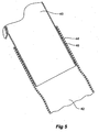
- the stent graft 10 comprises a tubular body 12 of a biocompatible graft material such as Dacron supported by a plurality of self expanding zigzag Gianturco stents 14. At least the self expanding stent 16 at the distal end 18 of the stent graft 10 is internal and the other stents are preferably external.
- a side arm 20 is stitched into the main body by stitching 22 and extends away from the body at an angle towards the distal end of the stent graft.
- the side arm is formed from a biocompatible graft material such as Dacron.
- An extension piece 24 extends from the side arm 20 with an overlapped portion 26.
- the extension piece 24 is formed from ThoralonTM which is a polyurethane multi-polymer comprising a high flex life elastomer base with a surface modifying agent comprising siloxane which is manufactured by Thorotec Corporation (Pleasanton, CA USA). This material is substantially transparent and hence the distal end 27 of the side arm 20 can be seen through it.
- the extension piece 24 can be adhered to the side arm 20 in the overlap region by use of a ThoralonTM solution.
- a ThoralonTM solution One method by which a Thoralon tube may be adhered to the biocompatible graft material side arm 20 is as follows. The overlapping portion 26 of the side arm is first soaked with low concentration Thoralon solution and then it is dried. The tubular Thoralon graft is then adhered onto the overlapping portion 26 by using a Thoralon solution and the solution is cured.
- a first advantage of using ThoralonTM is that even after it is compressed into a small size for deployment it is resilient and can return to its original shape after deployment. This makes it possible to deploy the extension piece into a vessel.
- ThoralonTM polymer is particularly hemocompatible because of the siloxane continually migrates to the blood-contacting surfaces to inhibit the attachment of proteins such as fibrin thereto.
- Figure 2 and Figure 4 show the arrangement of the extension piece during deployment. It will be seen that the extension piece 24 is folded back inside itself and inside the side arm 20 but with its distal end 30 adjacent the distal end 27 of the side arm 20. In Figure 4 in particular it can be seen also that there is a radiopaque marker 28 embedded into the ThoralonTM extension piece 24 to assist with visualisation during deployment.
- Figure 3 shows the side arm stent graft and extension piece of Figure 1 after deployment and placement of a bare self expanding stent deployed through the extension piece.
- a bare stent 32 has been deployed partly within the side arm 20 and partly within the extension piece 24 and just extending out of the distal end 30 of the extension piece 24.
- the bare stent 32 has a radiopaque marker 34 mounted into its distal end 35 to assist with visualisation and accurate placement during deployment.
- the bare stent 32 can be a self expanding stent such as a ZilverTM stent (Cook, Bloomington, IN USA) or a balloon expandable stent carried in and deployed on a balloon catheter.
- a deployment device or introducer for such a bare stent may have a diameter of 7 French which is compatible with existing delivery systems for stent grafts. It will be noted from Figure 3 that the radiopaque marker 28 embedded into the ThoralonTM extension piece 24 is now some distance from the side arm 20 so that the physician is able to determine by radiography whether successful extension of the extension piece has occurred.
- FIG 5 shows detail of an alternative embodiment of side arm stent graft with extension piece.
- the side arm 40 of a stent graft has an extension piece 42 fastened to it on the outside of the side arm 40 by the use of a ThoralonTM adhesive 46.
- One method of fastening is by adhering as discussed above.
- the extension piece 42 has a ribbon 44 of nitinol embedded into it and extending longitudinally along the extension piece.
- the nitinol ribbon 44 provides a resilient reinforcement for the extension piece 42.
- the reinforcement may be a resilient wire.
- the wire or ribbon may alternatively be formed from resilient stainless steel.
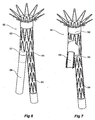
- Figure 6 shows an alternative embodiment of stent graft according to the invention including an extension piece according to the present invention
- Figure 7 shows the embodiment of Figure 6 with the stent graft part cutaway to show the extension piece retracted into the stent graft for deployment.
- FIG. 6 there is illustrated a bifurcated stent graft suitable for deployment into an aorta to span an aneurysm which incorporates the aortic bifurcation.
- the stent graft 50 has a tubular body 52 and a first leg 54 extending from a bifurcation 55.
- a second leg extending from the bifurcation 55 is comprised partly as a leg 57 being a continuation of the tubular body 52 and then an extension piece 59 comprised from a elastomeric material such as expanded PTFE or Thoralon.
- the extension piece 59 is fastened to the leg 57 by adhering as discussed above or any other fastening technique such as stitching.
- Figure 7 shows the embodiment of Figure 6 but part of the tubular body 52 is cutaway to show the extension piece 59 folded back into the main tubular body for deployment.
- the stent graft Upon deployment of the stent graft according to this embodiment the stent graft is deployed so that the tubular body 52 is in the aorta and the leg 54 extends down one of the iliac arteries and then the extension piece 59 can then be pushed outto extend down the contra-lateral iliac artery and then a bare stent such as a self expanding or balloon expandable stent can be deployed into the contra-lateral iliac artery to seal the extension piece against the wall of the contra-lateral iliac artery.
- the extension piece may include a reinforcing ribbon or wire of nitinol or stainless steel and may include one or more radiopaque markers.
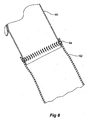
- Figure 8 shows an alternative method of joining the extension piece to the side arm according to the present invention.
- the side arm 60 of a stent graft has an extension piece 62 of a biocompatible elastomeric material stitched to it by stitching 64.
- the stitching provides a fluid type seal between the extension piece and the side arm which reduce the chance of endoleaks after deployment of the stent graft into the vasculature of a patient.
Description
- This invention relates to a medical device and more particularly to a medical device for endovascular deployment into a body lumen such as the vasculature of an animal or human.
- It is known to use branch vessel stent grafts deployed into vasculature of a human or animal to provide an alternate flow path where the vasculature has been damaged by accident or disease. The branch vessel stent graft allows an extension piece to be deployed from a main graft into a side vessel of the vasculature so that blood flow can enter the side vessel.
- The conventional procedure to treat branch vessels utilizes a balloon expandable covered stentwhich is deployed through the side arm ofthe stent graft to connect the side vessels to a bifurcated stent graft. The limitation of a delivery system for such balloon expandable covered stents is normally 7 to 8 French which makes the design of the stent graft deployment system challenging. A further challenge is then providing a sufficient attachment between the branch vessel stent graft and the side arm ofthe main graft since endoleaks can occur and these are of significant concern. A stent graft according to the preamble of claim 1 is known from the document
US-A-2004/0082990 . - It is the object of this invention to provide an alternative branch vessel stent graft which will make the process of deployment of a graft into a branch vessel more straightforward or at least to provide the physician with a useful alternative.
- Throughout this specification the term distal with respect to a portion of the aorta, a deployment device or a prosthesis is the end of the aorta, deployment device or prosthesis further away in the direction of blood flow away from the heart and the term proximal means the portion of the aorta, deployment device or end of the prosthesis nearer to the heart. When applied to other vessels similar terms such as caudal and cranial should be understood.
- According to an aspect of the present invention, there is provided a stent graft as specified in claim 1.
- Preferably the tubular body and the side arm comprise a biocompatible woven or non-woven material selected from the group comprising Dacron and expanded PTFE and the extension piece comprises an elastomeric biocompatible material such as Thoralon™.
- Preferably the extension piece is unstented. The extension piece may comprise, however, a longitudinally extending resilient reinforcement. The longitudinally extending resilient reinforcement may be a ribbon or wire formed from nitinol. The longitudinally extending resilient reinforcement is preferably embedded in the extension piece.
- There can also be placed gold markers embedded in the extension piece to assist with visualisation using radiographic techniques during deployment.
- The unstented extension piece is supported after deployment by a separately deployed self expanding stent assembly or by a separately deployed balloon expandable stent assembly. The separately deployed self expanding stent assembly or a separately deployed balloon expandable stent assembly may have at least one radiopaque marker to assist with visualisation using radiographic techniques during deployment.
- Preferably the tubular body comprises a plurality of self expanding stents and the side arm is stitched to the tubular body. The extension piece is preferably sealingly joined to the side arm by being adhered thereto.
- Alternatively the extension piece is stitched to the side arm using a biocompatible suture material.
- Where the extension piece comprises Thoralon™ it may be sealingly fastened to the side arm by being adhered thereto by the use of a Thoralon™ solution as an adhesive.
- The tubular body is bifurcated and the extension piece comprises a leg extending from a bifurcation in the tubular body.
- According to a second aspect of the present invention, there is provided a kit as specified in
claim 14. - It will be seen that by this invention the stent for the extension piece is deployed in a separate stage than the deployment of the actual graft for the side arm and therefore makes it easier to use any bare stent such as a self expanding or balloon expandable stent for the stent stage. Such a separately deployed bare stent is considerably smaller in diameterthan a covered balloon expandable stent for instance and therefore can be more easily deployed using existing technologies. The graft portion of the side branch is attached securely to the main side arm stent graft and loaded as an integral part. After the stent graft is implanted a bare stent can then subsequently be deployed to keep the branch vessel graft open and attached to the vasculature.
- This arrangement has two significant advantages. First of all there can be a lower system delivery profile for the stent for the side arm.
- A second advantage is that effective sealing can be obtained because the extension piece for the side arm is effectively sealed to the extension piece during manufacture of the stent graft.
- This then generally describes the invention but to assist with understanding reference will now be made to the accompanying drawings which show preferred embodiments of the invention.
In the drawings: -
Figure 1 shows a first view of a side branch stent graft with an extension piece according to one embodiment of the present invention; -
Figure 2 shows the embodiment shown inFigure 1 with the extension piece folded back into the side arm for initial deployment; -
Figure 3 shows the side arm stent graft and extension piece ofFigure 1 after deployment and placement of a bare self expanding stent deployed through the extension piece; -
Figure 4 shows a detail of the side arm ofFigure 2 particularly showing the folded back nature of the extension piece and the radio opaque marker; -
Figure 5 shows detail of an alternative embodiment of stent graft according to the invention in which the extension piece includes a reinforcing ribbon; -
Figure 6 shows an alternative embodiment ofstent graft according to the invention including an extension piece according to the present invention; -
Figure 7 shows the embodiment ofFigure 6 with the extension piece retracted for deployment; and -
Figure 8 shows an alternative method of joining the extension piece to the side arm according to the present invention. - Now looking more closely at the first embodiment of the invention shown in
Figures 1, 2, and 4 it will be seen that thestent graft 10 according to the present invention comprises atubular body 12 of a biocompatible graft material such as Dacron supported by a plurality of self expanding zigzag Gianturcostents 14. At least theself expanding stent 16 at thedistal end 18 of thestent graft 10 is internal and the other stents are preferably external. Aside arm 20 is stitched into the main body by stitching 22 and extends away from the body at an angle towards the distal end of the stent graft. The side arm is formed from a biocompatible graft material such as Dacron.U.S. Provisional Patent Application Serial No. 60/611,744, filed September 21,2004 U.S. Patent Application Serial No. 11/231,621, filed September 21,2005 US-2006/0095118-A1 , andPCT Patent Publication No. WO 06/034276 U.S. Provisional Patent Application Serial No. 60/611,744, filed September 21, 2004 U.S. Patent Application Serial No. 11/231,621, filed September 21,2005 US-2006/0095118-A1 , andPCT Patent Publication No. WO 06/034276 U.S. Provisional Patent Application Serial No. 60/611,744, filed September 21,2004 U.S. Patent Application Serial No. 11/231,621, filed September 21,2005 US-2006/0095118-A1 , andPCT Patent Publication No. WO 06/034276 - An
extension piece 24 extends from theside arm 20 with an overlappedportion 26. Theextension piece 24 is formed from Thoralon™ which is a polyurethane multi-polymer comprising a high flex life elastomer base with a surface modifying agent comprising siloxane which is manufactured by Thorotec Corporation (Pleasanton, CA USA). This material is substantially transparent and hence thedistal end 27 of theside arm 20 can be seen through it. - The
extension piece 24 can be adhered to theside arm 20 in the overlap region by use of a Thoralon™ solution. One method by which a Thoralon tube may be adhered to the biocompatible graftmaterial side arm 20 is as follows. The overlappingportion 26 of the side arm is first soaked with low concentration Thoralon solution and then it is dried. The tubular Thoralon graft is then adhered onto the overlappingportion 26 by using a Thoralon solution and the solution is cured. - A first advantage of using Thoralon™ is that even after it is compressed into a small size for deployment it is resilient and can return to its original shape after deployment. This makes it possible to deploy the extension piece into a vessel.
- A further advantage is that the Thoralon™ polymer is particularly hemocompatible because of the siloxane continually migrates to the blood-contacting surfaces to inhibit the attachment of proteins such as fibrin thereto.
-
Figure 2 and Figure 4 show the arrangement of the extension piece during deployment. It will be seen that theextension piece 24 is folded back inside itself and inside theside arm 20 but with itsdistal end 30 adjacent thedistal end 27 of theside arm 20. InFigure 4 in particular it can be seen also that there is aradiopaque marker 28 embedded into the Thoralon™ extension piece 24 to assist with visualisation during deployment. -
Figure 3 shows the side arm stent graft and extension piece ofFigure 1 after deployment and placement of a bare self expanding stent deployed through the extension piece. Abare stent 32 has been deployed partly within theside arm 20 and partly within theextension piece 24 and just extending out of thedistal end 30 of theextension piece 24. Thebare stent 32 has aradiopaque marker 34 mounted into its distal end 35 to assist with visualisation and accurate placement during deployment. Thebare stent 32 can be a self expanding stent such as a Zilver™ stent (Cook, Bloomington, IN USA) or a balloon expandable stent carried in and deployed on a balloon catheter. A deployment device or introducer for such a bare stent may have a diameter of 7 French which is compatible with existing delivery systems for stent grafts. It will be noted fromFigure 3 that theradiopaque marker 28 embedded into the Thoralon™ extension piece 24 is now some distance from theside arm 20 so that the physician is able to determine by radiography whether successful extension of the extension piece has occurred. -
Figure 5 shows detail of an alternative embodiment of side arm stent graft with extension piece. In this embodiment theside arm 40 of a stent graft has anextension piece 42 fastened to it on the outside of theside arm 40 by the use of aThoralon™ adhesive 46. One method of fastening is by adhering as discussed above. Theextension piece 42 has aribbon 44 of nitinol embedded into it and extending longitudinally along the extension piece. By this arrangement when the extension piece is extended from the position where it is retracted within the side arm as shown inFigure 4 for instance to the extended configuration as shown inFigure 1 for instance the nitinol ribbon assists with straightening and reinforcing the extension piece. Hence thenitinol ribbon 44 provides a resilient reinforcement for theextension piece 42. Alternatively the reinforcement may be a resilient wire. The wire or ribbon may alternatively be formed from resilient stainless steel. -
Figure 6 shows an alternative embodiment of stent graft according to the invention including an extension piece according to the present invention, andFigure 7 shows the embodiment ofFigure 6 with the stent graft part cutaway to show the extension piece retracted into the stent graft for deployment. - In
Figure 6 there is illustrated a bifurcated stent graft suitable for deployment into an aorta to span an aneurysm which incorporates the aortic bifurcation. Thestent graft 50 has atubular body 52 and afirst leg 54 extending from abifurcation 55. A second leg extending from thebifurcation 55 is comprised partly as aleg 57 being a continuation of thetubular body 52 and then anextension piece 59 comprised from a elastomeric material such as expanded PTFE or Thoralon. Theextension piece 59 is fastened to theleg 57 by adhering as discussed above or any other fastening technique such as stitching. -
Figure 7 shows the embodiment ofFigure 6 but part of thetubular body 52 is cutaway to show theextension piece 59 folded back into the main tubular body for deployment. - Upon deployment of the stent graft according to this embodiment the stent graft is deployed so that the
tubular body 52 is in the aorta and theleg 54 extends down one of the iliac arteries and then theextension piece 59 can then be pushed outto extend down the contra-lateral iliac artery and then a bare stent such as a self expanding or balloon expandable stent can be deployed into the contra-lateral iliac artery to seal the extension piece against the wall of the contra-lateral iliac artery.
The extension piece may include a reinforcing ribbon or wire of nitinol or stainless steel and may include one or more radiopaque markers. -
Figure 8 shows an alternative method of joining the extension piece to the side arm according to the present invention. In this embodiment theside arm 60 of a stent graft has anextension piece 62 of a biocompatible elastomeric material stitched to it by stitching 64. The stitching provides a fluid type seal between the extension piece and the side arm which reduce the chance of endoleaks after deployment of the stent graft into the vasculature of a patient.
Claims (14)
- A stent graft (10; 50) comprising a tubular body (12; 52) of a biocompatible material with a main lumen therethrough, a side arm (20; 40; 57; 60) extending from the tubular body with a side arm lumen therethrough and being fastened to the tubular body, the side arm having a distal end (27) remote from its connection to the tubular body, the main lumen being in fluid communication with the side arm lumen characterised by an unstented tubular extension piece (24; 42; 59; 62) sealingly fastened to the distal end of the side arm and extending therefrom, wherein the tubular extension piece is tucked back into the side arm for deployment of the stent graft into a body lumen and is extendable from the side arm during deployment of the stent graft.
- A stent graft (10; 50) as claimed in claim 1, wherein the tubular extension piece (24; 42; 59; 62) is tucked back inside the side arm (20; 40; 57; 60) such that its distal end (30) is adjacent the distal end (27) of the side arm.
- A stent graft (50) as claimed in claim 1 or 2, wherein the tubular body is a bifurcated tubular body (52) and wherein the side arm is a leg (57) of the bifurcated tubular body.
- A stent graft (10; 50) as claimed in claim 1, 2 or 3, wherein the tubular body (12; 52) and the side arm (20; 40; 57; 60) comprise a biocompatible woven or non-woven material of Dacron or expanded PTFE.
- A stent graft (10; 50) as claimed in any preceding claim, wherein the extension piece (24; 42; 59; 62) comprises an elastomeric biocompatible material of Thoralon™ polymer or expanded PTFE.
- A stent graft (10; 50) as claimed in any preceding claim, wherein the extension piece (42) includes a longitudinally extending resilient reinforcement (44).
- A stent graft (10; 50) as claimed in claim 6, wherein the longitudinally extending resilient reinforcement comprises a ribbon (44) or wire formed from nitinol.
- A stent graft (10; 50) as claimed in claim 6 or 7, wherein the longitudinally extending resilient reinforcement (44) is embedded in the extension piece (42).
- A stent graft (10; 50) as claimed in any preceding claim, wherein the extension piece (24; 42; 59) is sealingly fastened to the side arm (20; 40; 57) by being adhered thereto.
- A stent graft (10; 50) as claimed in any preceding claim, wherein the extension piece (24; 42; 59) comprises Thoralon™ polymer and the extension piece is fastened to the side arm (20; 40; 57) by being adhered thereto by the use of a Thoralon™ solution.
- A stent graft (10; 50) as claimed in any of claims 1 to 8, wherein the extension piece (62) is fastened to the side arm (60) by being stitched thereto.
- A stent graft (10; 50) as claimed in any preceding claim, comprising a radiopaque marker (28) embedded into the extension piece (24; 42; 59; 62).
- A stent graft (10; 50) as claimed in any preceding claim, wherein the extension piece (42) includes a longitudinally extending resilient reinforcement (44) embedded therein, the extension piece comprises Thoralon™ polymer or expanded PTFE, and wherein at least one radiopaque marker (28) is embedded into the extension piece.
- A kit including a stent graft (10; 50) as claimed in any preceding claim, and a separately deployable self-expanding stent assembly or a separately deployable balloon expandable stent assembly.
Applications Claiming Priority (2)
| Application Number | Priority Date | Filing Date | Title |
|---|---|---|---|
| US69717405P | 2005-07-07 | 2005-07-07 | |
| PCT/US2006/026226 WO2007008533A1 (en) | 2005-07-07 | 2006-07-06 | Branch vessel stent graft |
Publications (2)
| Publication Number | Publication Date |
|---|---|
| EP1906878A1 EP1906878A1 (en) | 2008-04-09 |
| EP1906878B1 true EP1906878B1 (en) | 2015-08-19 |
Family
ID=36974699
Family Applications (1)
| Application Number | Title | Priority Date | Filing Date |
|---|---|---|---|
| EP06774523.2A Active EP1906878B1 (en) | 2005-07-07 | 2006-07-06 | Branch vessel stent graft |
Country Status (6)
| Country | Link |
|---|---|
| US (1) | US9155611B2 (en) |
| EP (1) | EP1906878B1 (en) |
| JP (1) | JP4887361B2 (en) |
| AU (1) | AU2006269444B2 (en) |
| CA (1) | CA2613330C (en) |
| WO (1) | WO2007008533A1 (en) |
Families Citing this family (37)
| Publication number | Priority date | Publication date | Assignee | Title |
|---|---|---|---|---|
| US7147661B2 (en) | 2001-12-20 | 2006-12-12 | Boston Scientific Santa Rosa Corp. | Radially expandable stent |
| US20070198078A1 (en) | 2003-09-03 | 2007-08-23 | Bolton Medical, Inc. | Delivery system and method for self-centering a Proximal end of a stent graft |
| US7763063B2 (en) | 2003-09-03 | 2010-07-27 | Bolton Medical, Inc. | Self-aligning stent graft delivery system, kit, and method |
| US11259945B2 (en) | 2003-09-03 | 2022-03-01 | Bolton Medical, Inc. | Dual capture device for stent graft delivery system and method for capturing a stent graft |
| US11596537B2 (en) | 2003-09-03 | 2023-03-07 | Bolton Medical, Inc. | Delivery system and method for self-centering a proximal end of a stent graft |
| US20080264102A1 (en) | 2004-02-23 | 2008-10-30 | Bolton Medical, Inc. | Sheath Capture Device for Stent Graft Delivery System and Method for Operating Same |
| US8292943B2 (en) | 2003-09-03 | 2012-10-23 | Bolton Medical, Inc. | Stent graft with longitudinal support member |
| US8500792B2 (en) | 2003-09-03 | 2013-08-06 | Bolton Medical, Inc. | Dual capture device for stent graft delivery system and method for capturing a stent graft |
| US9198786B2 (en) | 2003-09-03 | 2015-12-01 | Bolton Medical, Inc. | Lumen repair device with capture structure |
| JP5083766B2 (en) | 2004-09-21 | 2012-11-28 | ウィリアム・エイ・クック・オーストラリア・プロプライエタリー・リミテッド | Side branch stent graft |
| WO2006065644A1 (en) * | 2004-12-17 | 2006-06-22 | William A. Cook Australia Pty. Ltd. | Stented side branch graft |
| US9358097B2 (en) * | 2006-03-29 | 2016-06-07 | The Cleveland Clinic Foundation | Iliac leg extension stent graft |
| US20090030502A1 (en) * | 2007-07-26 | 2009-01-29 | Jichao Sun | Socket For Fenestrated Tubular Prosthesis |
| US20090043376A1 (en) * | 2007-08-08 | 2009-02-12 | Hamer Rochelle M | Endoluminal Prosthetic Conduit Systems and Method of Coupling |
| AU2008323540B2 (en) * | 2007-11-15 | 2015-02-12 | W. L. Gore & Associates, Inc. | Hybrid intraluminal device |
| US20090164001A1 (en) * | 2007-12-21 | 2009-06-25 | Biggs David P | Socket For Fenestrated Tubular Prosthesis |
| AU2009213159B2 (en) | 2008-02-11 | 2013-02-21 | Cook Medical Technologies Llc | Prosthesis coupling device and method |
| US9364314B2 (en) | 2008-06-30 | 2016-06-14 | Bolton Medical, Inc. | Abdominal aortic aneurysms: systems and methods of use |
| US8353943B2 (en) * | 2008-08-29 | 2013-01-15 | Cook Medical Technologies Llc | Variable weave graft with metal strand reinforcement for in situ fenestration |
| BRPI1012599A2 (en) | 2009-03-13 | 2016-03-22 | Bolton Medical Inc | system and method for placing an endoluminal prosthesis in a surgical site |
| US8052741B2 (en) * | 2009-03-23 | 2011-11-08 | Medtronic Vascular, Inc. | Branch vessel prosthesis with a roll-up sealing assembly |
| WO2011056638A1 (en) * | 2009-10-27 | 2011-05-12 | Bolton Medical, Inc. | Endovascular grafts and methods of use |
| EP3053545B1 (en) | 2011-04-28 | 2019-09-18 | Cook Medical Technologies LLC | Apparatus for facilitating deployment of an endoluminal prosthesis |
| US9066824B2 (en) * | 2011-10-21 | 2015-06-30 | The Charlotte-Mecklenburg Hospital Authority | Method and apparatus for endovascular therapy of aortic pathology |
| WO2013154749A1 (en) | 2012-04-12 | 2013-10-17 | Bolton Medical, Inc. | Vascular prosthetic delivery device and method of use |
| EP2961358B1 (en) * | 2013-02-28 | 2019-06-26 | Boston Scientific Scimed, Inc. | Implantable medical devices for reduced tissue inflammation |
| US9439751B2 (en) | 2013-03-15 | 2016-09-13 | Bolton Medical, Inc. | Hemostasis valve and delivery systems |
| CN107625562B (en) * | 2016-07-13 | 2020-02-04 | 先健科技(深圳)有限公司 | Branch type covered stent |
| AU2016210717B1 (en) | 2016-08-04 | 2017-05-18 | Cook Medical Technologies Llc | An endograft for treating branched vessels |
| US10548710B2 (en) | 2017-02-24 | 2020-02-04 | The Cleveland Clinic Foundation | Method and apparatus for time-differential deployment of an endovascular device within a body lumen |
| US11446168B2 (en) | 2017-04-25 | 2022-09-20 | Cook Medical Technologies Llc | Prosthesis with side branch and method of making the same |
| CN110314014A (en) * | 2018-03-30 | 2019-10-11 | 上海微创心脉医疗科技股份有限公司 | Intravascular stent and its traction device |
| DE102018108584A1 (en) * | 2018-04-11 | 2019-10-31 | Freistaat Bayern vertreten durch Hochschule Hof, Institut für Materialwissenschaften | Branched stent and stent system |
| CN109276346B (en) * | 2018-11-01 | 2020-08-25 | 浙江大学 | Split type blood vessel covered stent |
| WO2020134920A1 (en) * | 2018-12-28 | 2020-07-02 | 深圳市先健畅通医疗有限公司 | Covered stent and preparation method therefor |
| US11219518B2 (en) * | 2019-11-15 | 2022-01-11 | Medtronic Vascular, Inc. | Oblique seam for reduced stent graft packing density in delivery system |
| US20210267748A1 (en) * | 2020-03-02 | 2021-09-02 | Medtronic Vascular, Inc. | Trifurcated stent graft |
Family Cites Families (19)
| Publication number | Priority date | Publication date | Assignee | Title |
|---|---|---|---|---|
| CA2065634C (en) | 1991-04-11 | 1997-06-03 | Alec A. Piplani | Endovascular graft having bifurcation and apparatus and method for deploying the same |
| US5755770A (en) * | 1995-01-31 | 1998-05-26 | Boston Scientific Corporatiion | Endovascular aortic graft |
| GB9518400D0 (en) | 1995-09-08 | 1995-11-08 | Anson Medical Ltd | A surgical graft/stent system |
| US6045557A (en) | 1995-11-10 | 2000-04-04 | Baxter International Inc. | Delivery catheter and method for positioning an intraluminal graft |
| US6306164B1 (en) * | 1997-09-05 | 2001-10-23 | C. R. Bard, Inc. | Short body endoprosthesis |
| US6287335B1 (en) * | 1999-04-26 | 2001-09-11 | William J. Drasler | Intravascular folded tubular endoprosthesis |
| US6383171B1 (en) * | 1999-10-12 | 2002-05-07 | Allan Will | Methods and devices for protecting a passageway in a body when advancing devices through the passageway |
| US6663667B2 (en) | 1999-12-29 | 2003-12-16 | Edwards Lifesciences Corporation | Towel graft means for enhancing tissue ingrowth in vascular grafts |
| US6569191B1 (en) * | 2000-07-27 | 2003-05-27 | Bionx Implants, Inc. | Self-expanding stent with enhanced radial expansion and shape memory |
| WO2002015951A2 (en) * | 2000-08-23 | 2002-02-28 | Thoratec Corporation | Coated vascular grafts and methods of use |
| AUPR847301A0 (en) * | 2001-10-26 | 2001-11-15 | Cook Incorporated | Endoluminal prostheses for curved lumens |
| WO2003082153A2 (en) * | 2002-03-25 | 2003-10-09 | Cook Incorporated | Branched vessel prothesis |
| US7655036B2 (en) * | 2002-04-24 | 2010-02-02 | Medtronic Vascular, Inc. | Bifurcated endoluminal prosthetic assembly and method |
| ATE417570T1 (en) | 2002-08-23 | 2009-01-15 | Cook William A Australia | COMPOSITE PROSTHESIS |
| EP2065015B1 (en) * | 2003-04-03 | 2015-06-24 | Cook Medical Technologies LLC | Stent-graft |
| US8734501B2 (en) | 2003-10-10 | 2014-05-27 | Cook Medical Technologies Llc | Composite stent graft |
| US20050080482A1 (en) * | 2003-10-14 | 2005-04-14 | Craig Bonsignore | Graft coupling apparatus and methods of using same |
| DE602004028863D1 (en) * | 2003-12-17 | 2010-10-07 | Cook Inc | ASSOCIATED LEG EXTENSIONS FOR AN ENDOLUMINAL PROSTHESIS |
| JP5083766B2 (en) | 2004-09-21 | 2012-11-28 | ウィリアム・エイ・クック・オーストラリア・プロプライエタリー・リミテッド | Side branch stent graft |
-
2006
- 2006-07-06 JP JP2008520366A patent/JP4887361B2/en active Active
- 2006-07-06 WO PCT/US2006/026226 patent/WO2007008533A1/en active Application Filing
- 2006-07-06 AU AU2006269444A patent/AU2006269444B2/en not_active Ceased
- 2006-07-06 EP EP06774523.2A patent/EP1906878B1/en active Active
- 2006-07-06 CA CA2613330A patent/CA2613330C/en active Active
- 2006-07-06 US US11/481,763 patent/US9155611B2/en not_active Expired - Fee Related
Also Published As
| Publication number | Publication date |
|---|---|
| US9155611B2 (en) | 2015-10-13 |
| US20070010874A1 (en) | 2007-01-11 |
| CA2613330C (en) | 2014-08-26 |
| CA2613330A1 (en) | 2007-01-18 |
| EP1906878A1 (en) | 2008-04-09 |
| WO2007008533A1 (en) | 2007-01-18 |
| AU2006269444A1 (en) | 2007-01-18 |
| JP4887361B2 (en) | 2012-02-29 |
| JP2009500117A (en) | 2009-01-08 |
| AU2006269444B2 (en) | 2011-07-21 |
Similar Documents
| Publication | Publication Date | Title |
|---|---|---|
| EP1906878B1 (en) | Branch vessel stent graft | |
| AU2003258976B2 (en) | Thoracic aortic aneurysm stent graft. | |
| EP3034036B1 (en) | Paraplegia prevention stent graft | |
| EP1356786B1 (en) | Endoluminal prosthetic assembly | |
| US6361557B1 (en) | Staplebutton radiopaque marker | |
| JP4284366B2 (en) | Prosthesis system and method sized and configured for receiving and holding fasteners | |
| EP1765222B1 (en) | Stent graft with internal tube | |
| EP1791498B1 (en) | Stent graft with integral side arm | |
| JP5531016B2 (en) | Stent graft fixation coupling | |
| EP3424463A1 (en) | Aorta and branch vessel stent grafts and system | |
| EP1998715B1 (en) | Iliac leg extension stent graft | |
| AU2004287354A1 (en) | Catheter-based fastener implantation apparatus and methods | |
| WO2005058202A1 (en) | Interconnected leg extensions for an endoluminal prostehsis | |
| EP1025811A2 (en) | Endoluminal prosthesis having radiopaque marker | |
| EP2702960B1 (en) | Endoluminal prosthesis and delivery device |
Legal Events
| Date | Code | Title | Description |
|---|---|---|---|
| PUAI | Public reference made under article 153(3) epc to a published international application that has entered the european phase |
Free format text: ORIGINAL CODE: 0009012 |
|
| 17P | Request for examination filed |
Effective date: 20080107 |
|
| AK | Designated contracting states |
Kind code of ref document: A1 Designated state(s): AT BE BG CH CY CZ DE DK EE ES FI FR GB GR HU IE IS IT LI LT LU LV MC NL PL PT RO SE SI SK TR |
|
| RAP1 | Party data changed (applicant data changed or rights of an application transferred) |
Owner name: MED INSTITUTE, INC. |
|
| 17Q | First examination report despatched |
Effective date: 20110518 |
|
| RAP1 | Party data changed (applicant data changed or rights of an application transferred) |
Owner name: COOK MEDICAL TECHNOLOGIES LLC |
|
| RAP1 | Party data changed (applicant data changed or rights of an application transferred) |
Owner name: COOK MEDICAL TECHNOLOGIES LLC |
|
| DAX | Request for extension of the european patent (deleted) | ||
| GRAP | Despatch of communication of intention to grant a patent |
Free format text: ORIGINAL CODE: EPIDOSNIGR1 |
|
| INTG | Intention to grant announced |
Effective date: 20150212 |
|
| GRAP | Despatch of communication of intention to grant a patent |
Free format text: ORIGINAL CODE: EPIDOSNIGR1 |
|
| INTG | Intention to grant announced |
Effective date: 20150410 |
|
| GRAS | Grant fee paid |
Free format text: ORIGINAL CODE: EPIDOSNIGR3 |
|
| GRAA | (expected) grant |
Free format text: ORIGINAL CODE: 0009210 |
|
| AK | Designated contracting states |
Kind code of ref document: B1 Designated state(s): AT BE BG CH CY CZ DE DK EE ES FI FR GB GR HU IE IS IT LI LT LU LV MC NL PL PT RO SE SI SK TR |
|
| REG | Reference to a national code |
Ref country code: GB Ref legal event code: FG4D |
|
| REG | Reference to a national code |
Ref country code: CH Ref legal event code: EP |
|
| REG | Reference to a national code |
Ref country code: IE Ref legal event code: FG4D |
|
| REG | Reference to a national code |
Ref country code: AT Ref legal event code: REF Ref document number: 743236 Country of ref document: AT Kind code of ref document: T Effective date: 20150915 |
|
| REG | Reference to a national code |
Ref country code: DE Ref legal event code: R096 Ref document number: 602006046347 Country of ref document: DE |
|
| REG | Reference to a national code |
Ref country code: AT Ref legal event code: MK05 Ref document number: 743236 Country of ref document: AT Kind code of ref document: T Effective date: 20150819 |
|
| REG | Reference to a national code |
Ref country code: LT Ref legal event code: MG4D |
|
| REG | Reference to a national code |
Ref country code: NL Ref legal event code: MP Effective date: 20150819 |
|
| PG25 | Lapsed in a contracting state [announced via postgrant information from national office to epo] |
Ref country code: LT Free format text: LAPSE BECAUSE OF FAILURE TO SUBMIT A TRANSLATION OF THE DESCRIPTION OR TO PAY THE FEE WITHIN THE PRESCRIBED TIME-LIMIT Effective date: 20150819 Ref country code: FI Free format text: LAPSE BECAUSE OF FAILURE TO SUBMIT A TRANSLATION OF THE DESCRIPTION OR TO PAY THE FEE WITHIN THE PRESCRIBED TIME-LIMIT Effective date: 20150819 Ref country code: LV Free format text: LAPSE BECAUSE OF FAILURE TO SUBMIT A TRANSLATION OF THE DESCRIPTION OR TO PAY THE FEE WITHIN THE PRESCRIBED TIME-LIMIT Effective date: 20150819 Ref country code: GR Free format text: LAPSE BECAUSE OF FAILURE TO SUBMIT A TRANSLATION OF THE DESCRIPTION OR TO PAY THE FEE WITHIN THE PRESCRIBED TIME-LIMIT Effective date: 20151120 |
|
| PG25 | Lapsed in a contracting state [announced via postgrant information from national office to epo] |
Ref country code: PT Free format text: LAPSE BECAUSE OF FAILURE TO SUBMIT A TRANSLATION OF THE DESCRIPTION OR TO PAY THE FEE WITHIN THE PRESCRIBED TIME-LIMIT Effective date: 20151221 Ref country code: SE Free format text: LAPSE BECAUSE OF FAILURE TO SUBMIT A TRANSLATION OF THE DESCRIPTION OR TO PAY THE FEE WITHIN THE PRESCRIBED TIME-LIMIT Effective date: 20150819 Ref country code: ES Free format text: LAPSE BECAUSE OF FAILURE TO SUBMIT A TRANSLATION OF THE DESCRIPTION OR TO PAY THE FEE WITHIN THE PRESCRIBED TIME-LIMIT Effective date: 20150819 Ref country code: PL Free format text: LAPSE BECAUSE OF FAILURE TO SUBMIT A TRANSLATION OF THE DESCRIPTION OR TO PAY THE FEE WITHIN THE PRESCRIBED TIME-LIMIT Effective date: 20150819 Ref country code: IS Free format text: LAPSE BECAUSE OF FAILURE TO SUBMIT A TRANSLATION OF THE DESCRIPTION OR TO PAY THE FEE WITHIN THE PRESCRIBED TIME-LIMIT Effective date: 20151219 Ref country code: AT Free format text: LAPSE BECAUSE OF FAILURE TO SUBMIT A TRANSLATION OF THE DESCRIPTION OR TO PAY THE FEE WITHIN THE PRESCRIBED TIME-LIMIT Effective date: 20150819 |
|
| PG25 | Lapsed in a contracting state [announced via postgrant information from national office to epo] |
Ref country code: NL Free format text: LAPSE BECAUSE OF FAILURE TO SUBMIT A TRANSLATION OF THE DESCRIPTION OR TO PAY THE FEE WITHIN THE PRESCRIBED TIME-LIMIT Effective date: 20150819 |
|
| PG25 | Lapsed in a contracting state [announced via postgrant information from national office to epo] |
Ref country code: EE Free format text: LAPSE BECAUSE OF FAILURE TO SUBMIT A TRANSLATION OF THE DESCRIPTION OR TO PAY THE FEE WITHIN THE PRESCRIBED TIME-LIMIT Effective date: 20150819 Ref country code: SK Free format text: LAPSE BECAUSE OF FAILURE TO SUBMIT A TRANSLATION OF THE DESCRIPTION OR TO PAY THE FEE WITHIN THE PRESCRIBED TIME-LIMIT Effective date: 20150819 Ref country code: CZ Free format text: LAPSE BECAUSE OF FAILURE TO SUBMIT A TRANSLATION OF THE DESCRIPTION OR TO PAY THE FEE WITHIN THE PRESCRIBED TIME-LIMIT Effective date: 20150819 Ref country code: IT Free format text: LAPSE BECAUSE OF FAILURE TO SUBMIT A TRANSLATION OF THE DESCRIPTION OR TO PAY THE FEE WITHIN THE PRESCRIBED TIME-LIMIT Effective date: 20150819 Ref country code: DK Free format text: LAPSE BECAUSE OF FAILURE TO SUBMIT A TRANSLATION OF THE DESCRIPTION OR TO PAY THE FEE WITHIN THE PRESCRIBED TIME-LIMIT Effective date: 20150819 |
|
| REG | Reference to a national code |
Ref country code: DE Ref legal event code: R097 Ref document number: 602006046347 Country of ref document: DE |
|
| PG25 | Lapsed in a contracting state [announced via postgrant information from national office to epo] |
Ref country code: RO Free format text: LAPSE BECAUSE OF FAILURE TO SUBMIT A TRANSLATION OF THE DESCRIPTION OR TO PAY THE FEE WITHIN THE PRESCRIBED TIME-LIMIT Effective date: 20150819 |
|
| PLBE | No opposition filed within time limit |
Free format text: ORIGINAL CODE: 0009261 |
|
| STAA | Information on the status of an ep patent application or granted ep patent |
Free format text: STATUS: NO OPPOSITION FILED WITHIN TIME LIMIT |
|
| 26N | No opposition filed |
Effective date: 20160520 |
|
| PG25 | Lapsed in a contracting state [announced via postgrant information from national office to epo] |
Ref country code: SI Free format text: LAPSE BECAUSE OF FAILURE TO SUBMIT A TRANSLATION OF THE DESCRIPTION OR TO PAY THE FEE WITHIN THE PRESCRIBED TIME-LIMIT Effective date: 20150819 |
|
| PG25 | Lapsed in a contracting state [announced via postgrant information from national office to epo] |
Ref country code: BE Free format text: LAPSE BECAUSE OF FAILURE TO SUBMIT A TRANSLATION OF THE DESCRIPTION OR TO PAY THE FEE WITHIN THE PRESCRIBED TIME-LIMIT Effective date: 20150819 |
|
| REG | Reference to a national code |
Ref country code: CH Ref legal event code: PL |
|
| PG25 | Lapsed in a contracting state [announced via postgrant information from national office to epo] |
Ref country code: MC Free format text: LAPSE BECAUSE OF FAILURE TO SUBMIT A TRANSLATION OF THE DESCRIPTION OR TO PAY THE FEE WITHIN THE PRESCRIBED TIME-LIMIT Effective date: 20150819 |
|
| PG25 | Lapsed in a contracting state [announced via postgrant information from national office to epo] |
Ref country code: FR Free format text: LAPSE BECAUSE OF NON-PAYMENT OF DUE FEES Effective date: 20160801 Ref country code: CH Free format text: LAPSE BECAUSE OF NON-PAYMENT OF DUE FEES Effective date: 20160731 Ref country code: LI Free format text: LAPSE BECAUSE OF NON-PAYMENT OF DUE FEES Effective date: 20160731 |
|
| REG | Reference to a national code |
Ref country code: FR Ref legal event code: ST Effective date: 20170331 |
|
| PG25 | Lapsed in a contracting state [announced via postgrant information from national office to epo] |
Ref country code: LU Free format text: LAPSE BECAUSE OF NON-PAYMENT OF DUE FEES Effective date: 20160706 |
|
| PG25 | Lapsed in a contracting state [announced via postgrant information from national office to epo] |
Ref country code: HU Free format text: LAPSE BECAUSE OF FAILURE TO SUBMIT A TRANSLATION OF THE DESCRIPTION OR TO PAY THE FEE WITHIN THE PRESCRIBED TIME-LIMIT; INVALID AB INITIO Effective date: 20060706 Ref country code: CY Free format text: LAPSE BECAUSE OF FAILURE TO SUBMIT A TRANSLATION OF THE DESCRIPTION OR TO PAY THE FEE WITHIN THE PRESCRIBED TIME-LIMIT Effective date: 20150819 |
|
| PG25 | Lapsed in a contracting state [announced via postgrant information from national office to epo] |
Ref country code: TR Free format text: LAPSE BECAUSE OF FAILURE TO SUBMIT A TRANSLATION OF THE DESCRIPTION OR TO PAY THE FEE WITHIN THE PRESCRIBED TIME-LIMIT Effective date: 20150819 |
|
| PG25 | Lapsed in a contracting state [announced via postgrant information from national office to epo] |
Ref country code: BG Free format text: LAPSE BECAUSE OF FAILURE TO SUBMIT A TRANSLATION OF THE DESCRIPTION OR TO PAY THE FEE WITHIN THE PRESCRIBED TIME-LIMIT Effective date: 20150819 |
|
| PGFP | Annual fee paid to national office [announced via postgrant information from national office to epo] |
Ref country code: IE Payment date: 20220627 Year of fee payment: 17 Ref country code: GB Payment date: 20220627 Year of fee payment: 17 |
|
| PGFP | Annual fee paid to national office [announced via postgrant information from national office to epo] |
Ref country code: DE Payment date: 20220615 Year of fee payment: 17 |
|
| REG | Reference to a national code |
Ref country code: DE Ref legal event code: R119 Ref document number: 602006046347 Country of ref document: DE |
|
| GBPC | Gb: european patent ceased through non-payment of renewal fee |
Effective date: 20230706 |