EP1906430A1 - Appareil de commutation électrique comprenant un moteur à fente à circuit magnétique ouvrant et procédé d'installation d'une ensemble de moteur à fente dans un interrupteur de circuit - Google Patents
Appareil de commutation électrique comprenant un moteur à fente à circuit magnétique ouvrant et procédé d'installation d'une ensemble de moteur à fente dans un interrupteur de circuit Download PDFInfo
- Publication number
- EP1906430A1 EP1906430A1 EP07019188A EP07019188A EP1906430A1 EP 1906430 A1 EP1906430 A1 EP 1906430A1 EP 07019188 A EP07019188 A EP 07019188A EP 07019188 A EP07019188 A EP 07019188A EP 1906430 A1 EP1906430 A1 EP 1906430A1
- Authority
- EP
- European Patent Office
- Prior art keywords
- slot motor
- conductor
- coupling points
- reverse loop
- split core
- Prior art date
- Legal status (The legal status is an assumption and is not a legal conclusion. Google has not performed a legal analysis and makes no representation as to the accuracy of the status listed.)
- Granted
Links
- 238000000034 method Methods 0.000 title claims description 13
- 239000004020 conductor Substances 0.000 claims abstract description 148
- 230000008878 coupling Effects 0.000 claims abstract description 84
- 238000010168 coupling process Methods 0.000 claims abstract description 84
- 238000005859 coupling reaction Methods 0.000 claims abstract description 84
- 230000007246 mechanism Effects 0.000 claims abstract description 14
- 238000003475 lamination Methods 0.000 claims description 14
- 239000000463 material Substances 0.000 claims description 11
- 229910000831 Steel Inorganic materials 0.000 claims description 10
- 239000010959 steel Substances 0.000 claims description 10
- RYGMFSIKBFXOCR-UHFFFAOYSA-N Copper Chemical compound [Cu] RYGMFSIKBFXOCR-UHFFFAOYSA-N 0.000 claims description 8
- 229910052802 copper Inorganic materials 0.000 claims description 8
- 239000010949 copper Substances 0.000 claims description 8
- 238000010943 off-gassing Methods 0.000 claims description 5
- 238000005452 bending Methods 0.000 claims description 4
- 230000015556 catabolic process Effects 0.000 description 6
- 238000000429 assembly Methods 0.000 description 4
- 230000000712 assembly Effects 0.000 description 4
- 238000009413 insulation Methods 0.000 description 4
- 238000001816 cooling Methods 0.000 description 3
- 235000012489 doughnuts Nutrition 0.000 description 3
- 230000006872 improvement Effects 0.000 description 3
- 239000004593 Epoxy Substances 0.000 description 2
- 239000012212 insulator Substances 0.000 description 2
- 239000000696 magnetic material Substances 0.000 description 2
- 239000003973 paint Substances 0.000 description 2
- 238000000926 separation method Methods 0.000 description 2
- 229920000877 Melamine resin Polymers 0.000 description 1
- 230000008901 benefit Effects 0.000 description 1
- 229920002678 cellulose Polymers 0.000 description 1
- 239000001913 cellulose Substances 0.000 description 1
- 239000003989 dielectric material Substances 0.000 description 1
- 238000009826 distribution Methods 0.000 description 1
- IVJISJACKSSFGE-UHFFFAOYSA-N formaldehyde;1,3,5-triazine-2,4,6-triamine Chemical compound O=C.NC1=NC(N)=NC(N)=N1 IVJISJACKSSFGE-UHFFFAOYSA-N 0.000 description 1
- 239000007789 gas Substances 0.000 description 1
- 239000011521 glass Substances 0.000 description 1
- 238000004519 manufacturing process Methods 0.000 description 1
- 238000001465 metallisation Methods 0.000 description 1
- 230000004048 modification Effects 0.000 description 1
- 238000012986 modification Methods 0.000 description 1
- 229920000728 polyester Polymers 0.000 description 1
- 230000008569 process Effects 0.000 description 1
- 238000010791 quenching Methods 0.000 description 1
- 230000000171 quenching effect Effects 0.000 description 1
- 230000004044 response Effects 0.000 description 1
- 239000007787 solid Substances 0.000 description 1
Images


Classifications
-
- H—ELECTRICITY
- H01—ELECTRIC ELEMENTS
- H01H—ELECTRIC SWITCHES; RELAYS; SELECTORS; EMERGENCY PROTECTIVE DEVICES
- H01H77/00—Protective overload circuit-breaking switches operated by excess current and requiring separate action for resetting
- H01H77/02—Protective overload circuit-breaking switches operated by excess current and requiring separate action for resetting in which the excess current itself provides the energy for opening the contacts, and having a separate reset mechanism
- H01H77/10—Protective overload circuit-breaking switches operated by excess current and requiring separate action for resetting in which the excess current itself provides the energy for opening the contacts, and having a separate reset mechanism with electrodynamic opening
- H01H77/107—Protective overload circuit-breaking switches operated by excess current and requiring separate action for resetting in which the excess current itself provides the energy for opening the contacts, and having a separate reset mechanism with electrodynamic opening characterised by the blow-off force generating means, e.g. current loops
- H01H77/108—Protective overload circuit-breaking switches operated by excess current and requiring separate action for resetting in which the excess current itself provides the energy for opening the contacts, and having a separate reset mechanism with electrodynamic opening characterised by the blow-off force generating means, e.g. current loops comprising magnetisable elements, e.g. flux concentrator, linear slot motor
-
- H—ELECTRICITY
- H01—ELECTRIC ELEMENTS
- H01H—ELECTRIC SWITCHES; RELAYS; SELECTORS; EMERGENCY PROTECTIVE DEVICES
- H01H9/00—Details of switching devices, not covered by groups H01H1/00 - H01H7/00
- H01H9/30—Means for extinguishing or preventing arc between current-carrying parts
- H01H9/34—Stationary parts for restricting or subdividing the arc, e.g. barrier plate
- H01H9/36—Metal parts
- H01H9/362—Mounting of plates in arc chamber
-
- H—ELECTRICITY
- H01—ELECTRIC ELEMENTS
- H01H—ELECTRIC SWITCHES; RELAYS; SELECTORS; EMERGENCY PROTECTIVE DEVICES
- H01H9/00—Details of switching devices, not covered by groups H01H1/00 - H01H7/00
- H01H9/30—Means for extinguishing or preventing arc between current-carrying parts
- H01H9/44—Means for extinguishing or preventing arc between current-carrying parts using blow-out magnet
Definitions
- the invention relates to electrical switching apparatus, such as, for example, circuit breakers and, more particularly, to circuit breakers employing a slot motor.
- the invention also relates to methods of installing slot motor assemblies in circuit interrupters.
- a circuit breaker may include, for example, a line conductor, a load conductor, a fixed contact and a movable contact, with the movable contact being movable into and out of electrically conductive engagement with the fixed contact. This switches the circuit breaker between an on or closed position and an off or open position, or between the on or closed position and a tripped or tripped off position.
- the fixed contact is electrically conductively engaged with one of the line and load conductors
- the movable contact is electrically conductively engaged with the other of the line and load conductors.
- the circuit breaker may also include an operating mechanism having a movable contact arm upon which the movable contact is disposed.
- the contacts may be disposed within a slot motor, which increases interruption performance.
- Ring-shaped or loop-shaped slot motors typically have two assemblies, an upper assembly and a lower assembly. Both of the upper and lower assemblies include a corresponding insulative housing and a plurality of plates composed of magnetically permeable material (e . g ., steel), which surrounds the separable contacts and the movable contact arm of the circuit breaker. The lower assembly is disposed below the fixed contact. When the power circuit is live, an electrical arc may be drawn between the separable contacts during separation.
- the electrical current interacts electromagnetically with the slot motor to induce a magnetic field in the magnetic material of the slot motor, which, in turns, interacts with the separating contacts and the movable contact arm to accelerate the contact opening process.
- slot motors are disclosed in U.S. Patent Nos. 4,375,021 ; 4,546,336 ; 4,546,337 ; 4,549,153 ; 4,970,482 ; 5,694,098 , and 6,281,459 .
- the upper assembly is an inverted U-shaped assembly having a housing assembly 1 and a plurality of plates 2, forming a bight portion 3 and two legs 4,5.
- the upper slot motor assembly is structured to be disposed over the movable contact (not shown) wherein the tips of the upper assembly legs 4,5 contact the lower slot motor assembly (not shown).
- the upper assembly legs 4,5 have an extended length to accommodate the path of travel of the movable contact arm (not shown). That is, the movable contact (not shown) is disposed between the upper assembly legs 4,5 and as the movable contact moves between the first, open position and the second, closed position, the movable contact moves from a position adjacent to the upper assembly bight portion 3 to a position adjacent the tips of the legs 4,5. Accordingly, the legs 4,5 have a sufficient length to accommodate the path of travel of the movable contact arm.
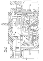
- FIG. 2 shows a circuit breaker 6 including a housing 7, separable contacts 8,9 enclosed by the housing 7, and a spring powered operating mechanism 10 which opens the separable contacts 8,9 to interrupt the current through the conductors of an electrical system (not shown) in response to electrical fault conditions.
- the circuit breaker 6 also includes a loop-shaped slot motor 12 and an arc chute 14.
- the separable contacts 8,9 generally comprise one or more movable contacts 8 and one or more corresponding stationary contacts 9.
- Each movable contact 8 is disposed at or about a first end 16 of a spring-biased movable contact arm 18.
- the spring-biased movable contact arm 18 is pivotably coupled, at or about its second end 20, to a crossbar 22 of the operating mechanism 10.
- the crossbar 22 carries the movable contact arms 18 for all of the poles 24 (only one pole 24 is shown) of the circuit breaker 6, and cooperates with a cradle 26 of the circuit breaker operating mechanism 10 to allow for simultaneous opening and closing of the contacts 8,9 in all of the poles 24.
- the operating mechanism 10 controls the spring-biased movable contact arm 18 to pivot the movable contact 8 into and out of electrical contact with the corresponding stationary contact 9.
- a contact arm spring 28 biases the second end 20 of the movable contact arm 18, proximate the operating mechanism crossbar 22, in order to maintain the closed position (shown in phantom line drawing) of the pair of movable and stationary contacts 8,9.
- a slot motor having a relatively narrow width channel is essential for effective current-limiting and arc quenching.
- assembly of a narrow width channel slot motor becomes a manufacturing challenge since the narrow width channel and the shape of the reverse loop conductor prevent assembly.
- a copper reverse loop conductor 30 is bent upward (not shown) to allow the slot motor 12 to slide around the conductor 30. Then, the copper conductor 30 is re-bent back to its intended position (as shown in Figure 2). The bending stresses the copper conductor 30, which, generally, cannot be reliably re-bent back to the proper position especially with the slot motor 12 in place.
- an electrical switching apparatus comprises: a housing; separable contacts; an operating mechanism structured to open and close the separable contacts; a power conductor comprising a first conductor and a second reverse loop conductor, the second reverse loop conductor carrying one of the separable contacts; and a split core slot motor comprising: a first slot motor portion having a number of coupling points, and a second slot motor portion having a number of corresponding coupling points, wherein the coupling points of the first slot motor portion engage the corresponding coupling points of the second slot motor portion to form the split core slot motor, wherein both of the first and second slot motor portions cooperate to form a base of the split core slot motor, and wherein the base of the split core slot motor is disposed between the first conductor and the second reverse loop conductor.
- the number of coupling points may be one coupling point and the number of corresponding coupling points may be one corresponding coupling point; and the one coupling point and the one corresponding coupling point may be coupled between the first conductor and the second reverse loop conductor.
- the number of coupling points may be two coupling points and the number of corresponding coupling points may be two corresponding coupling points; and the two coupling points and the two corresponding coupling points may be coupled between the first conductor and the second reverse loop conductor.
- the coupling points of the first slot motor portion may engage the corresponding coupling points of the second slot motor portion to form the split core slot motor without deforming the reverse loop conductor.
- Each of the first slot motor portion and the second slot motor portion may comprise an insulative cover made of an out-gassing material.
- the power conductor may further comprise an intermediate conductor having an arcuate profile intermediate the first conductor and the second reverse loop conductor; and the insulative cover may be molded to form fit the arcuate profile of the intermediate conductor.
- an electrical switching apparatus comprises: a housing; separable contacts; an arc chute proximate the separable contacts; an operating mechanism structured to open and close the separable contacts; a power conductor comprising a first conductor and a second reverse loop conductor, the second reverse loop conductor carrying one of the separable contacts; and a split core slot motor comprising: a first slot motor portion having a number of coupling points, and a second slot motor portion having a number of corresponding coupling points, wherein the coupling points of the first slot motor portion engage the corresponding coupling points of the second slot motor portion to form the split core slot motor, wherein both of the first and second slot motor portions cooperate to form a base of the split core slot motor, and wherein the base of the split core slot motor is disposed between the first conductor and the second reverse loop conductor.
- the split core slot motor may have a generally U-shape.
- a method of installing a slot motor assembly in a circuit interrupter comprises: employing a generally U-shaped slot motor assembly having two legs and a base; employing a circuit breaker power conductor including a first conductor and a second reverse loop conductor; passing one of the legs of the generally U-shaped slot motor assembly between the first conductor and the second reverse loop conductor; positioning the base of the generally U-shaped slot motor assembly proximate the second reverse loop conductor; and rotating the generally U-shaped slot motor assembly until the base is between the first conductor and the second reverse loop conductor.
- the method may further comprise disposing the one of the legs of the generally U-shaped slot motor assembly generally planar with respect to the first conductor and the second reverse loop conductor before rotating the generally U-shaped slot motor assembly about 908 until the legs of the generally U-shaped slot motor assembly are generally normal with respect to the first conductor and the second reverse loop conductor.
- number shall mean one or an integer greater than one ( i.e., a plurality).
- the terms "generally U-shaped” or “generally U-shape” shall mean that the shape of a corresponding structure has the general shape of the letter “U,” in which the bottom of such letter or structure is rounded, generally round, square, generally square, or partially round and partially square, or has the general shape of a base member with two leg (or arm) members extending upward from the ends of the base member.
- the invention is described in association with a circuit breaker having a single pole, although the invention is applicable to a wide range of electrical switching apparatus having any suitable number of poles ( e.g ., two; three; or more).
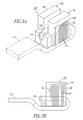
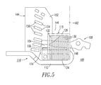
- a circuit breaker 100 ( Figure 5) includes a housing 102 (best shown in phantom line drawing in Figure 3D), separable contacts 104,106, an operating mechanism 108 structured to open and close the separable contacts 104,106, a power conductor 110 (e.g., a "reverse loop'') including a first conductor 112 and a second reverse loop conductor 114, and a split core slot motor 115.
- the second reverse loop conductor 114 carries the stationary contact 106.
- the split core slot motor 115 includes a first slot motor portion 116 ( Figures 3A-3D) having a number of coupling points 118 ( Figures 3A, 3C, 3D), and a second slot motor portion 120 ( Figures 3A, 3C, 3D) having a number of corresponding coupling points 122 (shown in hidden line drawing in Figures 3C and 3D).
- the coupling points 118 of the first slot motor portion 116 engage the corresponding coupling points 122 of the second slot motor portion 120 to form the split core slot motor 115.
- the split core slot motor 115 has a base 124 (e.g., without limitation, bight portion) that is disposed between the first conductor 112 and the second reverse loop conductor 114.
- the base 124 is formed by both of the first and second slot motor portions 116,120.
- the example split core slot motor 115 of Figures 3A-3D has one coupling point that is formed by the engagement of the example single coupling point 118 of the first slot motor portion 116 with the example corresponding single coupling point 122 of the second slot motor portion 120.
- the split core slot motor 115 is formed from two insulative cover portions 126,128 and a plurality of steel laminations 130.
- the external surface of the laminations 130 is covered by a suitable insulative tape 132.
- any suitable insulator e.g ., without limitation, LimitrakTM epoxy paint
- the first and second slot motor portions 116,120 and the insulative cover portions 126,128 hold any suitable slot motor element, which in the example embodiment is the steel laminations 130, although a solid or other suitable slot motor element may be employed.
- the insulative cover portions 126,128 include a surface 133 ( Figure 3D) proximate the stationary contact 106.
- the laminations 130 may be held in place by the internal side walls 134,136 ( Figure 3D) of the circuit breaker 100.
- the first and second slot motor portions 116,120 are coupled together about the power conductor 110, which is then assembled into the circuit breaker 100.
- the side walls 134,136 preferably hold the slot motor 115 together.
- the coupling point 118 is a post and the corresponding coupling point 122 is a recess.
- the coupling point post 118 engages the second slot motor portion 120 at the coupling point recess 122 thereof to form the split core slot motor 115.
- the coupling point 118 of the first slot motor portion 116 engages the corresponding coupling point 122 of the second slot motor portion 120 to form the split core slot motor 115 without deforming the reverse loop conductor 114.
- the first slot motor portion 116 engages the corresponding second slot motor portion 120 without the need to move and, thus, deform ( e.g ., by otherwise bending it away from the first conductor 112) the reverse loop conductor 114.
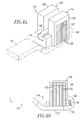
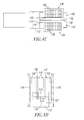
- the example split core slot motor 115' of Figures 4A-4D has two coupling points that are formed by the engagement of the example two coupling points 118' ( e.g ., without limitation, posts) (as best shown in hidden line drawing in Figure 4C) of the first slot motor portion 116' with the example corresponding two coupling points 122' ( e.g ., without limitation, recesses) (as best shown in hidden line drawing in Figure 4C) of the second slot motor portion 120'.
- the coupling points 118',122' are coupled between the first conductor 112' and the second reverse loop conductor 114'.
- the split core slot motor 115' is formed from two insulative cover portions 126',128' and a plurality of steel laminations 130'.
- the external surface of the laminations 130' is covered by a suitable insulative tape 132.
- a suitable insulative tape 132 is shown, any suitable insulator (e.g ., without limitation, LimitrakTM epoxy paint) may be employed.
- the laminations 130' may be held in place by the internal circuit breaker side walls 134',136' ( Figure 4D).
- the side walls 134',136' preferably hold the slot motor 115' together.
- the power conductor 110' includes intermediate conductor 138 having an arcuate profile 140 intermediate the first conductor 112' and the second reverse loop conductor 114'.
- the shapes of the insulative cover portions 126',128' are preferably molded (as best shown in Figure 4B with insulative cover portion 126'), to form fit around the arcuate profile 140 of the intermediate conductor 138.
- the steel volume of the laminations 130' is somewhat less than the steel volume of the laminations 130 of the split core slot motor 115 of Figure 3A due to the laminations 130' being set back away from the bend radius 142 of the intermediate conductor 138 that leads to the second reverse loop conductor 114'. This provides room for the coupling point 118'.
- the coupling points 118' of the first slot motor portion 116' engage the corresponding coupling points 122' of the second slot motor portion 120' to form the split core slot motor 115' without deforming the reverse loop conductor 114'.
- the first slot motor portion 116' engages the corresponding second slot motor portion 120' without the need to move and, thus, deform (e.g., by otherwise bending it away from the first conductor 112') the reverse loop conductor 114'.
- the split core slot motors 115,115' have a generally U-shape.
- the first slot motor portions 116,116' have a generally L-shape.
- the second slot motor portions 120,120' have a corresponding generally L-shape.
- the generally L-shape and the corresponding generally L-shape cooperate to form the generally U-shape of the slot motors 115,115'.
- the slot motor 115 of Figure 3A achieves, for example, 480 V / 200 kA high interruption current (HIC) and 480 V / 10 kA per pole while maintaining the same temperature rise as a standard frame and with a withstand of approximately 13X for a 250 A frame.
- HIC high interruption current
- the slot motor 115' of Figure 4A achieves, for example, 480 V / 150 kA HIC and 480 V / 10 kA single pole while maintaining the same temperature rise as a standard frame and with a withstand of approximately 13X for a 250 A frame.
- the slot motors 115,115' and the respective arc chutes 144,144' of Figures 5 and 6 reduce the let-through energy over known molded case circuit breakers, thereby allowing for increased short circuit interruption ratings.
- the slot motors 115,115' include a generally U-shaped channel that allows the slot motors 115,115' to be installed around the existing reverse loop conductors 114,114', respectively, while, also, remaining relatively closely proximate to the separable contacts 104,106 ( Figure 5). This permits effective arc cooling.
- the open air space 146,146' above the respective generally U-shaped slot motors 115,115' prevents re-striking of the arc between the separable contacts 104,106.
- the much larger air space 146,146' between the movable arm 148 (as best shown with the circuit breaker 100' of Figure 6) and the relatively low profile slot motors 115,115' prevents dielectric breakdown.
- the loss in magnetic field enhancement of the U-shaped, low-profile slot motors 115,115' on movable arm velocity and arc motion, as contrasted with that of conventional loop-shaped slot motors, is minimal compared to the benefit of eliminating breakdown at current-zero.
- the magnetic performance of the generally U-shaped, relatively low-profile slot motors 115,115' is expected to be about equal to that of a conventional slot motor during the most critical initial opening phase of the movable arm 148.
- the insulative cover portions 126,126',128,128' of the slot motors 115,115' of Figures 3A and 4A are preferably made of a suitable out-gassing material. Increased arc cooling is achieved through such insulative covers being made of, for example, cellulose filled melamine formaldehyde (CMF) in close proximity to the separable contacts 104,106 ( Figures 5 and 6).
- CMF cellulose filled melamine formaldehyde
- the relatively low profile, generally U-shaped slot motor configuration and the example CMF insulative cover portions 126,126',128,128' produce desirable gases during interruption in order to attain increased dielectric strength.
- the CMF or other suitable out-gassing material is tightly coupled to, and preferably touches, the side walls 152,152' of the arc chutes 144,144' in order to prevent the circuit breaker base material from interacting with the plasma from the arc and, thus, improve interruption capabilities.
- the disclosed split core slot motors 115,115' have a generally U-shape and snap together around the respective copper reverse loop conductors 114,114'. These arrangements do not require any deformation of such copper conductors 114,114' during assembly.
- This structure provides improvements in the short circuit interruption performance of the circuit breakers 100,100' because of the relatively narrow width channel of the slot motors 115,115' for the movable arm 148, the open ended structure of the generally U-shape, and the gassing material of the insulative cover portions 126,126',128,128'.
- This structure also improves economics by employing a two-piece slot motor that is assembled over the example closed-ended reverse loop conductors 114,114'.
- relatively low profile slot motors 115,115' as contrasted with conventional full-doughnut slot motors, reduce the probability of dielectric breakdown during interruption, especially in relatively "lower" current interruption ( e . g ., about 10 kA).
- insulative cover material is a suitable glass filled polyester.
- a suitable glass filled polyester is marketed by Industrial Dielectrics, Inc. of Noblesville, Indiana. This material preferably provides some suitable out-gassing responsive to an arcing event.
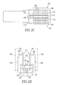
- an arc chute such as 144,144', is proximate the separable contacts 104,106.
- the arc chutes 144,144' include a plurality of spaced apart arc plates 150,150' disposed between insulative side members 152,152', respectively.
- the arc plates 150,150' include edges 154,154' facing the respective split core slot motors 115,115'.
- the end edges 155 of a number of the arc plates 156 are separated from the insulative cover portion 126' (and the other insulative cover portion 128' of Figure 4B) by, preferably, at least about 0.025", and more preferably about 0.1" air space. This enhances the interruption performance.
- Each of the insulative side members 152 and 152' engages a corresponding one of the respective insulative cover portions 126 (and the other insulative cover portion 128 of Figure 3B) and 126' (and the other insulative cover portion 128' of Figure 4B).
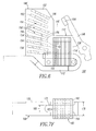
- a generally U-shaped slot motor 160 including two legs 162,164 and a base 166, a circuit breaker power conductor 168 including a first conductor 170 and a second reverse loop conductor 172 are shown in various sequential stages of assembly.
- the cover 174 of the slot motor 160 preferably provides insulation as well as desirable gasses to promote good arc interruption.
- the relatively narrow width channel 176 of the slot motor 160 locates the gassing material in close proximity to the arc and the separable contacts (not shown) to promote efficient cooling of the arc.
- the U-shape or general half doughnut shape of the slot motor 160 prevents arc tracking and subsequent breakdown commonly seen in conventional full doughnut slot motors.
- the slot motor 160 is installed in a circuit interrupter (not shown), such as the circuit breaker 100 of Figure 5, including the power conductor 168 as follows. First, one of the legs, such as 164, of the generally U-shaped slot motor 160 is passed between the first conductor 170 and the second reverse loop conductor 172, as shown in Figure 7A. Then, as also shown in Figure 7A, the base 166 of the generally U-shaped slot motor 160 is positioned proximate the second reverse loop conductor 172. There, the legs 162,164 are generally planar with respect to the first conductor 170 and the second reverse loop conductor 172.
- the generally U-shaped slot motor 160 is rotated, as shown in Figures 7B-7E, until the base 166 is between the first conductor 170 and the second reverse loop conductor 172.
- the generally U-shaped slot motor 160 is fully rotated about 908 (with respect to the initial position of Figure 7A) until the legs 162,164 are generally normal with respect to the first conductor 170 and the second reverse loop conductor 172.
- Figure 7F shows the generally U-shaped slot motor 160 and the circuit breaker power conductor 168 after being assembled.
- the radius outer corners 184,186 ( Figure 7B) on the edges of the slot motor 160 assist in assembly.
- the first conductor 170 has a first width 178
- the second reverse loop conductor 172 has a second smaller width 180.
- the U-shaped slot motor 160 employs a single-piece U-shaped insulative cover 174 holding a number of slot motor elements 182.
- the geometry of the U-shaped slot motor 160 allows it to be slid around the reverse loop conductor 172 rather than having to bend that conductor. This avoids adding stresses that might cause undesired contact height changes.
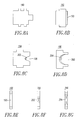
- Figures 8A-8D show some of the arc plates 190,192,194,196 of Figure 6.
- the end of the arc plate 192 further includes an edge 193.
- the throat portions 198,200 of arc plates 194,196 further include edges 202,204, respectively. At least a portion of the edges 193,202,204 is tapered in order to further attract the arc into the apertures 198,200. In this manner, the tapered portions of the edges 193,202,204 function to electromagnetically attract the aforementioned arc toward the respective arc plates 192,194,196. This further serves to direct the arc within the arc plates 192,194,196, and retain it therein, as desired.
- the disclosed slot motors 115,115',160 use the general geometry of a conventional slot motor except that the shape thereof is not a complete loop or general doughnut, is relatively low in height, and has a relatively narrow width contact channel as contrasted with conventional circuit breaker slot motors.
- the relatively narrow width contact channel places the magnetic material closer to the movable contact arm, such as 148, thereby increasing the movable arm opening velocity and the arc velocity. This enhances the magnetic field and promotes faster initial opening of the movable arm, thereby increasing the arc voltage at a faster rate.
- This also places the gassing material (e.g., CMF) insulative cover portions 126,126',128,128',174 in close proximity to the stationary contact 106 and, thus, close to the arc.
- the relatively lower height of the slot motors 115,115',160 and the resulting open air spaces 146,146' prevents dielectric breakdown of the contact gap, especially at current zero.
- conventional doughnut slot motors can cause a re-ignition at current zero, especially in 10 kA short-circuit testing.
- the dielectric strength of the slot motor insulation is greatly reduced during arcing due to the high surface temperature and metal deposition on the surface of such insulation.
- the movable arm 148 is in close proximity to the inner wall of the conventional slot motor. This relatively short air gap can easily breakdown due to the residual hot plasma and the reduced dielectric strength of the slot motor insulation.
Landscapes
- Physics & Mathematics (AREA)
- Electromagnetism (AREA)
- Arc-Extinguishing Devices That Are Switches (AREA)
- Breakers (AREA)
- Motor Or Generator Frames (AREA)
Applications Claiming Priority (1)
| Application Number | Priority Date | Filing Date | Title |
|---|---|---|---|
| US11/536,079 US7358840B1 (en) | 2006-09-28 | 2006-09-28 | Electrical switching apparatus including a split core slot motor and method of installing a slot motor assembly in a circuit interrupter |
Publications (2)
| Publication Number | Publication Date |
|---|---|
| EP1906430A1 true EP1906430A1 (fr) | 2008-04-02 |
| EP1906430B1 EP1906430B1 (fr) | 2012-04-18 |
Family
ID=38961071
Family Applications (1)
| Application Number | Title | Priority Date | Filing Date |
|---|---|---|---|
| EP07019188A Active EP1906430B1 (fr) | 2006-09-28 | 2007-09-28 | Appareil de commutation électrique comprenant un moteur à fente à circuit magnétique ouvrant et procédé d'installation d'une ensemble de moteur à fente dans un interrupteur de circuit |
Country Status (3)
| Country | Link |
|---|---|
| US (1) | US7358840B1 (fr) |
| EP (1) | EP1906430B1 (fr) |
| AT (1) | ATE554496T1 (fr) |
Cited By (4)
| Publication number | Priority date | Publication date | Assignee | Title |
|---|---|---|---|---|
| WO2013130035A1 (fr) * | 2012-02-27 | 2013-09-06 | Siemens Aktiengesellschaft | Moteur à fente, couvercle de moteur à fente, ensemble moteur à fente-plaque d'arc et procédés d'exploitation |
| WO2014137450A1 (fr) * | 2013-03-07 | 2014-09-12 | Eaton Corporation | Moteur à fentes à coupe-circuit |
| CN107195512A (zh) * | 2016-03-15 | 2017-09-22 | 西门子公司 | 槽马达组件和电弧板组件的组合 |
| EP4009342A3 (fr) * | 2020-11-12 | 2022-08-31 | Eaton Electrical Ltd. | Disjoncteur avec un ensemble de soufflage magnétique |
Families Citing this family (9)
| Publication number | Priority date | Publication date | Assignee | Title |
|---|---|---|---|---|
| US8183490B2 (en) * | 2009-09-28 | 2012-05-22 | Eaton Corporation | Shield apparatus for circuit breaker |
| US8247727B2 (en) * | 2010-01-21 | 2012-08-21 | Eaton Corporation | Arc chamber employing a number of gassing inserts to form a number of gas flow circulation paths and electrical switching apparatus including the same |
| KR101323605B1 (ko) * | 2012-09-11 | 2013-11-01 | 엘에스산전 주식회사 | 배선용 회로차단기용 고정접촉자 어셈블리 |
| US9767980B2 (en) | 2015-10-28 | 2017-09-19 | Eaton Corporation | Electrical switching apparatus, and slot motor and enclosure therefor |
| US9653237B1 (en) | 2015-12-03 | 2017-05-16 | Eaton Corporation | Electrical switching apparatus and slot motor therefor |
| US9805887B2 (en) * | 2016-03-16 | 2017-10-31 | Siemens Aktiengesellschaft | Slot motor configuration for high amperage multi-finger circuit breaker |
| DE102016212335B4 (de) * | 2016-07-06 | 2019-08-29 | Siemens Aktiengesellschaft | Schaltgerät mit Lichtbogenlöschvorrichtung sowie Verfahren zum Betreiben eines solchen Schaltgeräts |
| US10128069B1 (en) | 2017-07-18 | 2018-11-13 | Eaton Intelligent Power Limited | Electrical switching apparatus and debris barrier therefor |
| US10732223B2 (en) * | 2017-09-14 | 2020-08-04 | Schweitzer Engineering Laboratories, Inc. | Circuit breaker health monitoring |
Citations (3)
| Publication number | Priority date | Publication date | Assignee | Title |
|---|---|---|---|---|
| EP0231600A1 (fr) * | 1985-11-25 | 1987-08-12 | Matsushita Electric Works, Ltd. | Interrupteur de circuit limitant le courant |
| DE8620645U1 (fr) * | 1986-07-31 | 1988-01-28 | Siemens Ag, 1000 Berlin Und 8000 Muenchen, De | |
| US4963849A (en) * | 1989-04-28 | 1990-10-16 | General Electric Company | Compact current limiting circuit breaker |
Family Cites Families (7)
| Publication number | Priority date | Publication date | Assignee | Title |
|---|---|---|---|---|
| IT1129691B (it) | 1980-01-31 | 1986-06-11 | Elettromeccanica Spa Cge Comp | Complesso di estinzione rapida dell'arco elettrico in dispositivi di interruzione come interruttori elettrici |
| US4546337A (en) | 1983-09-02 | 1985-10-08 | Eaton Corporation | Residential circuit breaker with one piece slot motor |
| US4546336A (en) | 1983-09-02 | 1985-10-08 | Eaton Corporation | Residential circuit breaker with combination slot motor and arc chute |
| US4549153A (en) | 1983-09-02 | 1985-10-22 | Eaton Corporation | Residential circuit breaker with slot motor |
| US4970482A (en) | 1990-01-29 | 1990-11-13 | General Electric Company | Current limiting circuit breaker compact arc chute configuration |
| US5694098A (en) | 1996-05-20 | 1997-12-02 | Eaton Corporation | Rate of current rise sensitive slot motor and switching apparatus having current limiting contact arrangement incorporating said slot motor |
| US6281459B1 (en) | 2000-04-21 | 2001-08-28 | Eaton Corporation | Circuit interrupter having an improved slot motor assembly |
-
2006
- 2006-09-28 US US11/536,079 patent/US7358840B1/en active Active
-
2007
- 2007-09-28 EP EP07019188A patent/EP1906430B1/fr active Active
- 2007-09-28 AT AT07019188T patent/ATE554496T1/de active
Patent Citations (3)
| Publication number | Priority date | Publication date | Assignee | Title |
|---|---|---|---|---|
| EP0231600A1 (fr) * | 1985-11-25 | 1987-08-12 | Matsushita Electric Works, Ltd. | Interrupteur de circuit limitant le courant |
| DE8620645U1 (fr) * | 1986-07-31 | 1988-01-28 | Siemens Ag, 1000 Berlin Und 8000 Muenchen, De | |
| US4963849A (en) * | 1989-04-28 | 1990-10-16 | General Electric Company | Compact current limiting circuit breaker |
Cited By (7)
| Publication number | Priority date | Publication date | Assignee | Title |
|---|---|---|---|---|
| WO2013130035A1 (fr) * | 2012-02-27 | 2013-09-06 | Siemens Aktiengesellschaft | Moteur à fente, couvercle de moteur à fente, ensemble moteur à fente-plaque d'arc et procédés d'exploitation |
| CN104137216A (zh) * | 2012-02-27 | 2014-11-05 | 西门子公司 | 槽电机、槽电机盖、槽电机-弧板组件和操作方法 |
| CN104137216B (zh) * | 2012-02-27 | 2016-11-09 | 西门子公司 | 槽电机、槽电机盖、槽电机-弧板组件和操作方法 |
| US9552934B2 (en) | 2012-02-27 | 2017-01-24 | Siemens Aktiengesellschaft | Slot motor, slot motor cover, slot motor—arc plate assembly, and methods of operation |
| WO2014137450A1 (fr) * | 2013-03-07 | 2014-09-12 | Eaton Corporation | Moteur à fentes à coupe-circuit |
| CN107195512A (zh) * | 2016-03-15 | 2017-09-22 | 西门子公司 | 槽马达组件和电弧板组件的组合 |
| EP4009342A3 (fr) * | 2020-11-12 | 2022-08-31 | Eaton Electrical Ltd. | Disjoncteur avec un ensemble de soufflage magnétique |
Also Published As
| Publication number | Publication date |
|---|---|
| EP1906430B1 (fr) | 2012-04-18 |
| US7358840B1 (en) | 2008-04-15 |
| US20080079519A1 (en) | 2008-04-03 |
| ATE554496T1 (de) | 2012-05-15 |
Similar Documents
| Publication | Publication Date | Title |
|---|---|---|
| EP1906430B1 (fr) | Appareil de commutation électrique comprenant un moteur à fente à circuit magnétique ouvrant et procédé d'installation d'une ensemble de moteur à fente dans un interrupteur de circuit | |
| EP1956624B1 (fr) | Logement de moteur à encoche et interrupteur de circuit l'incluant | |
| EP2893543B1 (fr) | Boîte de soufflage à courant continu unique, et appareil de commutation électrique à courant continu bidirectionnel utilisant celle-ci | |
| JP3166890B2 (ja) | 回路遮断器の消弧装置 | |
| US7812276B2 (en) | Electrical switching apparatus, and arc chute and arc member therefor | |
| EP2763153B1 (fr) | Relais électromagnétique | |
| US6518530B2 (en) | Current-limiting contact arrangement | |
| EP2005459B1 (fr) | Moteur a fentes et coupe-circuit le comprenant | |
| EP1858041A2 (fr) | Appareil de commutation électrique et ensemble de contact mobile et son blindage | |
| EP2064719B1 (fr) | Plaque d'arc, et ensemble boîte de soufflage et dispositif de commutation électrique l'utilisant | |
| JP2006019113A (ja) | 回路遮断器 | |
| EP3384512B1 (fr) | Appareil de commutation électrique et moteur à fentes correspondant | |
| EP3223293B1 (fr) | Appareil de commutation électrique et ensemble de chambre à arc et procédé de protection de circuit associé | |
| EP2339605B1 (fr) | Disjoncteur | |
| AU2004237833B2 (en) | Slot motor including legs engaging openings of circuit breaker housing and electrical switching apparatus employing the same | |
| JP2002503869A (ja) | 保護開閉器用の電磁式電流しゃ断器 | |
| JP2003123614A (ja) | 回路遮断器 |
Legal Events
| Date | Code | Title | Description |
|---|---|---|---|
| PUAI | Public reference made under article 153(3) epc to a published international application that has entered the european phase |
Free format text: ORIGINAL CODE: 0009012 |
|
| AK | Designated contracting states |
Kind code of ref document: A1 Designated state(s): AT BE BG CH CY CZ DE DK EE ES FI FR GB GR HU IE IS IT LI LT LU LV MC MT NL PL PT RO SE SI SK TR |
|
| AX | Request for extension of the european patent |
Extension state: AL BA HR MK YU |
|
| 17P | Request for examination filed |
Effective date: 20080624 |
|
| AKX | Designation fees paid |
Designated state(s): AT BE BG CH CY CZ DE DK EE ES FI FR GB GR HU IE IS IT LI LT LU LV MC MT NL PL PT RO SE SI SK TR |
|
| GRAP | Despatch of communication of intention to grant a patent |
Free format text: ORIGINAL CODE: EPIDOSNIGR1 |
|
| GRAC | Information related to communication of intention to grant a patent modified |
Free format text: ORIGINAL CODE: EPIDOSCIGR1 |
|
| GRAS | Grant fee paid |
Free format text: ORIGINAL CODE: EPIDOSNIGR3 |
|
| GRAA | (expected) grant |
Free format text: ORIGINAL CODE: 0009210 |
|
| AK | Designated contracting states |
Kind code of ref document: B1 Designated state(s): AT BE BG CH CY CZ DE DK EE ES FI FR GB GR HU IE IS IT LI LT LU LV MC MT NL PL PT RO SE SI SK TR |
|
| REG | Reference to a national code |
Ref country code: GB Ref legal event code: FG4D |
|
| REG | Reference to a national code |
Ref country code: CH Ref legal event code: EP |
|
| REG | Reference to a national code |
Ref country code: IE Ref legal event code: FG4D |
|
| REG | Reference to a national code |
Ref country code: AT Ref legal event code: REF Ref document number: 554496 Country of ref document: AT Kind code of ref document: T Effective date: 20120515 |
|
| REG | Reference to a national code |
Ref country code: DE Ref legal event code: R096 Ref document number: 602007022048 Country of ref document: DE Effective date: 20120621 |
|
| REG | Reference to a national code |
Ref country code: NL Ref legal event code: VDEP Effective date: 20120418 |
|
| REG | Reference to a national code |
Ref country code: AT Ref legal event code: MK05 Ref document number: 554496 Country of ref document: AT Kind code of ref document: T Effective date: 20120418 |
|
| LTIE | Lt: invalidation of european patent or patent extension |
Effective date: 20120418 |
|
| PG25 | Lapsed in a contracting state [announced via postgrant information from national office to epo] |
Ref country code: LT Free format text: LAPSE BECAUSE OF FAILURE TO SUBMIT A TRANSLATION OF THE DESCRIPTION OR TO PAY THE FEE WITHIN THE PRESCRIBED TIME-LIMIT Effective date: 20120418 Ref country code: FI Free format text: LAPSE BECAUSE OF FAILURE TO SUBMIT A TRANSLATION OF THE DESCRIPTION OR TO PAY THE FEE WITHIN THE PRESCRIBED TIME-LIMIT Effective date: 20120418 Ref country code: CY Free format text: LAPSE BECAUSE OF FAILURE TO SUBMIT A TRANSLATION OF THE DESCRIPTION OR TO PAY THE FEE WITHIN THE PRESCRIBED TIME-LIMIT Effective date: 20120418 Ref country code: SE Free format text: LAPSE BECAUSE OF FAILURE TO SUBMIT A TRANSLATION OF THE DESCRIPTION OR TO PAY THE FEE WITHIN THE PRESCRIBED TIME-LIMIT Effective date: 20120418 Ref country code: IS Free format text: LAPSE BECAUSE OF FAILURE TO SUBMIT A TRANSLATION OF THE DESCRIPTION OR TO PAY THE FEE WITHIN THE PRESCRIBED TIME-LIMIT Effective date: 20120818 Ref country code: PL Free format text: LAPSE BECAUSE OF FAILURE TO SUBMIT A TRANSLATION OF THE DESCRIPTION OR TO PAY THE FEE WITHIN THE PRESCRIBED TIME-LIMIT Effective date: 20120418 |
|
| PG25 | Lapsed in a contracting state [announced via postgrant information from national office to epo] |
Ref country code: SI Free format text: LAPSE BECAUSE OF FAILURE TO SUBMIT A TRANSLATION OF THE DESCRIPTION OR TO PAY THE FEE WITHIN THE PRESCRIBED TIME-LIMIT Effective date: 20120418 Ref country code: GR Free format text: LAPSE BECAUSE OF FAILURE TO SUBMIT A TRANSLATION OF THE DESCRIPTION OR TO PAY THE FEE WITHIN THE PRESCRIBED TIME-LIMIT Effective date: 20120719 Ref country code: LV Free format text: LAPSE BECAUSE OF FAILURE TO SUBMIT A TRANSLATION OF THE DESCRIPTION OR TO PAY THE FEE WITHIN THE PRESCRIBED TIME-LIMIT Effective date: 20120418 Ref country code: PT Free format text: LAPSE BECAUSE OF FAILURE TO SUBMIT A TRANSLATION OF THE DESCRIPTION OR TO PAY THE FEE WITHIN THE PRESCRIBED TIME-LIMIT Effective date: 20120820 |
|
| PG25 | Lapsed in a contracting state [announced via postgrant information from national office to epo] |
Ref country code: BE Free format text: LAPSE BECAUSE OF FAILURE TO SUBMIT A TRANSLATION OF THE DESCRIPTION OR TO PAY THE FEE WITHIN THE PRESCRIBED TIME-LIMIT Effective date: 20120418 |
|
| PG25 | Lapsed in a contracting state [announced via postgrant information from national office to epo] |
Ref country code: NL Free format text: LAPSE BECAUSE OF FAILURE TO SUBMIT A TRANSLATION OF THE DESCRIPTION OR TO PAY THE FEE WITHIN THE PRESCRIBED TIME-LIMIT Effective date: 20120418 Ref country code: EE Free format text: LAPSE BECAUSE OF FAILURE TO SUBMIT A TRANSLATION OF THE DESCRIPTION OR TO PAY THE FEE WITHIN THE PRESCRIBED TIME-LIMIT Effective date: 20120418 Ref country code: SK Free format text: LAPSE BECAUSE OF FAILURE TO SUBMIT A TRANSLATION OF THE DESCRIPTION OR TO PAY THE FEE WITHIN THE PRESCRIBED TIME-LIMIT Effective date: 20120418 Ref country code: AT Free format text: LAPSE BECAUSE OF FAILURE TO SUBMIT A TRANSLATION OF THE DESCRIPTION OR TO PAY THE FEE WITHIN THE PRESCRIBED TIME-LIMIT Effective date: 20120418 Ref country code: CZ Free format text: LAPSE BECAUSE OF FAILURE TO SUBMIT A TRANSLATION OF THE DESCRIPTION OR TO PAY THE FEE WITHIN THE PRESCRIBED TIME-LIMIT Effective date: 20120418 Ref country code: RO Free format text: LAPSE BECAUSE OF FAILURE TO SUBMIT A TRANSLATION OF THE DESCRIPTION OR TO PAY THE FEE WITHIN THE PRESCRIBED TIME-LIMIT Effective date: 20120418 Ref country code: DK Free format text: LAPSE BECAUSE OF FAILURE TO SUBMIT A TRANSLATION OF THE DESCRIPTION OR TO PAY THE FEE WITHIN THE PRESCRIBED TIME-LIMIT Effective date: 20120418 |
|
| PLBE | No opposition filed within time limit |
Free format text: ORIGINAL CODE: 0009261 |
|
| STAA | Information on the status of an ep patent application or granted ep patent |
Free format text: STATUS: NO OPPOSITION FILED WITHIN TIME LIMIT |
|
| 26N | No opposition filed |
Effective date: 20130121 |
|
| PG25 | Lapsed in a contracting state [announced via postgrant information from national office to epo] |
Ref country code: ES Free format text: LAPSE BECAUSE OF FAILURE TO SUBMIT A TRANSLATION OF THE DESCRIPTION OR TO PAY THE FEE WITHIN THE PRESCRIBED TIME-LIMIT Effective date: 20120729 Ref country code: MC Free format text: LAPSE BECAUSE OF NON-PAYMENT OF DUE FEES Effective date: 20120930 |
|
| REG | Reference to a national code |
Ref country code: CH Ref legal event code: PL |
|
| REG | Reference to a national code |
Ref country code: DE Ref legal event code: R097 Ref document number: 602007022048 Country of ref document: DE Effective date: 20130121 |
|
| REG | Reference to a national code |
Ref country code: IE Ref legal event code: MM4A |
|
| PG25 | Lapsed in a contracting state [announced via postgrant information from national office to epo] |
Ref country code: CH Free format text: LAPSE BECAUSE OF NON-PAYMENT OF DUE FEES Effective date: 20120930 Ref country code: LI Free format text: LAPSE BECAUSE OF NON-PAYMENT OF DUE FEES Effective date: 20120930 Ref country code: IE Free format text: LAPSE BECAUSE OF NON-PAYMENT OF DUE FEES Effective date: 20120928 Ref country code: BG Free format text: LAPSE BECAUSE OF FAILURE TO SUBMIT A TRANSLATION OF THE DESCRIPTION OR TO PAY THE FEE WITHIN THE PRESCRIBED TIME-LIMIT Effective date: 20120718 |
|
| PG25 | Lapsed in a contracting state [announced via postgrant information from national office to epo] |
Ref country code: MT Free format text: LAPSE BECAUSE OF FAILURE TO SUBMIT A TRANSLATION OF THE DESCRIPTION OR TO PAY THE FEE WITHIN THE PRESCRIBED TIME-LIMIT Effective date: 20120418 |
|
| PG25 | Lapsed in a contracting state [announced via postgrant information from national office to epo] |
Ref country code: TR Free format text: LAPSE BECAUSE OF FAILURE TO SUBMIT A TRANSLATION OF THE DESCRIPTION OR TO PAY THE FEE WITHIN THE PRESCRIBED TIME-LIMIT Effective date: 20120418 |
|
| PG25 | Lapsed in a contracting state [announced via postgrant information from national office to epo] |
Ref country code: LU Free format text: LAPSE BECAUSE OF NON-PAYMENT OF DUE FEES Effective date: 20120928 |
|
| PG25 | Lapsed in a contracting state [announced via postgrant information from national office to epo] |
Ref country code: HU Free format text: LAPSE BECAUSE OF FAILURE TO SUBMIT A TRANSLATION OF THE DESCRIPTION OR TO PAY THE FEE WITHIN THE PRESCRIBED TIME-LIMIT Effective date: 20070928 |
|
| REG | Reference to a national code |
Ref country code: FR Ref legal event code: PLFP Year of fee payment: 10 |
|
| REG | Reference to a national code |
Ref country code: FR Ref legal event code: PLFP Year of fee payment: 11 |
|
| REG | Reference to a national code |
Ref country code: FR Ref legal event code: PLFP Year of fee payment: 12 |
|
| PGFP | Annual fee paid to national office [announced via postgrant information from national office to epo] |
Ref country code: GB Payment date: 20180823 Year of fee payment: 12 |
|
| REG | Reference to a national code |
Ref country code: GB Ref legal event code: 732E Free format text: REGISTERED BETWEEN 20181115 AND 20181130 |
|
| REG | Reference to a national code |
Ref country code: DE Ref legal event code: R082 Ref document number: 602007022048 Country of ref document: DE Ref country code: DE Ref legal event code: R081 Ref document number: 602007022048 Country of ref document: DE Owner name: EATON INTELLIGENT POWER LIMITED, IE Free format text: FORMER OWNER: EATON CORP., CLEVELAND, OHIO, US |
|
| GBPC | Gb: european patent ceased through non-payment of renewal fee |
Effective date: 20190928 |
|
| PG25 | Lapsed in a contracting state [announced via postgrant information from national office to epo] |
Ref country code: GB Free format text: LAPSE BECAUSE OF NON-PAYMENT OF DUE FEES Effective date: 20190928 |
|
| P01 | Opt-out of the competence of the unified patent court (upc) registered |
Effective date: 20230521 |
|
| PGFP | Annual fee paid to national office [announced via postgrant information from national office to epo] |
Ref country code: IT Payment date: 20230822 Year of fee payment: 17 |
|
| PGFP | Annual fee paid to national office [announced via postgrant information from national office to epo] |
Ref country code: FR Payment date: 20230822 Year of fee payment: 17 Ref country code: DE Payment date: 20230822 Year of fee payment: 17 |