EP1906291A1 - Empirische Einstellung eines Echtzeit-Gasturbinenmotorenmodells - Google Patents
Empirische Einstellung eines Echtzeit-Gasturbinenmotorenmodells Download PDFInfo
- Publication number
- EP1906291A1 EP1906291A1 EP07252989A EP07252989A EP1906291A1 EP 1906291 A1 EP1906291 A1 EP 1906291A1 EP 07252989 A EP07252989 A EP 07252989A EP 07252989 A EP07252989 A EP 07252989A EP 1906291 A1 EP1906291 A1 EP 1906291A1
- Authority
- EP
- European Patent Office
- Prior art keywords
- input signal
- mean
- parameter
- predetermined number
- statistical distribution
- Prior art date
- Legal status (The legal status is an assumption and is not a legal conclusion. Google has not performed a legal analysis and makes no representation as to the accuracy of the status listed.)
- Granted
Links
- 238000000034 method Methods 0.000 claims description 60
- 238000009826 distribution Methods 0.000 claims description 42
- 238000012549 training Methods 0.000 claims description 19
- 230000001052 transient effect Effects 0.000 claims description 18
- 230000008859 change Effects 0.000 claims description 9
- 238000005259 measurement Methods 0.000 claims description 4
- 239000000203 mixture Substances 0.000 claims description 4
- 230000001747 exhibiting effect Effects 0.000 claims 6
- 239000013598 vector Substances 0.000 description 27
- 210000004027 cell Anatomy 0.000 description 25
- 230000008569 process Effects 0.000 description 13
- 210000002569 neuron Anatomy 0.000 description 8
- 238000005192 partition Methods 0.000 description 7
- 238000013528 artificial neural network Methods 0.000 description 6
- 230000006399 behavior Effects 0.000 description 5
- 230000015572 biosynthetic process Effects 0.000 description 4
- 238000004364 calculation method Methods 0.000 description 4
- 238000012545 processing Methods 0.000 description 4
- 230000006866 deterioration Effects 0.000 description 3
- 238000010586 diagram Methods 0.000 description 3
- 230000009467 reduction Effects 0.000 description 3
- 238000010276 construction Methods 0.000 description 2
- 238000012937 correction Methods 0.000 description 2
- 230000008878 coupling Effects 0.000 description 2
- 238000010168 coupling process Methods 0.000 description 2
- 238000005859 coupling reaction Methods 0.000 description 2
- 230000000694 effects Effects 0.000 description 2
- 230000010006 flight Effects 0.000 description 2
- 239000000446 fuel Substances 0.000 description 2
- 230000036541 health Effects 0.000 description 2
- 230000000977 initiatory effect Effects 0.000 description 2
- 238000010606 normalization Methods 0.000 description 2
- 238000012935 Averaging Methods 0.000 description 1
- 210000004460 N cell Anatomy 0.000 description 1
- 238000013459 approach Methods 0.000 description 1
- 230000009194 climbing Effects 0.000 description 1
- 230000006835 compression Effects 0.000 description 1
- 238000007906 compression Methods 0.000 description 1
- 238000005094 computer simulation Methods 0.000 description 1
- 238000001816 cooling Methods 0.000 description 1
- 238000013500 data storage Methods 0.000 description 1
- 239000006185 dispersion Substances 0.000 description 1
- 238000005538 encapsulation Methods 0.000 description 1
- CNKHSLKYRMDDNQ-UHFFFAOYSA-N halofenozide Chemical compound C=1C=CC=CC=1C(=O)N(C(C)(C)C)NC(=O)C1=CC=C(Cl)C=C1 CNKHSLKYRMDDNQ-UHFFFAOYSA-N 0.000 description 1
- 230000007774 longterm Effects 0.000 description 1
- 238000012423 maintenance Methods 0.000 description 1
- 230000014759 maintenance of location Effects 0.000 description 1
- 238000013508 migration Methods 0.000 description 1
- 230000005012 migration Effects 0.000 description 1
- 238000012986 modification Methods 0.000 description 1
- 230000004048 modification Effects 0.000 description 1
- 238000012544 monitoring process Methods 0.000 description 1
- 230000000135 prohibitive effect Effects 0.000 description 1
- 230000035945 sensitivity Effects 0.000 description 1
- 238000000638 solvent extraction Methods 0.000 description 1
- 238000012706 support-vector machine Methods 0.000 description 1
- 238000012360 testing method Methods 0.000 description 1
- 238000012546 transfer Methods 0.000 description 1
Images




Classifications
-
- G—PHYSICS
- G05—CONTROLLING; REGULATING
- G05B—CONTROL OR REGULATING SYSTEMS IN GENERAL; FUNCTIONAL ELEMENTS OF SUCH SYSTEMS; MONITORING OR TESTING ARRANGEMENTS FOR SUCH SYSTEMS OR ELEMENTS
- G05B17/00—Systems involving the use of models or simulators of said systems
- G05B17/02—Systems involving the use of models or simulators of said systems electric
Definitions
- the invention relates generally to the field of mathematical modeling. More specifically, the invention relates to a method and system for developing a real-time gas turbine engine model.
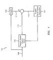
- FIG. 1 Shown in FIG. 1 is an early on-board engine model system 101 used for performance tracking.
- the major components include the monitored engine 103, a physics-based engine model 105 and a performance estimation module 107.
- the physics-based engine model 105 is typically an SVM and the performance estimation module 107 is a Kalman filter observer.
- the engine model 101 is driven by a set of input parameters 109 that command the engine 103.
- the input parameters comprise flight parameters such as Mach number, altitude, ambient conditions and others, and power setting parameters such as fuel flow, engine bleed air commands, variable geometry vane commands and others.
- the monitored engine output parameters 111 comprise gas path parameters such as internal shaft speeds, compressor, combustor and turbine temperatures and pressures and others.
- the physics-based engine model 105 outputs estimated parameters 113 corresponding to each engine 103 output parameter 111.
- the estimated parameters 113 may be used for a variety of purposes.
- the parameters 113 provide for analytical redundancy if a channel mismatch were to occur, for example, in a multichannel redundant system such as a Full Authority Digital Engine Control (FADEC) (not shown), serving as an auctioneer between two redundant signals that have different values.
- FADEC Full Authority Digital Engine Control
- the physics-based engine model 105 estimated output parameters 113 are compared with the engine output parameters 111 to form residuals 115. If the physics-based engine model 105 is an accurate representation of the monitored engine 103, the residuals 115 should be close to zero on the average. However, as engine performance deteriorates over time, the residuals 115 deviate from zero.
- the performance estimator 107 uses the residuals 115 to observe changes in performance across the engine's modules, in the form of adiabatic efficiencies, flow capacities, and turbine nozzle area deltas. This type of analysis is referred to as Gas Path Analysis (GPA) or Module Performance Analysis (MPA).
- GPS Gas Path Analysis
- MPA Module Performance Analysis
- the disparities between the physics-based engine model 105 and engine 103 outputs are used to modify the performance output of the engine model 105 estimated outputs 113 to drive the residuals 115 to zero (on the average). In this manner, the physics-based engine model 105 estimated outputs 113 more accurately reflecting the current state of the engine 103 and the module performance deltas can be tracked over time to aid in determining proper engine work scope when the engine is removed for maintenance.
- the model 101 described above represents an ideal situation where the physics-based engine model 105 is a faithful representation of the engine 103 being monitored. However, the physics-based engine model 105 does not hold true over time. Engine-to-engine variations, models simplified in order to run real-time and deviations caused by improvements to the engine's hardware, bleed and stator vane schedules, cooling flows, handling bleeds.and others, over the engine's life cycle are not reflected in the model 105 and contribute to output disparities between the physics-based engine model 105 and engine 103. The disparities result in inaccurate and misleading estimations in the module performance tracking for the system 101.
- hybrid engine model incorporates both physics-based and empirical components.
- the hybrid architecture automatically modifies a derived engine model to a particular configuration as an engine's characteristics change over its service life and conforms the model to the engine to insure accurate performance tracking.
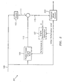
- FIGs. 2 and 3 show hybrid gas turbine engine modeling configurations.
- the hybrid system 201 shown in FIG. 2 derives an empirical model (EM) 203.
- the EM 203 represents the differences, or residuals 115, between measured engine output parameters 111 and the physics-based model output parameters 113.
- the engine 103, the physics-based engine model 105 and the EM 203 are driven by the same input parameters 109.
- the input parameters 109 may vary depending on engine type and application.
- An engine performance estimation 107 is used to track engine performance deviations for engine health diagnostic and prognostic purposes. This typically takes the form of a gas path analysis that estimates performance changes in the major modules of the engine on the basis of residual changes in parameters observed in the engine's gas path, such as temperatures, pressures, speeds, and others.
- the performance changes are usually given in terms of thermodynamic parameters, such as changes in adiabatic efficiency and flow capacity for the compression modules, and changes in adiabatic efficiency and nozzle area for the turbine modules. Since the residual gas path data is used in this determination, the reference (from which the changes are estimated) is the engine model under consideration.
- the EM 203 may use relationship models such as regression, autoregressive moving average (ARMA), artificial neural network (ANN), and others for prediction.
- the hybrid model 301 includes a physics-based engine model 105 and an EM 203 that models the difference between the physics-based engine model 105 and the engine 103 being monitored.
- the addition 305 of the physics-based engine model 105 and EM 203 outputs produces a hybrid model 303 representation of the monitored engine 103 as it appeared during the period of operation when residual data was gathered and processed to form the empirical element.
- a Kalman filter observer 107 is provided to perform the gas path analysis to monitor the engine's health 307 after the empirical model 203 is available.
- the system identification methods shown in FIGs. 2 and 3 should be performed on board in real-time during engine operation and flight to negate the need for establishing a data infrastructure to capture, store and transfer the requisite data for modeling to a ground computer for developing the empirical model element. Otherwise, the system 301 shown in FIG. 3 would require the storage and retention of engine and flight input data over a series of flights until a sufficient amount of flight and engine regime data was accumulated to complete the EM 203. This would impose an unrealistic storage capacity requirement for the system.
- one methodology incrementally builds an EM using a flight envelope partition to create smaller EM sub-models.
- An example of a flight envelope partition is shown in FIG. 4.
- the flight envelope is given in terms of altitude and Mach number and defines the flight regime for which the engine under consideration is equipped to operate.
- the partition is simply a subdivision of this region into smaller regions referred to as cells 401. These regions are typically taken to be rectangular areas and are characterized by their height (altitude) and width (Mach) and a center coordinate 403. Data collected within a given cell is used to generate an empirical sub-model that represents the difference between the physics-based engine model estimated parameters and the actual engine's measured parameters in that region of the flight envelope. These empirical sub-models are incrementally assembled as flight data becomes available in a given cell.
- the partitioning of the flight envelope contributes to the concept of sequential modeling in that it allows the construction of a series of sub-models to represent the model space. Since the flight envelope grid is predefined in order to limit the number of sub-models, it is likely that insufficient data within a given grid element would be collected during a single flight to properly model that subspace. No matter what particular modeling methodology is used, the entire set of data would have to be maintained for the proper modeling of the given sub-region. Extending this process across the entire partitioned flight envelope would require storing an enormous amount of data that would be impractical and prohibitive.
- the inventors have discovered that it would be desirable to have methods and systems that model gas turbine engines using empirical sub-models as tuning elements.
- the methods and systems involve sequentially developing and storing a compact statistical and parametric representation of flight data collected in real-time. During an off-line process, the data may be used to generate a statistically representative set of pseudo-data samples that are used to update an empirical engine model.
- the invention preferably provides a computation and storage reduction in excess of 1000:1 over previous methodologies.
- One aspect of the invention provides methods for training a multi-layer network used in conjunction with a physics-based engine model to define a hybrid model for modeling a gas turbine engine used for flight.
- Methods according to this aspect of the invention preferably start with inputting an input signal to the gas turbine engine for operational control and to the physics-based engine model, wherein the input signal comprises a plurality of parameters, combining output parameters from the gas turbine engine with corresponding parameters estimated by the physics-based engine model to form a residual for each parameter, the gas turbine output parameters and physics-based engine model estimated parameters are responsive to the input signal parameters, deriving a mean and a standard deviation for each parameter of a first predetermined number of the input signals, deriving a mean and a standard deviation for residuals responsive to the first predetermined number of the input signals, associating a mean Mach and a mean altitude, wherein the Mach and altitude are input signal parameters, with one of a plurality of flight envelope cells, wherein if a parameter of the input signal or a responsive residual
- the method compares each independent input signal parameter from the input signal with pre-existing statistical distributions within the associated cell, wherein if an independent parameter of the input signal is included in a pre-existing statistical distribution, the pre-existing distribution is used for training the multi-layer network, and if an independent parameter of the input signal is not included in a pre-existing statistical distribution, a new statistical distribution is created for each input signal parameter from the input signal.
- the invention is not limited to any particular software language described or implied in the figures. A variety of alternative software languages may be used for implementation of the invention. Some components and items are illustrated and described as if they were hardware elements, as is common practice within the art. However, various components in the method and system may be implemented in software or hardware.
- the invention is preferably a modular framework and is preferably deployed as software as an application program tangibly embodied on a program storage device.
- the application code for execution can reside on a plurality of different types of computer readable media known to those skilled in the art.
- Embodiments of the invention provide methods and systems that derive high fidelity models for gas turbine engines.
- the models are capable of providing a reference level from which actual engine performance changes may be trended with increased reliability and speed, and reduced operating cost and computational expense.
- the preferred embodiments comprise methods and systems that implement a two-stage empirical modeling process for a gas turbine engine.
- the first stage is executed in real-time during flight operation and performs a flight data reduction to encapsulate a reduced order representation of input and residual parameter differences that are modeled during the second stage.
- the reduction is accomplished in real-time using a sequential clustering process that leverages the continuous nature of flight data to reduce processing time and memory resources to create a plurality of Gaussian Mixture Models (GMM).
- GMM Gaussian Mixture Models
- the second stage may be performed in real-time or off-line, usually at the end of a flight, after the first stage processing has been completed.
- the second stage uses the GMM representations of the data accumulated during the first stage processing.
- the GMM data that accumulates comprises the last flight and all previous flights.
- the data is used to derive an EM that is used in conjunction with a physics-based engine model to provide a high fidelity hybrid engine model.
- the physics-based engine model is used to produce residuals' during the first stage.
- the system 501 is used in conjunction with an actual gas turbine engine 103 that is the subject to be modeled and comprises a physics-based engine model 105, a GMM clustering engine 503, a GMM data store 505, an MLP training engine 507 and an MLP data store 509.
- the first stage 511 method uses the physics-based engine model 105, GMM clustering engine 503 and GMM data store 505.
- the second stage 513 method uses the MLP training engine 507 and MLP data store 509 to add to and refine an EM model 203 used in a hybrid engine model 301.
- Input signals 109 are coupled to the engine 103 for control and to the physics-based engine model 105 and GMM clustering engine 503.
- the inputs signals 109 represent a plurality of independent parameters.
- the independent parameters comprise flight conditions such as altitude and Mach, engine power descriptors such as corrected spool speed, engine bleed air commands and variable geometry vane commands, and other information such as weight on wheels to indicate when an aircraft has landed 504.
- Engine 103 outputs 111 represent a plurality of measured gas path parameters such as temperatures, pressures, speeds, flows, and others.
- the input signals 109 command the physics-based engine model 105 which models engine 103 behavior contemporaneous with actual engine 103 behavior. Both the engine 103 and physics-based engine model 105 output the same number of different gas path parameters.
- the engine 103 outputs 111 and physics-based engine model 105 output estimates 113 are coupled to a summer 502 to produce residuals 501.
- the residuals 501 represent differences between the outputs, actual 111 versus estimated 113, indicating the accuracy of the physics-based engine model 105.
- the residuals 501 are coupled to the GMM clustering engine 503.
- a flight envelope partition as shown in FIG. 4 is employed.
- the flight envelope partition reduces the amount of memory resources and computational expense by dividing the empirical modeling task into separate sub-models.
- the flight envelope partition divides an operational flight envelope into n cells 401 that become the sub-model domains. To determine which cell 401 is active and which cell flight data belongs to, each cell 401 may have equal dimensions. For example, a 0.2 Mach width by 10,000 ft height. An altitude and Mach number coordinate pair identifies the center 403 of each cell.
- the flight envelope partition is known a priori and may be stored in the MLP data store 507 as a look-up table (LUT).
- the GMM clustering engine'503 is coupled to the GMM data store 505.
- the GMM data store 505 holds data output by the GMM clustering engine 503 that relates to the reduced order encapsulation of the physics-based engine model 105 and residuals 501.
- the GMM data store 505 is coupled to the MLP training engine 507.
- the GMM data 505 acquired during flight is used by the MLP training engine 507 during the second stage 513 off-line process to create new, and update previous EM sub-models.
- the data is stored as a multi-layer network.
- This class of networks consists of multiple layers of computational units, usually interconnected in a feed-forward manner. Each neuron in one layer has directed connections to the neurons of the subsequent layer.
- the first 511 and second 513 stages operate on a flight envelope cell-by-cell basis. Residuals 501 derived during flight are associated with a respective flight envelope cell 401 via Mach and altitude.
- a GMM created by the GMM clustering engine 503 is stored in the GMM data store 505 and is subsequently used to construct EM sub-models during the second stage 513.
- the data is stored as a series of multi-layer perceptron (MLP) neural networks.
- the EM 203 used in a hybrid model 303 is updated with the series of MLPs.
- the MLP data store 509 holds sub-models for each flight envelope cell 401.
- the EM 203 is derived incrementally during the second stage 513.
- Models such as high order statistical regression, neural networks, support vector machines and others may be used.
- This class of neural networks consists of multiple layers of computational units known as universal approximators. They are referred to as feed-forward, back propagation artificial neural networks and are employed for functional approximation in numerous engineering applications. They are defined by a series of layers consisting of an input layer, a hidden layer, and an output layer. Each layer consists of a number of neurons which perform an arithmetical operation.
- the number of neurons in the input layer is equal to the number of input signal parameters 109, the number of hidden layer neurons is fixed by a user (25 has been found to be adequate), and the number of output layer neurons may be equal to 1.
- the single neuron computes the estimate of a single residual parameter. This means that an MLP is created and updated for each residual parameter.
- the system may be configured to have the number of output layer neurons equal the number of residual parameters, thereby requiring one MLP per cell, however, this configuration would require a much larger hidden layer, in excess of 25.
- the GMMs 503 created by the clustering engine 503 are multi-dimensional Gaussian distributions characterized by two statistical vectors, a mean, and a measure of dispersion or standard deviation.
- the sample size from which the statistical quantities are computed is also stored with a GMM.
- the mean and standard deviation vectors contain the input signal parameters 109 as well as the residual parameters 501.
- the residual vector 501 r is determined as the difference between each measured engine output 111 y and its corresponding physics-based engine model 105 output estimate 113.
- the engine 103 signal inputs 109 u may include altitude, Mach number, fuel flow demand, engine bleed air commands, active clearance control commands, variable geometry vane commands, as well as other engine input parameters.
- the engine 103 outputs 111 y and residuals 501 r may include engine speeds, interstage temperatures and pressures, flows, and others.
- a GMM created by the clustering engine 503 may comprise means and standard deviation vectors pertaining to the signal inputs 109 and residuals 501 that are computed recursively during GMM clustering 503.
- the mean u N and standard deviation ⁇ N u vectors for the signal inputs 109 and the mean r N and standard deviation ⁇ N r vectors for the residuals 501 are computed recursively to minimize computation time and memory expense.
- u N and ⁇ N u represent m c ⁇ 1 vectors of (running) input 109 means and standard deviations
- r N and ⁇ N r represent m r ⁇ 1 vectors of residual 501 means and standard deviations after N data points have been processed. Since an input signal is comprised of a plurality of individual parameters in discrete time, a data point is defined as one input signal vector and one residual vector comprising all input parameters and residual parameters at time t , at a frequency in a range of about 5-50 Hz,.
- the mean u N , r N and standard deviation ⁇ N u , ⁇ N r vectors with their respective sample sizes N at termination are stored in the GMM data store 505.
- FIG. 6 Shown in FIG. 6 is a method overview showing the data flow for the hybrid model training system 501 as an EM 203 is created incrementally.
- the GMM clustering engine 503 continuously processes input signal data 109 and derived residuals 501 as an aircraft transcends a trajectory through the flight envelope cells 401.
- the method determines whether a flight has terminated (steps 605 and 610) by monitoring a number of aircraft parameters such as weight-on-wheels 504. If a flight is in progress, the system 501 monitors input signal data 109 and derived residuals 501, performs clustering 503 and stores the GMMs 505. When the flight ends, the system 501 stops acquiring data 109, 501 and performs an EM update 203 (step 615) by re-evaluating the MLP sub-models in the MLP data store 509 (steps 615, 620).
- vectors u N and r N are normalized (step 625) to reduce variability in the data. Normalization applies standard corrections such as gas path standard day corrections to remove the effects of ambient temperature and pressure, and flight condition, as well as to reduce the complexity of the empirical modeling effort.
- a GMM is defined and any existing GMM models that are present in the GMM data store 509 for that respective cell are loaded (step 635).
- the hybrid model 303 is executed in a frozen state (step 650).
- a frozen state is where the last known performance ⁇ estimate, produced as output from 107, is held constant.
- the performance ⁇ s are typically given as changes in engine module adiabatic efficiencies, flow capacities, and turbine nozzle areas.
- the GMM clustering engine 503 (step 655) will create a new GMM element from the residual data.
- the initiation and determination of a new GMM element uses a method that includes an exit criterion to determine when to stop the GMM building process. Since a GMM represents a multi-dimensional cluster, representing all parameters, the method needs to determine when to exit the cluster building calculation.
- the criterion depends on the number of data points collected to represent the current GMM cluster, which itself depends on certain stability calculations as well as a distance migration from cluster initiation.
- N MIN a minimum number of data points, N MIN , is required.
- N MIN depends on whether the data is acquired during steady state operation, where the input parameters are not migrating (altitude and Mach constant), or in a transient condition where the aircraft is in a climb or a decent.
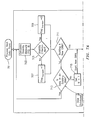
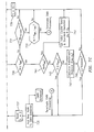
- the clustering method begins where the current data point (step 701) is examined to determine if it was acquired during a steady state or transient condition.
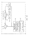
- a stability metric is computed (step 703) as shown in FIG. 8.
- the stability metric determines whether or not the aircraft is climbing or descending. The metric indicates if the flight condition is changing rapidly which impacts the choice of N MIN . If the flight condition is stable, N MIN may be larger than if the flight condition is varying quickly. N MIN insures that more GMMs are created (per data quantity) during a transient for better resolution.
- the stability metric trends (steps 801 and 803) the incoming data over a predefined number of data points (step 805).
- a time period is preselected to serve as a time base for measuring a rate of change of data N (step 807).
- a change in rate is calculated, for example, using altitude as one input parameter (steps 809 and 811).
- the derivative, ⁇ n may be an averaged rate of change of altitude computed from altitude data, or a complex measure that takes into account other flight and engine power parameters as necessary (step 813).
- the averaged derivative, ⁇ n is compared with a predefined limit (step 815) to determine whether the aircraft is within a margin that identifies either steady state (step 817) or transient behavior (steps 819 and 821).
- the method determines if a new GMM cluster is in progress (step 711). If the method is not creating a new GMM for a current data point N , the method determines if the current data point belongs to an existing GMM (step 713).
- the method computes a Euclidean distance measured from the current data point to each GMM in the database. The minimum distance is compared to a threshold. If the threshold is exceeded, the current data point is not included in an existing GMM, otherwise it is included in at least one database 505 GMM.
- the distance calculation only involves independent parameters, i.e. the inputs in the current data point and the GMMs that the data points are being compared with in the database.
- the distance metric may be computed in a plurality of ways.
- c u M and s u M are the mean and standard deviation vector, respectively, of the inputs of the M th GMM in the database
- u N is the input vector associated with the current N th data point
- ⁇ is a pre-specified normalizing vector of constants.
- the current N th data point is included in an existing GMM and the hybrid model may be run in the frozen mode described above. If the threshold is exceeded, the current data point is the first data point in the generation of a new GMM cluster and the counter N is set to 1 (step 715).
- N MIN_SS a minimum number specification for steady state N MIN_SS
- N MIN_Trans a minimum number specification for transient N MIN_Trans if the transient flag was set to a 0 or a 1.
- This test examines the rate of change of inputs, for example altitude, and determines if the rate exceeds a predefined limit. If the rate exceeds the predefined limit, N MIN takes the value of N MIN_Trans . If the rate does not exceed the predefined limit, N MIN takes the value of N MIN_SS .
- the method recursively updates the averages and standard deviations of the input 109 and residual 501 parameters of the GMM cluster that is currently in formation (step 725).
- the initial GMM cluster mean and standard deviation vectors ⁇ 0 and ⁇ 0 for the input vector u are determined (step 743) and are temporarily stored for reference.
- the statistics are updated for each incoming data point until an exit criterion is satisfied to end the GMM clustering process and establish a new GMM cluster point for the database.
- the method provides two exit criteria.
- N represents the current number of data points in the current GMM cluster which is being formed
- the method ends when one of two conditions are met, i.e. , either N is larger than a predefined maximum N MAX , ( N ⁇ N MAX ) (step 745) or the running average u ⁇ N ⁇ has migrated sufficiently far from the initial average ⁇ 0 .
- the latter condition is tested by calculating a Mahalanobis vector distance d ⁇ 0 ⁇ u ⁇ N ⁇ (step 747) and comparing it to a predefined threshold (step 749).
- the clustering process ends if either condition d ⁇ 0 ⁇ u ⁇ N ⁇ ⁇ Threshold , or N ⁇ N MAX is satisfied.
- the newly formed GMM is added to the database (step 749) and the next data point received follows the same overall process to determine if it is within the domain of an existing GMM and if not, a new GMM formation is initiated.
- the newly formed GMM includes a vector of averages for the input and residual parameters, a vector of standard deviations for the input and residual parameters, and a sample size associated with those statistical calculations (equations 1-4).
- Shown in FIG. 9 is a partial cell of a flight envelope cell depicting GMM and sample data locations.
- the small dots represent the location in terms of altitude and Mach for the sample data.
- only two input parameters are shown plotted for convenience.
- the large dots represent the locations of the GMM centers (averages) and the ellipses represent the GMM 1-sigma standard deviations about those centers. It may be evident that 3-sigma ellipses would encompass all of the small dots.
- the GMMs form a compressed representation of the data and cover the data.
- a data point When a data point is determined to be within the domain of an existing GMM, it is processed by the (existing) hybrid model 303 using current MLP empirical model elements. Since the data point is already represented by an existing GMM, an existing MLP empirical model provides the requisite compensation to allow performance estimation to be determined without corruption. If the data point is not within the domain of an existing GMM, the hybrid model is run in frozen mode and a new GMM cluster process is initiated for the data point as described above.
- Frozen mode processes the data point as indicated in FIG. 2 where the initial performance level input to the Kalman filter is frozen at the last known value estimated (from data within the current GMM database domain). Maintaining the value at the last known value estimate insures that the residuals used in the GMM cluster formation do not contain presently known deterioration effects.
- This mode only views (empirically) the differences between the engine 103 and physics-based model 105 and does not capture any deterioration that might have accrued since commencing engine 103 operation.
- the second stage 513 of the invention is initiated.
- the GMM database 505 is examined for newly generated clusters on a cell-by-cell basis. If a given cell 401 is found to have newly generated GMMs, the entire collection of GMMs for that cell are used to generate a new MLP empirical model for each of the residual measurements.
- the collection of GMMs within a cell contain a compact representation of flight data that occurred within that cell in the form of input parameter and residual parameter averages, means and standard deviations, and associated sample sizes. This compact data representation can be modeled using an MLP.
- the second stage 513 modeling process may be performed off-line after flight termination, and the subsequent MLPs generated are stored in the empirical model data store 509 replacing and updating the previously stored MLPs.
- the MLPs in the data store 509 constitute the empirical model element 203 in the hybrid model 303 for subsequent analysis of future flight data.
Landscapes
- Physics & Mathematics (AREA)
- General Physics & Mathematics (AREA)
- Engineering & Computer Science (AREA)
- Automation & Control Theory (AREA)
- Feedback Control In General (AREA)
- Engine Equipment That Uses Special Cycles (AREA)
- Complex Calculations (AREA)
Applications Claiming Priority (1)
| Application Number | Priority Date | Filing Date | Title |
|---|---|---|---|
| US11/540,874 US7472100B2 (en) | 2006-09-29 | 2006-09-29 | Empirical tuning of an on board real-time gas turbine engine model |
Publications (2)
| Publication Number | Publication Date |
|---|---|
| EP1906291A1 true EP1906291A1 (de) | 2008-04-02 |
| EP1906291B1 EP1906291B1 (de) | 2010-09-08 |
Family
ID=38720347
Family Applications (1)
| Application Number | Title | Priority Date | Filing Date |
|---|---|---|---|
| EP07252989A Ceased EP1906291B1 (de) | 2006-09-29 | 2007-07-30 | Empirische Einstellung eines Echtzeit-Gasturbinenmotorenmodells |
Country Status (5)
| Country | Link |
|---|---|
| US (1) | US7472100B2 (de) |
| EP (1) | EP1906291B1 (de) |
| CA (1) | CA2595098C (de) |
| DE (1) | DE602007009006D1 (de) |
| SG (1) | SG141305A1 (de) |
Cited By (4)
| Publication number | Priority date | Publication date | Assignee | Title |
|---|---|---|---|---|
| EP2336918A1 (de) * | 2009-12-21 | 2011-06-22 | United Technologies Corporation | Verfahren und System zur Modellierung der Leistung einer Gasturbine |
| CN105868467A (zh) * | 2016-03-28 | 2016-08-17 | 南京航空航天大学 | 一种动稳态航空发动机机载模型构建方法 |
| EP3451085A1 (de) * | 2017-08-28 | 2019-03-06 | United Technologies Corporation | Verfahren zur auswahl optimaler motorbetriebsbedingungen zur erzeugung linearisierter modelle für bordsteuerung und schätzung |
| CN114280608A (zh) * | 2022-03-07 | 2022-04-05 | 成都理工大学 | 一种DInSAR高程相关大气效应去除方法及系统 |
Families Citing this family (29)
| Publication number | Priority date | Publication date | Assignee | Title |
|---|---|---|---|---|
| US7680751B2 (en) * | 2006-05-31 | 2010-03-16 | Honeywell International Inc. | Neural network based refrigerant charge detection algorithm for vapor compression systems |
| US20090048730A1 (en) * | 2007-08-17 | 2009-02-19 | General Electric Company | Method and system for planning repair of an engine |
| US20100017092A1 (en) * | 2008-07-16 | 2010-01-21 | Steven Wayne Butler | Hybrid fault isolation system utilizing both model-based and empirical components |
| US7861578B2 (en) * | 2008-07-29 | 2011-01-04 | General Electric Company | Methods and systems for estimating operating parameters of an engine |
| US8131384B2 (en) * | 2008-11-03 | 2012-03-06 | United Technologies Corporation | Design and control of engineering systems utilizing component-level dynamic mathematical model with multiple-input multiple-output estimator |
| US8090456B2 (en) * | 2008-11-03 | 2012-01-03 | United Technologies Corporation | System and method for design and control of engineering systems utilizing component-level dynamic mathematical model |
| US8321118B2 (en) * | 2008-12-23 | 2012-11-27 | Honeywell International Inc. | Operations support systems and methods with power assurance |
| US7801695B2 (en) * | 2008-12-23 | 2010-09-21 | Honeywell International Inc. | Operations support systems and methods with model-based torque estimates |
| US8306778B2 (en) * | 2008-12-23 | 2012-11-06 | Embraer S.A. | Prognostics and health monitoring for electro-mechanical systems and components |
| US8417410B2 (en) * | 2008-12-23 | 2013-04-09 | Honeywell International Inc. | Operations support systems and methods with power management |
| US20100161196A1 (en) * | 2008-12-23 | 2010-06-24 | Honeywell International Inc. | Operations support systems and methods with engine diagnostics |
| US7881880B2 (en) * | 2009-04-01 | 2011-02-01 | United Technologies Corporation | Actuator performance monitoring system |
| US9618919B2 (en) * | 2009-05-28 | 2017-04-11 | General Electric Company | Real-time scheduling of linear models for control and estimation |
| US8315741B2 (en) * | 2009-09-02 | 2012-11-20 | United Technologies Corporation | High fidelity integrated heat transfer and clearance in component-level dynamic turbine system control |
| US8668434B2 (en) * | 2009-09-02 | 2014-03-11 | United Technologies Corporation | Robust flow parameter model for component-level dynamic turbine system control |
| US9342060B2 (en) | 2010-09-14 | 2016-05-17 | United Technologies Corporation | Adaptive control for a gas turbine engine |
| US8682454B2 (en) | 2011-02-28 | 2014-03-25 | United Technologies Corporation | Method and system for controlling a multivariable system with limits |
| US20130024179A1 (en) * | 2011-07-22 | 2013-01-24 | General Electric Company | Model-based approach for personalized equipment degradation forecasting |
| FR2993375B1 (fr) * | 2012-07-10 | 2014-07-18 | Snecma | Methode de detection d'une degradation d'une turbomachine par surveillance des performances de ladite turbomachine |
| US20140222310A1 (en) * | 2012-10-09 | 2014-08-07 | United Technologies Corporation | Engine monitor for a multi-engine system |
| US20140182297A1 (en) * | 2013-01-03 | 2014-07-03 | General Electric Company | Gas turbine and method of controlling a gas turbine at part-load condition |
| US9869305B1 (en) * | 2013-03-14 | 2018-01-16 | Tucson Embedded Systems, Inc. | Pump-engine controller |
| US10151643B2 (en) * | 2016-08-22 | 2018-12-11 | The Boeing Company | Thermal event indicator for aircraft engine |
| US11144683B2 (en) | 2016-12-06 | 2021-10-12 | General Electric Company | Real-time adaptation of system high fidelity model in feature space |
| US10474113B2 (en) | 2017-03-09 | 2019-11-12 | General Electric Company | Power generation system control through adaptive learning |
| US11085321B2 (en) | 2018-01-30 | 2021-08-10 | Honeywell International Inc. | Bleed air compensated continuous power assurance analysis system and method |
| FR3133885A1 (fr) * | 2022-03-28 | 2023-09-29 | Safran | Procédé de surveillance de l’état de santé de turbomachine d’aéronef |
| FR3133884B1 (fr) * | 2022-03-28 | 2025-11-21 | Safran | Procédé de surveillance de l’état de santé de turbomachine d’aéronef |
| CN118883069B (zh) * | 2024-08-14 | 2025-09-05 | 中国航发湖南动力机械研究所 | 涡轴发动机稳态性能点提取方法、装置、设备及存储介质 |
Citations (3)
| Publication number | Priority date | Publication date | Assignee | Title |
|---|---|---|---|---|
| EP1357487A2 (de) * | 2002-04-23 | 2003-10-29 | United Technologies Corporation | Verfahren und Vorrichtung zur Entwicklung eines hybriden Gasturbinenmodells auf der Basis von Zustandsvariablen |
| EP1637944A2 (de) | 2004-08-26 | 2006-03-22 | United Technologies Corporation | Bootstrap-Datenmethodologie zum Bilden von aufeinander folgenden Hybridmodellen |
| EP1643332A2 (de) * | 2004-10-04 | 2006-04-05 | United Technologies Corporation | System zur Fehlererkennung und Isolierung basiert auf einem hybriden Modell |
Family Cites Families (6)
| Publication number | Priority date | Publication date | Assignee | Title |
|---|---|---|---|---|
| US5481648A (en) * | 1993-12-23 | 1996-01-02 | United Technologies Corp. | Fuzzy logic method and apparatus for changing the position of turbine blades via an induction motor, brake and a position lock. |
| US6289274B1 (en) * | 1999-08-13 | 2001-09-11 | United Technologies Corporation | Fuzzy logic based fuel flow selection system |
| US6466858B1 (en) * | 2000-11-02 | 2002-10-15 | General Electric Company | Methods and apparatus for monitoring gas turbine engine operation |
| US6909960B2 (en) * | 2002-10-31 | 2005-06-21 | United Technologies Corporation | Method for performing gas turbine performance diagnostics |
| US7136809B2 (en) * | 2002-10-31 | 2006-11-14 | United Technologies Corporation | Method for performing an empirical test for the presence of bi-modal data |
| US7233884B2 (en) * | 2002-10-31 | 2007-06-19 | United Technologies Corporation | Methodology for temporal fault event isolation and identification |
-
2006
- 2006-09-29 US US11/540,874 patent/US7472100B2/en active Active
-
2007
- 2007-07-13 SG SG200705268-1A patent/SG141305A1/en unknown
- 2007-07-26 CA CA2595098A patent/CA2595098C/en not_active Expired - Fee Related
- 2007-07-30 DE DE602007009006T patent/DE602007009006D1/de active Active
- 2007-07-30 EP EP07252989A patent/EP1906291B1/de not_active Ceased
Patent Citations (3)
| Publication number | Priority date | Publication date | Assignee | Title |
|---|---|---|---|---|
| EP1357487A2 (de) * | 2002-04-23 | 2003-10-29 | United Technologies Corporation | Verfahren und Vorrichtung zur Entwicklung eines hybriden Gasturbinenmodells auf der Basis von Zustandsvariablen |
| EP1637944A2 (de) | 2004-08-26 | 2006-03-22 | United Technologies Corporation | Bootstrap-Datenmethodologie zum Bilden von aufeinander folgenden Hybridmodellen |
| EP1643332A2 (de) * | 2004-10-04 | 2006-04-05 | United Technologies Corporation | System zur Fehlererkennung und Isolierung basiert auf einem hybriden Modell |
Non-Patent Citations (3)
| Title |
|---|
| SIMANI S ET AL: "Fault diagnosis of non-linear dynamic processes using identified hybrid models", 42ND. IEEE CONFERENCE ON DECISION AND CONTROL.(CDC). MAUI, HI, DEC. 9, vol. VOL. 1 OF 6. CONF. 42, 9 December 2003 (2003-12-09), pages 445 - 450, XP010686227, ISBN: 0-7803-7924-1 * |
| SIMANI S: "Hybrid model identification for fault diagnosis of non-linear dynamic processes", AMERICAN CONTROL CONFERENCE, 2004. PROCEEDINGS OF THE 2004 BOSTON, MA, USA JUNE 30-JULY 2, 2004, PISCATAWAY, NJ, USA,IEEE, vol. 3, 30 June 2004 (2004-06-30), pages 2445 - 2450, XP010761190, ISBN: 0-7803-8335-4 * |
| VOLPONI A ET AL: "A Bootstrap Data Methodology for Sequential Hybrid Engine Model Building", AEROSPACE, 2005 IEEE CONFERENCE BIG SKY, MT, USA 05-12 MARCH 2005, PISCATAWAY, NJ, USA,IEEE, 5 March 2005 (2005-03-05), pages 1 - 9, XP010864586, ISBN: 0-7803-8870-4 * |
Cited By (7)
| Publication number | Priority date | Publication date | Assignee | Title |
|---|---|---|---|---|
| EP2336918A1 (de) * | 2009-12-21 | 2011-06-22 | United Technologies Corporation | Verfahren und System zur Modellierung der Leistung einer Gasturbine |
| CN105868467A (zh) * | 2016-03-28 | 2016-08-17 | 南京航空航天大学 | 一种动稳态航空发动机机载模型构建方法 |
| CN105868467B (zh) * | 2016-03-28 | 2018-09-07 | 南京航空航天大学 | 一种动稳态航空发动机机载模型构建方法 |
| EP3451085A1 (de) * | 2017-08-28 | 2019-03-06 | United Technologies Corporation | Verfahren zur auswahl optimaler motorbetriebsbedingungen zur erzeugung linearisierter modelle für bordsteuerung und schätzung |
| US10378455B2 (en) | 2017-08-28 | 2019-08-13 | United Technologies Corporation | Method for selection of optimal engine operating conditions for generating linearized models for on-board control and estimation |
| CN114280608A (zh) * | 2022-03-07 | 2022-04-05 | 成都理工大学 | 一种DInSAR高程相关大气效应去除方法及系统 |
| CN114280608B (zh) * | 2022-03-07 | 2022-06-17 | 成都理工大学 | 一种DInSAR高程相关大气效应去除方法及系统 |
Also Published As
| Publication number | Publication date |
|---|---|
| DE602007009006D1 (de) | 2010-10-21 |
| US20080154823A1 (en) | 2008-06-26 |
| CA2595098C (en) | 2011-03-01 |
| EP1906291B1 (de) | 2010-09-08 |
| CA2595098A1 (en) | 2008-03-29 |
| SG141305A1 (en) | 2008-04-28 |
| US7472100B2 (en) | 2008-12-30 |
Similar Documents
| Publication | Publication Date | Title |
|---|---|---|
| EP1906291B1 (de) | Empirische Einstellung eines Echtzeit-Gasturbinenmotorenmodells | |
| US10814883B1 (en) | Prognostics for improved maintenance of vehicles | |
| US11436395B2 (en) | Method for prediction of key performance parameter of an aero-engine transition state acceleration process based on space reconstruction | |
| EP1777157B1 (de) | System und Verfahren zur Schädigungsvorhersage einer Vorrichtung | |
| US6909960B2 (en) | Method for performing gas turbine performance diagnostics | |
| EP2141560A2 (de) | System und Verfahren zur Vorhersage von Systemereignissen und Verschlechterung | |
| Saxena et al. | Damage propagation modeling for aircraft engine run-to-failure simulation | |
| US7904282B2 (en) | Method and system for fault accommodation of machines | |
| CN108733868B (zh) | 用于基于飞行数据的参数调谐和配置的方法和系统 | |
| CN109102101B (zh) | 风电场风速的预测方法和系统 | |
| US8849542B2 (en) | Real time linearization of a component-level gas turbine engine model for model-based control | |
| US20090048730A1 (en) | Method and system for planning repair of an engine | |
| US20110153295A1 (en) | Method and system for modeling the performance of a gas turbine engine | |
| US10127257B2 (en) | Methods of creating a database and of formulating a map of operating states of aircraft and a method of monitoring the operation of an associated aircraft | |
| US10486833B2 (en) | Method for monitoring an aircraft engine operating in a given environment | |
| US20220076581A1 (en) | Computing environment system for monitoring aircraft engines | |
| EP4111270B1 (de) | Prognose für verbesserte wartung von fahrzeugen | |
| JP2019021032A (ja) | シミュレーション装置およびシミュレーション方法 | |
| Armstrong et al. | Implementation of an integrated on-board aircraft engine diagnostic architecture | |
| Tang et al. | Extending engine gas path analysis using full flight data | |
| Volponi | Use of hybrid engine modeling for on-board module performance tracking | |
| US9482597B2 (en) | Method and a device for normalizing values of operating parameters of an aeroengine | |
| Fu et al. | A prognostic approach to improve system reliability for aircraft system | |
| US12552551B2 (en) | Method for determining an efficiency fault of an aircraft turboshaft engine module | |
| Volponi et al. | A bootstrap data methodology for sequential hybrid engine model building |
Legal Events
| Date | Code | Title | Description |
|---|---|---|---|
| PUAI | Public reference made under article 153(3) epc to a published international application that has entered the european phase |
Free format text: ORIGINAL CODE: 0009012 |
|
| AK | Designated contracting states |
Kind code of ref document: A1 Designated state(s): AT BE BG CH CY CZ DE DK EE ES FI FR GB GR HU IE IS IT LI LT LU LV MC MT NL PL PT RO SE SI SK TR |
|
| AX | Request for extension of the european patent |
Extension state: AL BA HR MK YU |
|
| 17P | Request for examination filed |
Effective date: 20080523 |
|
| 17Q | First examination report despatched |
Effective date: 20080623 |
|
| AKX | Designation fees paid |
Designated state(s): DE GB |
|
| GRAP | Despatch of communication of intention to grant a patent |
Free format text: ORIGINAL CODE: EPIDOSNIGR1 |
|
| GRAS | Grant fee paid |
Free format text: ORIGINAL CODE: EPIDOSNIGR3 |
|
| GRAA | (expected) grant |
Free format text: ORIGINAL CODE: 0009210 |
|
| AK | Designated contracting states |
Kind code of ref document: B1 Designated state(s): DE GB |
|
| REG | Reference to a national code |
Ref country code: GB Ref legal event code: FG4D |
|
| REF | Corresponds to: |
Ref document number: 602007009006 Country of ref document: DE Date of ref document: 20101021 Kind code of ref document: P |
|
| PLBE | No opposition filed within time limit |
Free format text: ORIGINAL CODE: 0009261 |
|
| STAA | Information on the status of an ep patent application or granted ep patent |
Free format text: STATUS: NO OPPOSITION FILED WITHIN TIME LIMIT |
|
| 26N | No opposition filed |
Effective date: 20110609 |
|
| REG | Reference to a national code |
Ref country code: DE Ref legal event code: R097 Ref document number: 602007009006 Country of ref document: DE Effective date: 20110609 |
|
| PGFP | Annual fee paid to national office [announced via postgrant information from national office to epo] |
Ref country code: DE Payment date: 20140724 Year of fee payment: 8 |
|
| PGFP | Annual fee paid to national office [announced via postgrant information from national office to epo] |
Ref country code: GB Payment date: 20140730 Year of fee payment: 8 |
|
| REG | Reference to a national code |
Ref country code: DE Ref legal event code: R119 Ref document number: 602007009006 Country of ref document: DE |
|
| GBPC | Gb: european patent ceased through non-payment of renewal fee |
Effective date: 20150730 |
|
| PG25 | Lapsed in a contracting state [announced via postgrant information from national office to epo] |
Ref country code: GB Free format text: LAPSE BECAUSE OF NON-PAYMENT OF DUE FEES Effective date: 20150730 Ref country code: DE Free format text: LAPSE BECAUSE OF NON-PAYMENT OF DUE FEES Effective date: 20160202 |