EP1906201A1 - Carrier phase interger ambiguity resolution with multiple reference receivers - Google Patents
Carrier phase interger ambiguity resolution with multiple reference receivers Download PDFInfo
- Publication number
- EP1906201A1 EP1906201A1 EP07117206A EP07117206A EP1906201A1 EP 1906201 A1 EP1906201 A1 EP 1906201A1 EP 07117206 A EP07117206 A EP 07117206A EP 07117206 A EP07117206 A EP 07117206A EP 1906201 A1 EP1906201 A1 EP 1906201A1
- Authority
- EP
- European Patent Office
- Prior art keywords
- antenna
- phase
- master
- antennae
- carrier
- Prior art date
- Legal status (The legal status is an assumption and is not a legal conclusion. Google has not performed a legal analysis and makes no representation as to the accuracy of the status listed.)
- Withdrawn
Links
- 238000005259 measurement Methods 0.000 claims abstract description 55
- 238000000034 method Methods 0.000 claims abstract description 33
- 238000012545 processing Methods 0.000 claims description 5
- 238000012795 verification Methods 0.000 claims description 2
- 238000004891 communication Methods 0.000 description 7
- 238000010586 diagram Methods 0.000 description 6
- 238000013459 approach Methods 0.000 description 5
- RYGMFSIKBFXOCR-UHFFFAOYSA-N Copper Chemical compound [Cu] RYGMFSIKBFXOCR-UHFFFAOYSA-N 0.000 description 1
- 230000006978 adaptation Effects 0.000 description 1
- 239000006227 byproduct Substances 0.000 description 1
- 239000000969 carrier Substances 0.000 description 1
- 230000006870 function Effects 0.000 description 1
- 239000013307 optical fiber Substances 0.000 description 1
- 230000004044 response Effects 0.000 description 1
Images


Classifications
-
- G—PHYSICS
- G01—MEASURING; TESTING
- G01S—RADIO DIRECTION-FINDING; RADIO NAVIGATION; DETERMINING DISTANCE OR VELOCITY BY USE OF RADIO WAVES; LOCATING OR PRESENCE-DETECTING BY USE OF THE REFLECTION OR RERADIATION OF RADIO WAVES; ANALOGOUS ARRANGEMENTS USING OTHER WAVES
- G01S5/00—Position-fixing by co-ordinating two or more direction or position line determinations; Position-fixing by co-ordinating two or more distance determinations
- G01S5/02—Position-fixing by co-ordinating two or more direction or position line determinations; Position-fixing by co-ordinating two or more distance determinations using radio waves
- G01S5/0284—Relative positioning
-
- G—PHYSICS
- G01—MEASURING; TESTING
- G01S—RADIO DIRECTION-FINDING; RADIO NAVIGATION; DETERMINING DISTANCE OR VELOCITY BY USE OF RADIO WAVES; LOCATING OR PRESENCE-DETECTING BY USE OF THE REFLECTION OR RERADIATION OF RADIO WAVES; ANALOGOUS ARRANGEMENTS USING OTHER WAVES
- G01S19/00—Satellite radio beacon positioning systems; Determining position, velocity or attitude using signals transmitted by such systems
- G01S19/38—Determining a navigation solution using signals transmitted by a satellite radio beacon positioning system
- G01S19/39—Determining a navigation solution using signals transmitted by a satellite radio beacon positioning system the satellite radio beacon positioning system transmitting time-stamped messages, e.g. GPS [Global Positioning System], GLONASS [Global Orbiting Navigation Satellite System] or GALILEO
- G01S19/42—Determining position
- G01S19/43—Determining position using carrier phase measurements, e.g. kinematic positioning; using long or short baseline interferometry
- G01S19/44—Carrier phase ambiguity resolution; Floating ambiguity; LAMBDA [Least-squares AMBiguity Decorrelation Adjustment] method
Definitions
- GPS global positioning system
- Availability and continuity provide assurances that the system will be available not only at the beginning of the operation, but throughout the entire duration of the flight.
- GNSS Global Navigation Satellite System
- Carrier phase measurements are ambiguous by an unknown, integer number of cycles. These integer ambiguity parameters need to be resolved before carrier-phase observations can begin to serve as very precise range measurements.
- reliable real-time ambiguity resolution is necessary.
- short-distance baseline with current GPS, the reliability of ambiguity resolution with single-epoch data is not high. This makes it impossible to realize real-time precise navigation for safety-related applications.
- medium- and long-distance baselines with current GPS, it generally takes more than twenty minutes to get reliable ambiguity resolution. This low efficiency makes it impossible for global positioning system to be used in many applications where both high precision and high efficiency are needed.
- a first aspect of the present invention includes a method to determine a relative position between antennae comprising generating phase carrier measurements for a carrier frequency and at least three antennae including a master antenna and other antennae, generating phase integer sets based on the phase carrier measurements, and calculating a relative position between the master antenna and at least one other antenna based on the generated phase integer sets and a fixed baseline between two of the other antennae.
- Figure 1 is a block diagram of one embodiment of a system in accordance with the present invention.
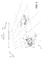
- Figure 2 shows one embodiment of an implementation of a system in accordance with the present invention.
- Figure 3 is a flow diagram of one embodiment of a method to determine a relative position between antennae in accordance with the present invention.
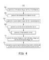
- Figure 4 is a flow diagram of one embodiment of a method to determine a relative position between a master antenna and either a first antenna or a second antenna in accordance with the present invention.
- FIG. 1 is a block diagram of one embodiment of a system 10 in accordance with the present invention.
- System 10 comprises at least three antennae, such as a master antenna 20, and at least two other antennae represented generally by the numeral 45.
- the other antennae 45 include a first antenna 30 and a second antenna 40.
- the system 10 also includes a master receiver 22, and other receivers represented generally by the numeral 35.
- the other receivers 35 comprise a first receiver 32 and a second receiver 43.
- the system 10 also includes a programmable processor 50, a memory 28, and instructions 120, e. g., software, firmware or other program code.
- the instructions 120 are stored in a storage medium 122.
- the master receiver 22, the other receivers 35, and the memory 28 are communicatively coupled to the programmable processor 50.
- the other receivers 35 are communicatively coupled to the programmable processor 50 via a wireless communication link (for example, a radio-frequency (RF) communication link).
- the other receivers 35 are communicatively coupled to the programmable processor 50 via a wired (for example, an optical fiber or copper wire communication link) and wireless communication link.
- the master receiver 22 is communicatively coupled to the programmable processor 50 via a wireless communication link. In yet another implementation of this embodiment, the master receiver 22 is communicatively coupled via a wired communication link. In yet another implementation of this embodiment, the master receiver 22 is communicatively coupled via a wired and a wireless communication link. In yet another implementation of this embodiment, at least one Kalman filter is included in the instructions 120 executed by the programmable processor 50.
- a plurality of navigational satellites 100, 102, and 104 emit global positioning system signals, the wavefronts of which are shown and represented generally by the numeral 200 (also referred to herein as "signals 200").
- the signals 200 are transmitted at a carrier frequency ⁇ c that is equal to the speed of light divided by the carrier wavelength ⁇ c .
- the master antenna 20, the first antenna 30, and the second antenna 40 each receive the global positioning system signals 200 from the plurality of navigational satellites 100, 102, and 104 within range of the antennae 20, 30, and 40.
- the master antenna 20 is also referred to herein as “user antenna 20" and the other antennae 45 are also referred to herein as “slave antennae 45,” or “reference antennae 45.”
- the plurality of navigational satellites 100, 102, and 104 are included in the system 10.
- the master receiver 22 is communicatively coupled to the master antenna 20.
- the master receiver 22 tracks and demodulates the signals 200 received at the master antenna 20 from the plurality of navigational satellites 100, 102, and 104.
- the master receiver 22 creates pseudo-range data and carrier phase measurement responsive to receiving the global positioning system signals 200.
- the pseudo-range data and carrier phase measurements generated at the master receiver 22 are sent to the programmable processor 50.
- the master antenna 20, the master receiver 22 and the programmable processor 50 are co-located.
- the master antenna 20, the master receiver 22 and the programmable processor 50 are co-located in an aircraft.
- At least two other receivers 35 are communicatively coupled to a respective one of the other antennae 45.
- Each of the other receivers 35 tracks and demodulates the signals 200 received from the plurality of navigational satellites 100, 102 and 104 at an associated other antennae 45.
- Each of the other receivers 35 creates pseudo-range data and carrier phase measurements for the associated other antennae 45.
- the pseudo-range data and carrier phase measurements generated at the other receivers 35 are sent to the programmable processor 50.
- the first receiver 32 is communicatively coupled to antenna 30.
- the first receiver 32 tracks and demodulates the signals 200 received at the first antenna 30 from the plurality of navigational satellites 100, 102 and 104.
- the first receiver 32 creates pseudo-range data and carrier phase measurements for the first antenna 30 and sends the generated pseudo-range data and carrier phase measurements to the programmable processor 50.
- the second receiver 42 is communicatively coupled to antenna 40.
- the second receiver 42 tracks and demodulates the signals 200 received at the second antenna 40 from the plurality of navigational satellites 100, 102 and 104.
- the second receiver 42 creates pseudo-range data and carrier phase measurements for the second antenna 40 and sends the generated pseudo-range data and carrier phase measurements to the programmable processor 50.
- Each of the other antennae 45 forms a baseline with the master antenna 20.
- the first antenna 30 forms a first baseline D 1 with the master antenna 20.
- the first baseline D 1 is directionally represented as a first baseline vector 151 from the master antenna 20 to the first antenna 30.
- the second antenna 40 forms a second baseline D 2 with the master antenna 20.
- the second baseline D 2 is directionally represented as second baseline vector 152 from the second antenna 40 to the master antenna 20.
- At least two of the other antennae 45 also form a fixed baseline D fix with each other.
- the fixed baseline D fix is directionally represented as fixed baseline vector 150 from the first antenna 30 to the second antenna 40.
- the first baseline vector 151, the second baseline vector 152, and the fixed baseline vector 150 form a closed triangle represented generally by the numeral 155.
- the programmable processor 50 receives the generated pseudo-range data and carrier phase measurements from the master receiver 22, the first receiver 32, and the second receiver 42.
- the programmable processor generates phase integer sets based on the phase carrier measurements and calculates a relative position between the master antenna 20 and at least one other antenna 45 based on the fixed baseline D fix between two of the other antennae 45.
- the processor 50 executes instructions 120 to analyze the raw pseudo-range data and the carrier phase data received from the receivers 22, 32, and 42.
- a phase integer set is generated for each of the first baseline D 1 and the second baseline D 2 .
- the receivers 22, 32, and 42 process the received signals 200 through eight channels and send the raw data from the eight channels to the programmable processor 50.
- the programmable processor 50 processes the raw data from the eight channels from the three receivers 22, 32, and 42 to generate one integer for each of the eight channels. These eight integers are processed to form a 1 X 8 vector array, which is the phase integer set.
- phase integer sets The software used to generate the phase integer sets and the methods to generate phase integer sets are known by one of ordinary skill in the art.
- the generation of phase integer sets is described in " The least-squares ambiguity decorrelation adjustment: a method for fast GPS integer ambiguity estimation” by P. J. G. Teunissen published in the Journal of Geodesy (1995) 70:65-82 referred to herein as the Teunissen paper.
- the programmable processor 50 calculates a relative position between the master antenna 20 and either the first antenna 30 or the second antenna 40 based on the phase integer sets and the fixed baseline 159 as described in detail below with reference to methods 300 and 400 as shown in Figures 3 and 4, respectively.
- FIG. 2 shows one embodiment of an implementation of a system 11 in accordance with the present invention.
- System 11 incorporates system 10 ( Figure 1), an aircraft 130, and an aircraft carrier 135.
- system 11 the master antenna 20 and master receiver 22 are positioned in an aircraft 130 and the other antennae 45 and the associated other receivers 35 are positioned on an aircraft carrier 135.
- the other antennae 45 are positioned on a moving vehicle.
- the plurality of navigational satellites 100, 102, and 104 are included in the system 11.
- two antennae are positioned a fixed distance from each other in or on the aircraft 130 and a second antenna is positioned on the aircraft carrier 135.
- the master antenna 20 and the first antenna 30 are positioned at ends of a fixed baseline on the aircraft 130 while the third antenna 40 is located on the aircraft carrier 135.
- the programmable processor 50 is located in the aircraft 130.
- Figure 3 is a flow diagram of one embodiment of a method 300 to determine a relative position between antennae in accordance with the present invention.
- the embodiment of method 300 is described as being implemented using system 10 of Figure 1.
- at least a portion of the processing of method 300 is performed by instructions 120 executing on the programmable processor 50, which is communicatively coupled to the master receiver 22, first receiver 32 and second receiver 42.
- a global positioning system signal is received at three antennae.
- the received signal is sent from each antenna to a communicatively coupled receiver.
- the communicatively coupled receiver processes the received signal.
- the global positioning system signals 200 emitted from a plurality of satellites 100, 102 and 104 are received at the master antenna 20, the first antenna 30 and the second antenna 40 ( Figure 1).
- the received signal 200 is sent from the master antenna 20, the first antenna 30 and the second antenna 40 to the respective master receiver 22, the first receiver 32 and the second receiver 42 for processing by the respective receiver.
- the master receiver generates pseudo-range data and carrier phase measurements responsive to receiving the global positioning system signal from the master antenna.
- the master receiver 22 generates pseudo-range data and carrier phase measurements responsive to the master antenna 20 receiving the global positioning system signal 200 and sending it to the master receiver 22.
- the pseudo-range data and carrier phase measurements are generated at receivers associated with each of the other antennae in response to the other antennae receiving the global positioning system signal and sending it to the associate receiver.
- the pseudo-range data and carrier phase measurements are generated at the other receivers 35 responsive to the other antennae 45 receiving the global positioning system signal 200 and sending it to an associated other receiver 35.
- the pseudo-range data and carrier phase measurements are received from the master receiver and from the other receivers responsive to the generating of the pseudo-range data and the carrier phase measurements.
- the programmable processor 50 receives the pseudo-range data and carrier phase measurements from the master receiver 22 and from the other receivers 35 when the pseudo-range data and the carrier phase measurements are generated at the master receiver 22, and the other receivers 35.
- the pseudo-range data and the carrier phase measurements generated at the antennae are processed.
- the programmable processor 500 executes instructions 120 stored in the storage medium 122 to process the pseudo-range data and the carrier phase measurements generated at master antenna 20 and other antennae 45.
- phase integer sets are generated as a result of the processing at block 310.
- the programmable processor 50 generates the phase integer sets.
- a relative position between the master antenna and at least one other antenna is calculated based on the generated phase integer sets and a fixed baseline between two of the other antennae.
- the programmable processor 50 calculates the relative position between the master antenna 20 and at least one of the other antennae 45. The calculation is based on the generated phase integer sets and a fixed baseline D fix between two of the other antennae 45.
- the method 400 of Figure 4 describes how the fixed baseline D fix is used with the phase integer sets to calculate the relative position between the master antenna 20 and at least one of the other antennae 45.
- method 300 precisely determines the relative position between the master antenna 20 and at least one of the other antennae 45, since phase carrier measurements have lower noise levels and smaller multi-path errors than code measurements.
- the programmable processor 50 in the aircraft 130 that is landing on the aircraft carrier 134 continuously determines the relative position of the aircraft carrier 135 to within a few centimeters.
- Figure 4 is a flow diagram of one embodiment of a method 400 to determine a relative position between a master antenna 20 and either a first antenna 30 or a second antenna 40 in accordance with the present invention.
- the embodiment of method 400 is described as being implemented using system 10 of Figure 1.
- at least a portion of the processing of method 400 is performed by instructions 120 executing on the programmable processor 50, which is communicatively coupled to the master receiver 22, first receiver 32 and second receiver 42.
- a first phase integer set for a first baseline formed between the master antenna and the first antenna is generated.
- the first phase integer set comprises an array of k values for the carrier frequency received from each of the satellites that are within range of the master antenna and the first antenna.
- the programmable processor 50 generates the first phase integer set for the first baseline D 1 formed between the master antenna 20 and the first antenna 30.
- An exemplary phase integer set for the first baseline D 1 for the carrier frequency received from the satellites 100, 102, 104 is the vector (k 1 100 , k 1 102 , k 1 104 ).
- k i n is the k value determined for a baseline at the carrier frequency ⁇ c of the signal 200 received from the n th satellite at the i th antenna.
- an estimated first baseline vector for the first baseline is generated based on the first phase integer set.
- the estimated first baseline vector is estimated based on the k-vector, such exemplary k-vector (k 1 100 , k 1 102 , k 1 104 ), as is known by one of ordinary skill in the art and as discussed in the Teunissen paper.
- the programmable processor 50 executes instructions 120 to estimated first baseline vector, which is associated with the first baseline vector 151, based on the first phase integer set.
- the estimated first baseline vector is an estimate of the length and direction of the first baseline vector 151.
- a second phase integer set for a second baseline formed between the master antenna and the second antenna is generated.
- the second phase integer set comprises an array of k values for the carrier frequency received from each of the satellites that are within range of the master antenna and the second antenna.
- the programmable processor 50 generates the second phase integer set for the second baseline D 2 formed between the master antenna 20 and the second antenna 40.
- An exemplary phase integer set for the second baseline D 2 for the carrier frequency received from the satellites 100, 102, 104 is the k-vector (k 2 100 , k 2 102 , k 2 104 ) formed from the k values.
- an estimated second baseline vector for the second baseline D 2 is generated based on the second phase integer set.
- the second baseline vector is estimated based on the k-vector, such exemplary k-vector (k 1 100 , k 1 102 , k 1 104 ).
- the programmable processor 50 executes instructions 120 to estimated second baseline vector, which is associated with the second baseline vector 152, based on the first phase integer set.
- the estimated second baseline vector is an estimate of the length and direction of the second baseline vector 152.
- a fixed baseline vector is generated by retrieving a length D fix of the fixed baseline between the first antenna 30 and the second antenna 40.
- the programmable processor 50 retrieves the length D fix of the fixed baseline between the first antenna 30 and the second antenna 40 from the memory 22 and uses information indicative of the global positioning of the first antenna 30 with respect to the global positioning of the second antenna 40 to generate a direction from the first antenna 30 to the second antenna 40.
- the programmable processor 50 then generates the fixed baseline vector 150.
- the phase integers of the first phase integer set and the second phase integer set are verified, based on a summation of the estimated first baseline vector, the estimated second baseline vector, and the fixed baseline vector 150.
- the first baseline vector 151, the second baseline vector 152, and the fixed baseline vector 150 form a closed triangle 155.
- the programmable processor 50 uses the fixed baseline 150 and the phase integers of the first phase integer set (k 2 100 , k 2 102 , k 2 104 ) and the second phase integer set (k 1 100 , k 1 102 , k 1 104 ) to trigonometrically verify which of the k values in the first and second phase integer sets sum to form the closed triangle.
- a relative position between the master antenna and at least one of the second antenna and the second antenna is calculated based on the verification of the phase integers.
- the programmable processor 50 executes instructions 120 to calculate the relative position between the master antenna 20 and the first antenna 30.
- the programmable processor 50 executes instructions 120 to calculate the relative position between the master antenna 20 and the second antenna 40.
- the programmable processor 50 executes instructions 120 to calculate the relative position between the master antenna 20 and both the first antenna 30 and the second antenna 40. Since method 400 relies on carrier frequency measurements and not on code measurement, method 400 is highly accurate. By continuously implementing method 400, the programmable processor 50 in the aircraft 130 that is landing on the aircraft carrier 134 continuously determines the relative position of the aircraft carrier 135 to within a few centimeters.
- the reliability of the methods 300 and 400 can be improved with multiple Global positioning system antennae having more than one fixed baseline.
- the instructions 120 is the software generated in the SBJPALS or JPALS programs as described in the 11/180,295 Application.
Landscapes
- Engineering & Computer Science (AREA)
- Radar, Positioning & Navigation (AREA)
- Remote Sensing (AREA)
- Physics & Mathematics (AREA)
- General Physics & Mathematics (AREA)
- Computer Networks & Wireless Communication (AREA)
- Position Fixing By Use Of Radio Waves (AREA)
Abstract
Description
- This application is related to
United States Patent Applications Serial No. 11/180,295 (Attorney Docket No. H0009900-5823) having a title of "METHODS AND SYSTEMS OF RELATIVE NAVIGATION FOR SHIPBOARD LANDINGS" (also referred to here as the "11/180,295 11/180,295 - Existing requirements for providing precision approach and landing navigation during flight for both commercial and military aircraft include accuracy, integrity, availability, and continuity of function. Traditionally, location determination incorporates the use of global positioning system (GPS)-based satellite navigation that can provide accuracy down to the centimeter level. The integrity of a navigation system is typically expressed in terms of confidence levels. The higher the confidence level, the more reliable the information provided. Availability and continuity provide assurances that the system will be available not only at the beginning of the operation, but throughout the entire duration of the flight.
- Meeting these requirements is especially crucial for autonomous shipboard landings on seaborne aircraft carriers. Proposals of using GPS to generate relative navigation and guidance to meet these challenges can provide the accuracy and integrity required, however, a shipboard approach and landing is more demanding than typical land-based approaches and landings. Aircraft navigation systems used in a shipboard approach and landing must continue to meet the requirements listed above even at sea under severe weather conditions and demanding electromagnetic environments. This is particularly important when landing on an aircraft carrier, where vertical landing errors of more than 0.3 meters is unacceptable and can result in unsafe landing conditions.
- Some of the factors to consider during autonomous shipboard landings are a lack of visibility, operating under combat conditions, and a dynamically changing touchdown point. In addition to low rate GPS measurement data other, higher rate, measurements are needed in order to evaluate the relative state between aircraft and aircraft carrier, i.e., the aircraft's position and velocity with respect to the moving runway and touchdown point, as accurately as possible during a precision approach and landing. Existing navigational aids include using an inertial navigation system (INS) to measure the position and altitude of the approaching aircraft in conjunction with GPS. With a combination GPS/INS solution, the short-term measurement data from the INS, which is susceptible to drift errors over time, is corrected by the exact location and time references provided by satellite navigation.
- Rapid and high-precision positioning with a Global Navigation Satellite System (GNSS) is feasible only when very precise carrier-phase observations can be used. Raw carrier phase measurements are generally the by-product of all GPS receivers. These phase measurements cannot be used as "range" observations because they are ambiguous.
- Carrier phase measurements are ambiguous by an unknown, integer number of cycles. These integer ambiguity parameters need to be resolved before carrier-phase observations can begin to serve as very precise range measurements. For precise navigation, reliable real-time ambiguity resolution is necessary. For short-distance baseline, with current GPS, the reliability of ambiguity resolution with single-epoch data is not high. This makes it impossible to realize real-time precise navigation for safety-related applications. For medium- and long-distance baselines, with current GPS, it generally takes more than twenty minutes to get reliable ambiguity resolution. This low efficiency makes it impossible for global positioning system to be used in many applications where both high precision and high efficiency are needed.
- A first aspect of the present invention includes a method to determine a relative position between antennae comprising generating phase carrier measurements for a carrier frequency and at least three antennae including a master antenna and other antennae, generating phase integer sets based on the phase carrier measurements, and calculating a relative position between the master antenna and at least one other antenna based on the generated phase integer sets and a fixed baseline between two of the other antennae.
- Figure 1 is a block diagram of one embodiment of a system in accordance with the present invention.
- Figure 2 shows one embodiment of an implementation of a system in accordance with the present invention.
- Figure 3 is a flow diagram of one embodiment of a method to determine a relative position between antennae in accordance with the present invention.
- Figure 4 is a flow diagram of one embodiment of a method to determine a relative position between a master antenna and either a first antenna or a second antenna in accordance with the present invention.
- In accordance with common practice, the various described features are not drawn to scale but are drawn to emphasize features relevant to the present invention. Reference characters denote like elements throughout figures and text.
- In the following detailed description, reference is made to the accompanying drawings that form a part hereof, and in which is shown by way of illustration specific illustrative embodiments in which the invention may be practiced. These embodiments are described in sufficient detail to enable those skilled in the art to practice the invention, and it is to be understood that other embodiments may be utilized and that logical, mechanical and electrical changes may be made without departing from the scope of the present invention. The following detailed description is, therefore, not to be taken in a limiting sense.
- Figure 1 is a block diagram of one embodiment of a
system 10 in accordance with the present invention.System 10 comprises at least three antennae, such as amaster antenna 20, and at least two other antennae represented generally by thenumeral 45. As shown in Figure 1, theother antennae 45 include a first antenna 30 and asecond antenna 40. Thesystem 10 also includes amaster receiver 22, and other receivers represented generally by thenumeral 35. As shown in Figure 1, theother receivers 35 comprise afirst receiver 32 and a second receiver 43. Thesystem 10 also includes aprogrammable processor 50, a memory 28, andinstructions 120, e. g., software, firmware or other program code. Theinstructions 120 are stored in astorage medium 122. Themaster receiver 22, theother receivers 35, and the memory 28 are communicatively coupled to theprogrammable processor 50. In one implementation of this embodiment, theother receivers 35 are communicatively coupled to theprogrammable processor 50 via a wireless communication link (for example, a radio-frequency (RF) communication link). In another implementation of this embodiment, theother receivers 35 are communicatively coupled to theprogrammable processor 50 via a wired (for example, an optical fiber or copper wire communication link) and wireless communication link. - In yet another implementation of this embodiment, the
master receiver 22 is communicatively coupled to theprogrammable processor 50 via a wireless communication link. In yet another implementation of this embodiment, themaster receiver 22 is communicatively coupled via a wired communication link. In yet another implementation of this embodiment, themaster receiver 22 is communicatively coupled via a wired and a wireless communication link. In yet another implementation of this embodiment, at least one Kalman filter is included in theinstructions 120 executed by theprogrammable processor 50. - A plurality of
navigational satellites signals 200"). Thesignals 200 are transmitted at a carrier frequency νc that is equal to the speed of light divided by the carrier wavelength λc. Themaster antenna 20, the first antenna 30, and thesecond antenna 40 each receive the globalpositioning system signals 200 from the plurality ofnavigational satellites antennae master antenna 20 is also referred to herein as "user antenna 20" and theother antennae 45 are also referred to herein as "slave antennae 45," or "reference antennae 45." In one implementation of this embodiment, the plurality ofnavigational satellites system 10. - The
master receiver 22 is communicatively coupled to themaster antenna 20. Themaster receiver 22 tracks and demodulates thesignals 200 received at themaster antenna 20 from the plurality ofnavigational satellites master receiver 22 creates pseudo-range data and carrier phase measurement responsive to receiving the globalpositioning system signals 200. The pseudo-range data and carrier phase measurements generated at themaster receiver 22 are sent to theprogrammable processor 50. In one implementation of this embodiment, themaster antenna 20, themaster receiver 22 and theprogrammable processor 50 are co-located. In another implementation of this embodiment, themaster antenna 20, themaster receiver 22 and theprogrammable processor 50 are co-located in an aircraft. - At least two
other receivers 35, also referred to herein as "first receiver 32 andsecond receiver 42," are communicatively coupled to a respective one of theother antennae 45. Each of theother receivers 35 tracks and demodulates thesignals 200 received from the plurality ofnavigational satellites other antennae 45. Each of theother receivers 35 creates pseudo-range data and carrier phase measurements for the associatedother antennae 45. The pseudo-range data and carrier phase measurements generated at theother receivers 35 are sent to theprogrammable processor 50. - For the exemplary implementation shown in Figure 1, the
first receiver 32 is communicatively coupled to antenna 30. Thefirst receiver 32 tracks and demodulates thesignals 200 received at the first antenna 30 from the plurality ofnavigational satellites first receiver 32 creates pseudo-range data and carrier phase measurements for the first antenna 30 and sends the generated pseudo-range data and carrier phase measurements to theprogrammable processor 50. Likewise, thesecond receiver 42 is communicatively coupled toantenna 40. Thesecond receiver 42 tracks and demodulates thesignals 200 received at thesecond antenna 40 from the plurality ofnavigational satellites second receiver 42 creates pseudo-range data and carrier phase measurements for thesecond antenna 40 and sends the generated pseudo-range data and carrier phase measurements to theprogrammable processor 50. - Each of the
other antennae 45 forms a baseline with themaster antenna 20. The first antenna 30 forms a first baseline D1 with themaster antenna 20. The first baseline D1 is directionally represented as afirst baseline vector 151 from themaster antenna 20 to the first antenna 30. Thesecond antenna 40 forms a second baseline D2 with themaster antenna 20. The second baseline D2 is directionally represented as second baseline vector 152 from thesecond antenna 40 to themaster antenna 20. At least two of theother antennae 45 also form a fixed baseline Dfix with each other. The fixed baseline Dfix is directionally represented as fixedbaseline vector 150 from the first antenna 30 to thesecond antenna 40. Thefirst baseline vector 151, the second baseline vector 152, and the fixedbaseline vector 150 form a closed triangle represented generally by the numeral 155. - The
programmable processor 50 receives the generated pseudo-range data and carrier phase measurements from themaster receiver 22, thefirst receiver 32, and thesecond receiver 42. The programmable processor generates phase integer sets based on the phase carrier measurements and calculates a relative position between themaster antenna 20 and at least oneother antenna 45 based on the fixed baseline Dfix between two of theother antennae 45. Theprocessor 50 executesinstructions 120 to analyze the raw pseudo-range data and the carrier phase data received from thereceivers - In an exemplary case, if there are eight navigational satellites sending the
signals 200 at the carrier frequency νc, then thereceivers programmable processor 50. Theprogrammable processor 50 processes the raw data from the eight channels from the threereceivers - The software used to generate the phase integer sets and the methods to generate phase integer sets are known by one of ordinary skill in the art. The generation of phase integer sets is described in "The least-squares ambiguity decorrelation adjustment: a method for fast GPS integer ambiguity estimation" by P. J. G. Teunissen published in the Journal of Geodesy (1995) 70:65-82 referred to herein as the Teunissen paper.
- The
programmable processor 50 calculates a relative position between themaster antenna 20 and either the first antenna 30 or thesecond antenna 40 based on the phase integer sets and the fixed baseline 159 as described in detail below with reference tomethods - Figure 2 shows one embodiment of an implementation of a
system 11 in accordance with the present invention.System 11 incorporates system 10 (Figure 1), anaircraft 130, and anaircraft carrier 135. Insystem 11, themaster antenna 20 andmaster receiver 22 are positioned in anaircraft 130 and theother antennae 45 and the associatedother receivers 35 are positioned on anaircraft carrier 135. In another embodiment, theother antennae 45 are positioned on a moving vehicle. In another implementation of this embodiment, the plurality ofnavigational satellites system 11. - In yet another implementation of this embodiment, two antennae are positioned a fixed distance from each other in or on the
aircraft 130 and a second antenna is positioned on theaircraft carrier 135. For example, themaster antenna 20 and the first antenna 30 are positioned at ends of a fixed baseline on theaircraft 130 while thethird antenna 40 is located on theaircraft carrier 135. In this case, theprogrammable processor 50 is located in theaircraft 130. - Figure 3 is a flow diagram of one embodiment of a
method 300 to determine a relative position between antennae in accordance with the present invention. The embodiment ofmethod 300 is described as being implemented usingsystem 10 of Figure 1. In such an embodiment, at least a portion of the processing ofmethod 300 is performed byinstructions 120 executing on theprogrammable processor 50, which is communicatively coupled to themaster receiver 22,first receiver 32 andsecond receiver 42. - At
block 302, a global positioning system signal is received at three antennae. The received signal is sent from each antenna to a communicatively coupled receiver. The communicatively coupled receiver processes the received signal. In one implementation of this embodiment, the global positioning system signals 200 emitted from a plurality ofsatellites master antenna 20, the first antenna 30 and the second antenna 40 (Figure 1). The receivedsignal 200 is sent from themaster antenna 20, the first antenna 30 and thesecond antenna 40 to therespective master receiver 22, thefirst receiver 32 and thesecond receiver 42 for processing by the respective receiver. - At
block 304, the master receiver generates pseudo-range data and carrier phase measurements responsive to receiving the global positioning system signal from the master antenna. In one implementation of this embodiment, themaster receiver 22 generates pseudo-range data and carrier phase measurements responsive to themaster antenna 20 receiving the globalpositioning system signal 200 and sending it to themaster receiver 22. - At
block 306, the pseudo-range data and carrier phase measurements are generated at receivers associated with each of the other antennae in response to the other antennae receiving the global positioning system signal and sending it to the associate receiver. In one implementation of this embodiment, the pseudo-range data and carrier phase measurements are generated at theother receivers 35 responsive to theother antennae 45 receiving the globalpositioning system signal 200 and sending it to an associatedother receiver 35. - At
block 308, the pseudo-range data and carrier phase measurements are received from the master receiver and from the other receivers responsive to the generating of the pseudo-range data and the carrier phase measurements. In one implementation of this embodiment, theprogrammable processor 50 receives the pseudo-range data and carrier phase measurements from themaster receiver 22 and from theother receivers 35 when the pseudo-range data and the carrier phase measurements are generated at themaster receiver 22, and theother receivers 35. - At
block 310, the pseudo-range data and the carrier phase measurements generated at the antennae are processed. In one implementation of this embodiment, the programmable processor 500 executesinstructions 120 stored in thestorage medium 122 to process the pseudo-range data and the carrier phase measurements generated atmaster antenna 20 andother antennae 45. - At
block 312, phase integer sets are generated as a result of the processing atblock 310. In one implementation of this embodiment, theprogrammable processor 50 generates the phase integer sets. - At
block 314, a relative position between the master antenna and at least one other antenna is calculated based on the generated phase integer sets and a fixed baseline between two of the other antennae. In one implementation of this embodiment, theprogrammable processor 50 calculates the relative position between themaster antenna 20 and at least one of theother antennae 45. The calculation is based on the generated phase integer sets and a fixed baseline Dfix between two of theother antennae 45. Themethod 400 of Figure 4 describes how the fixed baseline Dfix is used with the phase integer sets to calculate the relative position between themaster antenna 20 and at least one of theother antennae 45. - Since
method 300 relies on carrier frequency measurements and not on code measurement,method 300 precisely determines the relative position between themaster antenna 20 and at least one of theother antennae 45, since phase carrier measurements have lower noise levels and smaller multi-path errors than code measurements. By continuously implementingmethod 300, theprogrammable processor 50 in theaircraft 130 that is landing on the aircraft carrier 134 continuously determines the relative position of theaircraft carrier 135 to within a few centimeters. - Figure 4 is a flow diagram of one embodiment of a
method 400 to determine a relative position between amaster antenna 20 and either a first antenna 30 or asecond antenna 40 in accordance with the present invention. The embodiment ofmethod 400 is described as being implemented usingsystem 10 of Figure 1. In such an embodiment, at least a portion of the processing ofmethod 400 is performed byinstructions 120 executing on theprogrammable processor 50, which is communicatively coupled to themaster receiver 22,first receiver 32 andsecond receiver 42. - At
block 402, a first phase integer set for a first baseline formed between the master antenna and the first antenna is generated. The first phase integer set comprises an array of k values for the carrier frequency received from each of the satellites that are within range of the master antenna and the first antenna. In one implementation of this embodiment, theprogrammable processor 50 generates the first phase integer set for the first baseline D1 formed between themaster antenna 20 and the first antenna 30. An exemplary phase integer set for the first baseline D1 for the carrier frequency received from thesatellites signal 200 received from the nth satellite at the ith antenna. - At
block 404, an estimated first baseline vector for the first baseline is generated based on the first phase integer set. The estimated first baseline vector is estimated based on the k-vector, such exemplary k-vector (k1 100, k1 102, k1 104), as is known by one of ordinary skill in the art and as discussed in the Teunissen paper. In one implementation of this embodiment, theprogrammable processor 50 executesinstructions 120 to estimated first baseline vector, which is associated with thefirst baseline vector 151, based on the first phase integer set. In this case, the estimated first baseline vector is an estimate of the length and direction of thefirst baseline vector 151. - At
block 406, a second phase integer set for a second baseline formed between the master antenna and the second antenna is generated. The second phase integer set comprises an array of k values for the carrier frequency received from each of the satellites that are within range of the master antenna and the second antenna. In one implementation of this embodiment, theprogrammable processor 50 generates the second phase integer set for the second baseline D2 formed between themaster antenna 20 and thesecond antenna 40. An exemplary phase integer set for the second baseline D2 for the carrier frequency received from thesatellites - At
block 408, an estimated second baseline vector for the second baseline D2 is generated based on the second phase integer set. The second baseline vector is estimated based on the k-vector, such exemplary k-vector (k1 100, k1 102, k1 104). In one implementation of this embodiment, theprogrammable processor 50 executesinstructions 120 to estimated second baseline vector, which is associated with the second baseline vector 152, based on the first phase integer set. In this case, the estimated second baseline vector is an estimate of the length and direction of the second baseline vector 152. - At
block 410, a fixed baseline vector is generated by retrieving a length Dfix of the fixed baseline between the first antenna 30 and thesecond antenna 40. In one implementation of this embodiment, theprogrammable processor 50 retrieves the length Dfix of the fixed baseline between the first antenna 30 and thesecond antenna 40 from thememory 22 and uses information indicative of the global positioning of the first antenna 30 with respect to the global positioning of thesecond antenna 40 to generate a direction from the first antenna 30 to thesecond antenna 40. Theprogrammable processor 50 then generates the fixedbaseline vector 150. - At
block 412, the phase integers of the first phase integer set and the second phase integer set are verified, based on a summation of the estimated first baseline vector, the estimated second baseline vector, and the fixedbaseline vector 150. Referring now to the exemplary configuration of antennae in Figure 1, thefirst baseline vector 151, the second baseline vector 152, and the fixedbaseline vector 150 form aclosed triangle 155. In this implementation, theprogrammable processor 50 uses the fixedbaseline 150 and the phase integers of the first phase integer set (k2 100, k2 102, k2 104) and the second phase integer set (k1 100, k1 102, k1 104) to trigonometrically verify which of the k values in the first and second phase integer sets sum to form the closed triangle. With D1 vectorially representing thefirst baseline vector 151 from themaster antenna 20 to the first antenna 30, Dfix vectorially representing the fixedbaseline vector 150 from the first antenna 30 to thesecond antenna 40, and D2 vectorially representing the second baseline vector 152 from thesecond antenna 40 to themaster antenna 20, the sum to form the closed triangle is written as the equation is D1+Dfix+D2=0. - At
block 414, a relative position between the master antenna and at least one of the second antenna and the second antenna is calculated based on the verification of the phase integers. In one implementation of this embodiment, theprogrammable processor 50 executesinstructions 120 to calculate the relative position between themaster antenna 20 and the first antenna 30. In another implementation of this embodiment, theprogrammable processor 50 executesinstructions 120 to calculate the relative position between themaster antenna 20 and thesecond antenna 40. In yet another implementation of this embodiment, theprogrammable processor 50 executesinstructions 120 to calculate the relative position between themaster antenna 20 and both the first antenna 30 and thesecond antenna 40. Sincemethod 400 relies on carrier frequency measurements and not on code measurement,method 400 is highly accurate. By continuously implementingmethod 400, theprogrammable processor 50 in theaircraft 130 that is landing on the aircraft carrier 134 continuously determines the relative position of theaircraft carrier 135 to within a few centimeters. - The reliability of the
methods instructions 120 is the software generated in the SBJPALS or JPALS programs as described in the 11/180,295 Application. - Although specific embodiments have been illustrated and described herein, it will be appreciated by those of ordinary skill in the art that any arrangement, which is calculated to achieve the same purpose, may be substituted for the specific embodiment shown. This application is intended to cover any adaptations or variations of the present invention. Therefore, it is manifestly intended that this invention be limited only by the claims and the equivalents thereof.
Claims (10)
- A method to determine a relative position between antennae, the method comprising:generating phase carrier measurements for a carrier frequency and at least three antennae including a master antenna (20) and other antennae (45);generating phase integer sets based on the phase carrier measurements; andcalculating a relative position between the master antenna and at least one other antenna (30) based on the generated phase integer sets and a fixed baseline between two of the other antennae.
- The method of claim 1, wherein generating phase carrier measurements comprises:receiving a global positioning system signal at the at least three antennae (20);generating pseudo-range data and carrier phase measurements at the master receiver (22) responsive to receiving the global positioning system signal at the master antenna (20); andgenerating pseudo-range data and carrier phase measurements at receivers (35) associated with each of the other antennae (45) responsive to the respective receiving the global positioning system signal at each of the other antennae.
- The method of claim 2, further comprising:receiving pseudo-range data and carrier phase measurements from the master receiver (22) and from the other receivers (35) responsive to the generating of the pseudo-range data and the carrier phase measurements, wherein generating phase integer sets based on the phase carrier measurements comprises:processing the pseudo-range data and the carrier phase measurements generated at the at least three antennae to generate the phase integer sets.
- The method of claims 1 , wherein generating phase carrier measurements for a carrier frequency and at least three antennae comprises:generating phase carrier measurements for the carrier frequency and the master antenna (20), a first antenna (30) and a second antenna (40).
- The method of claim 4, wherein generating phase integer sets based on the phase carrier measurements comprises:generating a first phase integer set for a first baseline (D1) formed between the master antenna (20) and the first antenna (30); andgenerating a second phase integer set for a second baseline (D2) formed between the master antenna (20) and the second antenna (40).
- The method of claim 5, wherein calculating the relative position between the master antenna (20) and at least one other antenna (30) comprises:generating an estimated first baseline vector (151) for the first baseline (D1), based on the first phase integer set;generating an estimated second baseline vector (152) for the second baseline (D2), based on the second phase integer set;generating a fixed baseline vector (150) by retrieving a length of the fixed baseline (Dfix) between the first antenna (30) and the second antenna (40);verifying the phase integers of the first phase integer set and the second phase integer set, based on a summation of the estimated first baseline vector, the estimated second baseline vector, and the fixed baseline vector; andcalculating the relative position between the master antenna and at least one of the first antenna and the second antenna based on the verification of the phase integers.
- A system (10) comprising:a master antenna (20) adapted to receive global positioning system signals from a plurality of navigational satellites (100);a master receiver (22) communicatively coupled to the master antenna, the master receiver adapted to track and demodulate the signals received at the master antenna, the master receiver further adapted to create pseudo-range data and carrier phase measurements;at least two other antennae (45) adapted to receive the global positioning system signals from the plurality of navigational satellites, each of the other antennae forming a baseline (D1) with the master antenna, and at least two of the other antennae form a fixed baseline (Dfix) with each other;at least two other receivers (35) communicatively coupled to a respective one of the other antennae, wherein each of the other receivers is adapted to track and demodulate the signals received at the respective antenna, each of the other receivers further adapted to create pseudo-range data and carrier phase measurements for the respective antenna; anda programmable processor (50) communicatively coupled to the master receiver and the other receivers, the programmable processor adapted to receive the generated pseudo-range data and carrier phase measurements from the master receiver and the other receivers, the programmable processor further adapted to generate phase integer sets based on the phase carrier measurements and adapted to calculate a relative position between the master antenna and at least one other antenna based on the fixed baseline between two of the other antennae.
- The system (10) of claim 7, further comprising:the plurality of navigational satellites (100) communicatively coupled to the master antenna (20) and the other antennae (45), the navigational satellites adapted to emit signals at the carrier frequency.
- The system (11) of claims 7 or 8, wherein the master antenna (20) is positioned in an aircraft (130), wherein the other antennae (45) comprise a first antenna (30) and a second antenna (40) positioned on an aircraft carrier (135), and wherein the programmable processor (50) is further adapted to generate a first phase integer set for a first baseline (D1) formed between the master antenna and the first antenna, to generate a second phase integer set for the second baseline (D2) formed between the master antenna and the second antenna, and to verify phase integer sets.
- A program product comprising program instructions (120), embodied on a storage medium (122), that are operable to cause a programmable processor (50) to:generate phase carrier measurements for a carrier frequency and at least three antennae including a master antenna (20) and other antennae (45);generate phase integer sets based on the phase carrier measurements; andcalculate a relative position between the master antenna and at least one other antenna (30) based on the generated phase integer sets and a fixed baseline (Dfix) between two of the other antennae.
Applications Claiming Priority (1)
| Application Number | Priority Date | Filing Date | Title |
|---|---|---|---|
| US11/537,247 US7411545B2 (en) | 2006-09-29 | 2006-09-29 | Carrier phase interger ambiguity resolution with multiple reference receivers |
Publications (1)
| Publication Number | Publication Date |
|---|---|
| EP1906201A1 true EP1906201A1 (en) | 2008-04-02 |
Family
ID=38962881
Family Applications (1)
| Application Number | Title | Priority Date | Filing Date |
|---|---|---|---|
| EP07117206A Withdrawn EP1906201A1 (en) | 2006-09-29 | 2007-09-25 | Carrier phase interger ambiguity resolution with multiple reference receivers |
Country Status (2)
| Country | Link |
|---|---|
| US (1) | US7411545B2 (en) |
| EP (1) | EP1906201A1 (en) |
Cited By (1)
| Publication number | Priority date | Publication date | Assignee | Title |
|---|---|---|---|---|
| CN105372691A (en) * | 2015-08-18 | 2016-03-02 | 中国人民解放军国防科学技术大学 | Long baseline satellite formation GNSS relative positioning method based on ambiguity fixing |
Families Citing this family (12)
| Publication number | Priority date | Publication date | Assignee | Title |
|---|---|---|---|---|
| US8949011B2 (en) * | 2005-09-14 | 2015-02-03 | Novatel Inc. | Helicopter ship board landing system |
| FR2917852B1 (en) * | 2007-06-25 | 2014-06-20 | Airbus France | METHOD AND DEVICE FOR DETERMINING A RELIABLE POSITION OF AN AIRCRAFT |
| WO2010091496A1 (en) | 2009-01-05 | 2010-08-19 | Smart Technologies Ulc | Gesture recognition method and interactive input system employing same |
| US20110231038A1 (en) * | 2010-03-17 | 2011-09-22 | Cmc Electronics Inc. | Aircraft landing system using relative gnss |
| US9829582B2 (en) * | 2011-09-19 | 2017-11-28 | Raytheon Company | Method and apparatus for differential global positioning system (DGPS)-based real time attitude determination (RTAD) |
| EP2855331B1 (en) | 2012-06-01 | 2018-12-26 | Seatrax, Inc. | System and method to determine relative velocity of crane and target load |
| US10114126B2 (en) | 2015-04-30 | 2018-10-30 | Raytheon Company | Sensor installation monitoring |
| US10551196B2 (en) | 2015-04-30 | 2020-02-04 | Raytheon Company | Sensor installation monitoring |
| WO2017066915A1 (en) * | 2015-10-20 | 2017-04-27 | 深圳市大疆创新科技有限公司 | Method and device for posture measurement in satellite navigation and unmanned aerial vehicle |
| US10247829B2 (en) | 2016-08-10 | 2019-04-02 | Raytheon Company | Systems and methods for real time carrier phase monitoring |
| US10969228B2 (en) * | 2018-06-05 | 2021-04-06 | Novatel Inc. | Relative position navigation system for multiple moving vehicles |
| CN111381256B (en) * | 2020-03-10 | 2022-07-26 | 上海卫星工程研究所 | Method and system for calculating phase center offset error of active remote sensing satellite antenna |
Citations (1)
| Publication number | Priority date | Publication date | Assignee | Title |
|---|---|---|---|---|
| US5991691A (en) * | 1997-02-20 | 1999-11-23 | Raytheon Aircraft Corporation | System and method for determining high accuracy relative position solutions between two moving platforms |
Family Cites Families (19)
| Publication number | Priority date | Publication date | Assignee | Title |
|---|---|---|---|---|
| US4232313A (en) * | 1972-09-22 | 1980-11-04 | The United States Of America As Represented By The Secretary Of The Navy | Tactical nagivation and communication system |
| US4032759A (en) * | 1975-10-24 | 1977-06-28 | The Singer Company | Shipboard reference for an aircraft navigation system |
| FR2689668B1 (en) * | 1992-04-07 | 1994-05-20 | Dassault Electronique | FIELD ANTI-COLLISION PROCESS AND DEVICE FOR AIRCRAFT. |
| US5548293A (en) * | 1993-03-24 | 1996-08-20 | Leland Stanford Junior University | System and method for generating attitude determinations using GPS |
| US5438337A (en) * | 1993-09-24 | 1995-08-01 | Northrop Grumman Corporation | Navigation system using re-transmitted GPS |
| US5432520A (en) * | 1993-10-18 | 1995-07-11 | Hughes Aircraft Company | SAR/GPS inertial method of range measurement |
| US5570097A (en) * | 1995-08-11 | 1996-10-29 | Northrop Grumman Corporation | Retransmitted GPS interferometric system |
| US5757317A (en) * | 1997-03-17 | 1998-05-26 | Litton Systems, Inc. | Relative navigation utilizing inertial measurement units and a plurality of satellite transmitters |
| US6005514A (en) * | 1997-09-15 | 1999-12-21 | United States Of America As Represented By The Administrator Of The National Aeronautics And Space Administration | Method for attitude determination using GPS carrier phase measurements from nonaligned antennas |
| US6246960B1 (en) * | 1998-11-06 | 2001-06-12 | Ching-Fang Lin | Enhanced integrated positioning method and system thereof for vehicle |
| US6727851B2 (en) * | 2000-09-20 | 2004-04-27 | The Corporation Of Mercer University | System for signal emitter location using rotational doppler measurement |
| US6667713B2 (en) * | 2001-08-24 | 2003-12-23 | Spectrum Astro | Self-monitoring satellite system |
| JP2003232845A (en) * | 2002-02-12 | 2003-08-22 | Furuno Electric Co Ltd | Direction and attitude detection device for moving objects |
| US6836707B2 (en) * | 2002-05-30 | 2004-12-28 | Honeywell International Inc. | Methods and systems for determining heave and heave rate of vessels |
| US6831599B2 (en) * | 2002-08-26 | 2004-12-14 | Honeywell International Inc. | Remote velocity sensor slaved to an integrated GPS/INS |
| US7024309B2 (en) * | 2003-08-28 | 2006-04-04 | The United States Of America As Represented By The Secretary Of The Air Force | Autonomous station keeping system for formation flight |
| US20050114023A1 (en) * | 2003-11-26 | 2005-05-26 | Williamson Walton R. | Fault-tolerant system, apparatus and method |
| US20060074558A1 (en) * | 2003-11-26 | 2006-04-06 | Williamson Walton R | Fault-tolerant system, apparatus and method |
| US7121183B2 (en) * | 2004-03-29 | 2006-10-17 | Honeywell International Inc. | Methods and systems for estimating weapon effectiveness |
-
2006
- 2006-09-29 US US11/537,247 patent/US7411545B2/en not_active Expired - Fee Related
-
2007
- 2007-09-25 EP EP07117206A patent/EP1906201A1/en not_active Withdrawn
Patent Citations (1)
| Publication number | Priority date | Publication date | Assignee | Title |
|---|---|---|---|---|
| US5991691A (en) * | 1997-02-20 | 1999-11-23 | Raytheon Aircraft Corporation | System and method for determining high accuracy relative position solutions between two moving platforms |
Non-Patent Citations (4)
| Title |
|---|
| GÉRARD LACHAPELLE ET AL: "Precise Aircraft-to-Aircraft Positioning Using a Multiple Receiver Configuration", PROCEEDINGS OF THE 1994 NATIONAL TECHNICAL MEETING OF THE INSTITUTE OF NAVIGATION, 24 January 1994 (1994-01-24), San Diego, CA , USA, pages 793 - 799, XP002466607 * |
| JAMES A. DOUTT ET AL.: "Determination of Distance Between a Moving Ship and Drifting Buoys to Centimeter-Level Accuracy at Sea Using L1 Phase GPS Receivers and Differential Moving-Base Kinematic Processing", PROCEEDINGS OF THE 11TH INTERNATIONAL TECHNICAL MEETING OF THE SATELLITE DIVISION OF THE INSTITUTE OF NAVIGATION, 15 September 1998 (1998-09-15), Nashville, TN, USA, pages 1301 - 1306, XP002466608 * |
| MOON-BEOM HEO ET AL: "Robust airborne navigation algorithms for SRGPS", POSITION LOCATION AND NAVIGATION SYMPOSIUM, 2004. PLANS 2004 MONTEREY, CA, USA 26-29 APRIL 2004, PISCATAWAY, NJ, USA,IEEE, US, 26 April 2004 (2004-04-26), pages 175 - 183, XP010768747, ISBN: 0-7803-8416-4 * |
| S. WEISENBURGER AND M. E. CANNON: "Performance Improvements Using Constraints in Marine OTF Ambiguity Resolution", PROCEEDINGS OF THE 1997 NATIONAL TECHNICAL MEETING OF THE INSTITUTE OF NAVIGATION, 14 January 1997 (1997-01-14), Santa Monica, CA , USA, pages 585 - 594, XP002466609 * |
Cited By (1)
| Publication number | Priority date | Publication date | Assignee | Title |
|---|---|---|---|---|
| CN105372691A (en) * | 2015-08-18 | 2016-03-02 | 中国人民解放军国防科学技术大学 | Long baseline satellite formation GNSS relative positioning method based on ambiguity fixing |
Also Published As
| Publication number | Publication date |
|---|---|
| US20080088504A1 (en) | 2008-04-17 |
| US7411545B2 (en) | 2008-08-12 |
Similar Documents
| Publication | Publication Date | Title |
|---|---|---|
| EP3123197B1 (en) | Methods and apparatus for determining angle of arrival (aoa) in a radar warning receiver | |
| EP1860456B1 (en) | Methods and systems for radar aided aircraft positioning for approaches and landings | |
| RU2621827C2 (en) | Board system for assisting piloting aircraft, based on system of gnss, having excess and dissimilar architecture for advanced reliability | |
| RU2363013C2 (en) | Method of combined use of kinematic mode in real time systems and regional, wide area or carrier phase global positioning system | |
| US8909471B1 (en) | Voting system and method using doppler aided navigation | |
| JP5329409B2 (en) | A method for fusing multiple GPS measurement types into a weighted least squares solution | |
| AU2003290935B2 (en) | All-weather precision guidance and navigation system | |
| KR101827820B1 (en) | Aircraft Landing Apparatus Using GNSS and SBAS Singals, and Control Method Thereof | |
| US10677916B2 (en) | Method and device for determining the position of an aircraft in an approach for a landing | |
| JP6593879B2 (en) | Satellite positioning system, positioning terminal, positioning method, and program | |
| US12442937B2 (en) | Techniques for determining geolocations | |
| US7411545B2 (en) | Carrier phase interger ambiguity resolution with multiple reference receivers | |
| US10809390B2 (en) | Positioning apparatus | |
| CN103090859B (en) | The method and apparatus that auxiliary guarantees the degree of accuracy of Aircraft position information on ground | |
| KR20150051747A (en) | Method for determining location of vehicle | |
| CN112703425A (en) | System and method for detecting pseudo-global navigation satellite system satellite signals | |
| KR20200106393A (en) | Method and Apparatus for UAV positioning by multipath error mitigation of GNSS data | |
| US20090135059A1 (en) | Method and apparatus for passive single platform geo-location | |
| RU2558699C1 (en) | Complex method of aircraft navigation | |
| Dai et al. | Heading-determination using the sensor-fusion based maritime PNT Unit | |
| RU2389042C2 (en) | Method of determining protective limit around position of moving body calculated from satellite signals | |
| RU2606241C1 (en) | Method of aircraft relative position determining during inter-plane navigation | |
| US10459088B2 (en) | Positioning method and terminal | |
| WO2020122852A1 (en) | Method for carrying out trajectory measurements (variants) and multi-positional phase system of trajectory measurements for realizing said method (variants) | |
| Palukhin et al. | EFFICIENCY INCREASING IN SATELLITE NAVIGATION SYSTEM OPERATIONAL PERFORMANCE OF DOMESTIC AND FOREIGN AIRCRAFTS |
Legal Events
| Date | Code | Title | Description |
|---|---|---|---|
| PUAI | Public reference made under article 153(3) epc to a published international application that has entered the european phase |
Free format text: ORIGINAL CODE: 0009012 |
|
| 17P | Request for examination filed |
Effective date: 20070925 |
|
| AK | Designated contracting states |
Kind code of ref document: A1 Designated state(s): AT BE BG CH CY CZ DE DK EE ES FI FR GB GR HU IE IS IT LI LT LU LV MC MT NL PL PT RO SE SI SK TR |
|
| AX | Request for extension of the european patent |
Extension state: AL BA HR MK YU |
|
| 17Q | First examination report despatched |
Effective date: 20080514 |
|
| AKX | Designation fees paid |
Designated state(s): DE FR |
|
| STAA | Information on the status of an ep patent application or granted ep patent |
Free format text: STATUS: THE APPLICATION IS DEEMED TO BE WITHDRAWN |
|
| 18D | Application deemed to be withdrawn |
Effective date: 20110401 |