EP1906129A1 - Fin tube heat exchanger - Google Patents
Fin tube heat exchanger Download PDFInfo
- Publication number
- EP1906129A1 EP1906129A1 EP06767333A EP06767333A EP1906129A1 EP 1906129 A1 EP1906129 A1 EP 1906129A1 EP 06767333 A EP06767333 A EP 06767333A EP 06767333 A EP06767333 A EP 06767333A EP 1906129 A1 EP1906129 A1 EP 1906129A1
- Authority
- EP
- European Patent Office
- Prior art keywords
- heat transfer
- fins
- guide fins
- air flow
- heat exchanger
- Prior art date
- Legal status (The legal status is an assumption and is not a legal conclusion. Google has not performed a legal analysis and makes no representation as to the accuracy of the status listed.)
- Granted
Links
Images




Classifications
-
- F—MECHANICAL ENGINEERING; LIGHTING; HEATING; WEAPONS; BLASTING
- F28—HEAT EXCHANGE IN GENERAL
- F28F—DETAILS OF HEAT-EXCHANGE AND HEAT-TRANSFER APPARATUS, OF GENERAL APPLICATION
- F28F1/00—Tubular elements; Assemblies of tubular elements
- F28F1/10—Tubular elements and assemblies thereof with means for increasing heat-transfer area, e.g. with fins, with projections, with recesses
- F28F1/12—Tubular elements and assemblies thereof with means for increasing heat-transfer area, e.g. with fins, with projections, with recesses the means being only outside the tubular element
- F28F1/24—Tubular elements and assemblies thereof with means for increasing heat-transfer area, e.g. with fins, with projections, with recesses the means being only outside the tubular element and extending transversely
- F28F1/32—Tubular elements and assemblies thereof with means for increasing heat-transfer area, e.g. with fins, with projections, with recesses the means being only outside the tubular element and extending transversely the means having portions engaging further tubular elements
- F28F1/325—Fins with openings
-
- F—MECHANICAL ENGINEERING; LIGHTING; HEATING; WEAPONS; BLASTING
- F28—HEAT EXCHANGE IN GENERAL
- F28F—DETAILS OF HEAT-EXCHANGE AND HEAT-TRANSFER APPARATUS, OF GENERAL APPLICATION
- F28F1/00—Tubular elements; Assemblies of tubular elements
- F28F1/10—Tubular elements and assemblies thereof with means for increasing heat-transfer area, e.g. with fins, with projections, with recesses
- F28F1/12—Tubular elements and assemblies thereof with means for increasing heat-transfer area, e.g. with fins, with projections, with recesses the means being only outside the tubular element
- F28F1/24—Tubular elements and assemblies thereof with means for increasing heat-transfer area, e.g. with fins, with projections, with recesses the means being only outside the tubular element and extending transversely
- F28F1/32—Tubular elements and assemblies thereof with means for increasing heat-transfer area, e.g. with fins, with projections, with recesses the means being only outside the tubular element and extending transversely the means having portions engaging further tubular elements
-
- F—MECHANICAL ENGINEERING; LIGHTING; HEATING; WEAPONS; BLASTING
- F28—HEAT EXCHANGE IN GENERAL
- F28D—HEAT-EXCHANGE APPARATUS, NOT PROVIDED FOR IN ANOTHER SUBCLASS, IN WHICH THE HEAT-EXCHANGE MEDIA DO NOT COME INTO DIRECT CONTACT
- F28D1/00—Heat-exchange apparatus having stationary conduit assemblies for one heat-exchange medium only, the media being in contact with different sides of the conduit wall, in which the other heat-exchange medium is a large body of fluid, e.g. domestic or motor car radiators
- F28D1/02—Heat-exchange apparatus having stationary conduit assemblies for one heat-exchange medium only, the media being in contact with different sides of the conduit wall, in which the other heat-exchange medium is a large body of fluid, e.g. domestic or motor car radiators with heat-exchange conduits immersed in the body of fluid
- F28D1/04—Heat-exchange apparatus having stationary conduit assemblies for one heat-exchange medium only, the media being in contact with different sides of the conduit wall, in which the other heat-exchange medium is a large body of fluid, e.g. domestic or motor car radiators with heat-exchange conduits immersed in the body of fluid with tubular conduits
- F28D1/047—Heat-exchange apparatus having stationary conduit assemblies for one heat-exchange medium only, the media being in contact with different sides of the conduit wall, in which the other heat-exchange medium is a large body of fluid, e.g. domestic or motor car radiators with heat-exchange conduits immersed in the body of fluid with tubular conduits the conduits being bent, e.g. in a serpentine or zig-zag
-
- F—MECHANICAL ENGINEERING; LIGHTING; HEATING; WEAPONS; BLASTING
- F28—HEAT EXCHANGE IN GENERAL
- F28F—DETAILS OF HEAT-EXCHANGE AND HEAT-TRANSFER APPARATUS, OF GENERAL APPLICATION
- F28F13/00—Arrangements for modifying heat-transfer, e.g. increasing, decreasing
- F28F13/06—Arrangements for modifying heat-transfer, e.g. increasing, decreasing by affecting the pattern of flow of the heat-exchange media
-
- F—MECHANICAL ENGINEERING; LIGHTING; HEATING; WEAPONS; BLASTING
- F28—HEAT EXCHANGE IN GENERAL
- F28F—DETAILS OF HEAT-EXCHANGE AND HEAT-TRANSFER APPARATUS, OF GENERAL APPLICATION
- F28F17/00—Removing ice or water from heat-exchange apparatus
- F28F17/005—Means for draining condensates from heat exchangers, e.g. from evaporators
Definitions
- the present invention relates to a fin tube heat exchanger, and in particular to a fin tube heat exchanger having heat transfer fins disposed in an air flow and plural heat transfer tubes that are inserted in the heat transfer fins and disposed in a direction substantially orthogonal to a flow direction of the air flow.
- fin tube heat exchangers i.e., cross fin and tube heat exchangers
- heat transfer fins disposed in an air flow
- plural heat transfer tubes that are inserted in the heat transfer fins and disposed in a direction substantially orthogonal to a flow direction of the air flow
- JP-A Japanese Patent Application Publication ( JP-A) No. 61-110889
- a fin tube heat exchanger in which the aforementioned guide fins are employed is used as an evaporator of a heat medium such as refrigerant which uses air as a heat source such as represented by air conditioners and the like, a problem arises in that drain water occurring due to heat exchange between the air and the heat medium accumulates on the guide fins and increases ventilation resistance. Further, when a fin tube heat exchanger in which the aforementioned guide fins are employed is used as an outdoor heat exchanger configuring an outdoor unit of an air conditioner, a problem arises in that, although sometimes frost occurring on the heat transfer fin surfaces is removed by defrosting operation, water drainability is lowered in this case.
- a fin tube heat exchanger pertaining to a first invention comprises: heat transfer fins disposed in an air flow; and plural heat transfer tubes that are inserted in the heat transfer fins and disposed in a direction substantially orthogonal to a flow direction of the air flow.
- On the heat transfer fins plural guide fins arranged straightly from upstream to downstream in the flow direction of the air flow are formed, by cutting and raising, on the heat transfer fin surfaces on both sides of the heat transfer tubes.
- Straight lines that hypothetically interconnect the plural guide fins slant with respect to the flow direction of the air flow so as to guide the air flow in the vicinities of the heat transfer tubes to rear sides of the heat transfer tubes in the flow direction of the air flow
- the guide fins are plurally divided from upstream to downstream in the flow direction of the air flow, and the plural guide fins slant with respect to the flow direction of the air flow so as to guide the air flow in the vicinities of the heat transfer tubes to rear sides of the heat transfer tubes in the flow direction of the air flow, so mainly the effect of renewing the boundary layers can be reliably obtained by the guide fins of the plural guide fins that are disposed on the front sides of the heat transfer fins in the flow direction of the air flow and the effect of reducing dead water regions formed of the rear sides of the heat transfer fins in the flow direction of the air flow can be obtained by the guide fins that are disposed on the rear sides of the heat transfer fins in the flow direction of the air flow, and it can be made easier for drain water occurring on the heat transfer fin surfaces to be drained from gaps between the guide fins.
- a heat transfer promoting effect by the guide fins can be obtained without being affected by drain water occurring on the heat transfer fin surfaces.
- the guide fins of the plural guide fins that are disposed on the rear sides of the heat transfer fins in the flow direction of the air flow have the same inclination as the guide fins that are disposed on the front sides in the flow direction of the air flow, so not only do they reduce dead water regions formed in portions on the rear sides of the heat transfer tubes in the flow direction of the air flow, but they can prevent new dead water regions from being formed on the backs of the guide fins.
- the effect of promoting heat transfer by the guide fins can be obtained without being affected by drain water occurring on the heat transfer fin surfaces, and new dead water regions can be prevented from being formed on the backs of the guide fins, so a heat transfer promoting effect and water drainability by the guide fins can be simultaneously achieved.
- a fin tube heat exchanger pertaining to a second invention is the fin tube heat exchanger pertaining to the first invention, wherein the height of each of the guide fins gradually increases downstream in the flow direction of the air flow.
- each of the guide fins by giving each of the guide fins a shape whose height gradually increases downstream in the flow direction of the air flow, vertical vortexes can be created on the back of each of the guide fins, so that the heat transfer promoting effect by the guide fins can be further raised.
- a fin tube heat exchanger pertaining to a third invention is the fin tube heat exchanger pertaining to the first or second invention, wherein a water drainage promoting portion for causing water accumulating between the guide fins that are mutually adjacent on the straight lines to flow downward is formed in the heat transfer fins.
- the water drainage promoting portion is formed between the guide fins, so the ability of the guide fins to drain water can be further raised.
- a fin tube heat exchanger pertaining to a fourth invention is the fin tube heat exchanger pertaining to the third invention, wherein the water drainage promoting portion is a slit formed between the guide fins that are mutually adjacent on the straight lines.
- a fin tube heat exchanger pertaining to a fifth invention is the fin tube heat exchanger pertaining to the third invention, wherein the water drainage promoting portion is a cutout formed in end portions of the guide fins that are mutually adjacent on the straight lines, which end portions are portions that become lower end portions of the guide fins.
- a fin tube heat exchanger pertaining to a sixth invention is the fin tube heat exchanger pertaining to the third invention, wherein the water drainage promoting portion is a water-conducting rib formed between the guide fins that are mutually adjacent on the straight lines.
- FIG 1 is a cross-sectional diagram of the fin tube heat exchanger 1.
- FIG 2 is a cross-sectional diagram along A-A of FIG 1 .
- FIG 3 is a cross-sectional diagram along B-B of FIG 1 .
- the fin tube heat exchanger 1 is a cross fin and tube heat exchanger and is mainly disposed with plural plate-shaped heat transfer fins 2 and plural heat transfer tubes 3.
- the heat transfer fins 2 are disposed so as to be arranged in a plate thickness direction in a state where the planar direction thereof is generally along a flow direction of an air flow such as that of air.
- Plural through holes 2a are formed in the heat transfer fins 2 at intervals in a direction substantially orthogonal to the flow direction of the air flow. Portions around the through holes 2a serve as annular collar portions 23 that project towards one side in the plate thickness direction of the heat transfer fins 2.
- the collar portions 23 contact surfaces of the heat transfer fins 2 adjacent in the plate thickness direction that are opposite of surfaces where the collar portions 23 are formed, such that a predetermined interval H is ensured between each of the heat transfer fins 2 in the plate thickness direction.
- the heat transfer tubes 3 are tube members inside of which a heat medium such as refrigerant flows; the heat transfer tubes 3 are inserted in the plural heat transfer fins 2, which are disposed so as to be arranged in the plate thickness direction, and disposed in a direction substantially orthogonal to the flow direction of the air flow. Specifically, the heat transfer tubes 3 penetrate the through holes 2a formed in the heat transfer fins 2 and tightly contact the inner surfaces of the collar portions 23 as a result of tube expansion work during assembly of the fin tube heat exchanger 1.
- the fin tube heat exchanger 1 of the present embodiment is used in a state where the arranging direction of the plural heat transfer tubes 3 is in a substantially vertical direction. For this reason, the air flow flows so as to cross through the fin tube heat exchanger 1 in a substantially horizontal direction. It will be noted that in the following description, when language such as “upper side” or “upward” and “lower side” or “downward” is used, this will indicate the arranging direction of the heat transfer tubes 3.
- a set of guide fins 21a and 21 b and a set of guide fins 21c and 21 d arranged straightly from upstream to downstream in the flow direction of the air flow are formed, by cutting and raising, on the heat transfer fin 2 surfaces on both sides of each of the heat transfer fins 3 (i.e., the lower side and the upper side of each of the heat transfer fins 3).
- Straight lines L 1 and L 2 that hypothetically interconnect the guide fins 21a and 21b and the guide fins 21c and 21 d slant with respect to the flow direction of the air flow so as to guide the air flow in the vicinities of the heat transfer tubes 3 to rear sides of the heat transfer tubes 3 in the flow direction of the air flow.
- attack angles ⁇ 1 and ⁇ 2 that the straight lines L 1 and L 2 form with respect to the flow direction of the air flow are set to be within the range of 10° to 30°.
- each of the guide fins 21a to 2 1 d is formed such that its height gradually increases downstream in the flow direction of the air flow
- each of the guide fins 2 1 a to 2 1 d is substantially trapezoidal or substantially triangular (see FIG 3; FIG 3 is a diagram showing the guide fins 21c and 21d, but the guide fins 21a and 21b also have the same shape) and is formed such that its maximum height h is less than the height H of the collar portions 23.
- slit holes 22a to 22d that are formed in the heat transfer fins 2 when the guide fins 21 a to 21 d are cut and raised are disposed on the far sides of the heat transfer fins 3 with the guide fins 21 a to 21 d being interposed therebetween.
- the guide fins formed on both sides of each of the heat transfer tubes 3 are divided into the plural (in the present embodiment, two) the set of the guide fins 21 a and 21b and the set of the guide fins 21c and 2 1 d from upstream to downstream in the flow direction of the air flow, and the set of the guide fins 21 a and 21b and the set of the guide fins 21 c and 21 d slant with respect to the flow direction of the air flow so as to guide the air flow in the vicinities of the heat transfer tubes 3 to the rear sides of the heat transfer tubes 3 in the flow direction of the air flow, so mainly the effect of renewing the boundary layers can be reliably obtained by the guide fins 21 a and 21 c of the guide fins 21 a to 21 d that are disposed on the front sides of the heat transfer fins 2 in the flow direction of the air flow and the effect of reducing dead water regions formed on portions of the rear sides of the heat transfer fins 3 in the flow direction of
- the guide fins 21 a and 21 b and the guide fins 21 c and 21 d are straightly arranged on the straight lines L 1 and L 2 from upstream to downstream in the flow direction of the air flow
- the guide fins 21 b and 21 d of the guide fins 21 a to 21 d that are disposed on the rear sides of the heat transfer fins 2 in the flow direction of the air flow have the same inclination as the guide fins 21 a and 2 1 c that are disposed on the front sides in the flow direction of the air flow, so not only do they reduce dead water regions formed in portions on the rear sides of the heat transfer tubes 3 in the flow direction of the air flow, but they can prevent new dead water regions from being formed on the backs of the guide fins 2 1 b and 2 1 d.
- a heat transfer promoting effect by the guide fins 21 a to 21 d can be obtained without being affected by drain water occurring on the heat transfer fin 2 surfaces, and new dead water regions can be prevented from being formed on the backs of the guide fins 21 b and 21 d, so a heat transfer promoting effect and water drainability by the guide fins can be simultaneously achieved.
- each of the guide fins 21 a to 21 d by giving each of the guide fins 21 a to 21 d a shape whose height gradually increases downstream in the flow direction of the air flow, vertical vortexes can be formed on the back of each of the guide fins 21 a to 21 d, so the heat transfer promoting effect by each of the guide fins 21 a to 21 d can be further raised.
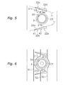
- FIG 4 to FIG 6 are diagrams showing portion C of FIG 1 when each type of water drainage promoting portion is formed in the heat transfer fins 2.
- the slits 32 and 35 are formed in the heat transfer fins 2 in the heat transfer fins 2 .
- the slits 32 and 35 are formed, so as to cross the straight lines L 1 and L 2 in the vertical direction, in gap portions between the guide fins 21a and 21b that are mutually adjacent on the straight line L 1 and between the guide fins 21c and 21d that are mutually adjacent on the straight line L 2 .
- the slits 32 and 35 are given a narrow slit width by forming vertical incisions in the heat transfer fins 2, for example, in order to ensure that the slits 32 and 35 do not, as much as possible, affect heat transfer performance.
- slits 31, 33, 34 and 36 that are the same as the slits 32 and 35 may also be formed in the end portions of the guide fins 21a to 21 d other than the gap portions between the guide fins 21 a and 21 b and between the guide fins 21 c and 21 d.
- the cutouts 42 and 43 are formed in the heat transfer fins 2 that are mutually adjacent on the straight lines L 1 and L 2 , which end portions become lower end portions of the guide fins 21a and 21 b and the guide fins 21c and 21 d (i.e., portions that become lower portions of the guide fins 21 a and 21 b and the guide fins 21 c and 21 d along the direction of gravitational force).
- the cutouts 42 and 43 are formed in the lower end portion of the guide fin 21 b and in the lower end portion of the guide fin 2 1 c.
- the cutouts 42 and 43 are vertical incisions formed in the lower end portions of the guide fins 21 b and 21 c so as to be communicated with the slits 22b and 22c that are formed when forming the guide fins 21 c and 21 c by cutting and raising.
- cutouts 41 and 44 that are the same as the cutouts 42 and 43 may also be formed in the end portions of the guide fins 21 a and 21 d other than the portions that become the lower end portions of the guide fins 21 b and 21 c.
- the water-conducting rib 52 is formed, so as to cross the straight lines L 1 and L 2 in the vertical direction, in gap portions between the guide fins 2 1 a and 21 b that are mutually adjacent on the straight line L 1 and between the guide fins 21 c and 21 d that are mutually adjacent on the straight line L 2 .
- the water-conducting rib 52 is a long and narrow projection that extends upward and is formed by pressing the heat transfer fin 2 surfaces, and the water-conducting rib 52 is formed so as to continuously interconnect, in the vertical direction (i.e., in the direction of gravitational force), the gap portion between the guide fins 21a and 21 b and the gap portion between the guide fins 21 c and 21 d. It will be noted that in the vicinities of the heat transfer tubes 3, the water-conducting rib 52 cannot be straightly extended in the vertical direction, so by forming just the portion thereof in the vicinity of the collar portion 23 in a circular arc shape, a state where the water-conducting rib 52 is continuously formed in substantially the direction of gravitational force can be maintained.
- water-conducting ribs 51 and 53 that are the same as the water-conducting rib 52 may also be formed on the portion on the front side of the guide fins 21a and 21c in the flow direction of the air flow and the portion on the rear side of the guide fins 21 b and 21 d in the flow direction of the air flow other than the gap portion between the guide fins 2 1 a and 21 b and the gap portion between the guide fins 21c and 21 d.
- the ability of the heat transfer fins 2 to drain water can be further raised because the slits 32 and 35, the cutouts 42 and 43, or the water-conducting rib 52 serving as a water drainage promoting portion are formed between the guide fins 21 a and 21b that are mutually adjacent on the straight line L 1 of the heat transfer fins 2 and between the guide fins 2 1 c and 2 1 d that are mutually adjacent on the straight line L 2 .
- FIG 7 is a cross-sectional diagram of the fin tube heat exchanger 101.
- FIG 8 is a cross-sectional diagram along A-A of FIG. 7 .
- FIG 9 is a cross-sectional diagram along B-B of FIG 7 .
- the basic configuration of the fin tube heat exchanger 101 is the same as the configuration of the fin tube heat exchanger 1 of the first embodiment except for guide fins 121 a to 121f of later-described heat transfer fins 102. For this reason, description in regard to the basic configuration of the fin tube heat exchanger 101 will be omitted by changing the reference numerals that relate to the heat transfer fins 102 from the 10s to the 100s.
- plural (in the present embodiment, three) a set of guide fins 121a, 121b and 121c and a set of guide fins 121 d, 121 e and 121f arranged straightly from upstream to downstream in the flow direction of the air flow are formed, by cutting and raising, on the heat transfer fin 2 surfaces on both sides of each of the heat transfer fins 3 (i.e., the lower side and the upper side of each of the heat transfer fins 3).
- Straight lines L 1 and L 2 that hypothetically interconnect the guide fins 121a, 121 b and 121 c and the guide fins 121d, 121 e and 121 f slant with respect to the flow direction of the air flow so as to guide the air flow in the vicinities of the heat transfer tubes 3 to the rear sides of the heat transfer tubes 3 in the flow direction of the air flow.
- attack angles ⁇ 1 and ⁇ 2 that the straight lines L 1 and L 2 form with respect to the flow direction of the air flow are set to be within the range of 10° to 30°.
- each of the guide fins 121 a to 121 f is formed such that its height gradually increases downstream in the flow direction of the air flow.
- each of the guide fins 121 a to 121 f is substantially trapezoidal or substantially triangular (see FIG 9; FIG 9 is a diagram showing the guide fins 121d, 121 e and 121f, but the guide fins 121 a, 121 b and 121c also have the same shape) and is formed such that its maximum height h is less than the height H of collar portions 123.
- slit holes 122a to 122f that are formed in the heat transfer fins 102 when the guide fins 121a to 121 f are cut and raised are disposed on the far sides of the heat transfer fins 3 with the guide fins 121a to 121 f being interposed therebetween.
- the guide fins of the fin tube heat exchanger 1 of the first embodiment had a two-division structure comprising the set of the guide fins 21 a and 21 b and the set of the guide fins 21c and 21d
- the guide fins here have a three-division structure comprising the set of the guide fins 121a, 121b and 121c and the set of the guide fins 121d, 121e and 121f, so the number of gaps between the guide fins for draining drain water occurring on the heat transfer fin 102 surfaces increases. For this reason, the ability to drain drain water can be raised in comparison to the fin tube heat exchanger 1 of the first embodiment.
- slits 131,134,135 and 138, cutouts 141 and 146, or water-conducting ribs 151 and 154 may also be formed in portions other than between the guide fins 121 a and 121 b, between the guide fins 121b and 121 c, between the guide fins 121 d and 121 e, and between the guide fins 121e and 121f.
- a heat transfer promoting effect and water drainability by guide fins can be simultaneously achieved in a fin tube heat exchanger.
Landscapes
- Engineering & Computer Science (AREA)
- Physics & Mathematics (AREA)
- Thermal Sciences (AREA)
- Mechanical Engineering (AREA)
- General Engineering & Computer Science (AREA)
- Geometry (AREA)
- Heat-Exchange Devices With Radiators And Conduit Assemblies (AREA)
- Details Of Fluid Heaters (AREA)
Abstract
Description
- The present invention relates to a fin tube heat exchanger, and in particular to a fin tube heat exchanger having heat transfer fins disposed in an air flow and plural heat transfer tubes that are inserted in the heat transfer fins and disposed in a direction substantially orthogonal to a flow direction of the air flow.
- Conventionally, fin tube heat exchangers (i.e., cross fin and tube heat exchangers) having heat transfer fins disposed in an air flow and plural heat transfer tubes that are inserted in the heat transfer fins and disposed in a direction substantially orthogonal to a flow direction of the air flow have been widely used in air conditioners and the like.
- In such fin tube heat exchangers, as a heat transfer promoting technique for the purpose of reducing dead water regions formed in the portions of the heat transfer tubes in the heat transfer fins downstream in the flow direction of the air flow and for the purpose of renewing the boundary layers in the heat transfer fins, a technique of forming, by cutting and raising and in positions on the heat transfer fin surfaces on both sides of the heat transfer tubes, guide fins that become larger and open upstream in the flow direction of the air flow has been employed (see Patent Document 1).
- Japanese Patent Application Publication (
JP-A) No. 61-110889 - However, when a fin tube heat exchanger in which the aforementioned guide fins are employed is used as an evaporator of a heat medium such as refrigerant which uses air as a heat source such as represented by air conditioners and the like, a problem arises in that drain water occurring due to heat exchange between the air and the heat medium accumulates on the guide fins and increases ventilation resistance. Further, when a fin tube heat exchanger in which the aforementioned guide fins are employed is used as an outdoor heat exchanger configuring an outdoor unit of an air conditioner, a problem arises in that, although sometimes frost occurring on the heat transfer fin surfaces is removed by defrosting operation, water drainability is lowered in this case.
- It is an object of the present invention to simultaneously achieve a heat transfer promoting effect and water drainability by guide fins in a fin tube heat exchanger.
- A fin tube heat exchanger pertaining to a first invention comprises: heat transfer fins disposed in an air flow; and plural heat transfer tubes that are inserted in the heat transfer fins and disposed in a direction substantially orthogonal to a flow direction of the air flow. On the heat transfer fins, plural guide fins arranged straightly from upstream to downstream in the flow direction of the air flow are formed, by cutting and raising, on the heat transfer fin surfaces on both sides of the heat transfer tubes. Straight lines that hypothetically interconnect the plural guide fins slant with respect to the flow direction of the air flow so as to guide the air flow in the vicinities of the heat transfer tubes to rear sides of the heat transfer tubes in the flow direction of the air flow
- In this fin tube heat exchanger, the guide fins are plurally divided from upstream to downstream in the flow direction of the air flow, and the plural guide fins slant with respect to the flow direction of the air flow so as to guide the air flow in the vicinities of the heat transfer tubes to rear sides of the heat transfer tubes in the flow direction of the air flow, so mainly the effect of renewing the boundary layers can be reliably obtained by the guide fins of the plural guide fins that are disposed on the front sides of the heat transfer fins in the flow direction of the air flow and the effect of reducing dead water regions formed of the rear sides of the heat transfer fins in the flow direction of the air flow can be obtained by the guide fins that are disposed on the rear sides of the heat transfer fins in the flow direction of the air flow, and it can be made easier for drain water occurring on the heat transfer fin surfaces to be drained from gaps between the guide fins. Thus, a heat transfer promoting effect by the guide fins can be obtained without being affected by drain water occurring on the heat transfer fin surfaces.
- Moreover, because the plural guide fins are straightly arranged from upstream to downstream in the flow direction of the air flow, the guide fins of the plural guide fins that are disposed on the rear sides of the heat transfer fins in the flow direction of the air flow have the same inclination as the guide fins that are disposed on the front sides in the flow direction of the air flow, so not only do they reduce dead water regions formed in portions on the rear sides of the heat transfer tubes in the flow direction of the air flow, but they can prevent new dead water regions from being formed on the backs of the guide fins.
- As described above, in the fin tube heat exchanger pertaining to the present invention, the effect of promoting heat transfer by the guide fins can be obtained without being affected by drain water occurring on the heat transfer fin surfaces, and new dead water regions can be prevented from being formed on the backs of the guide fins, so a heat transfer promoting effect and water drainability by the guide fins can be simultaneously achieved.
- A fin tube heat exchanger pertaining to a second invention is the fin tube heat exchanger pertaining to the first invention, wherein the height of each of the guide fins gradually increases downstream in the flow direction of the air flow.
- In this fin tube heat exchanger, by giving each of the guide fins a shape whose height gradually increases downstream in the flow direction of the air flow, vertical vortexes can be created on the back of each of the guide fins, so that the heat transfer promoting effect by the guide fins can be further raised.
- A fin tube heat exchanger pertaining to a third invention is the fin tube heat exchanger pertaining to the first or second invention, wherein a water drainage promoting portion for causing water accumulating between the guide fins that are mutually adjacent on the straight lines to flow downward is formed in the heat transfer fins.
- In this fin tube heat exchanger, the water drainage promoting portion is formed between the guide fins, so the ability of the guide fins to drain water can be further raised.
- A fin tube heat exchanger pertaining to a fourth invention is the fin tube heat exchanger pertaining to the third invention, wherein the water drainage promoting portion is a slit formed between the guide fins that are mutually adjacent on the straight lines.
- A fin tube heat exchanger pertaining to a fifth invention is the fin tube heat exchanger pertaining to the third invention, wherein the water drainage promoting portion is a cutout formed in end portions of the guide fins that are mutually adjacent on the straight lines, which end portions are portions that become lower end portions of the guide fins.
- A fin tube heat exchanger pertaining to a sixth invention is the fin tube heat exchanger pertaining to the third invention, wherein the water drainage promoting portion is a water-conducting rib formed between the guide fins that are mutually adjacent on the straight lines.
-
-
FIG 1 is a cross-sectional diagram of a fin tube heat exchanger pertaining to a first embodiment of the present invention. -
FIG 2 is a cross-sectional diagram along A-A ofFIG 1 . -
FIG 3 is a cross-sectional diagram along B-B ofFIG 1 . -
FIG 4 is a diagram showing a fin tube heat exchanger pertaining to a modification of the first embodiment, the diagram showing portion C ofFIG 1 . -
FIG 5 is a diagram showing a fin tube heat exchanger pertaining to a modification of the first embodiment, the diagram showing portion C ofFIG 1 . -
FIG 6 is a diagram showing a fin tube heat exchanger pertaining to a modification of the first embodiment, the diagram showing portion C ofFIG 1 . -
FIG 7 is a cross-sectional diagram of a fin tube heat exchanger pertaining to a second embodiment of the present invention. -
FIG 8 is a cross-sectional diagram along A-A ofFIG 7 . -
FIG 9 is a cross-sectional diagram along B-B ofFIG 7 . -
FIG 10 is a diagram showing a fin tube heat exchanger pertaining to a modification of the second embodiment, the diagram showing portion C ofFIG 7 . -
FIG 11 is a diagram showing a fin tube heat exchanger pertaining to a modification of the second embodiment, the diagram showing portion C ofFIG 7 . -
FIG 12 is a diagram showing a fin tube heat exchanger pertaining to a modification of the second embodiment, the diagram showing portion C ofFIG 7 . -
- 1, 101
- Fin Tube Heat Exchangers
- 2, 102
- Heat Transfer Fins
- 3
- Heat Transfer Tube
- 21a to 21d, 121a to 121f
- Guide Fins
- 32, 35, 132, 133, 136, 137
- Slits (Water Drainage Promoting Portions)
- 42, 43, 142, 143, 144, 145
- Cutouts (Water Drainage Promoting Portions)
- 52,151,154
- Water-conducting Ribs
- Below, embodiments of a fin tube heat exchanger pertaining to the present invention will be described on the basis of the drawings.
- In
FIG 1 to FIG 3 , there are shown relevant portions of a fin tube heat exchanger 1 pertaining to a first embodiment of the present invention. Here,FIG 1 is a cross-sectional diagram of the fin tube heat exchanger 1.FIG 2 is a cross-sectional diagram along A-A ofFIG 1 .FIG 3 is a cross-sectional diagram along B-B ofFIG 1 . - The fin tube heat exchanger 1 is a cross fin and tube heat exchanger and is mainly disposed with plural plate-shaped
heat transfer fins 2 and pluralheat transfer tubes 3. Theheat transfer fins 2 are disposed so as to be arranged in a plate thickness direction in a state where the planar direction thereof is generally along a flow direction of an air flow such as that of air. Plural throughholes 2a are formed in theheat transfer fins 2 at intervals in a direction substantially orthogonal to the flow direction of the air flow. Portions around the throughholes 2a serve asannular collar portions 23 that project towards one side in the plate thickness direction of theheat transfer fins 2. Thecollar portions 23 contact surfaces of theheat transfer fins 2 adjacent in the plate thickness direction that are opposite of surfaces where thecollar portions 23 are formed, such that a predetermined interval H is ensured between each of theheat transfer fins 2 in the plate thickness direction. Theheat transfer tubes 3 are tube members inside of which a heat medium such as refrigerant flows; theheat transfer tubes 3 are inserted in the pluralheat transfer fins 2, which are disposed so as to be arranged in the plate thickness direction, and disposed in a direction substantially orthogonal to the flow direction of the air flow. Specifically, theheat transfer tubes 3 penetrate the throughholes 2a formed in theheat transfer fins 2 and tightly contact the inner surfaces of thecollar portions 23 as a result of tube expansion work during assembly of the fin tube heat exchanger 1. - Further, the fin tube heat exchanger 1 of the present embodiment is used in a state where the arranging direction of the plural
heat transfer tubes 3 is in a substantially vertical direction. For this reason, the air flow flows so as to cross through the fin tube heat exchanger 1 in a substantially horizontal direction. It will be noted that in the following description, when language such as "upper side" or "upward" and "lower side" or "downward" is used, this will indicate the arranging direction of theheat transfer tubes 3. - Next, the detailed shape of the
heat transfer fins 2 used in the fin tube heat exchanger 1 of the present embodiment will be described. - On the
heat transfer fins 2, plural (in the present embodiment, two) a set ofguide fins guide fins heat transfer fin 2 surfaces on both sides of each of the heat transfer fins 3 (i.e., the lower side and the upper side of each of the heat transfer fins 3). Straight lines L1 and L2 that hypothetically interconnect theguide fins guide fins heat transfer tubes 3 to rear sides of theheat transfer tubes 3 in the flow direction of the air flow. Here, attack angles α1 and α2 that the straight lines L1 and L2 form with respect to the flow direction of the air flow are set to be within the range of 10° to 30°. - Further, each of the
guide fins 21a to 2 1 d is formed such that its height gradually increases downstream in the flow direction of the air flow In the present embodiment, each of theguide fins 2 1 a to 2 1 d is substantially trapezoidal or substantially triangular (seeFIG 3; FIG 3 is a diagram showing theguide fins guide fins collar portions 23. Further, slitholes 22a to 22d that are formed in theheat transfer fins 2 when theguide fins 21 a to 21 d are cut and raised are disposed on the far sides of theheat transfer fins 3 with theguide fins 21 a to 21 d being interposed therebetween. - In the fin tube heat exchanger 1 configured as described above, the guide fins formed on both sides of each of the heat transfer tubes 3 are divided into the plural (in the present embodiment, two) the set of the guide fins 21 a and 21b and the set of the guide fins 21c and 2 1 d from upstream to downstream in the flow direction of the air flow, and the set of the guide fins 21 a and 21b and the set of the guide fins 21 c and 21 d slant with respect to the flow direction of the air flow so as to guide the air flow in the vicinities of the heat transfer tubes 3 to the rear sides of the heat transfer tubes 3 in the flow direction of the air flow, so mainly the effect of renewing the boundary layers can be reliably obtained by the guide fins 21 a and 21 c of the guide fins 21 a to 21 d that are disposed on the front sides of the heat transfer fins 2 in the flow direction of the air flow and the effect of reducing dead water regions formed on portions of the rear sides of the heat transfer fins 3 in the flow direction of the air flow can be obtained by the guide fins 21b and 21d that are disposed on the rear sides of the heat transfer fins 2 in the flow direction of the air flow, and it can be made easier for drain water occurring on the heat transfer fin 2 surfaces to be drained from between the guide fins 21 a and 21 b and between the guide fins 21 c and 21 d. Thus, a heat transfer promoting effect by the
guide fins 21 a to 21 d can be obtained without being affected by drain water occurring on theheat transfer fin 2 surfaces. - Moreover, because the
guide fins guide fins guide fins guide fins 21 a to 21 d that are disposed on the rear sides of theheat transfer fins 2 in the flow direction of the air flow have the same inclination as theguide fins heat transfer tubes 3 in the flow direction of the air flow, but they can prevent new dead water regions from being formed on the backs of theguide fins 2 1 b and 2 1 d. - As described above, in the fin tube heat exchanger 1 of the present embodiment, a heat transfer promoting effect by the
guide fins 21 a to 21 d can be obtained without being affected by drain water occurring on theheat transfer fin 2 surfaces, and new dead water regions can be prevented from being formed on the backs of theguide fins - Further, in this fin tube heat exchanger 1, by giving each of the
guide fins 21 a to 21 d a shape whose height gradually increases downstream in the flow direction of the air flow, vertical vortexes can be formed on the back of each of theguide fins 21 a to 21 d, so the heat transfer promoting effect by each of theguide fins 21 a to 21 d can be further raised. - In the aforementioned fin tube heat exchanger 1, slits 32 and 35 (see
FIG 4 ),cutouts 42 and 43 (seeFIG 5 ), or a water-conducting rib 52 (seeFIG 6 ) serving as a water drainage promoting portion to cause water accumulating between theguide fins guide fins heat transfer fin 2 surfaces to be drained from gaps between theguide fins guide fins FIG 4 to FIG 6 are diagrams showing portion C ofFIG 1 when each type of water drainage promoting portion is formed in theheat transfer fins 2. - First, a case where the
slits heat transfer fins 2 will be described usingFIG 4 . In the present modification, theslits guide fins guide fins slits heat transfer fins 2, for example, in order to ensure that theslits slits guide fins 21a to 21 d other than the gap portions between theguide fins guide fins - Next, a case where the
cutouts heat transfer fins 2 will be described usingFIG 5 . In the present modification, thecutouts guide fins guide fins guide fins guide fins guide fins guide fins cutouts guide fin 21 b and in the lower end portion of theguide fin 2 1 c. Here, thecutouts guide fins slits guide fins cutouts cutouts guide fins guide fins - Next, a case where the water-conducting
rib 52 is formed on theheat transfer fins 2 will be described usingFIG 6 . In the present modification, the water-conductingrib 52 is formed, so as to cross the straight lines L1 and L2 in the vertical direction, in gap portions between theguide fins 2 1 a and 21 b that are mutually adjacent on the straight line L1 and between theguide fins rib 52 is a long and narrow projection that extends upward and is formed by pressing theheat transfer fin 2 surfaces, and the water-conductingrib 52 is formed so as to continuously interconnect, in the vertical direction (i.e., in the direction of gravitational force), the gap portion between theguide fins guide fins heat transfer tubes 3, the water-conductingrib 52 cannot be straightly extended in the vertical direction, so by forming just the portion thereof in the vicinity of thecollar portion 23 in a circular arc shape, a state where the water-conductingrib 52 is continuously formed in substantially the direction of gravitational force can be maintained. Further, water-conductingribs rib 52 may also be formed on the portion on the front side of theguide fins guide fins guide fins 2 1 a and 21 b and the gap portion between theguide fins - As described above, in the fin tube heat exchanger 1 of the present modification, the ability of the
heat transfer fins 2 to drain water can be further raised because theslits cutouts rib 52 serving as a water drainage promoting portion are formed between theguide fins heat transfer fins 2 and between theguide fins 2 1 c and 2 1 d that are mutually adjacent on the straight line L2. - In
FIG 7 to FIG 9 , there are shown relevant portions of a fintube heat exchanger 101 pertaining to a second embodiment of the present invention. Here,FIG 7 is a cross-sectional diagram of the fintube heat exchanger 101.FIG 8 is a cross-sectional diagram along A-A ofFIG. 7 .FIG 9 is a cross-sectional diagram along B-B ofFIG 7 . - The basic configuration of the fin
tube heat exchanger 101 is the same as the configuration of the fin tube heat exchanger 1 of the first embodiment except forguide fins 121 a to 121f of later-describedheat transfer fins 102. For this reason, description in regard to the basic configuration of the fintube heat exchanger 101 will be omitted by changing the reference numerals that relate to theheat transfer fins 102 from the 10s to the 100s. - Next, the detailed shape of the
heat transfer fins 102 used in the fintube heat exchanger 101 of the present embodiment will be described. - On the
heat transfer fins 102, plural (in the present embodiment, three) a set ofguide fins guide fins heat transfer fin 2 surfaces on both sides of each of the heat transfer fins 3 (i.e., the lower side and the upper side of each of the heat transfer fins 3). Straight lines L1 and L2 that hypothetically interconnect theguide fins guide fins heat transfer tubes 3 to the rear sides of theheat transfer tubes 3 in the flow direction of the air flow. Here, attack angles α1 and α2 that the straight lines L1 and L2 form with respect to the flow direction of the air flow are set to be within the range of 10° to 30°. - Further, each of the
guide fins 121 a to 121 f is formed such that its height gradually increases downstream in the flow direction of the air flow. In the present embodiment, each of theguide fins 121 a to 121 f is substantially trapezoidal or substantially triangular (seeFIG 9; FIG 9 is a diagram showing theguide fins guide fins collar portions 123. Further, slitholes 122a to 122f that are formed in theheat transfer fins 102 when theguide fins 121a to 121 f are cut and raised are disposed on the far sides of theheat transfer fins 3 with theguide fins 121a to 121 f being interposed therebetween. - As described above, in the fin
tube heat exchanger 101 of the present embodiment configured as described above, whereas the guide fins of the fin tube heat exchanger 1 of the first embodiment had a two-division structure comprising the set of theguide fins guide fins guide fins guide fins heat transfer fin 102 surfaces increases. For this reason, the ability to drain drain water can be raised in comparison to the fin tube heat exchanger 1 of the first embodiment. - In the aforementioned fin
tube heat exchanger 101 also, similar to the fin tube heat exchanger 1 of the first embodiment, slits 132, 133, 136 and 137 (seeFIG 10 ),cutouts FIG 11 ), or water-conductingribs 152 and 153 (seeFIG 12 ) serving as a water drainage promoting portion that causes water accumulating between theguide fins guide fins guide fins guide fins heat transfer fin 102 surfaces to be drained from gaps between theguide fins guide fins guide fins guide fins FIG 10 to FIG 12 are diagrams showing portion C ofFIG 7 when each type of water drainage promoting portion is formed in theheat transfer fins 102. - It will be noted that, because the shapes and the like of the slits, the cutouts and the water-conducting ribs are the same as those of the
slits cutouts ribs 52 pertaining to the modifications of the first embodiment, description thereof will be omitted. Further, in this fintube heat exchanger 101 also, similar to the fin tube heat exchanger 1 pertaining to the modifications of the first embodiment, slits 131,134,135 and 138,cutouts ribs guide fins guide fins guide fins guide fins - Embodiments of the present invention have been described above on the basis of the drawings, but the specific configurations thereof are not limited to these embodiments and are alterable in a range that does not depart from the gist of the invention.
- By utilizing the present invention, a heat transfer promoting effect and water drainability by guide fins can be simultaneously achieved in a fin tube heat exchanger.
Claims (6)
- A fin tube heat exchanger (1, 101) comprising:heat transfer fins (2, 102) disposed in an air flow; andplural heat transfer tubes (3) that are inserted in the heat transfer fins and disposed in a direction substantially orthogonal to a flow direction of the air flow,whereinon the heat transfer fins, plural guide fins (21a to 21d, 121 a to 121f) arranged straightly from upstream to downstream in the flow direction of the air flow are formed, by cutting and raising, on the heat transfer fin surfaces on both sides of the heat transfer tubes, andstraight lines (L1, L2) that hypothetically interconnect the plural guide fins slant with respect to the flow direction of the air flow so as to guide the air flow in the vicinities of the heat transfer tubes to rear sides of the heat transfer tubes in the flow direction of the air flow.
- The fin tube heat exchanger (1, 101) of claim 1, wherein the height of each of the guide fins (21 a to 21d, 121 a to 121f) gradually increases downstream in the flow direction of the air flow.
- The fin tube heat exchanger (1, 101) of claim 1 or 2, wherein a water drainage promoting portion for causing water accumulating between the guide fins (21a to 21d, 121a to 121f) that are mutually adjacent on the straight lines (L1, L2) to flow downward is formed in the heat transfer fins (2, 102).
- The fin tube heat exchanger (1, 101) of claim 3, wherein the water drainage promoting portion is a slit (32,35,132,133,136,137) formed between the guide fins (21a to 21d, 121a to 121f) that are mutually adjacent on the straight lines (L1, L2).
- The fin tube heat exchanger (1, 101) of claim 3, wherein the water drainage promoting portion is a cutout (42, 43, 142, 143, 144, 145) formed in end portions (21 a to 21d, 121a to 121f) of the guide fins that are mutually adjacent on the straight lines (L1, L2), which end portions are portions that become lower end portions of the guide fins.
- The fin tube heat exchanger (1, 101) of claim 3, wherein the water drainage promoting portion is a water-conducting rib (52, 151, 154) formed between the guide fins (21a to 21d, 121a to 121f) that are mutually adjacent on the straight lines (L1, L2).
Applications Claiming Priority (2)
| Application Number | Priority Date | Filing Date | Title |
|---|---|---|---|
| JP2005194254A JP2007010279A (en) | 2005-07-01 | 2005-07-01 | Finned tube heat exchanger |
| PCT/JP2006/312716 WO2007004457A1 (en) | 2005-07-01 | 2006-06-26 | Fin tube heat exchanger |
Publications (3)
| Publication Number | Publication Date |
|---|---|
| EP1906129A1 true EP1906129A1 (en) | 2008-04-02 |
| EP1906129A4 EP1906129A4 (en) | 2010-08-11 |
| EP1906129B1 EP1906129B1 (en) | 2011-09-07 |
Family
ID=37604326
Family Applications (1)
| Application Number | Title | Priority Date | Filing Date |
|---|---|---|---|
| EP06767333A Not-in-force EP1906129B1 (en) | 2005-07-01 | 2006-06-26 | Fin tube heat exchanger |
Country Status (8)
| Country | Link |
|---|---|
| US (1) | US20100175864A1 (en) |
| EP (1) | EP1906129B1 (en) |
| JP (1) | JP2007010279A (en) |
| KR (1) | KR100973225B1 (en) |
| CN (1) | CN100554855C (en) |
| AU (1) | AU2006266965B2 (en) |
| ES (1) | ES2370795T3 (en) |
| WO (1) | WO2007004457A1 (en) |
Cited By (2)
| Publication number | Priority date | Publication date | Assignee | Title |
|---|---|---|---|---|
| AU2009252652B2 (en) * | 2008-05-27 | 2012-05-24 | Daikin Industries, Ltd. | Fin tube type heat exchanger |
| CN112964112A (en) * | 2021-03-25 | 2021-06-15 | 山东西努克机械科技有限公司 | Efficient radiating fin |
Families Citing this family (12)
| Publication number | Priority date | Publication date | Assignee | Title |
|---|---|---|---|---|
| JP5162929B2 (en) * | 2007-03-14 | 2013-03-13 | ダイキン工業株式会社 | Finned tube heat exchanger |
| JP2008232448A (en) * | 2007-03-16 | 2008-10-02 | Daikin Ind Ltd | Finned tube heat exchanger and air conditioner |
| JP4293252B2 (en) * | 2007-03-19 | 2009-07-08 | ダイキン工業株式会社 | Fin for heat exchanger, guide and method of using the same |
| JP2008249298A (en) * | 2007-03-30 | 2008-10-16 | Daikin Ind Ltd | Finned tube heat exchanger |
| JP5304025B2 (en) * | 2008-05-27 | 2013-10-02 | ダイキン工業株式会社 | Finned tube heat exchanger |
| CN102374816A (en) * | 2011-11-09 | 2012-03-14 | 海信(山东)空调有限公司 | Ring-wing bridge-type heat-exchanger fin, heat exchanger and air conditioner |
| CN106461350A (en) * | 2014-05-15 | 2017-02-22 | 三菱电机株式会社 | Heat exchanger and refrigeration cycle device having the heat exchanger |
| CN105758246B (en) * | 2014-12-15 | 2019-06-11 | 浙江盾安人工环境股份有限公司 | Heat Exchanger Fins and Heat Exchangers |
| US10005413B2 (en) | 2016-10-05 | 2018-06-26 | Toyota Motor Engineering & Manufacturing North America, Inc. | Vehicles including front grille assemblies with air flow director fins |
| JP6680225B2 (en) * | 2017-01-19 | 2020-04-15 | 株式会社デンソー | Heat exchanger and method for manufacturing heat exchanger |
| US11236951B2 (en) * | 2018-12-06 | 2022-02-01 | Johnson Controls Technology Company | Heat exchanger fin surface enhancement |
| WO2022045667A1 (en) * | 2020-08-31 | 2022-03-03 | Samsung Electronics Co., Ltd. | Heat exchanger and air conditioner using the heat exchanger |
Family Cites Families (17)
| Publication number | Priority date | Publication date | Assignee | Title |
|---|---|---|---|---|
| JPS59185992A (en) * | 1983-04-06 | 1984-10-22 | Mitsubishi Electric Corp | Heat exchanger |
| JPS59208396A (en) * | 1983-05-11 | 1984-11-26 | Mitsubishi Electric Corp | Heat exchanger |
| JPS59215596A (en) * | 1983-05-19 | 1984-12-05 | Mitsubishi Electric Corp | Heat exchanger |
| JPS6020094A (en) * | 1983-07-13 | 1985-02-01 | Mitsubishi Electric Corp | Heat exchanger |
| JPS616590A (en) * | 1984-06-19 | 1986-01-13 | Matsushita Electric Ind Co Ltd | Heat exchanger with fins |
| KR890002903B1 (en) * | 1984-09-04 | 1989-08-08 | 마쯔시다덴기산교 가부시기가이샤 | heat transmitter |
| DE3737217C3 (en) * | 1987-11-03 | 1994-09-01 | Gea Luftkuehler Happel Gmbh | Heat exchanger tube |
| JP2798959B2 (en) * | 1989-03-30 | 1998-09-17 | 株式会社東芝 | Heat exchanger |
| JPH05164489A (en) * | 1991-12-12 | 1993-06-29 | Daikin Ind Ltd | Heat exchanger with fin |
| JPH09159390A (en) * | 1995-12-06 | 1997-06-20 | Matsushita Electric Ind Co Ltd | Heat exchanger for water heater |
| JPH109786A (en) * | 1996-06-21 | 1998-01-16 | Matsushita Refrig Co Ltd | Finned heat exchanger |
| KR100210073B1 (en) * | 1996-07-09 | 1999-07-15 | 윤종용 | Heat exchanger of air conditioner |
| JPH10332291A (en) * | 1997-05-30 | 1998-12-15 | Mitsubishi Heavy Ind Ltd | Fin and tube type heat-exchanger |
| JP2001147087A (en) * | 1999-11-19 | 2001-05-29 | Fujitsu General Ltd | Fin tube type heat exchanger |
| KR100363317B1 (en) * | 2000-03-31 | 2002-12-02 | 만도공조 주식회사 | Radiation fin of heat exchanger |
| CA2391077A1 (en) * | 2001-06-28 | 2002-12-28 | York International Corporation | High-v plate fin for a heat exchanger and a method of manufacturing |
| US7337831B2 (en) * | 2001-08-10 | 2008-03-04 | Yokohama Tlo Company Ltd. | Heat transfer device |
-
2005
- 2005-07-01 JP JP2005194254A patent/JP2007010279A/en active Pending
-
2006
- 2006-06-26 US US11/917,994 patent/US20100175864A1/en not_active Abandoned
- 2006-06-26 ES ES06767333T patent/ES2370795T3/en active Active
- 2006-06-26 EP EP06767333A patent/EP1906129B1/en not_active Not-in-force
- 2006-06-26 CN CNB2006800229226A patent/CN100554855C/en not_active Expired - Fee Related
- 2006-06-26 AU AU2006266965A patent/AU2006266965B2/en not_active Ceased
- 2006-06-26 KR KR1020077030246A patent/KR100973225B1/en not_active Expired - Fee Related
- 2006-06-26 WO PCT/JP2006/312716 patent/WO2007004457A1/en not_active Ceased
Cited By (2)
| Publication number | Priority date | Publication date | Assignee | Title |
|---|---|---|---|---|
| AU2009252652B2 (en) * | 2008-05-27 | 2012-05-24 | Daikin Industries, Ltd. | Fin tube type heat exchanger |
| CN112964112A (en) * | 2021-03-25 | 2021-06-15 | 山东西努克机械科技有限公司 | Efficient radiating fin |
Also Published As
| Publication number | Publication date |
|---|---|
| ES2370795T3 (en) | 2011-12-22 |
| KR100973225B1 (en) | 2010-07-30 |
| EP1906129B1 (en) | 2011-09-07 |
| AU2006266965A1 (en) | 2007-01-11 |
| KR20080011445A (en) | 2008-02-04 |
| US20100175864A1 (en) | 2010-07-15 |
| WO2007004457A1 (en) | 2007-01-11 |
| CN101208575A (en) | 2008-06-25 |
| WO2007004457A8 (en) | 2008-01-31 |
| JP2007010279A (en) | 2007-01-18 |
| AU2006266965B2 (en) | 2009-08-13 |
| EP1906129A4 (en) | 2010-08-11 |
| CN100554855C (en) | 2009-10-28 |
Similar Documents
| Publication | Publication Date | Title |
|---|---|---|
| EP1906129B1 (en) | Fin tube heat exchanger | |
| US8613307B2 (en) | Finned tube heat exchanger | |
| EP3018439B1 (en) | Fin tube heat exchanger | |
| EP2048465B1 (en) | Heat exchanger and air conditioner | |
| EP2314973B1 (en) | Fin-tube heat exchanger | |
| CN107407534A (en) | Heat exchanger and air conditioner | |
| JP2010019534A (en) | Heat exchanger | |
| JP6330577B2 (en) | Fin and tube heat exchanger | |
| CN110425904B (en) | Flat fin, microchannel heat exchanger, and air conditioner | |
| EP2843345B1 (en) | Fin-tube heat exchanger and refrigeration cycle device using same | |
| JP2009204279A (en) | Heat exchanger | |
| US20190120557A1 (en) | Heat exchanger | |
| JP2006038311A (en) | Finned tube heat exchanger | |
| EP2224198A1 (en) | Fin and tube type heat exchanger | |
| JP2010255974A (en) | Heat exchanger | |
| JP2007017042A (en) | Heat exchanger | |
| JP2008249298A (en) | Finned tube heat exchanger | |
| JP4940871B2 (en) | Finned tube heat exchanger | |
| CN103791660B (en) | Fin-tube heat exchanger | |
| JP3863034B2 (en) | Heat exchanger | |
| JP2014020582A (en) | Fin tube type heat exchanger | |
| JPH05164487A (en) | Heat exchanger with fins | |
| JP2006138622A (en) | Corrugate fin and evaporator | |
| KR102115250B1 (en) | Evaporator for Motor Vehicle | |
| JP6236622B2 (en) | Finned heat exchanger |
Legal Events
| Date | Code | Title | Description |
|---|---|---|---|
| PUAI | Public reference made under article 153(3) epc to a published international application that has entered the european phase |
Free format text: ORIGINAL CODE: 0009012 |
|
| 17P | Request for examination filed |
Effective date: 20080130 |
|
| AK | Designated contracting states |
Kind code of ref document: A1 Designated state(s): AT BE BG CH CY CZ DE DK EE ES FI FR GB GR HU IE IS IT LI LT LU LV MC NL PL PT RO SE SI SK TR |
|
| DAX | Request for extension of the european patent (deleted) | ||
| DAX | Request for extension of the european patent (deleted) | ||
| A4 | Supplementary search report drawn up and despatched |
Effective date: 20100708 |
|
| GRAP | Despatch of communication of intention to grant a patent |
Free format text: ORIGINAL CODE: EPIDOSNIGR1 |
|
| RIC1 | Information provided on ipc code assigned before grant |
Ipc: F28F 1/32 20060101AFI20110204BHEP |
|
| RIN1 | Information on inventor provided before grant (corrected) |
Inventor name: FUJINO, HIROKAZUC/O KANAOKA FACTORY Inventor name: KASAI, KAZUSHIGEC/O KANAOKA FACTORY, SAKAI PLANT Inventor name: KAMADA, TOSHIMITSUC/O KANAOKA FACTORY SAKAI PLANT Inventor name: KIM, HYUNYOUNGC/O KANAOKA FACTORY, SAKAI PLANT |
|
| GRAS | Grant fee paid |
Free format text: ORIGINAL CODE: EPIDOSNIGR3 |
|
| GRAA | (expected) grant |
Free format text: ORIGINAL CODE: 0009210 |
|
| REG | Reference to a national code |
Ref country code: GB Ref legal event code: FG4D |
|
| REG | Reference to a national code |
Ref country code: CH Ref legal event code: EP |
|
| REG | Reference to a national code |
Ref country code: IE Ref legal event code: FG4D |
|
| REG | Reference to a national code |
Ref country code: DE Ref legal event code: R096 Ref document number: 602006024241 Country of ref document: DE Effective date: 20111103 |
|
| REG | Reference to a national code |
Ref country code: ES Ref legal event code: FG2A Ref document number: 2370795 Country of ref document: ES Kind code of ref document: T3 Effective date: 20111222 |
|
| REG | Reference to a national code |
Ref country code: NL Ref legal event code: VDEP Effective date: 20110907 |
|
| PG25 | Lapsed in a contracting state [announced via postgrant information from national office to epo] |
Ref country code: FI Free format text: LAPSE BECAUSE OF FAILURE TO SUBMIT A TRANSLATION OF THE DESCRIPTION OR TO PAY THE FEE WITHIN THE PRESCRIBED TIME-LIMIT Effective date: 20110907 Ref country code: SE Free format text: LAPSE BECAUSE OF FAILURE TO SUBMIT A TRANSLATION OF THE DESCRIPTION OR TO PAY THE FEE WITHIN THE PRESCRIBED TIME-LIMIT Effective date: 20110907 Ref country code: LT Free format text: LAPSE BECAUSE OF FAILURE TO SUBMIT A TRANSLATION OF THE DESCRIPTION OR TO PAY THE FEE WITHIN THE PRESCRIBED TIME-LIMIT Effective date: 20110907 |
|
| LTIE | Lt: invalidation of european patent or patent extension |
Effective date: 20110907 |
|
| PG25 | Lapsed in a contracting state [announced via postgrant information from national office to epo] |
Ref country code: AT Free format text: LAPSE BECAUSE OF FAILURE TO SUBMIT A TRANSLATION OF THE DESCRIPTION OR TO PAY THE FEE WITHIN THE PRESCRIBED TIME-LIMIT Effective date: 20110907 Ref country code: LV Free format text: LAPSE BECAUSE OF FAILURE TO SUBMIT A TRANSLATION OF THE DESCRIPTION OR TO PAY THE FEE WITHIN THE PRESCRIBED TIME-LIMIT Effective date: 20110907 Ref country code: GR Free format text: LAPSE BECAUSE OF FAILURE TO SUBMIT A TRANSLATION OF THE DESCRIPTION OR TO PAY THE FEE WITHIN THE PRESCRIBED TIME-LIMIT Effective date: 20111208 Ref country code: SI Free format text: LAPSE BECAUSE OF FAILURE TO SUBMIT A TRANSLATION OF THE DESCRIPTION OR TO PAY THE FEE WITHIN THE PRESCRIBED TIME-LIMIT Effective date: 20110907 Ref country code: CY Free format text: LAPSE BECAUSE OF FAILURE TO SUBMIT A TRANSLATION OF THE DESCRIPTION OR TO PAY THE FEE WITHIN THE PRESCRIBED TIME-LIMIT Effective date: 20110907 |
|
| REG | Reference to a national code |
Ref country code: AT Ref legal event code: MK05 Ref document number: 523749 Country of ref document: AT Kind code of ref document: T Effective date: 20110907 |
|
| PG25 | Lapsed in a contracting state [announced via postgrant information from national office to epo] |
Ref country code: BE Free format text: LAPSE BECAUSE OF FAILURE TO SUBMIT A TRANSLATION OF THE DESCRIPTION OR TO PAY THE FEE WITHIN THE PRESCRIBED TIME-LIMIT Effective date: 20110907 |
|
| PG25 | Lapsed in a contracting state [announced via postgrant information from national office to epo] |
Ref country code: SK Free format text: LAPSE BECAUSE OF FAILURE TO SUBMIT A TRANSLATION OF THE DESCRIPTION OR TO PAY THE FEE WITHIN THE PRESCRIBED TIME-LIMIT Effective date: 20110907 Ref country code: CZ Free format text: LAPSE BECAUSE OF FAILURE TO SUBMIT A TRANSLATION OF THE DESCRIPTION OR TO PAY THE FEE WITHIN THE PRESCRIBED TIME-LIMIT Effective date: 20110907 Ref country code: IS Free format text: LAPSE BECAUSE OF FAILURE TO SUBMIT A TRANSLATION OF THE DESCRIPTION OR TO PAY THE FEE WITHIN THE PRESCRIBED TIME-LIMIT Effective date: 20120107 |
|
| PG25 | Lapsed in a contracting state [announced via postgrant information from national office to epo] |
Ref country code: PT Free format text: LAPSE BECAUSE OF FAILURE TO SUBMIT A TRANSLATION OF THE DESCRIPTION OR TO PAY THE FEE WITHIN THE PRESCRIBED TIME-LIMIT Effective date: 20120109 Ref country code: RO Free format text: LAPSE BECAUSE OF FAILURE TO SUBMIT A TRANSLATION OF THE DESCRIPTION OR TO PAY THE FEE WITHIN THE PRESCRIBED TIME-LIMIT Effective date: 20110907 Ref country code: PL Free format text: LAPSE BECAUSE OF FAILURE TO SUBMIT A TRANSLATION OF THE DESCRIPTION OR TO PAY THE FEE WITHIN THE PRESCRIBED TIME-LIMIT Effective date: 20110907 Ref country code: NL Free format text: LAPSE BECAUSE OF FAILURE TO SUBMIT A TRANSLATION OF THE DESCRIPTION OR TO PAY THE FEE WITHIN THE PRESCRIBED TIME-LIMIT Effective date: 20110907 Ref country code: EE Free format text: LAPSE BECAUSE OF FAILURE TO SUBMIT A TRANSLATION OF THE DESCRIPTION OR TO PAY THE FEE WITHIN THE PRESCRIBED TIME-LIMIT Effective date: 20110907 |
|
| PLBE | No opposition filed within time limit |
Free format text: ORIGINAL CODE: 0009261 |
|
| STAA | Information on the status of an ep patent application or granted ep patent |
Free format text: STATUS: NO OPPOSITION FILED WITHIN TIME LIMIT |
|
| PG25 | Lapsed in a contracting state [announced via postgrant information from national office to epo] |
Ref country code: DK Free format text: LAPSE BECAUSE OF FAILURE TO SUBMIT A TRANSLATION OF THE DESCRIPTION OR TO PAY THE FEE WITHIN THE PRESCRIBED TIME-LIMIT Effective date: 20110907 |
|
| 26N | No opposition filed |
Effective date: 20120611 |
|
| REG | Reference to a national code |
Ref country code: DE Ref legal event code: R097 Ref document number: 602006024241 Country of ref document: DE Effective date: 20120611 |
|
| PG25 | Lapsed in a contracting state [announced via postgrant information from national office to epo] |
Ref country code: MC Free format text: LAPSE BECAUSE OF NON-PAYMENT OF DUE FEES Effective date: 20120630 |
|
| REG | Reference to a national code |
Ref country code: CH Ref legal event code: PL |
|
| REG | Reference to a national code |
Ref country code: CH Ref legal event code: PL |
|
| REG | Reference to a national code |
Ref country code: IE Ref legal event code: MM4A |
|
| PG25 | Lapsed in a contracting state [announced via postgrant information from national office to epo] |
Ref country code: CH Free format text: LAPSE BECAUSE OF NON-PAYMENT OF DUE FEES Effective date: 20120630 Ref country code: LI Free format text: LAPSE BECAUSE OF NON-PAYMENT OF DUE FEES Effective date: 20120630 Ref country code: IE Free format text: LAPSE BECAUSE OF NON-PAYMENT OF DUE FEES Effective date: 20120626 |
|
| PG25 | Lapsed in a contracting state [announced via postgrant information from national office to epo] |
Ref country code: BG Free format text: LAPSE BECAUSE OF FAILURE TO SUBMIT A TRANSLATION OF THE DESCRIPTION OR TO PAY THE FEE WITHIN THE PRESCRIBED TIME-LIMIT Effective date: 20111207 |
|
| PG25 | Lapsed in a contracting state [announced via postgrant information from national office to epo] |
Ref country code: TR Free format text: LAPSE BECAUSE OF FAILURE TO SUBMIT A TRANSLATION OF THE DESCRIPTION OR TO PAY THE FEE WITHIN THE PRESCRIBED TIME-LIMIT Effective date: 20110907 |
|
| PG25 | Lapsed in a contracting state [announced via postgrant information from national office to epo] |
Ref country code: LU Free format text: LAPSE BECAUSE OF NON-PAYMENT OF DUE FEES Effective date: 20120626 |
|
| PG25 | Lapsed in a contracting state [announced via postgrant information from national office to epo] |
Ref country code: HU Free format text: LAPSE BECAUSE OF FAILURE TO SUBMIT A TRANSLATION OF THE DESCRIPTION OR TO PAY THE FEE WITHIN THE PRESCRIBED TIME-LIMIT Effective date: 20060626 |
|
| REG | Reference to a national code |
Ref country code: FR Ref legal event code: PLFP Year of fee payment: 11 |
|
| PGFP | Annual fee paid to national office [announced via postgrant information from national office to epo] |
Ref country code: DE Payment date: 20160622 Year of fee payment: 11 Ref country code: GB Payment date: 20160622 Year of fee payment: 11 Ref country code: ES Payment date: 20160510 Year of fee payment: 11 |
|
| PGFP | Annual fee paid to national office [announced via postgrant information from national office to epo] |
Ref country code: IT Payment date: 20160621 Year of fee payment: 11 |
|
| REG | Reference to a national code |
Ref country code: FR Ref legal event code: PLFP Year of fee payment: 12 |
|
| PGFP | Annual fee paid to national office [announced via postgrant information from national office to epo] |
Ref country code: FR Payment date: 20170511 Year of fee payment: 12 |
|
| REG | Reference to a national code |
Ref country code: DE Ref legal event code: R119 Ref document number: 602006024241 Country of ref document: DE |
|
| GBPC | Gb: european patent ceased through non-payment of renewal fee |
Effective date: 20170626 |
|
| PG25 | Lapsed in a contracting state [announced via postgrant information from national office to epo] |
Ref country code: GB Free format text: LAPSE BECAUSE OF NON-PAYMENT OF DUE FEES Effective date: 20170626 Ref country code: DE Free format text: LAPSE BECAUSE OF NON-PAYMENT OF DUE FEES Effective date: 20180103 |
|
| PG25 | Lapsed in a contracting state [announced via postgrant information from national office to epo] |
Ref country code: IT Free format text: LAPSE BECAUSE OF NON-PAYMENT OF DUE FEES Effective date: 20170626 |
|
| REG | Reference to a national code |
Ref country code: ES Ref legal event code: FD2A Effective date: 20181112 |
|
| PG25 | Lapsed in a contracting state [announced via postgrant information from national office to epo] |
Ref country code: ES Free format text: LAPSE BECAUSE OF NON-PAYMENT OF DUE FEES Effective date: 20170627 |
|
| PG25 | Lapsed in a contracting state [announced via postgrant information from national office to epo] |
Ref country code: FR Free format text: LAPSE BECAUSE OF NON-PAYMENT OF DUE FEES Effective date: 20180630 |