EP1906120A1 - Household appliance for the supplying of cooled water or other beverage and relative operation method - Google Patents
Household appliance for the supplying of cooled water or other beverage and relative operation method Download PDFInfo
- Publication number
- EP1906120A1 EP1906120A1 EP07114478A EP07114478A EP1906120A1 EP 1906120 A1 EP1906120 A1 EP 1906120A1 EP 07114478 A EP07114478 A EP 07114478A EP 07114478 A EP07114478 A EP 07114478A EP 1906120 A1 EP1906120 A1 EP 1906120A1
- Authority
- EP
- European Patent Office
- Prior art keywords
- tank
- beverage
- water
- appliance
- source
- Prior art date
- Legal status (The legal status is an assumption and is not a legal conclusion. Google has not performed a legal analysis and makes no representation as to the accuracy of the status listed.)
- Withdrawn
Links
Images

Classifications
-
- F—MECHANICAL ENGINEERING; LIGHTING; HEATING; WEAPONS; BLASTING
- F25—REFRIGERATION OR COOLING; COMBINED HEATING AND REFRIGERATION SYSTEMS; HEAT PUMP SYSTEMS; MANUFACTURE OR STORAGE OF ICE; LIQUEFACTION SOLIDIFICATION OF GASES
- F25D—REFRIGERATORS; COLD ROOMS; ICE-BOXES; COOLING OR FREEZING APPARATUS NOT OTHERWISE PROVIDED FOR
- F25D23/00—General constructional features
- F25D23/12—Arrangements of compartments additional to cooling compartments; Combinations of refrigerators with other equipment, e.g. stove
- F25D23/126—Water cooler
-
- F—MECHANICAL ENGINEERING; LIGHTING; HEATING; WEAPONS; BLASTING
- F25—REFRIGERATION OR COOLING; COMBINED HEATING AND REFRIGERATION SYSTEMS; HEAT PUMP SYSTEMS; MANUFACTURE OR STORAGE OF ICE; LIQUEFACTION SOLIDIFICATION OF GASES
- F25C—PRODUCING, WORKING OR HANDLING ICE
- F25C2301/00—Special arrangements or features for producing ice
- F25C2301/002—Producing ice slurries
-
- F—MECHANICAL ENGINEERING; LIGHTING; HEATING; WEAPONS; BLASTING
- F25—REFRIGERATION OR COOLING; COMBINED HEATING AND REFRIGERATION SYSTEMS; HEAT PUMP SYSTEMS; MANUFACTURE OR STORAGE OF ICE; LIQUEFACTION SOLIDIFICATION OF GASES
- F25C—PRODUCING, WORKING OR HANDLING ICE
- F25C2400/00—Auxiliary features or devices for producing, working or handling ice
- F25C2400/10—Refrigerator units
-
- F—MECHANICAL ENGINEERING; LIGHTING; HEATING; WEAPONS; BLASTING
- F25—REFRIGERATION OR COOLING; COMBINED HEATING AND REFRIGERATION SYSTEMS; HEAT PUMP SYSTEMS; MANUFACTURE OR STORAGE OF ICE; LIQUEFACTION SOLIDIFICATION OF GASES
- F25C—PRODUCING, WORKING OR HANDLING ICE
- F25C2400/00—Auxiliary features or devices for producing, working or handling ice
- F25C2400/14—Water supply
-
- F—MECHANICAL ENGINEERING; LIGHTING; HEATING; WEAPONS; BLASTING
- F25—REFRIGERATION OR COOLING; COMBINED HEATING AND REFRIGERATION SYSTEMS; HEAT PUMP SYSTEMS; MANUFACTURE OR STORAGE OF ICE; LIQUEFACTION SOLIDIFICATION OF GASES
- F25C—PRODUCING, WORKING OR HANDLING ICE
- F25C5/00—Working or handling ice
- F25C5/02—Apparatus for disintegrating, removing or harvesting ice
-
- F—MECHANICAL ENGINEERING; LIGHTING; HEATING; WEAPONS; BLASTING
- F25—REFRIGERATION OR COOLING; COMBINED HEATING AND REFRIGERATION SYSTEMS; HEAT PUMP SYSTEMS; MANUFACTURE OR STORAGE OF ICE; LIQUEFACTION SOLIDIFICATION OF GASES
- F25D—REFRIGERATORS; COLD ROOMS; ICE-BOXES; COOLING OR FREEZING APPARATUS NOT OTHERWISE PROVIDED FOR
- F25D23/00—General constructional features
- F25D23/02—Doors; Covers
- F25D23/04—Doors; Covers with special compartments, e.g. butter conditioners
-
- F—MECHANICAL ENGINEERING; LIGHTING; HEATING; WEAPONS; BLASTING
- F25—REFRIGERATION OR COOLING; COMBINED HEATING AND REFRIGERATION SYSTEMS; HEAT PUMP SYSTEMS; MANUFACTURE OR STORAGE OF ICE; LIQUEFACTION SOLIDIFICATION OF GASES
- F25D—REFRIGERATORS; COLD ROOMS; ICE-BOXES; COOLING OR FREEZING APPARATUS NOT OTHERWISE PROVIDED FOR
- F25D2317/00—Details or arrangements for circulating cooling fluids; Details or arrangements for circulating gas, e.g. air, within refrigerated spaces, not provided for in other groups of this subclass
- F25D2317/06—Details or arrangements for circulating cooling fluids; Details or arrangements for circulating gas, e.g. air, within refrigerated spaces, not provided for in other groups of this subclass with forced air circulation
- F25D2317/066—Details or arrangements for circulating cooling fluids; Details or arrangements for circulating gas, e.g. air, within refrigerated spaces, not provided for in other groups of this subclass with forced air circulation characterised by the air supply
- F25D2317/0666—Details or arrangements for circulating cooling fluids; Details or arrangements for circulating gas, e.g. air, within refrigerated spaces, not provided for in other groups of this subclass with forced air circulation characterised by the air supply from the freezer
-
- F—MECHANICAL ENGINEERING; LIGHTING; HEATING; WEAPONS; BLASTING
- F25—REFRIGERATION OR COOLING; COMBINED HEATING AND REFRIGERATION SYSTEMS; HEAT PUMP SYSTEMS; MANUFACTURE OR STORAGE OF ICE; LIQUEFACTION SOLIDIFICATION OF GASES
- F25D—REFRIGERATORS; COLD ROOMS; ICE-BOXES; COOLING OR FREEZING APPARATUS NOT OTHERWISE PROVIDED FOR
- F25D2323/00—General constructional features not provided for in other groups of this subclass
- F25D2323/122—General constructional features not provided for in other groups of this subclass the refrigerator is characterised by a water tank for the water/ice dispenser
-
- F—MECHANICAL ENGINEERING; LIGHTING; HEATING; WEAPONS; BLASTING
- F25—REFRIGERATION OR COOLING; COMBINED HEATING AND REFRIGERATION SYSTEMS; HEAT PUMP SYSTEMS; MANUFACTURE OR STORAGE OF ICE; LIQUEFACTION SOLIDIFICATION OF GASES
- F25D—REFRIGERATORS; COLD ROOMS; ICE-BOXES; COOLING OR FREEZING APPARATUS NOT OTHERWISE PROVIDED FOR
- F25D2331/00—Details or arrangements of other cooling or freezing apparatus not provided for in other groups of this subclass
- F25D2331/80—Type of cooled receptacles
- F25D2331/806—Dispensers
Definitions
- the present invention relates to a household appliance for the supplying of cooled water or other beverage and to the relative operation method.
- the present invention relates to a household cooled-drink dispenser integrated in a household appliance as a free-standing or built-in refrigerator or a stand-alone unit, to which the following description refers purely by way of example.
- a built-in cooled-water dispenser which substantially comprises a tank for storing water or any other beverage to be dispensed; a cooling assembly for bringing the water inside the tank to, and maintaining it at, a predetermined reference temperature above the freezing temperature (i.e. 0°C) of water and normally ranging between 8°C and 15°C; and a metering valve located at a drink dispensing recess formed in the outer surface of the refrigerator door.
- the valve is connected to the bottom of the tank by a connecting pipe, and is designed to only allow controlled outflow of water from the tank to the drink dispensing recess underneath when the recess is engaged by a glass or other container to receive the water.
- the cooled-drink dispenser in fact can only dispense the water or any other beverage at the desired temperature after the tank has been filled by the user with the desired beverage, and after the cooling assembly has brought the beverage inside the tank to the set reference temperature.
- the inside of the tank is an ideal receptacle for mould and bacteria, with all the risks this involves in the event the cooled-drink dispenser is only used sporadically, and the beverage is allowed to stagnate inside the tank for long periods of time.
- an appliance for the supplying of cooled water or other beverage as claimed in Claim 1 and preferably, though not necessarily, in any one of the dependent Claims.
- an operating method of an appliance for the supplying of cooled water or other beverage is also provided.
- number 2 indicates as a whole a household appliance, preferably a refrigerator, having integrated therein a cooled-drink dispenser 1, so as to be suitable to supply cooled water or other beverage.
- the cooled-drink dispenser 1 is preferably integrated inside a door 3 of the appliance 2.
- the cooled-drink dispenser 1 comprises a tank 4 for temporarily storing water or any other beverage to be dispensed.
- the tank 4 is designed so that it can be completely filled by the water or other beverage, although during operations it can be also partially refilled.
- the dispenser 1 also comprises a metering valve 5 which, in the example shown, is located at a drink dispensing recess 3a formed in the outer surface of door 3 of refrigerator 2.
- the valve 5 is connected to tank 4 by a connecting pipe 6, and is designed to only permit controlled outflow of water or any other beverage from tank 4 to recess 3a when recess 3a is engaged by a glass or other container to receive the water.
- the tank 4 is completely housed, in the example shown in Figs. 2, inside a cooling compartment 3b formed in the door 3 above recess 3a; alternatively, as shown in the embodiment of Figure 4 described later, the tank 4 may have parts extending outside the compartment 3b.
- the cooled-drink dispenser 1 also comprises a second connecting pipe 7 permanently connecting tank 4 to a source 8 of pressurized water or other beverage so that tank 4 is always completely filled with water and does not contain air.
- the dispenser 1 further comprises a cooling assembly 9 which, on command, cools the liquid inside tank 4, and an electronic central control unit 10 which controls cooling assembly 9 on the basis of signals from a temperature sensor (not shown) for determining the temperature of the liquid inside tank 4, so as to bring the water or other beverage inside tank 4 to, and maintain it at, a reference temperature below or equal to the freezing temperature To (i.e. 0°C) of water or other beverage.
- a temperature sensor not shown
- source 8 supplies water or any other beverage continuously at above atmospheric pressure
- the cooled-drink dispenser 1 preferably, though not necessarily, also comprises an on-off valve 11 located along connecting pipe 7, upstream from tank 4, and which, on command, isolates tank 4 from source 8 to cut off flow of water or other beverage.
- source 8 is defined by the drinking water circuit of the building in which refrigerator 2 is located.
- Tank 4 is advantageously defined by a variable-capacity container 4, which is preferably airtight.
- tank 4 is defined by a tubular body made of elastically deformable material, for instance silicone.
- the tubular body may be closed hermetically at both ends by two caps of rigid material to form a variable-volume closed container.
- the two caps are connected to the two connecting pipes 6 and 7 to allow water to flow from source 8 to metering valve 5 via the whole of tank 4.
- the two ends may be properly extruded so as to fit with the two connecting pipes, and/or they can be fastened to the connecting pipes by means of hose clamps.
- tank 4 may be defined by a hermetically closed rigid container of constant internal volume and housing a closed capsule or container made of elastically deformable material and filled with gas.
- the length, the internal diameter and the wall thickness of the tank 4 may vary depending on the design and specifications of the dispenser, such as the amount and the temperature of the liquid to be dispensed.
- the tank is a relatively short and large cylinder, while in the illustration of Figure 4 it is an elongated tubular body.
- the tank 4 can be a silicone tube of 1 m length and 18 mm internal diameter.
- cooling assembly 9 comprises a number of electric fans which, on command, circulate, inside compartment 3b, a stream of cold air at a temperature below temperature T 0 and/or a stream of hot air at a temperature above temperature T 0 .
- the electronic central control unit 10 is able to control the fans to alternate and/or mix the two air streams to bring the liquid inside tank 4 to, and maintain it at, around freezing temperature T 0 .
- the stream of cold air may come from the freezer compartment of refrigerator 2 storing frozen food requiring a temperature of -25°C to -20°C
- the stream of hot air may come from the fresh-food compartment of refrigerator 2 storing fresh food requiring a temperature of 2°C to 8°C.
- the fans may be replaced by a conventional heatpump refrigeration circuit in which the evaporator is housed inside compartment 3b, close to tank 4, or by other refrigeration means.
- the cooled-drink dispenser 1 may also comprise a sensor 12 for determining and communicating to the electronic central control unit 10 the amount of solid-state water or other beverage contained at all times inside tank 4.
- the dispenser may also comprise means for preventing the formation of a single block of frozen liquid occupying the whole volume of tank 4 so as to obtain a biphasic (liquid state plus solid state) frozen liquid mixture, and preferably for assisting irregular, non-homogeneous crystallization of the liquid inside tank 4, so as to obtain a semisolid, high-viscosity, frozen liquid mixture.
- the cooled-drink dispenser 1 may comprise a freezing process control device 13 designed to force the liquid freezing inside tank 4 to crystallize irregularly and non-homogeneously into a semisolid, high-viscosity mixture or slurry.
- the freezing process control device 13 is defined by an ultrasonic-frequency vibration emitter positioned close to tank 4, and which, under the control of electronic central control unit 10, breaks up the ice or crystallized beverage formed in tank 4 to obtain said semisolid, high-viscosity mixture of frozen water or other beverage.
- the formation of a block of ice or frozen beverage inside tank 4 may also be prevented by cyclically and locally heating areas of tank 4 under the control of electronic central control unit 10, e.g. by means of a number of appropriately controlled resistors arranged inside the tank, to prevent the ice or frozen beverage crystals from adhering permanently to and forming layers on the walls of the tank.
- tank 4 may also be designed and/or cooled to restrict the formation of ice or frozen beverage crystals to certain predetermined points on the wall of the tank.
- freezing process control device 13 may be defined by an electrically operated propeller or stirring body housed inside tank 4 to keep the liquid inside the tank moving and detach the ice or frozen beverage crystals from the wall as they are formed.
- the dispenser 1 can be realized without any freezing process control device, since the tubular body defining the tank 4 is so designed that, even if ice is formed therein so as to obstruct the passage when no liquid is supplied, it can radially expand when there is a sufficient pressure of liquid at its entrance, so as to allow liquid flow.
- the dispenser 1 of Figure 4 is therefore designed so as to allow passage of a liquid 20 between the ice formed inside tank 4, indicated with 19, and the internal wall of tank 4.
- the radial arrows indicate the outwardly expansion of the tank 5 when liquid (water or other beverage) is supplied at a pressure higher than atmospheric pressure.
- the dispenser 1 may also include a pump 18 along pipe 6.
- a pump could be included along pipe 7.
- the dispenser 1 may be designed so that some portions 4a of the tank 4, but their ending parts, are internal the compartment 3b, while others, indicated with 4b, are external.
- the internal portions 4a are preferably straight and parallel with each other, while the external portions 4b, defining interconnection portions, are preferably bent.
- the external portions 4b and the endings parts of portions 4a are substantially at environmental temperature, so that ice formation is prevented in these parts.
- the tank 4 could be a uniform elongated tube properly bent inside the compartment 3b, but the bending radius should be such as to allow the tube expansion when ice is completely formed inside.
- the Applicant has observed that, if ice obstructs the passage in a bent portion of the tank, the tank could be unable to expand in that portion to allow liquid flow if the bent is sharp.
- the initial and the final portions of the tank 4, indicated with 4c and 4d respectively, are external the compartment 3b, so that ice formation is prevented also in these zones, to facilitate liquid flow when the valves 5 and/or 11 are opened.
- electronic central control unit 10 controls cooling assembly 9 to bring the liquid inside tank 4 rapidly to below the freezing temperature To of water and so freeze the liquid.
- the dispenser comprises also a freezing process control device 13 (i.e. the means for preventing the formation of a block of frozen liquid inside tank 4)
- the control unit 10 also controls device 13 to force the water or other beverage freezing inside tank 4 to crystallize irregularly and non-homogeneously into a biphasic or semisolid, high-viscosity, frozen drink mixture or slurry.
- electronic central control unit 10 continuously controls the percentage of water that has passed from the liquid state to the solid or semisolid frozen water mixture state inside tank 4, and controls cooling assembly 9 so that the percentage of water in the solid or semisolid mixture state does not exceed a predetermined maximum threshold ranging between 50% and 90% of the maximum capacity of tank 4, so as to ensure free circulation of the water at all times inside tank 4.
- a predetermined maximum threshold ranging between 50% and 90% of the maximum capacity of tank 4, so as to ensure free circulation of the water at all times inside tank 4.
- this control may be absent in the embodiment of Figure 4.
- the cooled-drink dispenser 1 is ready to dispense cooled water as soon as a sufficient amount of solid or semisolid frozen water mixture is produced inside tank 4.
- Insertion of a glass inside recess 3a in door 3 opens metering valve 5 to allow the water in tank 4 to flow along connecting pipe 6 into the glass.
- Tank 4 being connected directly to pressurized-water source 8, the outflow of cooled water from tank 4 along connecting pipe 6 is accompanied by a simultaneous inflow into tank 4 of an equal amount of water at ambient temperature from source 8.
- the water at ambient temperature from source 8 mixes with and partly melts the solid or semisolid frozen water mixture to form cooled water at a temperature of 8°C to 15°C (i.e. at a temperature below ambient temperature), which flows immediately along connecting pipe 6 into the glass.
- Cooled-drink dispenser 1 has numerous advantages. Above all, it provides for dispensing a quantity of cooled water, at a temperature ranging between 8°C and 15°C, much greater than the nominal capacity of tank 4, by using the solid or semisolid frozen water mixture as a thermal flywheel to rapidly cool the water from source 8.
- tank 4 is always filled completely with water at a temperature of substantially 0°C considerably reduces the growth-rate of mould and bacteria.
- the cooled-drink dispenser 1 may comprise, downstream from tank 4, an electrically operated hydraulic mixer 14 for mixing the cooled water flowing out of tank 4 along connecting pipe 6 with the ambient-temperature water from source 8.
- hydraulic mixer 14 is a three-way mixer having a first inlet connected to tank 4 by connecting pipe 6; a second inlet connected to connecting pipe 7, upstream from tank 4 and downstream from on-off valve 11, by a bypass pipe 15; and one outlet connected to metering valve 5 by a connecting pipe 16.
- electronic central control unit 10 controls hydraulic mixer 14 on the basis of signals from a temperature sensor for determining the temperature of the water supply to metering valve 5, so as to adjust the temperature of the water supplied to metering valve 5 by appropriately mixing the cooled water from tank 4 with the ambient-temperature water directly from source 8.
- the household appliance 1 described above may have other uses.
- it can be used for cooling down the water in entrance to a traditional icemaker.
- metering valve 5 is replaced by a traditional electrically controlled throttle valve or on-off valve located just before the icemaker so as to control the outflow of the water from tank 4 to the icemaker.
Landscapes
- Engineering & Computer Science (AREA)
- Chemical & Material Sciences (AREA)
- Combustion & Propulsion (AREA)
- Physics & Mathematics (AREA)
- Mechanical Engineering (AREA)
- Thermal Sciences (AREA)
- General Engineering & Computer Science (AREA)
- Devices For Dispensing Beverages (AREA)
- Devices That Are Associated With Refrigeration Equipment (AREA)
Abstract
Description
- The present invention relates to a household appliance for the supplying of cooled water or other beverage and to the relative operation method.
- More specifically, the present invention relates to a household cooled-drink dispenser integrated in a household appliance as a free-standing or built-in refrigerator or a stand-alone unit, to which the following description refers purely by way of example.
- As is known, household refrigerators have been marketed for some years now in which the door has a built-in cooled-water dispenser, which substantially comprises a tank for storing water or any other beverage to be dispensed; a cooling assembly for bringing the water inside the tank to, and maintaining it at, a predetermined reference temperature above the freezing temperature (i.e. 0°C) of water and normally ranging between 8°C and 15°C; and a metering valve located at a drink dispensing recess formed in the outer surface of the refrigerator door. The valve is connected to the bottom of the tank by a connecting pipe, and is designed to only allow controlled outflow of water from the tank to the drink dispensing recess underneath when the recess is engaged by a glass or other container to receive the water.
- Unfortunately, integrating the cooled-drink dispenser inside the door of the refrigerator reduces the capacity of the tank and performance of the cooling assembly, thus seriously affecting operation of the dispenser.
- The cooled-drink dispenser in fact can only dispense the water or any other beverage at the desired temperature after the tank has been filled by the user with the desired beverage, and after the cooling assembly has brought the beverage inside the tank to the set reference temperature.
- In addition to the above operating drawbacks, the inside of the tank is an ideal receptacle for mould and bacteria, with all the risks this involves in the event the cooled-drink dispenser is only used sporadically, and the beverage is allowed to stagnate inside the tank for long periods of time.
- It is an object of the present invention to provide a cooled-drink dispenser for household appliances as free-standing or built-in refrigerators or stand-alone units, designed to eliminate the aforementioned drawbacks.
- According to the present invention, there is provided an appliance (in particular a household appliance) for the supplying of cooled water or other beverage as claimed in
Claim 1 and preferably, though not necessarily, in any one of the dependent Claims. - According to the present invention, there is also provided an operating method of an appliance for the supplying of cooled water or other beverage.
- A non-limiting embodiment of the present invention will be described by way of example with reference to the accompanying drawings, in which:
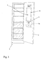
- Figure 1 shows a view in perspective of a household refrigerator featuring a cooled-drink dispenser in accordance with the teachings of the present invention;
- Figure 2 shows, schematically, the cooled-drink dispenser integrated in the Figure 1 refrigerator;
- Figure 3 shows, schematically, a variation of the cooled-drink dispenser shown schematically in Figure 2;
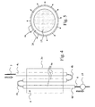
- Figure 4 shows, schematically, an alternative embodiment of the cooled-drink dispenser of the present invention; and
- Figure 5 illustrates part of the dispenser of Figure 4 in a working condition.
- With reference to Figures 1 and 2,
number 2 indicates as a whole a household appliance, preferably a refrigerator, having integrated therein a cooled-drink dispenser 1, so as to be suitable to supply cooled water or other beverage. - The cooled-
drink dispenser 1 is preferably integrated inside adoor 3 of theappliance 2. - The cooled-
drink dispenser 1 comprises atank 4 for temporarily storing water or any other beverage to be dispensed. In particular, thetank 4 is designed so that it can be completely filled by the water or other beverage, although during operations it can be also partially refilled. - The
dispenser 1 also comprises ametering valve 5 which, in the example shown, is located at a drink dispensingrecess 3a formed in the outer surface ofdoor 3 ofrefrigerator 2. Thevalve 5 is connected totank 4 by a connectingpipe 6, and is designed to only permit controlled outflow of water or any other beverage fromtank 4 to recess 3a whenrecess 3a is engaged by a glass or other container to receive the water. - The
tank 4 is completely housed, in the example shown in Figs. 2, inside acooling compartment 3b formed in thedoor 3 aboverecess 3a; alternatively, as shown in the embodiment of Figure 4 described later, thetank 4 may have parts extending outside thecompartment 3b. The cooled-drink dispenser 1 also comprises a second connectingpipe 7 permanently connectingtank 4 to asource 8 of pressurized water or other beverage so thattank 4 is always completely filled with water and does not contain air. Thedispenser 1 further comprises acooling assembly 9 which, on command, cools the liquid insidetank 4, and an electroniccentral control unit 10 which controlscooling assembly 9 on the basis of signals from a temperature sensor (not shown) for determining the temperature of the liquid insidetank 4, so as to bring the water or other beverage insidetank 4 to, and maintain it at, a reference temperature below or equal to the freezing temperature To (i.e. 0°C) of water or other beverage. - More specifically,
source 8 supplies water or any other beverage continuously at above atmospheric pressure, and the cooled-drink dispenser 1 preferably, though not necessarily, also comprises an on-offvalve 11 located along connectingpipe 7, upstream fromtank 4, and which, on command, isolatestank 4 fromsource 8 to cut off flow of water or other beverage. - In the example shown,
source 8 is defined by the drinking water circuit of the building in whichrefrigerator 2 is located. -
Tank 4 is advantageously defined by a variable-capacity container 4, which is preferably airtight. - In the example shown,
tank 4 is defined by a tubular body made of elastically deformable material, for instance silicone. The tubular body may be closed hermetically at both ends by two caps of rigid material to form a variable-volume closed container. The two caps are connected to the two connectingpipes source 8 to meteringvalve 5 via the whole oftank 4. Alternatively, the two ends may be properly extruded so as to fit with the two connecting pipes, and/or they can be fastened to the connecting pipes by means of hose clamps. - In an alternative embodiment,
tank 4 may be defined by a hermetically closed rigid container of constant internal volume and housing a closed capsule or container made of elastically deformable material and filled with gas. - The length, the internal diameter and the wall thickness of the
tank 4 may vary depending on the design and specifications of the dispenser, such as the amount and the temperature of the liquid to be dispensed. In the schematic illustrations of Figure 2, the tank is a relatively short and large cylinder, while in the illustration of Figure 4 it is an elongated tubular body. For example, thetank 4 can be a silicone tube of 1 m length and 18 mm internal diameter. - In the example shown,
cooling assembly 9 comprises a number of electric fans which, on command, circulate, insidecompartment 3b, a stream of cold air at a temperature below temperature T0 and/or a stream of hot air at a temperature above temperature T0. The electroniccentral control unit 10 is able to control the fans to alternate and/or mix the two air streams to bring the liquid insidetank 4 to, and maintain it at, around freezing temperature T0. The stream of cold air may come from the freezer compartment ofrefrigerator 2 storing frozen food requiring a temperature of -25°C to -20°C, and the stream of hot air may come from the fresh-food compartment ofrefrigerator 2 storing fresh food requiring a temperature of 2°C to 8°C. - The fans may be replaced by a conventional heatpump refrigeration circuit in which the evaporator is housed inside
compartment 3b, close totank 4, or by other refrigeration means. - With reference to Figure 2, the cooled-
drink dispenser 1 may also comprise asensor 12 for determining and communicating to the electroniccentral control unit 10 the amount of solid-state water or other beverage contained at all times insidetank 4. Moreover, depending on the design of thetank 4, the dispenser may also comprise means for preventing the formation of a single block of frozen liquid occupying the whole volume oftank 4 so as to obtain a biphasic (liquid state plus solid state) frozen liquid mixture, and preferably for assisting irregular, non-homogeneous crystallization of the liquid insidetank 4, so as to obtain a semisolid, high-viscosity, frozen liquid mixture. - More specifically, the cooled-
drink dispenser 1 may comprise a freezingprocess control device 13 designed to force the liquid freezing insidetank 4 to crystallize irregularly and non-homogeneously into a semisolid, high-viscosity mixture or slurry. - In the example shown in Figure 2, the freezing
process control device 13 is defined by an ultrasonic-frequency vibration emitter positioned close totank 4, and which, under the control of electroniccentral control unit 10, breaks up the ice or crystallized beverage formed intank 4 to obtain said semisolid, high-viscosity mixture of frozen water or other beverage. - As an alternative to vibration emitter, the formation of a block of ice or frozen beverage inside
tank 4 may also be prevented by cyclically and locally heating areas oftank 4 under the control of electroniccentral control unit 10, e.g. by means of a number of appropriately controlled resistors arranged inside the tank, to prevent the ice or frozen beverage crystals from adhering permanently to and forming layers on the walls of the tank. - In an alternative embodiment,
tank 4 may also be designed and/or cooled to restrict the formation of ice or frozen beverage crystals to certain predetermined points on the wall of the tank. In which case, freezingprocess control device 13 may be defined by an electrically operated propeller or stirring body housed insidetank 4 to keep the liquid inside the tank moving and detach the ice or frozen beverage crystals from the wall as they are formed. - In the embodiment illustrated in Figure 4, the
dispenser 1 can be realized without any freezing process control device, since the tubular body defining thetank 4 is so designed that, even if ice is formed therein so as to obstruct the passage when no liquid is supplied, it can radially expand when there is a sufficient pressure of liquid at its entrance, so as to allow liquid flow. As shown in Figure 5, thedispenser 1 of Figure 4 is therefore designed so as to allow passage of aliquid 20 between the ice formed insidetank 4, indicated with 19, and the internal wall oftank 4. The radial arrows indicate the outwardly expansion of thetank 5 when liquid (water or other beverage) is supplied at a pressure higher than atmospheric pressure. - To achieve the required liquid pressure, the
dispenser 1 may also include apump 18 alongpipe 6. Alternatively, a pump could be included alongpipe 7. - As shown in the embodiment of Figure 4, the
dispenser 1 may be designed so that someportions 4a of thetank 4, but their ending parts, are internal thecompartment 3b, while others, indicated with 4b, are external. Theinternal portions 4a are preferably straight and parallel with each other, while theexternal portions 4b, defining interconnection portions, are preferably bent. Theexternal portions 4b and the endings parts ofportions 4a are substantially at environmental temperature, so that ice formation is prevented in these parts. - Alternatively, the
tank 4 could be a uniform elongated tube properly bent inside thecompartment 3b, but the bending radius should be such as to allow the tube expansion when ice is completely formed inside. In fact, the Applicant has observed that, if ice obstructs the passage in a bent portion of the tank, the tank could be unable to expand in that portion to allow liquid flow if the bent is sharp. - Advantageously, also the initial and the final portions of the
tank 4, indicated with 4c and 4d respectively, are external thecompartment 3b, so that ice formation is prevented also in these zones, to facilitate liquid flow when thevalves 5 and/or 11 are opened. - Operation of the cooled-
drink dispenser 1 will now be described, assuming on-offvalve 11 is fully open to connecttank 4 directly tosource 8 and to filltank 4 completely with water fromsource 8. The temperature of the water supplied bysource 8 is obviously greater than the temperature of water or other beverage coming out of cooled-drink dispenser 1. - In actual use, electronic
central control unit 10controls cooling assembly 9 to bring the liquid insidetank 4 rapidly to below the freezing temperature To of water and so freeze the liquid. If the dispenser comprises also a freezing process control device 13 (i.e. the means for preventing the formation of a block of frozen liquid inside tank 4), thecontrol unit 10 also controlsdevice 13 to force the water or other beverage freezing insidetank 4 to crystallize irregularly and non-homogeneously into a biphasic or semisolid, high-viscosity, frozen drink mixture or slurry. - By means of
sensor 12, electroniccentral control unit 10 continuously controls the percentage of water that has passed from the liquid state to the solid or semisolid frozen water mixture state insidetank 4, and controlscooling assembly 9 so that the percentage of water in the solid or semisolid mixture state does not exceed a predetermined maximum threshold ranging between 50% and 90% of the maximum capacity oftank 4, so as to ensure free circulation of the water at all times insidetank 4. As previously explained, this control may be absent in the embodiment of Figure 4. - The cooled-
drink dispenser 1 is ready to dispense cooled water as soon as a sufficient amount of solid or semisolid frozen water mixture is produced insidetank 4. - Insertion of a glass inside
recess 3a indoor 3 opensmetering valve 5 to allow the water intank 4 to flow along connectingpipe 6 into the glass. -
Tank 4 being connected directly to pressurized-water source 8, the outflow of cooled water fromtank 4 along connectingpipe 6 is accompanied by a simultaneous inflow intotank 4 of an equal amount of water at ambient temperature fromsource 8. Insidetank 4, the water at ambient temperature fromsource 8 mixes with and partly melts the solid or semisolid frozen water mixture to form cooled water at a temperature of 8°C to 15°C (i.e. at a temperature below ambient temperature), which flows immediately along connectingpipe 6 into the glass. - In the embodiment of Figure 4, if the
tank 4 is obstructed by ice, the wall of thetank 4 expand outwardly due to the pressure of the incoming liquid, so as to allow passage of liquid between the ice block and the wall itself. - By appropriately regulating ambient-temperature water flow into tank 4 (which can be done by electronic
central control unit 10 appropriately controlling on-off valve 11) and the amount of solid or semisolid frozen water mixture insidetank 4, cooled water at a temperature of 8°C to 15°C can be obtained insidetank 4 for immediate supply along connectingpipe 6 into the glass. - Cooled-
drink dispenser 1 has numerous advantages. Above all, it provides for dispensing a quantity of cooled water, at a temperature ranging between 8°C and 15°C, much greater than the nominal capacity oftank 4, by using the solid or semisolid frozen water mixture as a thermal flywheel to rapidly cool the water fromsource 8. - The fact that
tank 4 is always filled completely with water at a temperature of substantially 0°C considerably reduces the growth-rate of mould and bacteria. - Clearly, changes may be made to the
household appliance 1 as described herein without, however, departing from the scope of the present invention. - For example, with reference to Figure 3, the cooled-
drink dispenser 1 may comprise, downstream fromtank 4, an electrically operatedhydraulic mixer 14 for mixing the cooled water flowing out oftank 4 along connectingpipe 6 with the ambient-temperature water fromsource 8. - More specifically,
hydraulic mixer 14 is a three-way mixer having a first inlet connected totank 4 by connectingpipe 6; a second inlet connected to connectingpipe 7, upstream fromtank 4 and downstream from on-offvalve 11, by abypass pipe 15; and one outlet connected tometering valve 5 by a connectingpipe 16. - In this variation, electronic
central control unit 10 controlshydraulic mixer 14 on the basis of signals from a temperature sensor for determining the temperature of the water supply tometering valve 5, so as to adjust the temperature of the water supplied tometering valve 5 by appropriately mixing the cooled water fromtank 4 with the ambient-temperature water directly fromsource 8. - In another embodiment the
household appliance 1 described above may have other uses. For example it can be used for cooling down the water in entrance to a traditional icemaker. In thatcase metering valve 5 is replaced by a traditional electrically controlled throttle valve or on-off valve located just before the icemaker so as to control the outflow of the water fromtank 4 to the icemaker.
Claims (18)
- An appliance (2) for the supplying of cooled water or other beverage, comprising an airtight tank (4) for temporarily storing the water or other beverage, a flow control device (5) for controlling the outflow of the water or other beverage from the tank (4), a cooling assembly (9) for cooling the water or other beverage inside said tank (4), and a control unit (10) for controlling said cooling assembly (9) to bring the water or other beverage inside the tank (4) to, and maintain it at, a predetermined reference temperature;
the appliance (2) being characterized in that said tank (4) is suitable to be completely filled by the water or other beverage and it communicates with a source (8) supplying said water or other beverage at a pressure higher than atmospheric pressure, and in that said control unit (10) is configured to control said cooling assembly (9) to bring the water or other beverage inside said tank (4) to, and maintain it at, a reference temperature below or equal to the freezing temperature (T0) of said water or other beverage, so as to freeze the water or other beverage. - An appliance as claimed in Claim 1, further comprising a freezing control device (13) operating on said tank to produce in said tank a liquid and solid state mixture.
- An appliance as claimed in claim 1 or 2, characterized in that said tank (4) is a closed, variable-capacity container (4).
- An appliance as claimed in any one of the foregoing claims, characterized in that said tank (4) comprises a tubular body made of an elastomeric material.
- An appliance as claimed in claim 4, characterized in that said tubular body is made of silicone.
- An appliance as claimed in any one of the foregoing claims, characterized in that it further comprises a cooling compartment (3b) housing at least part of said tank (4), said cooling assembly (9) being suitable to cool said compartment (3b).
- An appliance as claimed in claim 6, characterized in that said tank (4) comprises a plurality of longitudinal portions (4a) at least partially internal said compartment (3b), and at least one interconnection portion (4b) connecting two consecutive longitudinal portions (4a) and external said compartment (3b).
- An appliance as claimed in claim 7, characterized in that said tank (4) comprises also an initial portion (4c) and a final portion (4d) external said compartment (3b).
- An appliance as claimed in any one of the foregoing claims, characterized by also comprising an on-off valve (11) interposed between the tank (4) and said source (8); said on-off valve (11) being configured so as to isolate, on command, said tank (4) from said source (8) to cut off flow of the beverage.
- An appliance as claimed in any one of the foregoing claims, characterized by also comprising a hydraulic mixer (14) having two inlets connected respectively to said tank (4) and to said source (8), and one outlet connected to said flow control device (5); said hydraulic mixer (14) being configured to mix, on command, the cooled water or other beverage from the tank (4) with the ambient-temperature water or other beverage from said source (8), and to feed the resulting mixture to said flow control device (5) for controlling the outflow of the water or other beverage.
- An appliance as claimed in claim 2, characterized in that said freezing control device (13) comprise a frequency vibration emitter (13) positioned close to the tank (4), and suitable to break up the frozen water or beverage clusters formed inside the tank (4) to obtain said semisolid frozen drink mixture.
- An appliance as claimed in claim 2, characterized in that said freezing control device (13) comprises means for keeping the water or other beverage inside the tank (4) moving at all times.
- An appliance as claimed in any one of the foregoing claims, characterized in that said source (8) is defined by the drinking water circuit of the building in which the household appliance (2) is located.
- An appliance as claimed in any one of the foregoing claims, characterized in that the flow control device (5) comprises a metering valve (5) connected to the tank (4) and designed to permit controlled outflow of the water or other beverage from the tank (4) into a container positioned temporarily at the metering valve (5).
- An appliance as claimed in any one of the foregoing claims, characterized in that it comprises a door (3), and in that said tank (4), said flow control device (5) and said cooling assembly (9) are located on said door (3).
- A method for the supplying of cooled water or other beverage, characterized by comprising the steps of:- temporarily storing water or other beverage in an airtight tank (4) suitable to be completely filled by the water or other beverage;- cooling the water or other beverage inside said tank at a reference temperature below or equal to the freezing temperature (T0) of said water or other beverage, for freezing the water or other beverage;- supplying further water or other beverage from a source of water or other beverage to said tank at a pressure higher than atmospheric pressure; and- controlling the outflow of the water or other beverage from the tank.
- Method as claimed in claim 16, comprising the further steps of:- controlling the freezing process of said water or other beverage in said tank (4) so as to obtain a liquid and solid state mixture;- mixing said liquid and solid state mixture with water or other beverage at a higher temperature to obtain a liquid-state cooled water or other beverage; and- dispensing said liquid-state cooled water or other beverage.
- Operating method as claimed in claim 16 or 17, wherein the tank (4) comprises an elastic tube suitable to house said frozen water or other beverage and to expand radially when supplied with said further water or other beverage at a pressure higher than atmospheric pressure.
Priority Applications (1)
| Application Number | Priority Date | Filing Date | Title |
|---|---|---|---|
| EP07114478A EP1906120A1 (en) | 2006-09-29 | 2007-08-16 | Household appliance for the supplying of cooled water or other beverage and relative operation method |
Applications Claiming Priority (2)
| Application Number | Priority Date | Filing Date | Title |
|---|---|---|---|
| EP06121582A EP1906119A1 (en) | 2006-09-29 | 2006-09-29 | Household appliance for the supplying of cooled water or other beverage and relative operation method |
| EP07114478A EP1906120A1 (en) | 2006-09-29 | 2007-08-16 | Household appliance for the supplying of cooled water or other beverage and relative operation method |
Publications (1)
| Publication Number | Publication Date |
|---|---|
| EP1906120A1 true EP1906120A1 (en) | 2008-04-02 |
Family
ID=39126385
Family Applications (1)
| Application Number | Title | Priority Date | Filing Date |
|---|---|---|---|
| EP07114478A Withdrawn EP1906120A1 (en) | 2006-09-29 | 2007-08-16 | Household appliance for the supplying of cooled water or other beverage and relative operation method |
Country Status (1)
| Country | Link |
|---|---|
| EP (1) | EP1906120A1 (en) |
Cited By (4)
| Publication number | Priority date | Publication date | Assignee | Title |
|---|---|---|---|---|
| US9038401B2 (en) | 2008-09-26 | 2015-05-26 | Electrolux Home Products Corporation N.V. | Beverage cooler, a refrigerator comprising such a beverage cooler and a method for cooling beverage |
| CN112826326A (en) * | 2021-03-19 | 2021-05-25 | 广东斯柯电器有限公司 | Cold and hot drink device capable of quickly changing can |
| EP4083542A4 (en) * | 2019-12-27 | 2023-01-25 | Daikin Industries, Ltd. | ICE SUPPLY DEVICE AND ICE MAKING SYSTEM |
| CN115747515A (en) * | 2022-11-25 | 2023-03-07 | 宁波锦越新材料有限公司 | A high-purity aluminum continuous purification equipment |
Citations (6)
| Publication number | Priority date | Publication date | Assignee | Title |
|---|---|---|---|---|
| US2644318A (en) * | 1950-01-06 | 1953-07-07 | Gen Electric | Water cooler for refrigerator |
| US3908394A (en) * | 1974-11-14 | 1975-09-30 | Gen Electric | Water-dispensing system |
| US5315845A (en) * | 1991-04-17 | 1994-05-31 | Samsung Electronics Co., Ltd. | Cooling water storage tank of a refrigerator |
| GB2329460A (en) * | 1997-09-23 | 1999-03-24 | Lg Electronics Inc | Refrigerator dispenser assembly |
| WO2004102088A1 (en) * | 2003-05-16 | 2004-11-25 | Elizabeth Acton | Method and apparatus of freezing large volumes |
| JP2006176132A (en) * | 2004-12-20 | 2006-07-06 | Expert Wave Kk | Water feeder and method for manufacturing supercooled equivalent water |
-
2007
- 2007-08-16 EP EP07114478A patent/EP1906120A1/en not_active Withdrawn
Patent Citations (6)
| Publication number | Priority date | Publication date | Assignee | Title |
|---|---|---|---|---|
| US2644318A (en) * | 1950-01-06 | 1953-07-07 | Gen Electric | Water cooler for refrigerator |
| US3908394A (en) * | 1974-11-14 | 1975-09-30 | Gen Electric | Water-dispensing system |
| US5315845A (en) * | 1991-04-17 | 1994-05-31 | Samsung Electronics Co., Ltd. | Cooling water storage tank of a refrigerator |
| GB2329460A (en) * | 1997-09-23 | 1999-03-24 | Lg Electronics Inc | Refrigerator dispenser assembly |
| WO2004102088A1 (en) * | 2003-05-16 | 2004-11-25 | Elizabeth Acton | Method and apparatus of freezing large volumes |
| JP2006176132A (en) * | 2004-12-20 | 2006-07-06 | Expert Wave Kk | Water feeder and method for manufacturing supercooled equivalent water |
Cited By (5)
| Publication number | Priority date | Publication date | Assignee | Title |
|---|---|---|---|---|
| US9038401B2 (en) | 2008-09-26 | 2015-05-26 | Electrolux Home Products Corporation N.V. | Beverage cooler, a refrigerator comprising such a beverage cooler and a method for cooling beverage |
| EP4083542A4 (en) * | 2019-12-27 | 2023-01-25 | Daikin Industries, Ltd. | ICE SUPPLY DEVICE AND ICE MAKING SYSTEM |
| CN112826326A (en) * | 2021-03-19 | 2021-05-25 | 广东斯柯电器有限公司 | Cold and hot drink device capable of quickly changing can |
| CN115747515A (en) * | 2022-11-25 | 2023-03-07 | 宁波锦越新材料有限公司 | A high-purity aluminum continuous purification equipment |
| CN115747515B (en) * | 2022-11-25 | 2023-07-14 | 宁波锦越新材料有限公司 | A high-purity aluminum continuous purification equipment |
Similar Documents
| Publication | Publication Date | Title |
|---|---|---|
| CN113924267B (en) | Water distribution station | |
| US9062902B2 (en) | Defrost control for multiple barrel frozen product dispensers | |
| CN102405386B (en) | Refrigerator and control method thereof | |
| US8443621B2 (en) | Ice maker and method for making ice | |
| US5653114A (en) | Method and system for electronically controlling the location of the formation of ice within a closed loop water circulating unit | |
| RU2493509C2 (en) | Rack-mounted column, pouring device and temperature control method of drink | |
| EP1974802A1 (en) | Cool drink dispenser for home use, and refrigerator equipped with such a dispenser | |
| KR100772214B1 (en) | Transparent ice manufacturing apparatus and method | |
| WO2010034330A1 (en) | A beverage cooler, a refrigerator comprising such a beverage cooler and a method for cooling beverage | |
| US20110120163A1 (en) | Semi-Frozen Product Dispenser | |
| JP3852609B2 (en) | Ice making equipment, refrigerator | |
| WO2008037383A1 (en) | Household appliance for the supplying of cooled water or other beverage and relative operation method | |
| JP4396767B2 (en) | Freezer refrigerator | |
| KR20150128111A (en) | Apparatus and controlling method for making transparent ice | |
| US11703264B2 (en) | Ice making system for a refrigerator appliance | |
| KR20050117830A (en) | Apparatus for supplying water to refrigerator | |
| US3465537A (en) | Icemaker using condenser cooling water as thawing medium | |
| JP2002174483A (en) | Refrigeration system | |
| JP4159523B2 (en) | Frozen confectionery manufacturing equipment | |
| JP4197012B2 (en) | Freezer refrigerator | |
| EP2093529A1 (en) | Household appliance for the controlled supplying of cooled water or other beverage, and relative operating method | |
| JP4159490B2 (en) | Frozen confectionery manufacturing equipment | |
| JP2002243330A (en) | Refrigerator with automatic ice making device and control method thereof | |
| JP2003231593A (en) | Ice-storage-type beverage dispenser | |
| JP4169729B2 (en) | Frozen confectionery manufacturing equipment |
Legal Events
| Date | Code | Title | Description |
|---|---|---|---|
| PUAI | Public reference made under article 153(3) epc to a published international application that has entered the european phase |
Free format text: ORIGINAL CODE: 0009012 |
|
| AK | Designated contracting states |
Kind code of ref document: A1 Designated state(s): AT BE BG CH CY CZ DE DK EE ES FI FR GB GR HU IE IS IT LI LT LU LV MC MT NL PL PT RO SE SI SK TR |
|
| AX | Request for extension of the european patent |
Extension state: AL BA HR MK YU |
|
| 17P | Request for examination filed |
Effective date: 20081001 |
|
| 17Q | First examination report despatched |
Effective date: 20081104 |
|
| AKX | Designation fees paid |
Designated state(s): DE FR GB IT |
|
| STAA | Information on the status of an ep patent application or granted ep patent |
Free format text: STATUS: THE APPLICATION IS DEEMED TO BE WITHDRAWN |
|
| 18D | Application deemed to be withdrawn |
Effective date: 20090515 |