EP1906113A1 - Production method of evaporator - Google Patents
Production method of evaporator Download PDFInfo
- Publication number
- EP1906113A1 EP1906113A1 EP07117536A EP07117536A EP1906113A1 EP 1906113 A1 EP1906113 A1 EP 1906113A1 EP 07117536 A EP07117536 A EP 07117536A EP 07117536 A EP07117536 A EP 07117536A EP 1906113 A1 EP1906113 A1 EP 1906113A1
- Authority
- EP
- European Patent Office
- Prior art keywords
- tube
- metal
- metal tube
- heat conductivity
- high heat
- Prior art date
- Legal status (The legal status is an assumption and is not a legal conclusion. Google has not performed a legal analysis and makes no representation as to the accuracy of the status listed.)
- Granted
Links
- 238000004519 manufacturing process Methods 0.000 title claims abstract description 10
- 229910052751 metal Inorganic materials 0.000 claims abstract description 65
- 239000002184 metal Substances 0.000 claims abstract description 65
- 238000003466 welding Methods 0.000 claims abstract description 53
- 238000000034 method Methods 0.000 claims abstract description 26
- 239000012809 cooling fluid Substances 0.000 claims description 5
- 238000001816 cooling Methods 0.000 description 3
- 230000001154 acute effect Effects 0.000 description 2
- 239000012530 fluid Substances 0.000 description 2
- RYGMFSIKBFXOCR-UHFFFAOYSA-N Copper Chemical compound [Cu] RYGMFSIKBFXOCR-UHFFFAOYSA-N 0.000 description 1
- 239000000956 alloy Substances 0.000 description 1
- 229910045601 alloy Inorganic materials 0.000 description 1
- 239000004411 aluminium Substances 0.000 description 1
- 229910052782 aluminium Inorganic materials 0.000 description 1
- XAGFODPZIPBFFR-UHFFFAOYSA-N aluminium Chemical compound [Al] XAGFODPZIPBFFR-UHFFFAOYSA-N 0.000 description 1
- 230000005540 biological transmission Effects 0.000 description 1
- 238000005219 brazing Methods 0.000 description 1
- 239000011248 coating agent Substances 0.000 description 1
- 238000000576 coating method Methods 0.000 description 1
- 238000010276 construction Methods 0.000 description 1
- 229910052802 copper Inorganic materials 0.000 description 1
- 239000010949 copper Substances 0.000 description 1
- 230000003247 decreasing effect Effects 0.000 description 1
- 238000009826 distribution Methods 0.000 description 1
- 229920001971 elastomer Polymers 0.000 description 1
- 238000005265 energy consumption Methods 0.000 description 1
- 239000000463 material Substances 0.000 description 1
- 239000000155 melt Substances 0.000 description 1
- 150000002739 metals Chemical class 0.000 description 1
- 238000003825 pressing Methods 0.000 description 1
- 239000005060 rubber Substances 0.000 description 1
Images


Classifications
-
- F—MECHANICAL ENGINEERING; LIGHTING; HEATING; WEAPONS; BLASTING
- F28—HEAT EXCHANGE IN GENERAL
- F28F—DETAILS OF HEAT-EXCHANGE AND HEAT-TRANSFER APPARATUS, OF GENERAL APPLICATION
- F28F1/00—Tubular elements; Assemblies of tubular elements
- F28F1/10—Tubular elements and assemblies thereof with means for increasing heat-transfer area, e.g. with fins, with projections, with recesses
- F28F1/12—Tubular elements and assemblies thereof with means for increasing heat-transfer area, e.g. with fins, with projections, with recesses the means being only outside the tubular element
- F28F1/14—Tubular elements and assemblies thereof with means for increasing heat-transfer area, e.g. with fins, with projections, with recesses the means being only outside the tubular element and extending longitudinally
- F28F1/22—Tubular elements and assemblies thereof with means for increasing heat-transfer area, e.g. with fins, with projections, with recesses the means being only outside the tubular element and extending longitudinally the means having portions engaging further tubular elements
-
- B—PERFORMING OPERATIONS; TRANSPORTING
- B23—MACHINE TOOLS; METAL-WORKING NOT OTHERWISE PROVIDED FOR
- B23K—SOLDERING OR UNSOLDERING; WELDING; CLADDING OR PLATING BY SOLDERING OR WELDING; CUTTING BY APPLYING HEAT LOCALLY, e.g. FLAME CUTTING; WORKING BY LASER BEAM
- B23K20/00—Non-electric welding by applying impact or other pressure, with or without the application of heat, e.g. cladding or plating
- B23K20/10—Non-electric welding by applying impact or other pressure, with or without the application of heat, e.g. cladding or plating making use of vibrations, e.g. ultrasonic welding
-
- F—MECHANICAL ENGINEERING; LIGHTING; HEATING; WEAPONS; BLASTING
- F25—REFRIGERATION OR COOLING; COMBINED HEATING AND REFRIGERATION SYSTEMS; HEAT PUMP SYSTEMS; MANUFACTURE OR STORAGE OF ICE; LIQUEFACTION SOLIDIFICATION OF GASES
- F25B—REFRIGERATION MACHINES, PLANTS OR SYSTEMS; COMBINED HEATING AND REFRIGERATION SYSTEMS; HEAT PUMP SYSTEMS
- F25B39/00—Evaporators; Condensers
- F25B39/02—Evaporators
-
- F—MECHANICAL ENGINEERING; LIGHTING; HEATING; WEAPONS; BLASTING
- F28—HEAT EXCHANGE IN GENERAL
- F28D—HEAT-EXCHANGE APPARATUS, NOT PROVIDED FOR IN ANOTHER SUBCLASS, IN WHICH THE HEAT-EXCHANGE MEDIA DO NOT COME INTO DIRECT CONTACT
- F28D1/00—Heat-exchange apparatus having stationary conduit assemblies for one heat-exchange medium only, the media being in contact with different sides of the conduit wall, in which the other heat-exchange medium is a large body of fluid, e.g. domestic or motor car radiators
- F28D1/02—Heat-exchange apparatus having stationary conduit assemblies for one heat-exchange medium only, the media being in contact with different sides of the conduit wall, in which the other heat-exchange medium is a large body of fluid, e.g. domestic or motor car radiators with heat-exchange conduits immersed in the body of fluid
- F28D1/04—Heat-exchange apparatus having stationary conduit assemblies for one heat-exchange medium only, the media being in contact with different sides of the conduit wall, in which the other heat-exchange medium is a large body of fluid, e.g. domestic or motor car radiators with heat-exchange conduits immersed in the body of fluid with tubular conduits
- F28D1/047—Heat-exchange apparatus having stationary conduit assemblies for one heat-exchange medium only, the media being in contact with different sides of the conduit wall, in which the other heat-exchange medium is a large body of fluid, e.g. domestic or motor car radiators with heat-exchange conduits immersed in the body of fluid with tubular conduits the conduits being bent, e.g. in a serpentine or zig-zag
- F28D1/0477—Heat-exchange apparatus having stationary conduit assemblies for one heat-exchange medium only, the media being in contact with different sides of the conduit wall, in which the other heat-exchange medium is a large body of fluid, e.g. domestic or motor car radiators with heat-exchange conduits immersed in the body of fluid with tubular conduits the conduits being bent, e.g. in a serpentine or zig-zag the conduits being bent in a serpentine or zig-zag
-
- B—PERFORMING OPERATIONS; TRANSPORTING
- B23—MACHINE TOOLS; METAL-WORKING NOT OTHERWISE PROVIDED FOR
- B23K—SOLDERING OR UNSOLDERING; WELDING; CLADDING OR PLATING BY SOLDERING OR WELDING; CUTTING BY APPLYING HEAT LOCALLY, e.g. FLAME CUTTING; WORKING BY LASER BEAM
- B23K2101/00—Articles made by soldering, welding or cutting
- B23K2101/04—Tubular or hollow articles
- B23K2101/14—Heat exchangers
-
- F—MECHANICAL ENGINEERING; LIGHTING; HEATING; WEAPONS; BLASTING
- F25—REFRIGERATION OR COOLING; COMBINED HEATING AND REFRIGERATION SYSTEMS; HEAT PUMP SYSTEMS; MANUFACTURE OR STORAGE OF ICE; LIQUEFACTION SOLIDIFICATION OF GASES
- F25B—REFRIGERATION MACHINES, PLANTS OR SYSTEMS; COMBINED HEATING AND REFRIGERATION SYSTEMS; HEAT PUMP SYSTEMS
- F25B2339/00—Details of evaporators; Details of condensers
- F25B2339/02—Details of evaporators
- F25B2339/023—Evaporators consisting of one or several sheets on one face of which is fixed a refrigerant carrying coil
-
- F—MECHANICAL ENGINEERING; LIGHTING; HEATING; WEAPONS; BLASTING
- F28—HEAT EXCHANGE IN GENERAL
- F28F—DETAILS OF HEAT-EXCHANGE AND HEAT-TRANSFER APPARATUS, OF GENERAL APPLICATION
- F28F2275/00—Fastening; Joining
- F28F2275/06—Fastening; Joining by welding
- F28F2275/065—Fastening; Joining by welding by ultrasonic or vibration welding
Definitions
- This invention is related to the method of assembling the tube and plate which are contained in the plate tube type evaporators utilized in cooling devices by using ultrasonic welding.
- the evaporators used in the inventive method are plate tube type evaporators and basically comprise a metal tube (serpantine) with high heat conductivity and a metal plate with high heat conductivity.
- a metal tube with high heat conductivity through which a cooling fluid passes is secured onto a metal plate with high heat conductivity.
- thermal pastes, Al retainers and Al/PP/PVC bands with high heat conductivity are used in order to assemble a specific region of a metal tube to a metal plate.
- the contact between a metal tube and a metal plate cannot be provided at the desired level; therefore the heat transfer is also not performed at the desired level.
- the contact between the tube and the plate in the plate tube type evaporators is provided by using ultrasonic welding.
- the ultrasonic welding which is applied on the evaporator is maintained at a constant width and throughout the tube.
- a high contact between the metal plate and the metal tube is provided, obtaining a much smoother heat transfer surface area; since a more robust, regular and rigid structure is provided due to the quality of the ultrasonic welding seam, the evaporator operates with much higher thermal efficiency.
- An aim of this invention in the plate-tube type evaporators which are used in the cooling devices is to increase the thermal efficiency of the evaporators and thus to decrease the energy consumption of the coolers through the provision of a better contact and engagement between the tube and the plate surfaces by assembling the tube and the plate to each other with the ultrasonic welding method.
- Another aim of the invention is to provide a more homogenous temperature distribution over the evaporator by using the ultrasonic welding method.
- the ultrasonic welding method it is aimed to overcome the noise problem which arises in the tube due to movement of the fluid, contained in the tube, under a high pressure.
- Evaporator (A) Metal tube (1) Metal plate (2) Welding seam (3) Laser welding spot (4) Fixture (5) The application direction of the laser welding ray (6)
- the evaporator (A), of which front view is provided in fig. 1 and rear view is provided fig. 2, used in coolers of different type comprises a metal tube (1) with high heat conductivity in which a cooling fluid at low temperature circulates and a metal plate (2) with high heat conductivity on which the metal tube (1) is secured and which distributes the heat that the tube absorbs over the large surfaces evenly.
- the ultrasonic welding seam (3) which is used to assemble said two parts by the ultrasonic welding and applied perpendicularly to the circular section of the metal tube with high heat conductivity is shown in fig. 3.
- the metal plate (2) with high heat conductivity and the metal tube (1) with high heat conductivity are secured to each other throughout the tube (1) with a continuous seam by the tip of the welding machine of which seam width and seam shape (motif) can be changed.
- the ultrasonic welding which is applied on the evaporator (A) is maintained at a constant width and throughout the tube; therefore a better contact between the metal plate (2) and the metal tube (1) is provided, obtaining a smooth heat transfer surface area.
- a much more rigid, robust and smooth structure is obtained by the quality of the welding seam and the evaporator (A) operates with higher thermal efficiency.
- the current, pressure, frequency and circle parameters of the ultrasonic welding machine should be set according to the different thickness and alloy properties of the metals applied.
- the laser welding is used to assemble the metal tube and the metal plate which are contained in the evaporator.
- the seam is applied throughout the tube at certain intervals and in parallel with the circular section of the tube.
- the contact surface which provides the heat transfer is also increased, thus allowing evaporator to operate with high thermal efficiency.
- a metal plate (2) with high heat conductivity and the metal tube with high heat conductivity (1) are secured on each other at certain intervals as shown in fig. 5 or throughout the tube (1) with the continuous seam as shown in fig. 6, by changing the diameters of welding spots (4) and the intervals among them.
- the laser welding is applied from the direction behind the surface where the metal plate (2) meets the metal tube (1).
- securing the metal tube (1) on the metal plate (2) is performed quite easily through the advantage of the application direction of the laser welding ray (6) as shown in fig. 7.
- the fixture (5) used enables the laser ray to aim at the welding spot in the most accurate and reliable way.
Landscapes
- Engineering & Computer Science (AREA)
- Physics & Mathematics (AREA)
- Mechanical Engineering (AREA)
- Thermal Sciences (AREA)
- General Engineering & Computer Science (AREA)
- Geometry (AREA)
- Pressure Welding/Diffusion-Bonding (AREA)
- Organic Low-Molecular-Weight Compounds And Preparation Thereof (AREA)
- Heat-Exchange Devices With Radiators And Conduit Assemblies (AREA)
Abstract

Description
- This invention is related to the method of assembling the tube and plate which are contained in the plate tube type evaporators utilized in cooling devices by using ultrasonic welding.
- In the present cooling devices, mostly sheet-tube type evaporators, plate-tube type evaporators and roll-bond type evaporators are used. The evaporators used in the inventive method are plate tube type evaporators and basically comprise a metal tube (serpantine) with high heat conductivity and a metal plate with high heat conductivity.
- In the evaporators, a metal tube with high heat conductivity through which a cooling fluid passes is secured onto a metal plate with high heat conductivity. In these systems, thermal pastes, Al retainers and Al/PP/PVC bands with high heat conductivity are used in order to assemble a specific region of a metal tube to a metal plate. As a result of such assembling processes, the contact between a metal tube and a metal plate cannot be provided at the desired level; therefore the heat transfer is also not performed at the desired level.
- The section of a metal tube which is pressed after it is bent in a specific form is not constant throughout the tube. Therefore, the metal tubes which are placed on a planar metal plate do not exactly contact the plate surface at each point. Thermal pastes, Al retainers and bands which are used to provide this contact cannot apply a pressing force which will ensure the exact contact. As a result of the production processes, evaporators cannot have the total heat transfer surface area which is calculated at the design stage. As a result thereof, evaporator operates at a value which is below the thermal capacity calculated at the design stage. In order to provide this construction, the use of some parts which are not directly necessary for the mounting of the evaporator is also required.
- However, due to the high pressure flow of the fluid in the tube, an undesired noise problem arises in the metal tubes. In order to eliminate this problem, sound attenuating rubbers and Al retainers are used on the evaporator surface, but the problem cannot be strictly eliminated.
- In the systems disclosed in the patent documents
EP0222176 andW09835191 - In the patent document
JP 2001334333 - In the patent document
US006300591 , the method of assembling planar metal surface to a cylindrical surface by laser welding is described. In this method, in order to create a welding seam region, the planar surface is closed up to the cylindrical surface in such a way that the planar surface nearly touches it. Thus, the planar and cylindrical surfaces create an acute angle. The laser beam of rays formed later is transmitted to the welding seam region from this acute angle. One of the disadvantages of this method is that the angle of application of laser beam of rays must be bigger than the conical angle of the beam of rays in order for the focused welding beam of rays not to collide to the planar surface since welding process is performed from the side where the cylindrical surface exists. Another disadvantage is that it is difficult for the laser equipment to draw alongside a narrow area. - In the patent document
US20050145680 , the method of assembling copper tubes to one or more aluminium plates by using laser welding, with a similar method to the one disclosed in the patent documentUS006300591 is described. It is disclosed that in order to increase the efficiency, the tube can be welded from both sides simultaneously. This method also bears the abovementioned disadvantage disclosed in relation with the patent document UU006300591. - In the patent documents
W02006/065195 andW02006/067378 , the automation systems operate with a method similar to the ones disclosed in the patent documentsUS20050145680 andUS006300591 . - For the subject matter of the invention of ultrasonic welded evaporator production method, the contact between the tube and the plate in the plate tube type evaporators is provided by using ultrasonic welding. The ultrasonic welding which is applied on the evaporator is maintained at a constant width and throughout the tube. Thus, a high contact between the metal plate and the metal tube is provided, obtaining a much smoother heat transfer surface area; since a more robust, regular and rigid structure is provided due to the quality of the ultrasonic welding seam, the evaporator operates with much higher thermal efficiency.
- An aim of this invention in the plate-tube type evaporators which are used in the cooling devices is to increase the thermal efficiency of the evaporators and thus to decrease the energy consumption of the coolers through the provision of a better contact and engagement between the tube and the plate surfaces by assembling the tube and the plate to each other with the ultrasonic welding method.
- Another aim of the invention is to provide a more homogenous temperature distribution over the evaporator by using the ultrasonic welding method.
- In addition, by using the ultrasonic welding method, it is aimed to overcome the noise problem which arises in the tube due to movement of the fluid, contained in the tube, under a high pressure.
- The evaporator production method is shown in the attached drawings, wherein:
- Fig. 1 is a front view of the evaporator.
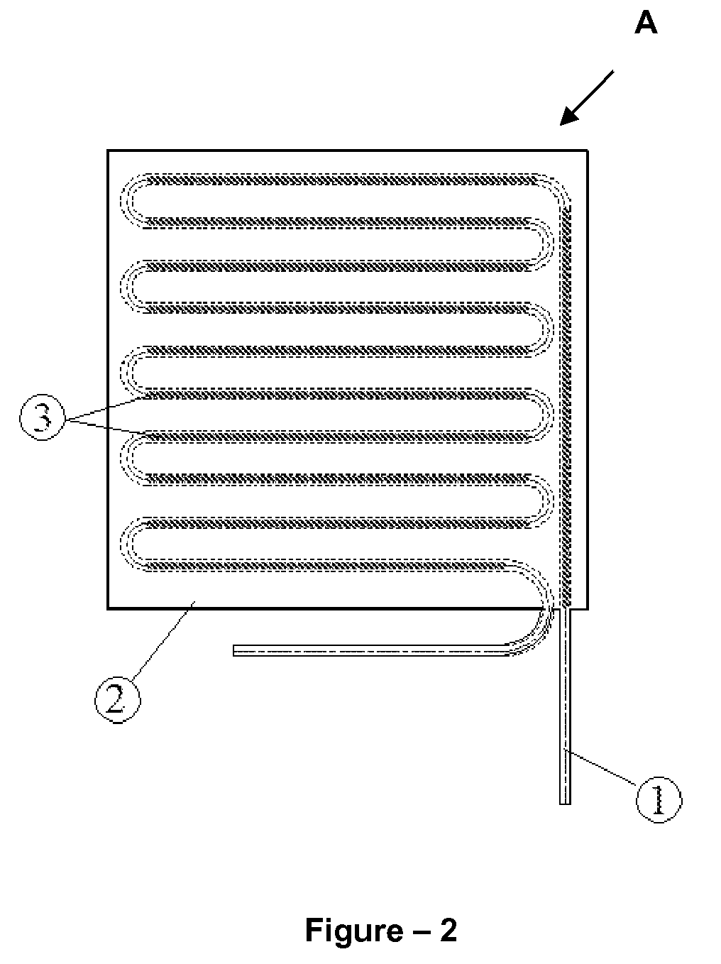
- Fig. 2 is a rear view of the evaporator.
- Fig. 3 is a view of the ultrasonic welding seam.
- Fig.4 is a view of the laser welding seam.
- Fig.5 is the detailed view of the intermittent laser welding seam application.
- Fig.6 is the detailed view of the continuous laser welding seam application.
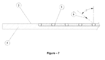
- Fig.7 is the view of the direction and shape of the laser welding application.
- The parts in the figures are numbered one by one and the corresponding terms of these numbers are given below.
Evaporator (A)
Metal tube (1)
Metal plate (2)
Welding seam (3)
Laser welding spot (4)
Fixture (5)
The application direction of the laser welding ray (6) - The evaporator (A), of which front view is provided in fig. 1 and rear view is provided fig. 2, used in coolers of different type comprises a metal tube (1) with high heat conductivity in which a cooling fluid at low temperature circulates and a metal plate (2) with high heat conductivity on which the metal tube (1) is secured and which distributes the heat that the tube absorbs over the large surfaces evenly. The ultrasonic welding seam (3) which is used to assemble said two parts by the ultrasonic welding and applied perpendicularly to the circular section of the metal tube with high heat conductivity is shown in fig. 3. With the ultrasonic welding method, the metal plate (2) with high heat conductivity and the metal tube (1) with high heat conductivity are secured to each other throughout the tube (1) with a continuous seam by the tip of the welding machine of which seam width and seam shape (motif) can be changed. The ultrasonic welding which is applied on the evaporator (A) is maintained at a constant width and throughout the tube; therefore a better contact between the metal plate (2) and the metal tube (1) is provided, obtaining a smooth heat transfer surface area. Thus a much more rigid, robust and smooth structure is obtained by the quality of the welding seam and the evaporator (A) operates with higher thermal efficiency.
- Since there are interferences at the size of sliding planes between the metal tube (1) and the metal plate (2) atoms on the region where the welding seam exists, in these regions the structure is continuous throughout the welding seam as if there is almost a single material. Thus, due to the low temperature of the cooling fluid which passes through the metal tube (1), the heat is absorbed from the surface of the metal plate (2) with the help of the regions where the ultrasonic welding seam (3) exists. In this way, the heat is absorbed from the inner volume of the cooler with which the metal plate (2) directly or indirectly contacts.
- In order to prevent the tearing problem which may occur in the welding seam and provide a continuous seam, the current, pressure, frequency and circle parameters of the ultrasonic welding machine should be set according to the different thickness and alloy properties of the metals applied.
- In assembling the metal tube (1) and the metal plate (2) with the ultrasonic welding, there is no need to use different elements such as thermal pastes, Al retainers and bands which are utilized in the prior art.
- In another embodiment of the invention, the laser welding is used to assemble the metal tube and the metal plate which are contained in the evaporator. In the laser welding, the seam is applied throughout the tube at certain intervals and in parallel with the circular section of the tube. In this assembling method, the contact surface which provides the heat transfer is also increased, thus allowing evaporator to operate with high thermal efficiency.
- In the method applied by using laser welding, a metal plate (2) with high heat conductivity and the metal tube with high heat conductivity (1) are secured on each other at certain intervals as shown in fig. 5 or throughout the tube (1) with the continuous seam as shown in fig. 6, by changing the diameters of welding spots (4) and the intervals among them. During this process, the laser welding is applied from the direction behind the surface where the metal plate (2) meets the metal tube (1). Thus, differently from other applications, securing the metal tube (1) on the metal plate (2) is performed quite easily through the advantage of the application direction of the laser welding ray (6) as shown in fig. 7. The fixture (5) used enables the laser ray to aim at the welding spot in the most accurate and reliable way. Angle and focusing problems and as a result of it, the difficulties in production experienced in the prior art can be eliminated through this method. In this application, as differently from the prior art, hot gas is passed through the metal tube (1) before, during and after the laser welding process, and thus the problems such as deformation and perforation appearing on metal tube (1) and the metal plate (2) during the laser welding process can be eliminated. Moreover, thanks to the hot gas application, the energy consumed by the laser ray during the laser welding process can also be decreased to some extent. Thus, a better contact between the metal plate (2) and the metal tube (1) is provided, obtaining a much smoother heat transfer surface area.
Claims (4)
- A production method of the evaporator (A) used in coolers of different type comprising a metal tube (1) with high heat conductivity in which a cooling fluid at low temperature circulates and a metal plate (2) with high heat conductivity on which the metal tube (1) is secured and which distributes the heat that the tube absorbs over the large surfaces evenly, characterized in that in order to obtain a smooth heat transfer surface area by providing a better contact between the metal plate (2) and the metal tube (1), the metal plate (2) with high heat conductivity and the metal tube (1) with high heat conductivity are secured to each other throughout the tube (1) with a continuous seam at a constant width using ultrasonic welding by the tip of the welding machine of which seam width and seam shape (3) can be changed.
- A production method of the evaporator (A) used in coolers of different type comprising a metal tube (1) with high heat conductivity in which a cooling fluid at low temperature circulates and a metal plate (2) with high heat conductivity on which the metal tube (1) is secured and which distributes the heat that the tube absorbs over the large surfaces evenly, characterized in that in order to obtain a smooth heat transfer surface area by providing a better contact between the metal plate (2) and the metal tube (1), the metal plate (2) with high heat conductivity and the metal tube (1) with high heat conductivity are secured to each other throughout the tube (1) with a continuous seam or at certain intervals changing the diameters of welding points (4) and the intervals between them by using laser welding.
- A production method according to claim 2 wherein the laser welding is applied from the direction behind the surface where the metal plate (2) meets the metal tube (1).
- A production method according to claim 2 wherein gas at high temperature is passed through the metal tube (1) before, during and after the laser welding process.
Applications Claiming Priority (1)
| Application Number | Priority Date | Filing Date | Title |
|---|---|---|---|
| TR2006/05393A TR200605393A2 (en) | 2006-09-29 | 2006-09-29 | Evaporator production method. |
Publications (2)
| Publication Number | Publication Date |
|---|---|
| EP1906113A1 true EP1906113A1 (en) | 2008-04-02 |
| EP1906113B1 EP1906113B1 (en) | 2009-06-17 |
Family
ID=39027530
Family Applications (1)
| Application Number | Title | Priority Date | Filing Date |
|---|---|---|---|
| EP07117536A Not-in-force EP1906113B1 (en) | 2006-09-29 | 2007-09-28 | Production method of evaporator |
Country Status (5)
| Country | Link |
|---|---|
| EP (1) | EP1906113B1 (en) |
| AT (1) | ATE434157T1 (en) |
| DE (1) | DE602007001322D1 (en) |
| ES (1) | ES2326927T3 (en) |
| TR (1) | TR200605393A2 (en) |
Cited By (5)
| Publication number | Priority date | Publication date | Assignee | Title |
|---|---|---|---|---|
| ITMI20090277A1 (en) * | 2009-02-26 | 2010-08-27 | Enrico Baldi | PROCEDURE FOR THE REALIZATION OF EVAPORATORS FOR REFRIGERATORS WITH ALUMINUM SERPENTINE CONNECTED TO AN ALUMINUM LAMINA. |
| ITMI20090752A1 (en) * | 2009-04-30 | 2010-11-01 | Enrico Baldi | PROCEDURE FOR THE REALIZATION OF EVAPORATORS FOR REFRIGERATORS WITH ALUMINUM SERPENTINE CONNECTED TO AN ALUMINUM LAMINA |
| WO2010091779A3 (en) * | 2009-02-14 | 2010-12-09 | Gsi Helmholtzzentrum Für Schwerionenforschung Gmbh | Heat transfer conductor |
| EP2223768A3 (en) * | 2009-02-26 | 2011-03-02 | Marta Montecucco | Method for making refrigerator evaporating devices including an aluminium coil arrangement coupled to an aluminium blade element |
| WO2014079128A1 (en) * | 2012-11-20 | 2014-05-30 | 海尔集团公司 | Evaporator for refrigerator and refrigerator with same |
Families Citing this family (1)
| Publication number | Priority date | Publication date | Assignee | Title |
|---|---|---|---|---|
| DE102017218639A1 (en) * | 2017-10-18 | 2019-04-18 | BSH Hausgeräte GmbH | Heat exchanger and method for its production |
Citations (5)
| Publication number | Priority date | Publication date | Assignee | Title |
|---|---|---|---|---|
| EP0834714A2 (en) * | 1996-10-04 | 1998-04-08 | Franz Lackner | Radiator |
| US6300591B1 (en) * | 2000-03-23 | 2001-10-09 | Sandia Corporation | Method for laser welding a fin and a tube |
| EP1550834A1 (en) * | 2004-01-02 | 2005-07-06 | Constantine Travassaros | Radiant panel |
| WO2006065195A1 (en) * | 2004-12-13 | 2006-06-22 | Sunstrip Ab | A method for manufacturing a heat-exchanger and a system for performing the method |
| GB2421457A (en) * | 2004-12-22 | 2006-06-28 | T I Group Automotive Systems L | A heat exchanger |
-
2006
- 2006-09-29 TR TR2006/05393A patent/TR200605393A2/en unknown
-
2007
- 2007-09-28 EP EP07117536A patent/EP1906113B1/en not_active Not-in-force
- 2007-09-28 ES ES07117536T patent/ES2326927T3/en active Active
- 2007-09-28 DE DE602007001322T patent/DE602007001322D1/en active Active
- 2007-09-28 AT AT07117536T patent/ATE434157T1/en not_active IP Right Cessation
Patent Citations (5)
| Publication number | Priority date | Publication date | Assignee | Title |
|---|---|---|---|---|
| EP0834714A2 (en) * | 1996-10-04 | 1998-04-08 | Franz Lackner | Radiator |
| US6300591B1 (en) * | 2000-03-23 | 2001-10-09 | Sandia Corporation | Method for laser welding a fin and a tube |
| EP1550834A1 (en) * | 2004-01-02 | 2005-07-06 | Constantine Travassaros | Radiant panel |
| WO2006065195A1 (en) * | 2004-12-13 | 2006-06-22 | Sunstrip Ab | A method for manufacturing a heat-exchanger and a system for performing the method |
| GB2421457A (en) * | 2004-12-22 | 2006-06-28 | T I Group Automotive Systems L | A heat exchanger |
Cited By (5)
| Publication number | Priority date | Publication date | Assignee | Title |
|---|---|---|---|---|
| WO2010091779A3 (en) * | 2009-02-14 | 2010-12-09 | Gsi Helmholtzzentrum Für Schwerionenforschung Gmbh | Heat transfer conductor |
| ITMI20090277A1 (en) * | 2009-02-26 | 2010-08-27 | Enrico Baldi | PROCEDURE FOR THE REALIZATION OF EVAPORATORS FOR REFRIGERATORS WITH ALUMINUM SERPENTINE CONNECTED TO AN ALUMINUM LAMINA. |
| EP2223768A3 (en) * | 2009-02-26 | 2011-03-02 | Marta Montecucco | Method for making refrigerator evaporating devices including an aluminium coil arrangement coupled to an aluminium blade element |
| ITMI20090752A1 (en) * | 2009-04-30 | 2010-11-01 | Enrico Baldi | PROCEDURE FOR THE REALIZATION OF EVAPORATORS FOR REFRIGERATORS WITH ALUMINUM SERPENTINE CONNECTED TO AN ALUMINUM LAMINA |
| WO2014079128A1 (en) * | 2012-11-20 | 2014-05-30 | 海尔集团公司 | Evaporator for refrigerator and refrigerator with same |
Also Published As
| Publication number | Publication date |
|---|---|
| EP1906113B1 (en) | 2009-06-17 |
| ES2326927T3 (en) | 2009-10-21 |
| ATE434157T1 (en) | 2009-07-15 |
| DE602007001322D1 (en) | 2009-07-30 |
| TR200605393A2 (en) | 2008-04-21 |
Similar Documents
| Publication | Publication Date | Title |
|---|---|---|
| EP1906113B1 (en) | Production method of evaporator | |
| US11415381B2 (en) | Heat exchanger with aluminum tubes rolled into an aluminum tube support | |
| US11150030B2 (en) | Vapor chamber | |
| EP2929269B1 (en) | Heat exchanger and method of manufacturing the same | |
| TWI302820B (en) | Fluid-containing cooling plate for an electronic component | |
| US20090266105A1 (en) | heat exchanger | |
| US20140231057A1 (en) | Heat exchanger incorporating integral flow directors | |
| US20110247794A1 (en) | Flattened tubes for use in heat exchangers and other systems, and associated methods of manufacture and use | |
| US20090211095A1 (en) | Microgrooves as Wick Structures in Heat Pipes and Method for Fabricating the Same | |
| US20130269914A1 (en) | Heat Exchanger for Refrigeration Cycle and Manufacturing Method for Same | |
| US20040000396A1 (en) | Corrugated fin heat exchanger and method of manufacture | |
| EP1550834B1 (en) | Radiant panel | |
| CN103759472A (en) | Micro heat exchanger with throttling function | |
| CN104708293B (en) | Method for manufacturing heat exchanger | |
| CN116160078B (en) | Aluminum brazing high-efficiency heat dissipation cold plate embedded with stainless steel capillary network and production method | |
| CN105526820A (en) | Finned type micro-channel heat exchanger | |
| JP5257102B2 (en) | Heat exchanger and refrigeration air conditioner | |
| CN100518469C (en) | Near-isothermal heat pipe radiator and manufacturing method thereof | |
| CN101776413B (en) | Heat exchanger and manufacturing method thereof | |
| JP6455103B2 (en) | Heat exchanger | |
| JP3972878B2 (en) | Cooling plate and manufacturing method thereof | |
| JP2010112656A (en) | Joining method of heat pipe and heat transfer member | |
| KR102063168B1 (en) | Structure of eletrode tip for spot welding equipment | |
| EP4039402B1 (en) | A method of bonding a capillary tube and a suction pipe by means of a fiber laser welding head and corresponding apparatus | |
| JP2016023893A (en) | Heat exchanger |
Legal Events
| Date | Code | Title | Description |
|---|---|---|---|
| PUAI | Public reference made under article 153(3) epc to a published international application that has entered the european phase |
Free format text: ORIGINAL CODE: 0009012 |
|
| AK | Designated contracting states |
Kind code of ref document: A1 Designated state(s): AT BE BG CH CY CZ DE DK EE ES FI FR GB GR HU IE IS IT LI LT LU LV MC MT NL PL PT RO SE SI SK TR |
|
| AX | Request for extension of the european patent |
Extension state: AL BA HR MK YU |
|
| 17P | Request for examination filed |
Effective date: 20080926 |
|
| AKX | Designation fees paid |
Designated state(s): AT BE BG CH CY CZ DE DK EE ES FI FR GB GR HU IE IS IT LI LT LU LV MC MT NL PL PT RO SE SI SK TR |
|
| GRAP | Despatch of communication of intention to grant a patent |
Free format text: ORIGINAL CODE: EPIDOSNIGR1 |
|
| GRAS | Grant fee paid |
Free format text: ORIGINAL CODE: EPIDOSNIGR3 |
|
| GRAA | (expected) grant |
Free format text: ORIGINAL CODE: 0009210 |
|
| AK | Designated contracting states |
Kind code of ref document: B1 Designated state(s): AT BE BG CH CY CZ DE DK EE ES FI FR GB GR HU IE IS IT LI LT LU LV MC MT NL PL PT RO SE SI SK TR |
|
| REG | Reference to a national code |
Ref country code: GB Ref legal event code: FG4D |
|
| REG | Reference to a national code |
Ref country code: CH Ref legal event code: EP |
|
| REG | Reference to a national code |
Ref country code: IE Ref legal event code: FG4D |
|
| REF | Corresponds to: |
Ref document number: 602007001322 Country of ref document: DE Date of ref document: 20090730 Kind code of ref document: P |
|
| REG | Reference to a national code |
Ref country code: ES Ref legal event code: FG2A Ref document number: 2326927 Country of ref document: ES Kind code of ref document: T3 |
|
| PG25 | Lapsed in a contracting state [announced via postgrant information from national office to epo] |
Ref country code: FI Free format text: LAPSE BECAUSE OF FAILURE TO SUBMIT A TRANSLATION OF THE DESCRIPTION OR TO PAY THE FEE WITHIN THE PRESCRIBED TIME-LIMIT Effective date: 20090617 Ref country code: LT Free format text: LAPSE BECAUSE OF FAILURE TO SUBMIT A TRANSLATION OF THE DESCRIPTION OR TO PAY THE FEE WITHIN THE PRESCRIBED TIME-LIMIT Effective date: 20090617 Ref country code: AT Free format text: LAPSE BECAUSE OF FAILURE TO SUBMIT A TRANSLATION OF THE DESCRIPTION OR TO PAY THE FEE WITHIN THE PRESCRIBED TIME-LIMIT Effective date: 20090617 |
|
| PG25 | Lapsed in a contracting state [announced via postgrant information from national office to epo] |
Ref country code: LV Free format text: LAPSE BECAUSE OF FAILURE TO SUBMIT A TRANSLATION OF THE DESCRIPTION OR TO PAY THE FEE WITHIN THE PRESCRIBED TIME-LIMIT Effective date: 20090617 Ref country code: PL Free format text: LAPSE BECAUSE OF FAILURE TO SUBMIT A TRANSLATION OF THE DESCRIPTION OR TO PAY THE FEE WITHIN THE PRESCRIBED TIME-LIMIT Effective date: 20090617 Ref country code: SI Free format text: LAPSE BECAUSE OF FAILURE TO SUBMIT A TRANSLATION OF THE DESCRIPTION OR TO PAY THE FEE WITHIN THE PRESCRIBED TIME-LIMIT Effective date: 20090617 Ref country code: SE Free format text: LAPSE BECAUSE OF FAILURE TO SUBMIT A TRANSLATION OF THE DESCRIPTION OR TO PAY THE FEE WITHIN THE PRESCRIBED TIME-LIMIT Effective date: 20090917 |
|
| PG25 | Lapsed in a contracting state [announced via postgrant information from national office to epo] |
Ref country code: EE Free format text: LAPSE BECAUSE OF FAILURE TO SUBMIT A TRANSLATION OF THE DESCRIPTION OR TO PAY THE FEE WITHIN THE PRESCRIBED TIME-LIMIT Effective date: 20090617 Ref country code: IS Free format text: LAPSE BECAUSE OF FAILURE TO SUBMIT A TRANSLATION OF THE DESCRIPTION OR TO PAY THE FEE WITHIN THE PRESCRIBED TIME-LIMIT Effective date: 20091017 Ref country code: CZ Free format text: LAPSE BECAUSE OF FAILURE TO SUBMIT A TRANSLATION OF THE DESCRIPTION OR TO PAY THE FEE WITHIN THE PRESCRIBED TIME-LIMIT Effective date: 20090617 Ref country code: RO Free format text: LAPSE BECAUSE OF FAILURE TO SUBMIT A TRANSLATION OF THE DESCRIPTION OR TO PAY THE FEE WITHIN THE PRESCRIBED TIME-LIMIT Effective date: 20090617 |
|
| PG25 | Lapsed in a contracting state [announced via postgrant information from national office to epo] |
Ref country code: SK Free format text: LAPSE BECAUSE OF FAILURE TO SUBMIT A TRANSLATION OF THE DESCRIPTION OR TO PAY THE FEE WITHIN THE PRESCRIBED TIME-LIMIT Effective date: 20090617 |
|
| PG25 | Lapsed in a contracting state [announced via postgrant information from national office to epo] |
Ref country code: PT Free format text: LAPSE BECAUSE OF FAILURE TO SUBMIT A TRANSLATION OF THE DESCRIPTION OR TO PAY THE FEE WITHIN THE PRESCRIBED TIME-LIMIT Effective date: 20091017 Ref country code: BG Free format text: LAPSE BECAUSE OF FAILURE TO SUBMIT A TRANSLATION OF THE DESCRIPTION OR TO PAY THE FEE WITHIN THE PRESCRIBED TIME-LIMIT Effective date: 20090917 |
|
| PLBE | No opposition filed within time limit |
Free format text: ORIGINAL CODE: 0009261 |
|
| STAA | Information on the status of an ep patent application or granted ep patent |
Free format text: STATUS: NO OPPOSITION FILED WITHIN TIME LIMIT |
|
| PG25 | Lapsed in a contracting state [announced via postgrant information from national office to epo] |
Ref country code: MC Free format text: LAPSE BECAUSE OF NON-PAYMENT OF DUE FEES Effective date: 20090930 Ref country code: DK Free format text: LAPSE BECAUSE OF FAILURE TO SUBMIT A TRANSLATION OF THE DESCRIPTION OR TO PAY THE FEE WITHIN THE PRESCRIBED TIME-LIMIT Effective date: 20090617 |
|
| 26N | No opposition filed |
Effective date: 20100318 |
|
| PG25 | Lapsed in a contracting state [announced via postgrant information from national office to epo] |
Ref country code: IE Free format text: LAPSE BECAUSE OF NON-PAYMENT OF DUE FEES Effective date: 20090928 |
|
| PG25 | Lapsed in a contracting state [announced via postgrant information from national office to epo] |
Ref country code: GR Free format text: LAPSE BECAUSE OF FAILURE TO SUBMIT A TRANSLATION OF THE DESCRIPTION OR TO PAY THE FEE WITHIN THE PRESCRIBED TIME-LIMIT Effective date: 20090918 |
|
| PG25 | Lapsed in a contracting state [announced via postgrant information from national office to epo] |
Ref country code: MT Free format text: LAPSE BECAUSE OF FAILURE TO SUBMIT A TRANSLATION OF THE DESCRIPTION OR TO PAY THE FEE WITHIN THE PRESCRIBED TIME-LIMIT Effective date: 20090617 Ref country code: LU Free format text: LAPSE BECAUSE OF NON-PAYMENT OF DUE FEES Effective date: 20090928 |
|
| PG25 | Lapsed in a contracting state [announced via postgrant information from national office to epo] |
Ref country code: HU Free format text: LAPSE BECAUSE OF FAILURE TO SUBMIT A TRANSLATION OF THE DESCRIPTION OR TO PAY THE FEE WITHIN THE PRESCRIBED TIME-LIMIT Effective date: 20091218 |
|
| PG25 | Lapsed in a contracting state [announced via postgrant information from national office to epo] |
Ref country code: CY Free format text: LAPSE BECAUSE OF FAILURE TO SUBMIT A TRANSLATION OF THE DESCRIPTION OR TO PAY THE FEE WITHIN THE PRESCRIBED TIME-LIMIT Effective date: 20090617 |
|
| PGFP | Annual fee paid to national office [announced via postgrant information from national office to epo] |
Ref country code: FR Payment date: 20110726 Year of fee payment: 5 |
|
| PGFP | Annual fee paid to national office [announced via postgrant information from national office to epo] |
Ref country code: ES Payment date: 20110822 Year of fee payment: 5 Ref country code: TR Payment date: 20110909 Year of fee payment: 5 Ref country code: GB Payment date: 20110701 Year of fee payment: 5 |
|
| PGFP | Annual fee paid to national office [announced via postgrant information from national office to epo] |
Ref country code: IT Payment date: 20100930 Year of fee payment: 4 |
|
| PGFP | Annual fee paid to national office [announced via postgrant information from national office to epo] |
Ref country code: BE Payment date: 20110929 Year of fee payment: 5 Ref country code: NL Payment date: 20111003 Year of fee payment: 5 |
|
| REG | Reference to a national code |
Ref country code: CH Ref legal event code: PL |
|
| PGFP | Annual fee paid to national office [announced via postgrant information from national office to epo] |
Ref country code: DE Payment date: 20111128 Year of fee payment: 5 |
|
| PG25 | Lapsed in a contracting state [announced via postgrant information from national office to epo] |
Ref country code: CH Free format text: LAPSE BECAUSE OF NON-PAYMENT OF DUE FEES Effective date: 20110930 Ref country code: LI Free format text: LAPSE BECAUSE OF NON-PAYMENT OF DUE FEES Effective date: 20110930 |
|
| BERE | Be: lapsed |
Owner name: VESTEL BEYAZ ESYA SANAYI VE TICARET A.S. Effective date: 20120930 |
|
| REG | Reference to a national code |
Ref country code: NL Ref legal event code: V1 Effective date: 20130401 |
|
| GBPC | Gb: european patent ceased through non-payment of renewal fee |
Effective date: 20120928 |
|
| REG | Reference to a national code |
Ref country code: FR Ref legal event code: ST Effective date: 20130531 |
|
| PG25 | Lapsed in a contracting state [announced via postgrant information from national office to epo] |
Ref country code: GB Free format text: LAPSE BECAUSE OF NON-PAYMENT OF DUE FEES Effective date: 20120928 Ref country code: BE Free format text: LAPSE BECAUSE OF NON-PAYMENT OF DUE FEES Effective date: 20120930 Ref country code: DE Free format text: LAPSE BECAUSE OF NON-PAYMENT OF DUE FEES Effective date: 20130403 |
|
| PG25 | Lapsed in a contracting state [announced via postgrant information from national office to epo] |
Ref country code: NL Free format text: LAPSE BECAUSE OF NON-PAYMENT OF DUE FEES Effective date: 20130401 Ref country code: FR Free format text: LAPSE BECAUSE OF NON-PAYMENT OF DUE FEES Effective date: 20121001 Ref country code: IT Free format text: LAPSE BECAUSE OF NON-PAYMENT OF DUE FEES Effective date: 20120928 |
|
| REG | Reference to a national code |
Ref country code: DE Ref legal event code: R119 Ref document number: 602007001322 Country of ref document: DE Effective date: 20130403 |
|
| REG | Reference to a national code |
Ref country code: ES Ref legal event code: FD2A Effective date: 20131018 |
|
| PG25 | Lapsed in a contracting state [announced via postgrant information from national office to epo] |
Ref country code: ES Free format text: LAPSE BECAUSE OF NON-PAYMENT OF DUE FEES Effective date: 20120929 |
|
| PG25 | Lapsed in a contracting state [announced via postgrant information from national office to epo] |
Ref country code: TR Free format text: LAPSE BECAUSE OF NON-PAYMENT OF DUE FEES Effective date: 20120928 |