EP1906108A2 - Hydrogen heating - Google Patents
Hydrogen heating Download PDFInfo
- Publication number
- EP1906108A2 EP1906108A2 EP07113899A EP07113899A EP1906108A2 EP 1906108 A2 EP1906108 A2 EP 1906108A2 EP 07113899 A EP07113899 A EP 07113899A EP 07113899 A EP07113899 A EP 07113899A EP 1906108 A2 EP1906108 A2 EP 1906108A2
- Authority
- EP
- European Patent Office
- Prior art keywords
- hydrogen
- burner
- gas
- heating
- heater
- Prior art date
- Legal status (The legal status is an assumption and is not a legal conclusion. Google has not performed a legal analysis and makes no representation as to the accuracy of the status listed.)
- Withdrawn
Links
Images

Classifications
-
- F—MECHANICAL ENGINEERING; LIGHTING; HEATING; WEAPONS; BLASTING
- F24—HEATING; RANGES; VENTILATING
- F24H—FLUID HEATERS, e.g. WATER OR AIR HEATERS, HAVING HEAT-GENERATING MEANS, e.g. HEAT PUMPS, IN GENERAL
- F24H1/00—Water heaters, e.g. boilers, continuous-flow heaters or water-storage heaters
- F24H1/0027—Water heaters, e.g. boilers, continuous-flow heaters or water-storage heaters using fluid fuel
-
- B—PERFORMING OPERATIONS; TRANSPORTING
- B60—VEHICLES IN GENERAL
- B60H—ARRANGEMENTS OF HEATING, COOLING, VENTILATING OR OTHER AIR-TREATING DEVICES SPECIALLY ADAPTED FOR PASSENGER OR GOODS SPACES OF VEHICLES
- B60H1/00—Heating, cooling or ventilating [HVAC] devices
- B60H1/00271—HVAC devices specially adapted for particular vehicle parts or components and being connected to the vehicle HVAC unit
-
- B—PERFORMING OPERATIONS; TRANSPORTING
- B60—VEHICLES IN GENERAL
- B60H—ARRANGEMENTS OF HEATING, COOLING, VENTILATING OR OTHER AIR-TREATING DEVICES SPECIALLY ADAPTED FOR PASSENGER OR GOODS SPACES OF VEHICLES
- B60H1/00—Heating, cooling or ventilating [HVAC] devices
- B60H1/22—Heating, cooling or ventilating [HVAC] devices the heat being derived otherwise than from the propulsion plant
- B60H1/2203—Heating, cooling or ventilating [HVAC] devices the heat being derived otherwise than from the propulsion plant the heat being derived from burners
-
- F—MECHANICAL ENGINEERING; LIGHTING; HEATING; WEAPONS; BLASTING
- F24—HEATING; RANGES; VENTILATING
- F24D—DOMESTIC- OR SPACE-HEATING SYSTEMS, e.g. CENTRAL HEATING SYSTEMS; DOMESTIC HOT-WATER SUPPLY SYSTEMS; ELEMENTS OR COMPONENTS THEREFOR
- F24D18/00—Small-scale combined heat and power [CHP] generation systems specially adapted for domestic heating, space heating or domestic hot-water supply
-
- F—MECHANICAL ENGINEERING; LIGHTING; HEATING; WEAPONS; BLASTING
- F24—HEATING; RANGES; VENTILATING
- F24H—FLUID HEATERS, e.g. WATER OR AIR HEATERS, HAVING HEAT-GENERATING MEANS, e.g. HEAT PUMPS, IN GENERAL
- F24H3/00—Air heaters
- F24H3/02—Air heaters with forced circulation
- F24H3/06—Air heaters with forced circulation the air being kept separate from the heating medium, e.g. using forced circulation of air over radiators
-
- B—PERFORMING OPERATIONS; TRANSPORTING
- B60—VEHICLES IN GENERAL
- B60H—ARRANGEMENTS OF HEATING, COOLING, VENTILATING OR OTHER AIR-TREATING DEVICES SPECIALLY ADAPTED FOR PASSENGER OR GOODS SPACES OF VEHICLES
- B60H1/00—Heating, cooling or ventilating [HVAC] devices
- B60H1/22—Heating, cooling or ventilating [HVAC] devices the heat being derived otherwise than from the propulsion plant
- B60H2001/2268—Constructional features
- B60H2001/2284—Fuel supply
-
- F—MECHANICAL ENGINEERING; LIGHTING; HEATING; WEAPONS; BLASTING
- F24—HEATING; RANGES; VENTILATING
- F24D—DOMESTIC- OR SPACE-HEATING SYSTEMS, e.g. CENTRAL HEATING SYSTEMS; DOMESTIC HOT-WATER SUPPLY SYSTEMS; ELEMENTS OR COMPONENTS THEREFOR
- F24D2101/00—Electric generators of small-scale CHP systems
- F24D2101/30—Fuel cells
-
- F—MECHANICAL ENGINEERING; LIGHTING; HEATING; WEAPONS; BLASTING
- F24—HEATING; RANGES; VENTILATING
- F24D—DOMESTIC- OR SPACE-HEATING SYSTEMS, e.g. CENTRAL HEATING SYSTEMS; DOMESTIC HOT-WATER SUPPLY SYSTEMS; ELEMENTS OR COMPONENTS THEREFOR
- F24D2103/00—Thermal aspects of small-scale CHP systems
- F24D2103/10—Small-scale CHP systems characterised by their heat recovery units
- F24D2103/13—Small-scale CHP systems characterised by their heat recovery units characterised by their heat exchangers
-
- F—MECHANICAL ENGINEERING; LIGHTING; HEATING; WEAPONS; BLASTING
- F24—HEATING; RANGES; VENTILATING
- F24D—DOMESTIC- OR SPACE-HEATING SYSTEMS, e.g. CENTRAL HEATING SYSTEMS; DOMESTIC HOT-WATER SUPPLY SYSTEMS; ELEMENTS OR COMPONENTS THEREFOR
- F24D2200/00—Heat sources or energy sources
- F24D2200/16—Waste heat
- F24D2200/19—Fuel cells
-
- F—MECHANICAL ENGINEERING; LIGHTING; HEATING; WEAPONS; BLASTING
- F24—HEATING; RANGES; VENTILATING
- F24D—DOMESTIC- OR SPACE-HEATING SYSTEMS, e.g. CENTRAL HEATING SYSTEMS; DOMESTIC HOT-WATER SUPPLY SYSTEMS; ELEMENTS OR COMPONENTS THEREFOR
- F24D2200/00—Heat sources or energy sources
- F24D2200/16—Waste heat
- F24D2200/26—Internal combustion engine
-
- F—MECHANICAL ENGINEERING; LIGHTING; HEATING; WEAPONS; BLASTING
- F24—HEATING; RANGES; VENTILATING
- F24H—FLUID HEATERS, e.g. WATER OR AIR HEATERS, HAVING HEAT-GENERATING MEANS, e.g. HEAT PUMPS, IN GENERAL
- F24H2240/00—Fluid heaters having electrical generators
- F24H2240/10—Fluid heaters having electrical generators with fuel cells
Definitions
- the present invention relates to a hydrogen heater, so a heater that can be operated with hydrogen as a fuel.
- the conversion of hydrogen that is, the conversion of the chemically bound in hydrogen energy into electrical energy and / or heat can be realized with extremely low pollutant emissions, whereby hydrogen as an energy source increasingly gaining in interest.
- the present invention is concerned with the problem of pointing out an advantageous way for the use of hydrogen as an energy carrier, which is characterized in particular by low pollutant emissions.
- the aim is exhaust gases that are virtually free of carbon dioxide, contain very little nitrogen oxides and are largely free of hydrocarbons.
- the present invention is based on the general idea of providing a hydrogen heater in which in a burner, hydrogen gas supplied from a hydrogen tank is burned with oxidizer gas supplied from an oxidizer supply means to thereby produce hot burner exhaust gases whose heat is dissipated a heat exchanger downstream of the burner is transferred to a heating medium.
- the heating medium can then be used in principle in any way to meet a heat demand.
- the conversion of pure hydrogen with pure oxygen is virtually pollutant-free, so that the pollutant emissions of the hydrogen heater mainly depend on the composition of the oxidizer gas used and can therefore be low.
- the oxidant gas used is ambient air which contains oxygen and nitrogen as main components. By controlling the combustion temperature in the burner, extremely low emission levels for nitrogen oxides can be achieved. Due to the combustion principle used, emissions of carbon monoxide, carbon dioxide and hydrocarbons virtually do not occur.
- the hydrogen heater according to the invention can be configured in one embodiment as a building heating, which serves to heat a building.
- said building is equipped with a heating circuit in which circulates the aforementioned heating medium. Accordingly, the heat exchanger of the hydrogen heater in the heating circuit of the building involved.
- This embodiment thus proposes the use of hydrogen heating as building heating.
- the hydrogen heater according to the invention may be designed as a parking heater or as a heater of a motor vehicle.
- This embodiment thus proposes the use of the hydrogen heater as a parking heater or as a heater in a motor vehicle.
- the motor vehicle equipped with the hydrogen heater has a hydrogen-powered drive device which is connected to a hydrogen tank arranged in the vehicle.
- the burner of the likewise arranged in the vehicle hydrogen heater is then also connected to the provided for supplying the drive means hydrogen tank of the vehicle.
- Vehicles with a hydrogen-powered drive device for example in the form of internal combustion engines or fuel cells, are known per se.
- the proposed integration of the hydrogen heater in such a vehicle can improve the lifetime of the drive device or the comfort of the vehicle.
- Efficient drive devices generate comparatively little waste heat, so that the drive device takes a relatively long time until it reaches its optimum operating temperature. Below its optimum operating temperature, the respective drive device, in particular an internal combustion engine, is exposed to increased wear; furthermore, it tends to increase pollutant emission levels.
- the respective drive means can be brought faster to its optimum operating temperature.
- a heating of a vehicle interior can only be carried out satisfactorily if the drive device generates sufficient excess heat. By the heater, the heat required for the heating of the vehicle interior can be efficiently provided. Due to the hydrogen-powered auxiliary heater, sufficient heat can be provided even when the drive device is switched off in order to directly heat the vehicle interior and / or to preheat the drive device.
- a hydrogen heater 1 comprises a hydrogen tank 2, a burner 3, an oxidant feed device 4 and a heat exchanger 5.
- the hydrogen tank 2 serves to store hydrogen.
- the hydrogen tank 2 may be configured as a pressure vessel in which the hydrogen is e.g. stored at 700 bar in compressed form.
- the hydrogen tank 2 can be designed as a thermally insulated container in which the hydrogen is stored in liquid form at about - 250 ° C. It is clear that in principle, a hydrogen tank is conceivable, which is designed as a thermally insulated pressure vessel for compressed and cooled, in particular liquid, hydrogen.
- the hydrogen tank 2 can be equipped with a device 6, with the aid of which evaporation of the hydrogen stored in the hydrogen tank 2 in liquid form can be realized. Additionally or alternatively, a cooling device may be provided in order to ensure the low temperatures for storing the liquid hydrogen.
- the burner 3 contains a combustion chamber 7 and has a first input 8 and a second input 9.
- the first Input 8 communicates with a first distribution path 10 while the second input 9 communicates with a second distribution path 11.
- the burner 3 is connected via the first input 8 to the hydrogen tank 2, and the Oxidatorzu slaughter 4 is connected to the second input 9.
- Hydrogen gas thus enters the first distributor path 10 while an oxidizer gas enters the second distributor path 11.
- the two distribution paths 10, 11 are expediently configured in such a way that the hydrogen gas and the oxidizing gas flow separately into the combustion chamber 7 from a wall structure 12 which delimits the combustion chamber 7 on the input side, in each case through a multiplicity of openings.
- the openings associated with the hydrogen gas and the openings associated with the oxidizer gas are expediently distributed regularly or uniformly within the wall structure 12.
- the Oxidatorzu slaughter slaughter 4 comprises an oxidizer 18, which is connected to the second input 9 and in which a conveyor 19 is arranged.
- the oxidizer gas 15 contains oxygen.
- air is used as the oxidizing gas 15.
- the oxidizer conduit 18 suitably includes a check valve 62 downstream of the conveyor, e.g. a non-return valve, as a backflow protection.
- the heat exchanger 5 is integrated on the one hand in the exhaust pipe 13 and on the other hand in a heating path 20.
- a heating medium circulates 21.
- the heat exchanger 5 is designed so that it transfers heat from the burner exhaust gas 16 to the heating medium 21 during operation of the hydrogen heater 1, without resulting in a fluid exchange.
- a conveyor 22 is also suitably arranged, e.g. a blower or a pump.
- the hydrogen line 17 contains, downstream of the hydrogen tank 2, for example, a check valve or overflow valve 23. Downstream of this valve 23, a pressure limiter 24 may be arranged in the hydrogen line 17. Furthermore, a metering unit 25 can optionally be arranged downstream of the pressure limiter 24 in the hydrogen line 17. The metering unit 25 is designed so that it can meter the burner 3 the amount of hydrogen required to achieve the required heating power.
- a controller 63 is provided which is connected via control lines, for example with the evaporation device, with the blocking / overflow valve 23, with the pressure limiter 24, with the metering unit and with the conveyor 18. Furthermore, the controller 63 can communicate with a sensor system 64 which has, for example, at least one temperature sensor 65, at least one flame sensor 66 and / or at least one lambda sensor 67.
- the embodiment of the hydrogen heater 1 shown in FIG. 1 can be configured, for example, as a building heater, with the aid of which a building, not shown here, can be heated.
- the building has e.g. a heating circuit 26.
- This heating circuit 26 is formed here by the heating path 20. Accordingly, the heating medium circulates in the heating circuit 26 21.
- the heat exchanger 5 is integrated into this heating circuit 26.
- the housing radiator and the like are involved in the heating circuit 26 in the usual way. In modern buildings with low-energy or self-sufficient construction, the heat exchanger 5 can be integrated into a supply air path 26 of the building in order to heat the supply air supplied to the building, which then forms the heating medium 21.
- the hydrogen heater 1 is designed as a parking heater or as a heater of a motor vehicle, not shown here.
- hydrogen heater 1 can additional Heat to be provided, in the event that a drive device 27 of the vehicle produces too little heat or must be heated itself.
- the hydrogen heater 1 can be used when heat is to be generated when the drive device 27 is turned off.
- the drive device 27 can be heated to a desired operating temperature.
- a vehicle interior 28 can be heated with the aid of the hydrogen heater 1.
- the vehicle has a drive device 27, which can be operated with hydrogen.
- a hydrogen tank is arranged, in which the hydrogen is stored for operating the drive device 27.
- the hydrogen heater 21 is arranged in accordance with preferred embodiments in such a motor vehicle, can be used as a hydrogen tank for supplying the burner 3 of the already existing in the vehicle hydrogen tank, so this is also referred to in the following with 2. Accordingly, the burner 3 is connected to the arranged in the vehicle hydrogen tank 2 of the vehicle.
- the drive device 27 has a fuel cell 29 and an electric motor 30.
- the fuel cell 29 serves to generate electric current from a hydrogen-containing anode gas and an oxygen-containing cathode gas.
- the hydrogen gas 14 is used, so that in the following also the anode gas is denoted by 14.
- Air is expediently used as the cathode gas, which air also serves as the oxidizing gas 15, so that the cathode gas is also referred to below as 15.
- the fuel cell 29 has an anode gas inlet 30, to which a branch of the hydrogen line 17 is connected.
- said branch branches off between the blocking / overflow valve 23 and the pressure limiter 24 from the section of the hydrogen line 17 connected to the hydrogen tank 2.
- a pressure limiter 24 and a metering unit 25 are expediently also arranged, the latter being designed such that it can measure or shut off the respectively required amount of hydrogen from the fuel cell 29 so that the fuel cell 29 can provide the respective required electrical energy.
- the fuel cell 29 has a cathode gas inlet 32, to which a cathode gas supply device 33 is connected. This comprises a cathode gas line 34, which is connected to the cathode gas inlet 32, and a conveyor 35, for example a pump or a blower.
- the fuel cell 29 includes an anode side 36 and a cathode side 37, which are separated from each other in particular by an electrolyte 38.
- hydrogen is converted or converted into electricity, so that electrical current 40 can be tapped on the fuel cell 29 at at least one electrical connection 39.
- the electric motor 30 is now electrically connected to the fuel cell 29, that is connected to the electrical connection 39.
- the fuel cell 29 may be configured, for example, as a high-temperature fuel cell, in particular as a solid fuel cell (so-called "SOFC” fuel cell).
- SOFC solid fuel cell
- the working temperature of such a high-temperature fuel cell is at a maximum of about 850 ° C.
- the fuel cell 29 may be designed as a low-temperature fuel cell.
- this is a fuel cell 29 which operates with a proton exchange membrane or with a polymer electrolyte membrane, so-called "PEM” fuel cell.
- the working temperature of such a low-temperature fuel cell is at a maximum at about 80 ° to 150 ° C.
- the hydrogen heater 1 can optionally be equipped with a feed device 68, with the aid of which steam can be introduced into the cathode gas 15.
- the feed device 68 is arranged, for example, upstream of the cathode gas inlet 32 in the cathode gas line 34.
- a removal device 69 can optionally be provided.
- the removal device 69 With the help of the removal device 69 46 steam can be withdrawn from the cathode exhaust gas.
- the removal device 69 is preferably arranged in a cathode exhaust gas line 70 which contains the cathode exhaust gas outlet 43 of the fuel cell 29 connects to the cathode exhaust gas inlet 47 of the burner 3.
- an operative connection 71 may exist, which is indicated here by a broken line.
- feed device 68 and the removal device 69 form a structural unit, so that the operative connection 71 is arranged in the interior of such a combined feed and removal device.
- the use of such a combined feed and removal device, for example, by a corresponding course of the cathode exhaust gas line 70 and / or the cathode gas line 34 can be realized.
- such a fuel cell 29 consists of a stack of individual fuel cell elements, wherein such a stack is limited on the output side by a closure plate 41.
- hydrogen-containing anode exhaust gas 44 passes to an anode exhaust gas inlet 45 of the burner 3.
- the anode exhaust gas inlet 45 communicates with the first distribution path 10, so that the first distribution path 10 has an anode exhaust gas input area of Burner 3 forms.
- the second distribution path 11 forms a cathode exhaust gas inlet region of the burner 3. It is noteworthy that the burner 3, regardless of the fuel cell 29 also to the Hydrogen tank 2 is connected, wherein the corresponding branch of the hydrogen pipe 17 is also connected via the first input 8 to the anode exhaust gas inlet region 10.
- the Oxidatorzu slaughter 4 is connected via the second input 9 to the cathode exhaust gas inlet region 11 of the burner 3.
- the oxidizer feed device 4 and the cathode gas feed device 33 if the same gas, in particular air, is used for the oxidizer gas and the cathode gas.
- the exhaust gases of the fuel cell 29 still contain hydrogen and oxygen due to the incomplete conversion therein and can be used in the burner 3 to generate heat. If the heat output of the burner 3, which can be achieved solely by the exhaust gases of the fuel cell 29, is insufficient, the burner 3 is metered directly with hydrogen gas 14 directly from the hydrogen tank 2 and oxidizer gas 15 directly via the oxidizer supply means 4.
- the heat exchanger 5 of the hydrogen heater 1 is shown in FIG. 2 Embodiment involved in a warm air duct 48 of the vehicle.
- Said hot air duct 48 is formed here by the heating path 20 and forms part of an interior heating of the vehicle.
- the heated from the burner exhaust gas 16 heating medium 21 forms in this case, the vehicle interior 28 supplied hot air.
- the hydrogen heater 1 can be used for direct heating of the vehicle interior 28.
- the hydrogen heater 1, for example be installed in a so-called climate module as a heater.
- climate modules or so-called HVAC systems, where "HVAC” stands for Heater, Ventilation and Air Condition are combined systems for heating, ventilating, cooling or generally for air conditioning of rooms, especially in motor vehicles.
- the burner 3 can be structurally integrated into the fuel cell 29, such that the burner 3 replaces said end plate 41 and the end plate 41 forms. This allows a particularly compact design can be achieved.
- the drive device 27 comprises a combustion engine 49 that can be operated with hydrogen and that is integrated into a cooling circuit 50.
- a cooling medium 51 circulates in the cooling circuit 50.
- the cooling circuit 50 contains a delivery device 52, for example a pump or a blower.
- a heat exchanger 53 can optionally be arranged which is usually referred to as a vehicle radiator and which is acted upon during operation of the vehicle with an air flow 54.
- the internal combustion engine 49 is connected to the hydrogen tank 2 via a corresponding branch of the hydrogen pipe 17. Said branch is derived from the connected to the hydrogen tank 2 portion of the hydrogen line 17 at between the check / overflow valve 23 and the pressure limiter 24 and preferably also includes a pressure limiter 24 and a further dosing unit 25. Suitably, this dosing unit 25 is located directly on the internal combustion engine 49th , eg in the form of an injection or injection device, which is assigned to the individual cylinders of the internal combustion engine 49.
- the internal combustion engine 49 is also connected to a fresh gas line 55 via which the internal combustion engine 49 receives an oxygen-containing fresh gas, expediently air.
- the fresh gas can correspond in its consistency to the oxidizer gas and will therefore also be referred to below as 15.
- the internal combustion engine 49 generates in operation by the combustion of hydrogen gas with fresh gas 15 engine exhaust 56, which is discharged via a corresponding exhaust pipe 57.
- the heat exchanger 5 of the hydrogen heater 1 directly for heating the vehicle interior 28.
- a corresponding heating path 20 and a corresponding hot air duct 48 are indicated in Fig. 3 by broken lines.
- the heating of the vehicle interior 28 by means of a hot air duct 58, which is coupled via a further heat exchanger 59 with the cooling circuit 50 of the engine 49 heat transfer.
- the heated cooling medium 51 heat can be introduced via said heat exchanger 59 in air transported in the hot air duct 48, so as to generate warm air, which can then be supplied to the vehicle interior 28.
- said hot air duct 48 also contains a suitable conveyor 60, in particular a pump or a fan.
- the heating of the vehicle interior 28 takes place with the aid of the heat in the cooling circuit 50.
- the heat exchanger 5 of the hydrogen heater 1 is now integrated into the cooling circuit 50 of the internal combustion engine 49.
- a control valve 61 controls the flow through the heat exchanger 5 with the cooling medium 51, which in this embodiment forms the heating medium of the heat exchanger 5, that is, the heating medium which can be heated with the aid of the hot burner exhaust gases 16.
- the heat exchanger 5 is preferably arranged parallel to the vehicle radiator 53 of the cooling circuit 50 and can form a bypass to the vehicle radiator 53 with appropriate control of the control valve 61.
- heat can be supplied to the cooling medium 51, if necessary, for example, to bring the internal combustion engine 49 as quickly as possible to its optimum operating temperature and / or the cooling circuit 50 via the heat exchanger 59 of the hot air duct 58 sufficient heat to heat the vehicle interior 28th to be able to withdraw.
- the hydrogen heater 1 is then used for indirect heating of the interior 28.
- the hydrogen heater 1 as a heating device in a climate module or in an HVAC system.
- the heat exchanger 5 can be structurally integrated into the burner 3, in such a way that the heat exchanger 5 limits the combustion chamber 7 on the output side.
- the hot burner exhaust gases 16 pass directly through the heat exchanger 5 from the burner 3.
- the burner 3 can also be used, inter alia, to burn excess hydrogen 14 in a controlled manner, in order to avoid polluting the environment. This is particularly advantageous when a hydrogen tank 2 is used, in which the hydrogen is provided in a liquid state at low temperatures. Despite best insulation measures, the liquid hydrogen always seeks to equalize the temperature with the environment, resulting in evaporation of a portion of the hydrogen, which leads to a pressure increase in the hydrogen tank 2.
- the overflow valve 23 and the burner 3 can be selectively actuated via the controller 63 so that when a predetermined maximum pressure is reached for a short time the burner 3 is operated to to dispose of this excess hydrogen gas.
- the heat generated in this relaxation process of the hydrogen tank 2 can be used, for example, for heating the drive device 27 and / or the vehicle interior 28.
Abstract
Description
Die vorliegende Erfindung betrifft eine Wasserstoffheizung, also eine Heizeinrichtung, die mit Wasserstoff als Brennstoff betrieben werden kann.The present invention relates to a hydrogen heater, so a heater that can be operated with hydrogen as a fuel.
Die Umsetzung von Wasserstoff, also die Umwandlung der im Wasserstoff chemisch gebundenen Energie in elektrische Energie und/oder in Wärme lässt sich mit extrem niedrigen Schadstoffemissionen realisieren, wodurch Wasserstoff als Energieträger zunehmend an Interesse gewinnt.The conversion of hydrogen, that is, the conversion of the chemically bound in hydrogen energy into electrical energy and / or heat can be realized with extremely low pollutant emissions, whereby hydrogen as an energy source increasingly gaining in interest.
Die vorliegende Erfindung beschäftigt sich mit dem Problem, für die Nutzung von Wasserstoff als Energieträger einen vorteilhaften Weg aufzuzeigen, der sich insbesondere durch niedrige Schadstoffemissionen auszeichnet. Angestrebt sind Abgase, die quasi frei von Kohlendioxid sind, sehr wenig Stickoxide enthalten und weitgehend frei von Kohlenwasserstoffen sind.The present invention is concerned with the problem of pointing out an advantageous way for the use of hydrogen as an energy carrier, which is characterized in particular by low pollutant emissions. The aim is exhaust gases that are virtually free of carbon dioxide, contain very little nitrogen oxides and are largely free of hydrocarbons.
Dieses Problem wird erfindungsgemäß durch den Gegenstand des unabhängigen Anspruchs gelöst. Vorteilhafte Ausführungsformen sind Gegenstand der abhängigen Ansprüche.This problem is solved according to the invention by the subject matter of the independent claim. Advantageous embodiments are the subject of the dependent claims.
Die vorliegende Erfindung beruht auf dem allgemeinen Gedanken, eine Wasserstoffheizung bereitzustellen, bei der in einem Brenner Wasserstoffgas, das von einem Wasserstofftank zugeführt wird, mit Oxidatorgas, das von einer Oxidatorzuführeinrichtung zugeführt wird, zu verbrennen, um dadurch heiße Brennerabgase zu erzeugen, deren Wärme in einem dem Brenner nachgeordneten Wärmeübertrager auf ein Heizmedium übertragen wird. Das Heizmedium kann dann grundsätzlich auf beliebige Weise genutzt werden, um einen Wärmebedarf zu decken. Die Umsetzung von reinem Wasserstoff mit reinem Sauerstoff ist quasi schadstofffrei, so dass die Schadstoffemissionen der Wasserstoffheizung hauptsächlich von der Zusammensetzung des verwendeten Oxidatorgases abhängen und dementsprechend niedrig sein können. Beispielsweise wird als Oxidatorgas Umgebungsluft verwendet, die als Hauptkomponenten Sauerstoff und Stickstoff enthält. Durch Beherrschen der Verbrennungstemperatur im Brenner lassen sich extrem niedrige Emissionswerte für Stickoxide erzielen. Durch das verwendete Verbrennungsprinzip treten Emissionen von Kohlenmonoxiden, Kohlendioxiden und Kohlenwasserstoffen quasi nicht auf.The present invention is based on the general idea of providing a hydrogen heater in which in a burner, hydrogen gas supplied from a hydrogen tank is burned with oxidizer gas supplied from an oxidizer supply means to thereby produce hot burner exhaust gases whose heat is dissipated a heat exchanger downstream of the burner is transferred to a heating medium. The heating medium can then be used in principle in any way to meet a heat demand. The conversion of pure hydrogen with pure oxygen is virtually pollutant-free, so that the pollutant emissions of the hydrogen heater mainly depend on the composition of the oxidizer gas used and can therefore be low. For example, the oxidant gas used is ambient air which contains oxygen and nitrogen as main components. By controlling the combustion temperature in the burner, extremely low emission levels for nitrogen oxides can be achieved. Due to the combustion principle used, emissions of carbon monoxide, carbon dioxide and hydrocarbons virtually do not occur.
Die erfindungsgemäße Wasserstoffheizung kann bei einer Ausführungsform als Gebäudeheizung ausgestaltet sein, die zum Beheizen eines Gebäudes dient. Hierzu ist besagtes Gebäude mit einem Heizkreis ausgestattet, in dem das zuvor genannte Heizmedium zirkuliert. Dementsprechend ist der Wärmeübertrager der Wasserstoffheizung in den Heizkreis des Gebäudes eingebunden. Diese Ausführungsform schlägt somit die Verwendung der Wasserstoffheizung als Gebäudeheizung vor.The hydrogen heater according to the invention can be configured in one embodiment as a building heating, which serves to heat a building. For this purpose, said building is equipped with a heating circuit in which circulates the aforementioned heating medium. Accordingly, the heat exchanger of the hydrogen heater in the heating circuit of the building involved. This embodiment thus proposes the use of hydrogen heating as building heating.
Bei einer anderen Ausführungsform kann die erfindungsgemäße Wasserstoffheizung als Standheizung oder als Zuheizer eines Kraftfahrzeugs ausgestaltet sein. Diese Ausführungsform schlägt somit die Verwendung der Wasserstoffheizung als Standheizung oder als Zuheizer in einem Kraftfahrzeug vor. Eine derartige Ausführungsform ist insbesondere dann von Vorteil, wenn das mit der Wasserstoffheizung ausgestattete Kraftfahrzeug eine mit Wasserstoff betriebene Antriebseinrichtung aufweist, die an einen im Fahrzeug angeordneten Wasserstofftank angeschlossen ist. Der Brenner der ebenfalls im Fahrzeug angeordneten Wasserstoffheizung ist dann ebenfalls an den zur Versorgung der Antriebseinrichtung vorgesehenen Wasserstofftank des Fahrzeugs angeschlossen. Fahrzeuge mit einer mit Wasserstoff betriebenen Antriebseinrichtung, z.B. in Form von Verbrennungsmotoren oder Brennstoffzellen, sind an sich bekannt. Durch die vorgeschlagene Integration der Wasserstoffheizung in ein derartiges Fahrzeug lässt sich die Lebenszeit der Antriebseinrichtung bzw. der Komfort des Fahrzeugs verbessern. Effiziente Antriebseinrichtungen erzeugen vergleichsweise wenig Abwärme, so dass die Antriebseinrichtung relativ lange braucht, bis sie ihre optimale Betriebstemperatur erreicht. Unterhalb ihrer optimalen Betriebstemperatur ist die jeweilige Antriebseinrichtung, insbesondere ein Verbrennungsmotor, erhöhtem Verschleiß ausgesetzt; des weiteren neigt sie zu erhöhten Schadstoffemissionswerten. Durch den ebenfalls mit Wasserstoff betriebenen Zuheizer kann die jeweilige Antriebseinrichtung rascher auf ihre optimale Betriebstemperatur gebracht werden. Desweiteren kann eine Beheizung eines Fahrzeuginnenraums nur dann zufriedenstellend durchgeführt werden, wenn die Antriebseinrichtung hinreichend überschüssige Wärme erzeugt. Durch den Zuheizer kann die für die Beheizung des Fahrzeuginnenraums benötigte Wärme effizient bereitgestellt werden. Durch die mit Wasserstoff betriebene Standheizung kann auch bei ausgeschalteter Antriebseinrichtung hinreichend Wärme bereitgestellt werden, um den Fahrzeuginnenraum direkt zu Beheizen und/oder um die Antriebseinrichtung vorzuwärmen.In another embodiment, the hydrogen heater according to the invention may be designed as a parking heater or as a heater of a motor vehicle. This embodiment thus proposes the use of the hydrogen heater as a parking heater or as a heater in a motor vehicle. Such an embodiment is particularly advantageous if the motor vehicle equipped with the hydrogen heater has a hydrogen-powered drive device which is connected to a hydrogen tank arranged in the vehicle. The burner of the likewise arranged in the vehicle hydrogen heater is then also connected to the provided for supplying the drive means hydrogen tank of the vehicle. Vehicles with a hydrogen-powered drive device, for example in the form of internal combustion engines or fuel cells, are known per se. The proposed integration of the hydrogen heater in such a vehicle can improve the lifetime of the drive device or the comfort of the vehicle. Efficient drive devices generate comparatively little waste heat, so that the drive device takes a relatively long time until it reaches its optimum operating temperature. Below its optimum operating temperature, the respective drive device, in particular an internal combustion engine, is exposed to increased wear; furthermore, it tends to increase pollutant emission levels. By also powered by hydrogen Heater, the respective drive means can be brought faster to its optimum operating temperature. Furthermore, a heating of a vehicle interior can only be carried out satisfactorily if the drive device generates sufficient excess heat. By the heater, the heat required for the heating of the vehicle interior can be efficiently provided. Due to the hydrogen-powered auxiliary heater, sufficient heat can be provided even when the drive device is switched off in order to directly heat the vehicle interior and / or to preheat the drive device.
Weitere wichtige Merkmale und Vorteile der Erfindung ergeben sich aus den Unteransprüchen, aus den Zeichnungen und aus der zugehörigen Figurenbeschreibung anhand der Zeichnungen.Other important features and advantages of the invention will become apparent from the dependent claims, from the drawings and from the associated figure description with reference to the drawings.
Es versteht sich, dass die vorstehend genannten und die nachstehend noch zu erläuternden Merkmale nicht nur in der jeweils angegebenen Kombination, sondern auch in anderen Kombinationen oder in Alleinstellung verwendbar sind, ohne den Rahmen der vorliegenden Erfindung zu verlassen.It is understood that the features mentioned above and those yet to be explained below can be used not only in the particular combination given, but also in other combinations or in isolation, without departing from the scope of the present invention.
Bevorzugte Ausführungsbeispiele der Erfindung sind in den Zeichnungen dargestellt und werden in der nachfolgenden Beschreibung näher erläutert, wobei sich gleiche Bezugszeichen auf gleiche oder ähnliche oder funktional gleiche Bauteile beziehen.Preferred embodiments of the invention are illustrated in the drawings and will be described in more detail in the following description, wherein like reference numerals refer to the same or similar or functionally identical components.
Es zeigen, jeweils schematisch,
- Fig. 1 bis 3
- jeweils eine stark vereinfachte, schaltplanartige Prinzipskizze einer Wasserstoffheizung bei unterschiedlichen Ausführungsformen.
- Fig. 1 to 3
- in each case a greatly simplified, circuit diagram-like schematic diagram of a hydrogen heater in different embodiments.
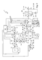
Entsprechend den Fig. 1 bis 3 umfasst eine erfindungsgemäße Wasserstoffheizung 1 einen Wasserstofftank 2, einen Brenner 3, eine Oxidatorzuführeinrichtung 4 und einen Wärmeübertrager 5. Der Wasserstofftank 2 dient zum Speichern von Wasserstoff. Dabei kann der Wasserstofftank 2 als Druckbehälter ausgestaltet sein, in dem der Wasserstoff z.B. bei 700 bar in komprimierter Form bevorratet wird. Alternativ kann der Wasserstofftank 2 als thermisch isolierter Behälter ausgestaltet sein, in dem der Wasserstoff in flüssiger Form bei ca. - 250°C bevorratet wird. Es ist klar, dass grundsätzlich auch ein Wasserstofftank denkbar ist, der als thermisch isolierter Druckbehälter für komprimierten und gekühlten, insbesondere flüssigen, Wasserstoff ausgestaltet ist.According to FIGS. 1 to 3, a hydrogen heater 1 according to the invention comprises a
Der Wasserstofftank 2 kann mit einer Einrichtung 6 ausgestattet sein, mit deren Hilfe eine Verdampfung des im Wasserstofftank 2 in flüssiger Form gespeicherten Wasserstoffs realisierbar ist. Zusätzlich oder alternativ kann auch eine Kühleinrichtung vorgesehen sein, um die niedrigen Temperaturen zur Bevorratung des flüssigen Wasserstoffs gewährleisten zu können.The
Der Brenner 3 enthält einen Brennraum 7 und weist einen ersten Eingang 8 sowie einen zweiten Eingang 9 auf. Der erste Eingang 8 kommuniziert mit einem ersten Verteilerpfad 10, während der zweite Eingang 9 mit einem zweiten Verteilerpfad 11 kommuniziert. Der Brenner 3 ist über den ersten Eingang 8 an den Wasserstofftank 2 angeschlossen, und die Oxidatorzuführeinrichtung 4 ist an den zweiten Eingang 9 angeschlossen. Wasserstoffgas gelangt somit in den ersten Verteilerpfad 10, während ein Oxidatorgas in den zweiten Verteilerpfad 11 gelangt. Die beiden Verteilerpfade 10, 11 sind zweckmäßig so ausgestaltet, dass aus einer Wandstruktur 12, die den Brennraum 7 eingangsseitig begrenzt, das Wasserstoffgas und das Oxidatorgas jeweils durch eine Vielzahl von Öffnungen separat in den Brennraum 7 einströmen. Hierzu sind die dem Wasserstoffgas zugeordneten Öffnungen und die dem Oxidatorgas zugeordneten Öffnungen zweckmäßig innerhalb der Wandstruktur 12 regelmäßig oder gleichmäßig verteilt angeordnet.The
Im Brennraum 7 findet im Betrieb des Brenners 3 eine Verbrennungsreaktion statt, bei welcher das Wasserstoffgas mit dem Oxidatorgas verbrennt, wobei heiße Brennerabgase generiert werden. Eine Abgasleitung 13 führt das Brennerabgas vom Brenner 3 weg. In den Fig. 1 bis 3 ist das Wasserstoffgas mit 14 bezeichnet, das Oxidatorgas ist mit 15 bezeichnet und das Brennerabgas ist mit 16 bezeichnet. Das Wasserstoffgas 14 wird dem Brenner 3 über eine Wasserstoffleitung 17 zugeführt, die den Wasserstofftank 2 mit dem ersten Eingang 8 verbindet.In the
Die Oxidatorzuführeinrichtung 4 umfasst eine Oxidatorleitung 18, die an den zweiten Eingang 9 angeschlossen ist und in der eine Fördereinrichtung 19 angeordnet ist. Die Fördereinrichtung 19, z.B. ein Gebläse, eine Pumpe, ein Kompressor oder eine Turbine, transportiert Oxidatorgas zum zweiten Eingang 9. Das Oxidatorgas 15 enthält Sauerstoff. Bevorzugt wird als Oxidatorgas 15 Luft verwendet. Die Oxidatorleitung 18 enthält zweckmäßig stromab der Fördereinrichtung ein Sperrventil 62, z.B. ein Rückschlagsperrventil, als Rückströmsicherung.The Oxidatorzuführeinrichtung 4 comprises an
Der Wärmeübertrager 5 ist einerseits in die Abgasleitung 13 und andererseits in einen Heizpfad 20 eingebunden. Im Heizpfad 20 zirkuliert ein Heizmedium 21. Der Wärmeübertrager 5 ist so ausgestaltet, dass er im Betrieb der Wasserstoffheizung 1 Wärme vom Brennerabgas 16 auf das Heizmedium 21 überträgt, ohne dass es dabei zu einem Fluidaustausch kommt. Im Heizpfad 20 ist zweckmäßig ebenfalls eine Fördereinrichtung 22 angeordnet, z.B. ein Gebläse oder eine Pumpe.The
Die Wasserstoffleitung 17 enthält stromab des Wasserstofftanks 2 beispielsweise ein Sperrventil oder Überströmventil 23. Stromab dieses Ventils 23 kann ein Druckbegrenzer 24 in der Wasserstoffleitung 17 angeordnet sein. Ferner kann optional in der Wasserstoffleitung 17 stromab des Druckbegrenzers 24 eine Dosiereinheit 25 angeordnet sein. Die Dosiereinheit 25 ist so ausgestaltet, dass sie dem Brenner 3 die für die Erzielung der jeweils benötigten Heizleistung erforderliche Wasserstoffmenge zumessen kann. Zum Betreiben der Wasserstoffheizung 1 ist zweckmäßig eine Steuerung 63 vorgesehen, die über Steuerleitungen z.B. mit der Verdampfungsvorrichtung, mit dem Sperr-/Überströmventil 23, mit dem Druckbegrenzer 24, mit der Dosiereinheit und mit der Fördereinrichtung 18 verbunden ist. Ferner kann die Steuerung 63 mit einer Sensorik 64 kommunizieren, die beispielsweise zumindest einen Temperatursensor 65, zumindest einen Flammensensor 66 und/oder zumindest einen Lambda-Sensor 67 aufweist.The
Die in Fig. 1 gezeigte Ausführungsform der Wasserstoffheizung 1 kann beispielsweise als Gebäudeheizung ausgestaltet sein, mit deren Hilfe ein hier nicht gezeigtes Gebäude beheizt werden kann. Das Gebäude weist z.B. einen Heizkreis 26 auf. Dieser Heizkreis 26 ist hier durch den Heizpfad 20 gebildet. Dementsprechend zirkuliert im Heizkreis 26 das Heizmedium 21. Desweiteren ist der Wärmeübertrager 5 in diesen Heizkreis 26 eingebunden. Innerhalb des Gehäuses sind in den Heizkreis 26 in üblicher Weise Heizkörper und dergleichen eingebunden. Bei modernen Gebäuden mit Niedrigenergie- oder Autarkbauweise kann der Wärmeübertrager 5 in einen Zuluftpfad 26 des Gebäudes eingebunden sein, um die dem Gebäude zugeführte Zuluft, die dann das Heizmedium 21 bildet, aufzuwärmen.The embodiment of the hydrogen heater 1 shown in FIG. 1 can be configured, for example, as a building heater, with the aid of which a building, not shown here, can be heated. The building has e.g. a
Bei den Ausführungsformen der Fig. 2 und 3 ist die Wasserstoffheizung 1 als Standheizung oder als Zuheizer eines hier nicht dargestellten Kraftfahrzeugs ausgestaltet. Mit Hilfe der als Zuheizer betriebenen Wasserstoffheizung 1 kann zusätzliche Wärme bereitgestellt werden, für den Fall, dass eine Antriebseinrichtung 27 des Fahrzeugs zu wenig Wärme produziert bzw. selbst beheizt werden muss. Als Standheizung kann die Wasserstoffheizung 1 verwendet werden, wenn bei ausgeschalteter Antriebseinrichtung 27 Wärme erzeugt werden soll. Mit Hilfe der von der Wasserstoffheizung 1 generierten Wärme kann beispielsweise die Antriebseinrichtung 27 auf eine gewünschte Arbeitstemperatur aufgeheizt werden. Zusätzlich oder alternativ kann mit Hilfe der Wasserstoffheizung 1 ein Fahrzeuginnenraum 28 beheizt werden.In the embodiments of FIGS. 2 and 3, the hydrogen heater 1 is designed as a parking heater or as a heater of a motor vehicle, not shown here. With the help of operated as a heater hydrogen heater 1 can additional Heat to be provided, in the event that a
Zweckmäßig besitzt das Fahrzeug eine Antriebseinrichtung 27, die mit Wasserstoff betrieben werden kann. Im Fahrzeug ist dann ein Wasserstofftank angeordnet, in dem der Wasserstoff zum Betreiben der Antriebseinrichtung 27 bevorratet ist. Wenn die Wasserstoffheizung 21 entsprechend bevorzugter Ausführungsformen in einem derartigen Kraftfahrzeug angeordnet ist, kann als Wasserstofftank zur Versorgung des Brenners 3 der ohnehin im Fahrzeug vorhandene Wasserstofftank verwendet werden, so dass dieser im folgenden ebenfalls mit 2 bezeichnet ist. Dementsprechend ist der Brenner 3 an den im Fahrzeug angeordneten Wasserstofftank 2 des Fahrzeugs angeschlossen.Suitably, the vehicle has a
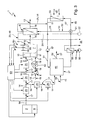
Bei der in Fig. 2 gezeigten Ausführungsform weist die Antriebseinrichtung 27 eine Brennstoffzelle 29 sowie einen Elektromotor 30 auf. Die Brennstoffzelle 29 dient zum Generieren von elektrischem Strom aus einem wasserstoffhaltigen Anodengas und einen sauerstoffhaltigen Kathodengas. Als Anodengas wird das Wasserstoffgas 14 verwendet, so dass im folgenden auch das Anodengas mit 14 bezeichnet wird. Als Kathodengas wird zweckmäßig Luft verwendet, die auch als Oxidatorgas 15 dient, so dass im folgenden das Kathodengas ebenfalls mit 15 bezeichnet wird. Die Brennstoffzelle 29 weist einen Anodengaseingang 30 auf, an den ein Zweig der Wasserstoffleitung 17 angeschlossen ist. Besagter Zweig geht beispielsweise zwischen dem Sperr-/Überströmventil 23 und dem Druckbegrenzer 24 von dem mit dem Wasserstofftank 2 verbundenen Abschnitt der Wasserstoffleitung 17 ab. In diesem Zweig sind zweckmäßig ebenfalls ein Druckbegrenzer 24 und eine Dosiereinheit 25 angeordnet, wobei letztere so ausgestaltet ist, dass sie die von der Brennstoffzelle 29 jeweils benötigte Wasserstoffmenge zumessen bzw. absperren kann, damit die Brennstoffzelle 29 die jeweils benötigte elektrische Energie bereitstellen kann. Desweiteren weist die Brennstoffzelle 29 einen Kathodengaseingang 32 auf, an den eine Kathodengaszuführeinrichtung 33 angeschlossen ist. Diese umfasst eine Kathodengasleitung 34, die an den Kathodengaseingang 32 angeschlossen ist, sowie eine Fördereinrichtung 35, z.B. eine Pumpe oder ein Gebläse. Die Brennstoffzelle 29 enthält eine Anodenseite 36 und eine Kathodenseite 37, die insbesondere durch einen Elektrolyten 38 voneinander getrennt sind. Im Betrieb der Brennstoffzelle 29 wird Wasserstoff umgesetzt bzw. verstromt, so dass an wenigstens einem Stromanschluss 39 elektrischer Strom 40 an der Brennstoffzelle 29 abgreifbar ist. Der Elektromotor 30 ist nun elektrisch an die Brennstoffzelle 29 angeschlossen, also mit dem elektrischen Anschluss 39 verbunden.In the embodiment shown in FIG. 2, the
Die Brennstoffzelle 29 kann z.B. als Hochtemperatur-Brennstoffzelle, insbesondere als Festkörper-Brennstoffzelle (sogenannte "SOFC"-Brennstoffzelle) ausgestaltet sein. Die Arbeitstemperatur einer derartigen Hochtemperatur-Brennstoffzelle liegt im Maximum bei etwa 850° C. Alternativ kann die Brennstoffzelle 29 auch als Niedertemperatur-Brennstoffzelle ausgestaltet sein. Beispielsweise handelt es sich hierbei um eine Brennstoffzelle 29, die mit einer Protonenaustauschmembran bzw. mit einer polymeren Elektrolytmembran arbeitet, sogenannte "PEM"-Brennstoffzelle. Die Arbeitstemperatur einer derartigen Niedertemperatur-Brennstoffzelle liegt im Maximum bei etwa 80° bis 150° C. Bei einer Niedertemperatur-Brennstoffzelle, insbesondere bei einer PEM-Brennstoffzelle, ist es üblich, das Kathodengas 15 mit einem relativ hohen Anteil an Wasserdampf zu versehen. Das Wasser unterstützt den Brennstoffzellenprozess am Elektrolyt 38. Dementsprechend kann gemäß Fig. 2 die Wasserstoffheizung 1 optional mit einer Einspeiseinrichtung 68 ausgestattet sein, mit deren Hilfe Wasserdampf in das Kathodengas 15 einbringbar ist. Die Einspeiseinrichtung 68 ist hierzu beispielsweise stromauf des Kathodengaseingangs 32 in der Kathodengasleitung 34 angeordnet. Für den Verbrennungsprozess im Brenner 3 ist ein hoher Wasseranteil im Gemisch unerwünscht. Dementsprechend kann optional eine Entnahmeeinrichtung 69 vorgesehen sein. Mit Hilfe der Entnahmeeinrichtung 69 kann dem Kathodenabgas 46 Wasserdampf entzogen werden. Vorzugsweise ist die Entnahmeeinrichtung 69 hierzu in einer Kathodenabgasleitung 70 angeordnet, die den Kathodenabgasausgang 43 der Brennstoffzelle 29 mit dem Kathodenabgaseingang 47 des Brenners 3 verbindet. Zwischen der Entnahmeeinrichtung 69 und der Einspeiseinrichtung 68 kann eine Wirkverbindung 71 bestehen, die hier durch eine unterbrochene Linie angedeutet ist. Durch diese Wirkverbindung 71 kann der mit Hilfe der Entnahmeeinrichtung 69 dem Kathodenabgas 46 entnommene Wasserdampf der Einspeiseinrichtung 68 zum Einspeisen in das Kathodengas 15 zugeführt werden. Diese Wirkverbindung 71 kann eine Fördereinrichtung für Wasser bzw. Wasserdampf aufweisen. Besonders vorteilhaft ist eine Ausführungsform, bei welcher die Einspeiseinrichtung 68 und die Entnahmeeinrichtung 69 eine bauliche Einheit bilden, so dass die Wirkverbindung 71 im Inneren einer derartigen kombinierten Einspeis- und Entnahmeeinrichtung angeordnet ist. Die Verwendung einer derartigen kombinierten Einspeis- und Entnahmeeinrichtung ist beispielsweise durch einen entsprechenden Verlauf der Kathodenabgasleitung 70 und/oder der Kathodengasleitung 34 realisierbar.The
Üblicherweise besteht eine derartige Brennstoffzelle 29 aus einem Stapel einzelner Brennstoffzellenelemente, wobei ein derartiger Stapel ausgangsseitig durch eine Abschlussplatte 41 begrenzt ist. Besagte Abschlussplatte 41 enthält einen Anodenabgasausgang 42 sowie einen Kathodenabgasausgang 42 der Brennstoffzelle 29. Über den Anodenabgasausgang 42 gelangt wasserstoffhaltiges Anodenabgas 44 zu einem Anodenabgaseingang 45 des Brenners 3. Der Anodenabgaseingang 45 kommuniziert dabei mit dem ersten Verteilerpfad 10, so dass der erste Verteilerpfad 10 einen Anodenabgaseingangsbereich des Brenners 3 bildet. Auf entsprechende Weise gelangt Kathodenabgas 46 vom Kathodenabgasausgang 43 über einen Kathodenabgaseingang 47 des Brenners 3 in den zweiten Verteilerpfad 11. Dementsprechend bildet der zweite Verteilerpfad 11 einen Kathodenabgaseingangsbereich des Brenners 3. Bemerkenswert ist nun, dass der Brenner 3 unabhängig von der Brennstoffzelle 29 ebenfalls an den Wasserstofftank 2 angeschlossen ist, wobei der entsprechende Zweig der Wasserstoffleitung 17 über den ersten Eingang 8 ebenfalls an den Anodenabgaseingangsbereich 10 angeschlossen ist. Auf entsprechende Weise ist die Oxidatorzuführeinrichtung 4 über den zweiten Eingang 9 an den Kathodenabgaseingangsbereich 11 des Brenners 3 angeschlossen. Grundsätzlich ist es möglich, die Oxidatorzuführeinrichtung 4 und die Kathodengaszuführeinrichtung 33 baulich miteinander zu kombinieren, sofern für das Oxidatorgas und das Kathodengas das gleiche Gas, insbesondere Luft, verwendet wird.Typically, such a
Die Abgase der Brennstoffzelle 29 enthalten aufgrund der darin unvollständigen Umsetzung nach wie vor Wasserstoff und Sauerstoff und können im Brenner 3 zur Erzeugung von Wärme genutzt werden. Sofern die Wärmeleistung des Brenners 3, die allein durch die Abgase der Brennstoffzelle 29 erzielbar ist, nicht ausreicht, wird dem Brenner 3 direkt aus dem Wasserstofftank 2 Wasserstoffgas 14 und über die Oxidatorzuführeinrichtung 4 direkt Oxidatorgas 15 zugemessen.The exhaust gases of the
Zum Beheizen des Fahrzeuginnenraums 28 ist der Wärmeübertrager 5 der Wasserstoffheizung 1 bei der in Fig. 2 gezeigten Ausführungsform in einen Warmluftkanal 48 des Fahrzeugs eingebunden. Besagter Warmluftkanal 48 ist hier durch den Heizpfad 20 gebildet und bildet einen Bestandteil einer Innenraumheizung des Fahrzeugs. Das vom Brennerabgas 16 aufgeheizte Heizmedium 21 bildet in diesem Fall die dem Fahrzeuginnenraum 28 zugeführte Warmluft. Insoweit kann die Wasserstoffheizung 1 zur direkten Beheizung des Fahrzeuginnenraums 28 genutzt werden. Bei einer anderen Anwendung kann die Wasserstoffheizung 1 z.B. auch in ein sogenanntes Klimamodul als Heizeinrichtung eingebaut werden. Klimamodule oder sogenannte HVAC-Anlagen, wobei "HVAC" für Heater, Ventilation und Air Condition steht, sind kombinierte Systeme zum Beheizen, Belüften, Kühlen oder allgemein zum Klimatisieren von Räumen, insbesondere in Kraftfahrzeugen.For heating the
Bei einer besonderen Ausgestaltung der in Fig. 2 gezeigten Ausführungsform kann der Brenner 3 baulich in die Brennstoffzelle 29 integriert werden, derart, dass der Brenner 3 besagte Abschlussplatte 41 ersetzt bzw. die Abschlussplatte 41 bildet. Hierdurch kann eine besonders kompakte Bauform erreicht werden.In a particular embodiment of the embodiment shown in Fig. 2, the
Bei der in Fig. 3 gezeigten Ausführungsform umfasst die Antriebseinrichtung 27 einen mit Wasserstoff betreibbaren Verbrennungsmotor 49, der in einen Kühlkreis 50 eingebunden ist. Im Kühlkreis 50 zirkuliert ein Kühlmedium 51. Zum Antrieb des Kühlmediums 51 enthält der Kühlkreis 50 eine Fördereinrichtung 52, z.B. eine Pumpe oder ein Gebläse. Im Kühlkreis 50 kann optional ein Wärmeübertrager 53 angeordnet sein, der üblicherweise als Fahrzeugkühler bezeichnet wird und der im Betrieb des Fahrzeugs mit einer Luftströmung 54 beaufschlagt ist.In the embodiment shown in FIG. 3, the
Der Verbrennungsmotor 49 ist über einen entsprechenden Zweig der Wasserstoffleitung 17 an den Wasserstofftank 2 angeschlossen. Besagter Zweig geht von dem mit dem Wasserstofftank 2 verbundenen Abschnitt der Wasserstoffleitung 17 am zwischen dem Sperr-/ Überströmventil 23 und dem Druckbegrenzer 24 ab und enthält vorzugsweise ebenfalls einen Druckbegrenzer 24 sowie eine weitere Dosiereinheit 25. Zweckmäßig befindet sich diese Dosiereinheit 25 unmittelbar am Verbrennungsmotor 49, z.B. in Form einer Eindüs- oder Einspritzeinrichtung, die den einzelnen Zylindern des Verbrennungsmotor 49 zugeordnet ist. Der Verbrennungsmotor 49 ist außerdem an eine Frischgasleitung 55 angeschlossen, über die der Verbrennungsmotor 49 ein sauerstoffhaltiges Frischgas, zweckmäßig Luft, erhält. Das Frischgas kann in seiner Konsistenz dem Oxidatorgas entsprechen und wird im folgenden daher ebenfalls mit 15 bezeichnet. Der Verbrennungsmotor 49 erzeugt im Betrieb durch die Verbrennung von Wasserstoffgas mit Frischgas 15 Motorabgas 56, das über eine entsprechende Abgasleitung 57 abgeführt wird.The
Grundsätzlich ist es bei dieser Ausführungsform ebenfalls möglich, den Wärmeübertrager 5 der Wasserstoffheizung 1 direkt zur Beheizung des Fahrzeuginnenraums 28 zu verwenden. Ein entsprechender Heizpfad 20 bzw. ein entsprechender Warmluftkanal 48 sind in Fig. 3 durch unterbrochene Linien angedeutet. Alternativ oder auch zusätzlich erfolgt die Beheizung des Fahrzeuginnenraums 28 mit Hilfe eines Warmluftkanals 58, der über einen weiteren Wärmeübertrager 59 mit dem Kühlkreis 50 des Verbrennungsmotors 49 wärmeübertragend gekoppelt ist. Auf diese Weise kann im Betrieb des Kühlkreises 50 das erhitzte Kühlmedium 51 Wärme über besagten Wärmeübertrager 59 in im Warmluftkanal 48 transportierte Luft eingebracht werden, um so Warmluft zu erzeugen, die dann den Fahrzeuginnenraum 28 zugeführt werden kann. Hierzu enthält besagter Warmluftkanal 48 außerdem eine geeignete Fördereinrichtung 60, insbesondere eine Pumpe oder ein Gebläse. Bei dieser Ausführungsform erfolgt die Beheizung des Fahrzeuginnenraums 28 mit Hilfe der Wärme im Kühlkreis 50.In principle, it is also possible in this embodiment to use the
Zweckmäßig ist nun der Wärmeübertrager 5 der Wasserstoffheizung 1 in den Kühlkreis 50 des Verbrennungsmotors 49 eingebunden. Ein Steuerventil 61 steuert dabei die Durchströmung des Wärmeübertragers 5 mit dem Kühlmedium 51, das bei dieser Ausführungsform das Heizmedium des Wärmeübertragers 5, also das mit Hilfe der heißen Brennerabgase 16 beheizbare Heizmedium bildet. Der Wärmeübertrager 5 ist vorzugsweise parallel zum Fahrzeugkühler 53 des Kühlkreises 50 angeordnet und kann bei entsprechender Ansteuerung des Steuerventils 61 einen Bypass zum Fahrzeugkühler 53 bilden. Auf diese Weise kann im Bedarfsfall dem Kühlmedium 51 Wärme zugeführt werden, beispielsweise um den Verbrennungsmotor 49 möglichst rasch auf seine optimale Betriebstemperatur zu bringen und/oder um dem Kühlkreis 50 über den Wärmeübertrager 59 des Warmluftkanals 58 hinreichend Wärme zur Beheizung des Fahrzeuginnenraums 28 entziehen zu können. Die Wasserstoffheizung 1 wird dann zur indirekten Beheizung des Innenraums 28 genutzt.Expediently, the
Alternativ ist es auch hier möglich, die Wasserstoffheizung 1 als Heizeinrichtung in einem Klimamodul bzw. in einer HVAC-Anlage zu verwenden.Alternatively, it is also possible here to use the hydrogen heater 1 as a heating device in a climate module or in an HVAC system.
Bei einer besonders kompakten Ausführungsform der in den Fig. 1 bis 3 gezeigten Wasserstoffheizung 1 kann der Wärmeübertrager 5 baulich in den Brenner 3 integriert sein, und zwar so, dass der Wärmeübertrager 5 den Brennraum 7 ausgangsseitig begrenzt. Somit treten die heißen Brennerabgase 16 unmittelbar durch den Wärmeübertrager 5 aus dem Brenner 3 aus.In a particularly compact embodiment of the hydrogen heater 1 shown in FIGS. 1 to 3, the
Bei der Wasserstoffheizung 1 kann der Brenner 3 unter anderem auch dazu verwendet werden, überschüssigen Wasserstoff 14 kontrolliert zu verbrennen, um eine Schadstoffbelastung der Umgebung zu vermeiden. Dies ist insbesondere dann von Vorteil, wenn ein Wasserstofftank 2 verwendet wird, bei dem der Wasserstoff in flüssigem Zustand bei tiefen Temperaturen bereitgestellt wird. Trotz bester Isolierungsmaßnahmen strebt der flüssige Wasserstoff stets einen Temperaturausgleich mit der Umgebung an, wobei es zu einer Verdampfung eines Teils des Wasserstoffs kommt, die zu einem Druckanstieg im Wasserstofftank 2 führt. Das Überströmventil 23 und der Brenner 3 können über die Steuerung 63 gezielt so betätigt werden, dass bei Erreichen eines vorbestimmten Maximaldrucks für eine kurze Zeit der Brenner 3 betrieben wird, um dieses überschüssige Wasserstoffgas zu entsorgen. Durch Absenkung des Drucks auf einen vorbestimmten Minimaldruck kann ein Regelverhalten mit einer Hysterese erzielt werden, so dass der Brenner 3 nur in vergleichsweise großen Abständen für kurze Zeitspannen betrieben werden muss. Die bei diesem Entspannungsvorgang des Wasserstofftanks 2 generierte Wärme kann z.B. zum Beheizen der Antriebseinrichtung 27 und/oder des Fahrzeuginnenraums 28 verwendet werden.In the case of the hydrogen heater 1, the
Claims (12)
dadurch gekennzeichnet,
characterized,
dadurch gekennzeichnet, dass die Wasserstoffheizung (1) als Standheizung oder als Zuheizer eines Kraftfahrzeugs ausgestaltet ist.Hydrogen heater according to claim 1,
characterized, that the hydrogen heating (1) is designed as a heater or as a heater of a motor vehicle.
dadurch gekennzeichnet,
characterized,
dadurch gekennzeichnet,
characterized,
dadurch gekennzeichnet,
dass der Wasserstofftank (2) an einen Anodengaseingang (31) der Brennstoffzelle (29) angeschlossen ist, derart, dass das Wasserstoffgas (14) des Wasserstofftanks (2) das Anodengas der Brennstoffzelle (29) bildet.Hydrogen burner according to claim 5,
characterized,
in that the hydrogen tank (2) is connected to an anode gas inlet (31) of the fuel cell (29) such that the hydrogen gas (14) of the hydrogen tank (2) forms the anode gas of the fuel cell (29).
dadurch gekennzeichnet,
characterized,
dadurch gekennzeichnet,
dass der Wärmeübertrager (5) der Wasserstoffheizung (1) in einen Warmluftkanal (48) einer Innenraumheizung des Fahrzeugs eingebunden ist, derart, dass im Betrieb der Wasserstoffheizung (1) das vom Brennerabgas (16) erwärmte Heizmedium (21) die dem Fahrzeuginnenraum (28) zugeführte Warmluft bildet.Hydrogen heater according to one of claims 5 to 7,
characterized,
that the heat exchanger (5) of the water fuel (1) is integrated into a hot air passage (48) of an inner space heating of the vehicle, such that the by the burner exhaust gas (16) heated during operation of the hydrogen heating (1) a heating medium (21) that (the vehicle interior 28 ) forms supplied hot air.
dadurch gekennzeichnet, dass der Wärmeübertrager (5) der Wasserstoffheizung (1) in den Kühlkreis (50) des Verbrennungsmotors (49) eingebunden ist, derart, dass das Kühlmedium (51) des Kühlkreises (50) das Heizmedium (21) bildet.Hydrogen heater according to claim 7,
characterized, that the heat exchanger (5) of the water fuel (1) in the cooling circuit (50) of the internal combustion engine (49) is integrated, such that the cooling medium (51) of the cooling circuit (50) constitutes the heating medium (21).
dadurch gekennzeichnet, dass in den Kühlkreis (50) ein weiterer Wärmeübertrager (59) eingebunden ist, der außerdem in einen Warmluftkanal (58) einer Innenraumheizung des Fahrzeugs eingebunden ist, derart, dass im Betrieb des Kühlkreises (50) die dem Fahrzeuginnenraum (28) zugeführte Warmluft durch das Kühlmedium (51) erwärmbar ist.Hydrogen heater according to claim 9,
characterized in that in the cooling circuit (50), a further heat exchanger (59) is integrated, which is also involved in a hot air duct (58) of an interior heating of the vehicle, such that during operation of the cooling circuit (50) which the vehicle interior (28) supplied hot air through the cooling medium (51) is heated.
dadurch gekennzeichnet,
characterized,
dadurch gekennzeichnet,
dass eine Steuerung (63) zum Betreiben des Brenners (3) vorgesehen ist, die so ausgestaltet ist, dass damit vom Wasserstofftank (2) abzuführendes Wasserstoffgas (14) automatisch mit Oxidatorgas (15) verbrennbar ist.Hydrogen heater according to one of claims 1 to 11,
characterized,
in that a controller (63) is provided for operating the burner (3), which is designed so that hydrogen gas (14) to be discharged from the hydrogen tank (2) can be burned automatically with oxidizing gas (15).
Applications Claiming Priority (1)
| Application Number | Priority Date | Filing Date | Title |
|---|---|---|---|
| DE102006046256A DE102006046256A1 (en) | 2006-09-28 | 2006-09-28 | Hydrogen Heating |
Publications (2)
| Publication Number | Publication Date |
|---|---|
| EP1906108A2 true EP1906108A2 (en) | 2008-04-02 |
| EP1906108A3 EP1906108A3 (en) | 2014-09-03 |
Family
ID=38963229
Family Applications (1)
| Application Number | Title | Priority Date | Filing Date |
|---|---|---|---|
| EP07113899.4A Withdrawn EP1906108A3 (en) | 2006-09-28 | 2007-08-07 | Hydrogen heating |
Country Status (2)
| Country | Link |
|---|---|
| EP (1) | EP1906108A3 (en) |
| DE (1) | DE102006046256A1 (en) |
Cited By (4)
| Publication number | Priority date | Publication date | Assignee | Title |
|---|---|---|---|---|
| GB2458949A (en) * | 2008-04-04 | 2009-10-07 | Charles Alvin Scott | Production of hydrogen via batteries as a fuel source. |
| ITCO20100037A1 (en) * | 2010-07-26 | 2012-01-26 | Giacomini Spa | "HYDROGEN ENERGY PRODUCTION SYSTEM, IN PARTICULAR FOR HOUSES" |
| SE543923C2 (en) * | 2019-01-29 | 2021-09-28 | Scania Cv Ab | A vehicle assembly and a vehicle |
| EP3978281A1 (en) * | 2020-09-30 | 2022-04-06 | Siemens Mobility GmbH | Vehicle with catalytic burner for air conditioning a passenger compartment |
Families Citing this family (4)
| Publication number | Priority date | Publication date | Assignee | Title |
|---|---|---|---|---|
| DE102009012188A1 (en) * | 2009-02-26 | 2010-09-02 | Nesković, Branko | Hydrogen heater for use as e.g. building heater, has spiral-shaped pipe system for transmitting heat from combustion gases to heat exchanger, where system is integrated into building circuit, and exchanger transmits heat to heating medium |
| DE102019128266A1 (en) * | 2019-10-21 | 2021-04-22 | Audi Ag | Motor vehicle with an electrical energy store and method for operating a motor vehicle |
| DE102022000430A1 (en) | 2022-01-26 | 2023-07-27 | Apodis Gmbh | Fuel cell system for a fuel cell vehicle |
| DE102022000431A1 (en) | 2022-01-26 | 2023-07-27 | Apodis Gmbh | Fuel cell system for a fuel cell vehicle |
Citations (3)
| Publication number | Priority date | Publication date | Assignee | Title |
|---|---|---|---|---|
| EP1403106A2 (en) * | 2002-09-26 | 2004-03-31 | J. Eberspächer GmbH & Co. KG | Heating system for a motor vehicle |
| EP1439082A2 (en) * | 2003-01-17 | 2004-07-21 | J. Eberspächer GmbH & Co. KG | Apparatus for conditioning a vehicle |
| WO2005024301A1 (en) * | 2003-09-11 | 2005-03-17 | Giacomini S.P.A. | Hydrogen burning method and burner, and water heating system using it |
Family Cites Families (7)
| Publication number | Priority date | Publication date | Assignee | Title |
|---|---|---|---|---|
| DE53393C (en) * | C. WlLKE in Schmalkalden | Oxyhydrogen or Hydrogen heating | ||
| DE2911178A1 (en) * | 1979-03-22 | 1980-10-02 | Hans Dipl Ing Kuehl | Chemical reaction utilising room heater - uses reaction agents whose gaseous prod. is not detrimental to health, or does not impair breathing |
| US5092281A (en) * | 1988-07-26 | 1992-03-03 | Kabushiki Kaisha Toyoda Jidoshokki Seisakusho | Hydrogen engine system |
| US6716400B2 (en) * | 2001-03-09 | 2004-04-06 | Honda Giken Kogyo Kabushiki Kaisha | Ignition system for a fuel cell hydrogen generator |
| DE102004033545B4 (en) * | 2004-07-09 | 2006-06-14 | J. Eberspächer GmbH & Co. KG | burner |
| DE102004017340A1 (en) * | 2004-07-29 | 2006-03-23 | Liebert, Heinz | Hydrogen-fired boiler or oven is useful e.g. for combustion in power station, heating power station, refuse incinerating power station, heat source, energy, heat and steam generator or petrochemical cracker |
| DE102004045638A1 (en) * | 2004-09-21 | 2006-04-06 | Bayerische Motoren Werke Ag | Heat exchanger for hydrogen-powered fuel supply systems |
-
2006
- 2006-09-28 DE DE102006046256A patent/DE102006046256A1/en not_active Withdrawn
-
2007
- 2007-08-07 EP EP07113899.4A patent/EP1906108A3/en not_active Withdrawn
Patent Citations (3)
| Publication number | Priority date | Publication date | Assignee | Title |
|---|---|---|---|---|
| EP1403106A2 (en) * | 2002-09-26 | 2004-03-31 | J. Eberspächer GmbH & Co. KG | Heating system for a motor vehicle |
| EP1439082A2 (en) * | 2003-01-17 | 2004-07-21 | J. Eberspächer GmbH & Co. KG | Apparatus for conditioning a vehicle |
| WO2005024301A1 (en) * | 2003-09-11 | 2005-03-17 | Giacomini S.P.A. | Hydrogen burning method and burner, and water heating system using it |
Cited By (7)
| Publication number | Priority date | Publication date | Assignee | Title |
|---|---|---|---|---|
| GB2458949A (en) * | 2008-04-04 | 2009-10-07 | Charles Alvin Scott | Production of hydrogen via batteries as a fuel source. |
| GB2458949B (en) * | 2008-04-04 | 2010-11-17 | Charles Alvin Scott | Low-voltage electricals to enable containment of hydrogen |
| ITCO20100037A1 (en) * | 2010-07-26 | 2012-01-26 | Giacomini Spa | "HYDROGEN ENERGY PRODUCTION SYSTEM, IN PARTICULAR FOR HOUSES" |
| US20120037153A1 (en) * | 2010-07-26 | 2012-02-16 | Giacomini S.P.A. | System for producing energy from hydrogen, in particular for residential buildings |
| WO2012020288A3 (en) * | 2010-07-26 | 2013-10-17 | Giacomini S.P.A. | System for producing energy from hydrogen, in particular for residential buildings |
| SE543923C2 (en) * | 2019-01-29 | 2021-09-28 | Scania Cv Ab | A vehicle assembly and a vehicle |
| EP3978281A1 (en) * | 2020-09-30 | 2022-04-06 | Siemens Mobility GmbH | Vehicle with catalytic burner for air conditioning a passenger compartment |
Also Published As
| Publication number | Publication date |
|---|---|
| EP1906108A3 (en) | 2014-09-03 |
| DE102006046256A1 (en) | 2008-04-03 |
Similar Documents
| Publication | Publication Date | Title |
|---|---|---|
| EP1906108A2 (en) | Hydrogen heating | |
| DE102007039594B4 (en) | Energy generation unit with at least one high-temperature fuel cell | |
| EP1616361B1 (en) | Energy converting device, and reformer unit and fuel cell unit therefor | |
| DE102005034404A1 (en) | Gas supply system and method | |
| DE102004002337A1 (en) | An energy conversion device and method of operating the energy conversion device | |
| DE102011088563A1 (en) | Arrangement with fuel cell system | |
| EP1947723B1 (en) | System for providing energy | |
| DE10142578A1 (en) | System for generating electrical energy and method for operating a system for generating electrical energy | |
| EP1921703B1 (en) | Fuel cell system with means for preheating cathode air | |
| DE102006003740B4 (en) | Method and system for operating a high temperature fuel cell | |
| EP2526344B1 (en) | Method for operating a cogeneration plant | |
| EP0613588B1 (en) | Process and device for disengaging heat from fuel cells | |
| EP1986263B1 (en) | Fuel cell system and appropriate starting method | |
| DE10343264A1 (en) | The fuel cell system | |
| EP1297582A2 (en) | Method for regulating operation of fuel cell installations controlled according to heat and/or power requirement | |
| DE10324213A1 (en) | fuel cell device | |
| DE10107596B4 (en) | Low temperature fuel cell device for vehicles, in particular PEM (Proton Exchange Membrane) fuel cell device | |
| DE10028331C2 (en) | Fuel cell system and method for starting up a fuel cell system and use of the fuel cell system | |
| DE102016214866B4 (en) | Fuel cell cogeneration system, method for starting operation of the fuel cell cogeneration system and method for operating the fuel cell cogeneration system | |
| DE102007033150B4 (en) | Operating method for a fuel cell system | |
| DE102014222839A1 (en) | Fuel cell device with integrated heat storage | |
| DE102008027292A1 (en) | Fuel cell system and thus equipped motor vehicle | |
| EP1906478B1 (en) | Fuel cell system | |
| DE102010047523A1 (en) | Fuel cell system for use in e.g. ships, has air inlet pipe placed between burner and compressor in flow direction subsequent to compressor components, where hot exhaust gases of burner flow from cathode region of fuel cell | |
| DE202006008898U1 (en) | Fuel cell system for vehicles has reformate burner arrangement that sends incineration gases to fuel cell before and after anti-condensation temperature is reached by remaining hydrocarbons and water vapor in reformer |
Legal Events
| Date | Code | Title | Description |
|---|---|---|---|
| PUAI | Public reference made under article 153(3) epc to a published international application that has entered the european phase |
Free format text: ORIGINAL CODE: 0009012 |
|
| AK | Designated contracting states |
Kind code of ref document: A2 Designated state(s): AT BE BG CH CY CZ DE DK EE ES FI FR GB GR HU IE IS IT LI LT LU LV MC MT NL PL PT RO SE SI SK TR |
|
| AX | Request for extension of the european patent |
Extension state: AL BA HR MK YU |
|
| RIC1 | Information provided on ipc code assigned before grant |
Ipc: B60H 1/00 20060101ALI20130829BHEP Ipc: F24H 1/00 20060101AFI20130829BHEP |
|
| RAP1 | Party data changed (applicant data changed or rights of an application transferred) |
Owner name: EBERSPAECHER CLIMATE CONTROL SYSTEMS GMBH & CO. KG |
|
| PUAL | Search report despatched |
Free format text: ORIGINAL CODE: 0009013 |
|
| RIC1 | Information provided on ipc code assigned before grant |
Ipc: F24H 3/06 20060101ALI20140722BHEP Ipc: B60H 1/00 20060101ALI20140722BHEP Ipc: F24H 1/00 20060101AFI20140722BHEP |
|
| AK | Designated contracting states |
Kind code of ref document: A3 Designated state(s): AT BE BG CH CY CZ DE DK EE ES FI FR GB GR HU IE IS IT LI LT LU LV MC MT NL PL PT RO SE SI SK TR |
|
| AX | Request for extension of the european patent |
Extension state: AL BA HR MK RS |
|
| RIC1 | Information provided on ipc code assigned before grant |
Ipc: F24H 1/00 20060101AFI20140728BHEP Ipc: F24H 3/06 20060101ALI20140728BHEP Ipc: B60H 1/00 20060101ALI20140728BHEP |
|
| 17P | Request for examination filed |
Effective date: 20150213 |
|
| RBV | Designated contracting states (corrected) |
Designated state(s): AT BE BG CH CY CZ DE DK EE ES FI FR GB GR HU IE IS IT LI LT LU LV MC MT NL PL PT RO SE SI SK TR |
|
| AKX | Designation fees paid |
Designated state(s): DE FR GB NL SE |
|
| AXX | Extension fees paid |
Extension state: HR Extension state: RS Extension state: AL Extension state: MK Extension state: BA |
|
| STAA | Information on the status of an ep patent application or granted ep patent |
Free format text: STATUS: THE APPLICATION IS DEEMED TO BE WITHDRAWN |
|
| 18D | Application deemed to be withdrawn |
Effective date: 20160301 |