EP1905966A1 - Multicylinder internal combustion engine - Google Patents
Multicylinder internal combustion engine Download PDFInfo
- Publication number
- EP1905966A1 EP1905966A1 EP07015637A EP07015637A EP1905966A1 EP 1905966 A1 EP1905966 A1 EP 1905966A1 EP 07015637 A EP07015637 A EP 07015637A EP 07015637 A EP07015637 A EP 07015637A EP 1905966 A1 EP1905966 A1 EP 1905966A1
- Authority
- EP
- European Patent Office
- Prior art keywords
- cylinders
- cylinder
- valve
- internal combustion
- combustion engine
- Prior art date
- Legal status (The legal status is an assumption and is not a legal conclusion. Google has not performed a legal analysis and makes no representation as to the accuracy of the status listed.)
- Granted
Links
- 238000002485 combustion reaction Methods 0.000 title claims abstract description 52
- 230000007246 mechanism Effects 0.000 description 26
- 238000010276 construction Methods 0.000 description 13
- 230000009467 reduction Effects 0.000 description 10
- 230000000694 effects Effects 0.000 description 9
- 239000000446 fuel Substances 0.000 description 8
- 230000009849 deactivation Effects 0.000 description 7
- 230000008901 benefit Effects 0.000 description 5
- 238000001514 detection method Methods 0.000 description 4
- 230000001133 acceleration Effects 0.000 description 3
- 230000008859 change Effects 0.000 description 3
- 238000010586 diagram Methods 0.000 description 3
- 238000010304 firing Methods 0.000 description 3
- 238000002347 injection Methods 0.000 description 2
- 239000007924 injection Substances 0.000 description 2
- 238000003780 insertion Methods 0.000 description 2
- 230000037431 insertion Effects 0.000 description 2
- 238000004891 communication Methods 0.000 description 1
- 238000001816 cooling Methods 0.000 description 1
- 230000003247 decreasing effect Effects 0.000 description 1
- 230000009969 flowable effect Effects 0.000 description 1
- 230000004907 flux Effects 0.000 description 1
- 230000012447 hatching Effects 0.000 description 1
- 230000000717 retained effect Effects 0.000 description 1
Images





Classifications
-
- F—MECHANICAL ENGINEERING; LIGHTING; HEATING; WEAPONS; BLASTING
- F01—MACHINES OR ENGINES IN GENERAL; ENGINE PLANTS IN GENERAL; STEAM ENGINES
- F01L—CYCLICALLY OPERATING VALVES FOR MACHINES OR ENGINES
- F01L13/00—Modifications of valve-gear to facilitate reversing, braking, starting, changing compression ratio, or other specific operations
- F01L13/0005—Deactivating valves
-
- F—MECHANICAL ENGINEERING; LIGHTING; HEATING; WEAPONS; BLASTING
- F01—MACHINES OR ENGINES IN GENERAL; ENGINE PLANTS IN GENERAL; STEAM ENGINES
- F01L—CYCLICALLY OPERATING VALVES FOR MACHINES OR ENGINES
- F01L1/00—Valve-gear or valve arrangements, e.g. lift-valve gear
- F01L1/02—Valve drive
- F01L1/022—Chain drive
-
- F—MECHANICAL ENGINEERING; LIGHTING; HEATING; WEAPONS; BLASTING
- F01—MACHINES OR ENGINES IN GENERAL; ENGINE PLANTS IN GENERAL; STEAM ENGINES
- F01L—CYCLICALLY OPERATING VALVES FOR MACHINES OR ENGINES
- F01L1/00—Valve-gear or valve arrangements, e.g. lift-valve gear
- F01L1/12—Transmitting gear between valve drive and valve
- F01L1/14—Tappets; Push rods
- F01L1/143—Tappets; Push rods for use with overhead camshafts
-
- F—MECHANICAL ENGINEERING; LIGHTING; HEATING; WEAPONS; BLASTING
- F02—COMBUSTION ENGINES; HOT-GAS OR COMBUSTION-PRODUCT ENGINE PLANTS
- F02B—INTERNAL-COMBUSTION PISTON ENGINES; COMBUSTION ENGINES IN GENERAL
- F02B75/00—Other engines
- F02B75/16—Engines characterised by number of cylinders, e.g. single-cylinder engines
- F02B75/18—Multi-cylinder engines
- F02B75/20—Multi-cylinder engines with cylinders all in one line
-
- F—MECHANICAL ENGINEERING; LIGHTING; HEATING; WEAPONS; BLASTING
- F02—COMBUSTION ENGINES; HOT-GAS OR COMBUSTION-PRODUCT ENGINE PLANTS
- F02B—INTERNAL-COMBUSTION PISTON ENGINES; COMBUSTION ENGINES IN GENERAL
- F02B75/00—Other engines
- F02B75/16—Engines characterised by number of cylinders, e.g. single-cylinder engines
- F02B75/18—Multi-cylinder engines
- F02B75/22—Multi-cylinder engines with cylinders in V, fan, or star arrangement
-
- F—MECHANICAL ENGINEERING; LIGHTING; HEATING; WEAPONS; BLASTING
- F02—COMBUSTION ENGINES; HOT-GAS OR COMBUSTION-PRODUCT ENGINE PLANTS
- F02D—CONTROLLING COMBUSTION ENGINES
- F02D13/00—Controlling the engine output power by varying inlet or exhaust valve operating characteristics, e.g. timing
- F02D13/02—Controlling the engine output power by varying inlet or exhaust valve operating characteristics, e.g. timing during engine operation
- F02D13/06—Cutting-out cylinders
-
- F—MECHANICAL ENGINEERING; LIGHTING; HEATING; WEAPONS; BLASTING
- F02—COMBUSTION ENGINES; HOT-GAS OR COMBUSTION-PRODUCT ENGINE PLANTS
- F02D—CONTROLLING COMBUSTION ENGINES
- F02D9/00—Controlling engines by throttling air or fuel-and-air induction conduits or exhaust conduits
- F02D9/08—Throttle valves specially adapted therefor; Arrangements of such valves in conduits
- F02D9/10—Throttle valves specially adapted therefor; Arrangements of such valves in conduits having pivotally-mounted flaps
- F02D9/109—Throttle valves specially adapted therefor; Arrangements of such valves in conduits having pivotally-mounted flaps having two or more flaps
-
- F—MECHANICAL ENGINEERING; LIGHTING; HEATING; WEAPONS; BLASTING
- F02—COMBUSTION ENGINES; HOT-GAS OR COMBUSTION-PRODUCT ENGINE PLANTS
- F02M—SUPPLYING COMBUSTION ENGINES IN GENERAL WITH COMBUSTIBLE MIXTURES OR CONSTITUENTS THEREOF
- F02M35/00—Combustion-air cleaners, air intakes, intake silencers, or induction systems specially adapted for, or arranged on, internal-combustion engines
- F02M35/10—Air intakes; Induction systems
- F02M35/10006—Air intakes; Induction systems characterised by the position of elements of the air intake system in direction of the air intake flow, i.e. between ambient air inlet and supply to the combustion chamber
- F02M35/10026—Plenum chambers
- F02M35/10032—Plenum chambers specially shaped or arranged connecting duct between carburettor or air inlet duct and the plenum chamber; specially positioned carburettors or throttle bodies with respect to the plenum chamber
-
- F—MECHANICAL ENGINEERING; LIGHTING; HEATING; WEAPONS; BLASTING
- F02—COMBUSTION ENGINES; HOT-GAS OR COMBUSTION-PRODUCT ENGINE PLANTS
- F02M—SUPPLYING COMBUSTION ENGINES IN GENERAL WITH COMBUSTIBLE MIXTURES OR CONSTITUENTS THEREOF
- F02M35/00—Combustion-air cleaners, air intakes, intake silencers, or induction systems specially adapted for, or arranged on, internal-combustion engines
- F02M35/10—Air intakes; Induction systems
- F02M35/10091—Air intakes; Induction systems characterised by details of intake ducts: shapes; connections; arrangements
- F02M35/10104—Substantially vertically arranged ducts
-
- F—MECHANICAL ENGINEERING; LIGHTING; HEATING; WEAPONS; BLASTING
- F02—COMBUSTION ENGINES; HOT-GAS OR COMBUSTION-PRODUCT ENGINE PLANTS
- F02M—SUPPLYING COMBUSTION ENGINES IN GENERAL WITH COMBUSTIBLE MIXTURES OR CONSTITUENTS THEREOF
- F02M35/00—Combustion-air cleaners, air intakes, intake silencers, or induction systems specially adapted for, or arranged on, internal-combustion engines
- F02M35/10—Air intakes; Induction systems
- F02M35/10209—Fluid connections to the air intake system; their arrangement of pipes, valves or the like
- F02M35/10216—Fuel injectors; Fuel pipes or rails; Fuel pumps or pressure regulators
-
- F—MECHANICAL ENGINEERING; LIGHTING; HEATING; WEAPONS; BLASTING
- F02—COMBUSTION ENGINES; HOT-GAS OR COMBUSTION-PRODUCT ENGINE PLANTS
- F02M—SUPPLYING COMBUSTION ENGINES IN GENERAL WITH COMBUSTIBLE MIXTURES OR CONSTITUENTS THEREOF
- F02M35/00—Combustion-air cleaners, air intakes, intake silencers, or induction systems specially adapted for, or arranged on, internal-combustion engines
- F02M35/10—Air intakes; Induction systems
- F02M35/104—Intake manifolds
- F02M35/116—Intake manifolds for engines with cylinders in V-arrangement or arranged oppositely relative to the main shaft
-
- F—MECHANICAL ENGINEERING; LIGHTING; HEATING; WEAPONS; BLASTING
- F01—MACHINES OR ENGINES IN GENERAL; ENGINE PLANTS IN GENERAL; STEAM ENGINES
- F01L—CYCLICALLY OPERATING VALVES FOR MACHINES OR ENGINES
- F01L1/00—Valve-gear or valve arrangements, e.g. lift-valve gear
- F01L1/02—Valve drive
- F01L1/04—Valve drive by means of cams, camshafts, cam discs, eccentrics or the like
- F01L1/047—Camshafts
- F01L1/053—Camshafts overhead type
- F01L2001/0537—Double overhead camshafts [DOHC]
-
- F—MECHANICAL ENGINEERING; LIGHTING; HEATING; WEAPONS; BLASTING
- F01—MACHINES OR ENGINES IN GENERAL; ENGINE PLANTS IN GENERAL; STEAM ENGINES
- F01L—CYCLICALLY OPERATING VALVES FOR MACHINES OR ENGINES
- F01L13/00—Modifications of valve-gear to facilitate reversing, braking, starting, changing compression ratio, or other specific operations
- F01L13/0005—Deactivating valves
- F01L2013/001—Deactivating cylinders
-
- F—MECHANICAL ENGINEERING; LIGHTING; HEATING; WEAPONS; BLASTING
- F01—MACHINES OR ENGINES IN GENERAL; ENGINE PLANTS IN GENERAL; STEAM ENGINES
- F01L—CYCLICALLY OPERATING VALVES FOR MACHINES OR ENGINES
- F01L2800/00—Methods of operation using a variable valve timing mechanism
-
- F—MECHANICAL ENGINEERING; LIGHTING; HEATING; WEAPONS; BLASTING
- F02—COMBUSTION ENGINES; HOT-GAS OR COMBUSTION-PRODUCT ENGINE PLANTS
- F02B—INTERNAL-COMBUSTION PISTON ENGINES; COMBUSTION ENGINES IN GENERAL
- F02B75/00—Other engines
- F02B75/02—Engines characterised by their cycles, e.g. six-stroke
- F02B2075/022—Engines characterised by their cycles, e.g. six-stroke having less than six strokes per cycle
- F02B2075/027—Engines characterised by their cycles, e.g. six-stroke having less than six strokes per cycle four
-
- F—MECHANICAL ENGINEERING; LIGHTING; HEATING; WEAPONS; BLASTING
- F02—COMBUSTION ENGINES; HOT-GAS OR COMBUSTION-PRODUCT ENGINE PLANTS
- F02B—INTERNAL-COMBUSTION PISTON ENGINES; COMBUSTION ENGINES IN GENERAL
- F02B75/00—Other engines
- F02B75/16—Engines characterised by number of cylinders, e.g. single-cylinder engines
- F02B75/18—Multi-cylinder engines
- F02B2075/1804—Number of cylinders
- F02B2075/1816—Number of cylinders four
-
- F—MECHANICAL ENGINEERING; LIGHTING; HEATING; WEAPONS; BLASTING
- F02—COMBUSTION ENGINES; HOT-GAS OR COMBUSTION-PRODUCT ENGINE PLANTS
- F02B—INTERNAL-COMBUSTION PISTON ENGINES; COMBUSTION ENGINES IN GENERAL
- F02B75/00—Other engines
- F02B75/16—Engines characterised by number of cylinders, e.g. single-cylinder engines
- F02B75/18—Multi-cylinder engines
- F02B2075/1804—Number of cylinders
- F02B2075/184—Number of cylinders ten
-
- F—MECHANICAL ENGINEERING; LIGHTING; HEATING; WEAPONS; BLASTING
- F02—COMBUSTION ENGINES; HOT-GAS OR COMBUSTION-PRODUCT ENGINE PLANTS
- F02M—SUPPLYING COMBUSTION ENGINES IN GENERAL WITH COMBUSTIBLE MIXTURES OR CONSTITUENTS THEREOF
- F02M69/00—Low-pressure fuel-injection apparatus ; Apparatus with both continuous and intermittent injection; Apparatus injecting different types of fuel
- F02M69/04—Injectors peculiar thereto
- F02M69/042—Positioning of injectors with respect to engine, e.g. in the air intake conduit
- F02M69/044—Positioning of injectors with respect to engine, e.g. in the air intake conduit for injecting into the intake conduit downstream of an air throttle valve
-
- Y—GENERAL TAGGING OF NEW TECHNOLOGICAL DEVELOPMENTS; GENERAL TAGGING OF CROSS-SECTIONAL TECHNOLOGIES SPANNING OVER SEVERAL SECTIONS OF THE IPC; TECHNICAL SUBJECTS COVERED BY FORMER USPC CROSS-REFERENCE ART COLLECTIONS [XRACs] AND DIGESTS
- Y02—TECHNOLOGIES OR APPLICATIONS FOR MITIGATION OR ADAPTATION AGAINST CLIMATE CHANGE
- Y02T—CLIMATE CHANGE MITIGATION TECHNOLOGIES RELATED TO TRANSPORTATION
- Y02T10/00—Road transport of goods or passengers
- Y02T10/10—Internal combustion engine [ICE] based vehicles
- Y02T10/12—Improving ICE efficiencies
Definitions
- This invention relates to a multicylinder internal combustion engine, especially to a cylinder-deactivatable, multicylinder internal combustion engine.
- inline 4-cylinder engines include those capable of deactivating four engine valves, which each cylinder is provided with, selectively in combinations of one intake and exhaust valves and the other intake and exhaust valves.
- the operation of the engine can be controlled in four patterns consisting in combination of a case that the intake and exhaust valve combinations are both closed, cases that the one intake and exhaust valve combination is closed and the other intake and exhaust valve combination is closed, respectively, and a case that the intake and exhaust valve combinations are both operated, all for each cylinder (see patent document No. JP-A-2004-293379 , for example).
- the above-described conventional 4-cylinder engine is, however, accompanied by a problem in that its control becomes complex, because the four patterns of cylinder operation state exist and the deactivation state of the intake and exhaust valves in each cylinder exists in two patterns, one being the case that all of the intake and exhaust valves are disabled, and the other the case that some of the intake and exhaust valves are disabled.
- An object of the present invention is, therefore, to provide a multicylinder internal combustion engine, which can simplify its control and is advantageous against thermal loads or vibrations.
- the invention described in claim 1 is characterized in that, in a multicylinder internal combustion engine provided with a cylinder head (for example, cylinder heads 5, 6 according to an embodiment) with engine valves (for example, intake valves IV and exhaust valves EV according to an embodiment) arranged therein, valve actuators (for example, valve actuators 33 according to an embodiment) for openably operating the engine valves, respectively, and a cylinder head cover (for example, cylinder head covers 7, 8 according to an embodiment) forming, in combination with the cylinder head, a valve actuator chamber with the valve actuators accommodated therein, at least some of the valve actuators being deactivatable to disable their corresponding cylinders, the internal combustion engine is a V-shaped internal combustion engine provided with a front bank (for example, a front bank Bf in the embodiment) and rear bank (for example, a rear bank Br according to an embodiment), and the cylinders (for example, the cylinder #1 and cylinder #4 according to an embodiment) on opposite ends in a direction of
- the full-time operating cylinders that their valves are not disabled are arranged.
- the valve actuators By disabling the valve actuators to deactivate all the engine valves, the cylinders are disabled so that the control can be simplified.
- the full-time operating cylinders to which large thermal loads are applied are arranged on the laterally opposite end sides in the direction of the crankshaft, where the cylinders are readily exposed to running wind, so that the full-time operating cylinders can be effectively cooled by running wind.
- the invention described in claim 2 is characterized in that the cylinders located at laterally opposite ends in the front bank are set as full-time operating cylinders, and the cylinders in the rear bank (for example, the cylinder #2 and cylinder #3 in the embodiment) are set as deactivatable cylinders.
- the full-time operating cylinders to which large thermal loads are applied can be effectively cooled by running wind in the more forward side.
- the invention described in claim 3 is characterized in that the V-type internal combustion engine is to be mounted on a motorcycle.
- the full-time operating cylinders on the opposite end sides of the crankshaft or on the side of the front bank, said full-time operating cylinders being exposed to large thermal loads, can be effectively cooled by running wind in the motorcycle in which the internal combustion engine is exposed to the outside.
- running wind can be made flowable rearwards from a central part of the front bank so that the running wind is also allowed to flow to the cylinders in the rear bank located rearward.
- the invention described in claim 4 is characterized in that, in a multicylinder internal combustion engine provided with a cylinder head with engine valves arranged therein, valve actuators for openably operating the engine valves, respectively, and a cylinder head cover forming, in combination with the cylinder head, a valve actuator chamber with the valve actuators accommodated therein, at least some of the valve actuators being deactivatable to disable their corresponding cylinders,
- the internal combustion engine is a V-shaped internal combustion engine provided with a front bank and rear bank, the cylinders on opposite ends in a direction of a crankshaft in the front bank (for example, the cylinder #1 and cylinder #4 according to an embodiment) are set as the deactivatable cylinders, and the cylinders in the rear bank (for example, the cylinder #2 and cylinder #3 according to an embodiment) are set as full-time operating cylinders.
- the full-time operating cylinders that their valves are not disabled are arranged.
- the valve actuators By disabling the valve actuators to deactivate all the engine valves, the cylinders are disabled so that their control can be simplified.
- the cylinders arranged closer to an inner side of the crankshaft vibrations can be kept low even when one of the opposite end cylinders in the front bank is disabled.
- the invention described in claim 5 is characterized in that the internal combustion engine is a V-shaped 4-cylinder internal combustion engine, and a number of operating cylinders is selectively changeable in three patterns.
- the number of operating cylinders is limited to three patterns so that the control can be simplified.
- the invention described in claim 6 is characterized in that, in a multicylinder internal combustion engine provided with a cylinder head (for example, the cylinder head 6 according to an embodiment) with engine valves (for example, intake valves IV and exhaust valves EV according to an embodiment) arranged therein, valve actuators (for example, valve actuators 33 according to an embodiment) for openably operating the engine valves, respectively, and a cylinder head cover (for example, the cylinder head cover 8 according to an embodiment) forming, in combination with the cylinder head, a valve actuator chamber with the valve actuators accommodated therein, at least some of the valve actuators being deactivatable to disable their corresponding cylinders, the internal combustion engine is an inline internal combustion engine, the two cylinders (for example, the cylinder #2 and cylinder #3) at a central part in a longitudinal direction of a crankshaft (for example, a crankshaft 2 according to an embodiment) are constructed as full-time operating cylinders that are fired at equal intervals, the cylinders (for example, the
- the full-time operating cylinders that their valves are not disabled are arranged.
- the valve actuators By disabling the valve actuators to deactivate all the engine valves, the cylinders are disabled so that their control can be simplified.
- the two cylinders at the central part in the longitudinal direction of the crankshaft are constructed as full-time operating cylinders and are set to are fired at equal intervals, vibrations can be kept low even when one of the cylinders on the opposite end sides of the crankshaft is disabled.
- the invention described in claim 7 is characterized in that the internal combustion engine is an inline 4-cylinder internal combustion engine.
- the two cylinders at the central part are constructed as full-time operating cylinders and are set to are fired at equal intervals. Vibrations can be kept low even when one of the deactivatable cylinders on the opposite end sides is disabled.
- the invention described in claim 8 is characterized in that the deactivatable cylinders are the cylinders located on the opposite end sides of the crankshaft.
- the cylinders located on the opposite end sides of the crankshaft are set as deactivatable cylinders by adopting the vibrationally-balanced arrangement that firing is performed at equal intervals in the central part.
- the full-time operating cylinders that their valves are not disabled are arranged.
- the valve actuators By disabling the valve actuators to deactivate all the engine valves, the cylinders are disabled. It is, therefore, possible to bring about advantageous effects that the control can be simplified and the operation can be promptly switched.
- the full-time operating cylinders to which large thermal loads are applied are arranged on the laterally opposite end sides in the direction of the crankshaft and therefore, can be effectively cooled by running wind. It is, hence, possible to bring above a further advantageous effect that the engine can be effectively cooled.
- the full-time operating cylinders to which large thermal loads are applied can be effectively cooled on the more front side. It is, therefore, possible to bring about an advantageous effect that the engine can be effectively cooled.
- the full-time operating cylinders on the opposite end sides of the crankshaft or on the side of the front bank can be effectively cooled by running wind. It is, therefore, possible to bring about an advantageous effect that the engine can be effectively cooled.
- running wind is also allowed to flow to the cylinders in the rear bank located rearward by designing such that the running wind flows rearward through the central part of the front bank.
- the engine can, therefore, be cooled still more effectively.
- the full-time operating cylinders that their valves are not disabled are arranged.
- the valve actuators are disabled to deactivate all the engine valves. It is, therefore, possible to bring about advantageous effects that the control can be simplified and the operation can be promptly switched.
- the number of operating cylinders is limited to three patterns so that the control can be simplified. It is, therefore, possible to bring about an advantageous effect that the operation can be promptly switched.
- the full-time operating cylinders that their valves are not disabled are arranged.
- the valve actuators By disabling the valve actuators to deactivate all the engine valves, the cylinders are disabled. It is, therefore, possible to bring about advantageous effects that the control can be simplified and the operation can be promptly switched.
- the two cylinders in the central part in the longitudinal direction of the crankshaft are set as full-time operating cylinders and are constructed to are fired at equal intervals. Vibrations can, therefore, be kept low even when one of the deactivatable cylinders on the opposite end sides of the crankshaft is disabled. It is, therefore, possible to bring about an advantage that the commercial value can be heightened.
- the two cylinders in the central part are set as full-time operating cylinders and are constructed to are fired at equal intervals. Vibrations can, therefore, be kept low even when one of the deactivatable cylinders on the opposite end sides is disabled. It is, therefore, possible to bring about an advantage that the commercial value can be heightened.
- the cylinders located on the opposite end sides of the crankshaft are set as deactivatable cylinders by adopting the vibrationally-balanced arrangement that firing is performed at equal intervals in the central part. It is, therefore, possible to bring about an advantage that the commercial value can be heightened.
- a four-stroke cycle DOHC engine 1 to be mounted on a motorcycle is a laterally-mounted, V-type 4-cylinder engine that a crankshaft 2 is arranged along a lateral direction and a front bank Bf, which is a train of two cylinders on a front side, and a rear bank Bf, which is a train of two cylinders on a rear side, define a contained angle of approximately 72 degrees in a front-to-rear direction.
- sign Fr indicates a forward side of the vehicle.
- Each cylinder is equipped with two intake valves IV and two exhaust valves EV to be described subsequently herein.
- the engine 1 is provided with a cylinder block 3, a crankcase 4 mounted integrally on a lower wall of the cylinder block 3, a cylinder head 5 mounted on an upper part of the cylinder train on the front side of the cylinder block 3, a cylinder head 6 mounted on an upper part of the cylinder train on the rear side of the cylinder block, and cylinder head covers 7, 8 covering these cylinder heads 5, 6.
- the intake valves IV and exhaust valves EV are arranged in the respective cylinder heads 5, 6, and between the cylinder heads 5, 6 and cylinder head covers 7, 8, valve actuator chambers are formed to accommodate valve actuators 33 to be described subsequently herein.
- An opening 9 is formed through the front bank Bf at a central part thereof in the direction of the crankshaft, so that by allowing air to enter through the opening 9, running wind flows toward the rear bank Br.
- each throttle valve 14 is of the so-called electronic throttle control type that in accordance with a throttle grip opening degree ⁇ g (degrees), in other words, an acceleration intent or the like of the operator, it is operated to open or close in association with a motor.
- a throttle valve opening sensor S which detects a throttle valve opening degree TH is arranged in association with each throttle valve 14 to permit detection of an accurate rotation angle of the throttle valve 14 driven by the motor (see FIG. 5).
- a motor 16 provided between the shafts 15, 15, is connected via a speed reduction mechanism 17 to drive both of the shafts 15, 15 at the same time. Therefore, the respective throttle valves 14 are simultaneously operated to open or close by the single motor 16. Further, opening degrees of both of the throttle valves 14, 14 are detected by throttle valve opening degree sensor S arranged on the shaft 15.
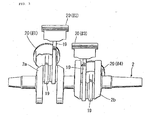
- crankshaft 2 is provided with crankpins 2a, 2b phase shifted over approximately 180 degrees.
- Two connecting rods 19, 19 are supported on the crank pin 2a, and two connecting rods 19, 19 are supported on the crank pin 2b.
- Cylinders with these pistons 20 accommodated therein are arranged as the cylinder #1, cylinder #2, cylinder #3 and cylinder #4 in this order from the left side in FIG. 3 (the left side of a vehicle body).
- the left side and right side of the front bank Bf are, therefore, the cylinder #1 and the cylinder #4, respectively, and the left side and right side of the rear bank Br are, therefore, the cylinder #2 and the cylinder #3, respectively.
- the cylinder #1 and cylinder #4 are ignited at equal intervals, and the cylinder #2 and cylinder #3 are also ignited at equal intervals.
- Each cylinder is provided with two intake valves IV and two exhaust valves EV.
- the cylinder #1 and cylinder #4 are constructed as full-time operating cylinders, while the cylinder #2 and cylinder #3 are constructed as deactivatable cylinders. Therefore, as illustrated in FIG. 1, the engine valves for the cylinder #1 (also for the cylinder #4) consist of two combinations of full-time on/off operating, intake valves IV and exhaust valves EV, and the engine valves for the cylinder #2 (also for the cylinder #3) consist of two combinations of intake valves IV and exhaust valves EV provided with valve-deactivating mechanisms to be described subsequently.
- the cylinder head 6 of the cylinder #2 has a concave part 22, which forms a combustion chamber 21 in combination with the cylinder block 3 and piston 20.
- a concave part 22 In the concave part 22, two intake valve openings 23 and two exhaust valve openings 24 are formed.
- the intake valve openings 23 are opened and closed by the intake valves IV, while the exhaust valve openings 24 are opened and closed by the exhaust valves EV. It is to be noted that the intake valves IV and exhaust valves EV all have a deactivatable construction.
- Each intake valve IV is formed of a valve head 25, which can close its corresponding intake valve opening 23, and a valve stem 26 a basal end of which is arranged integrally and in continuation with the valve head 25.
- Each exhaust valve EV is constructed of a valve head 27, which can close its corresponding exhaust valve opening 24, and a valve stem 28 a basal end of which is arranged integrally and in continuation with the valve head 27.
- valve stem 26 of the intake valve IV is slidably fitted in a guide cylinder 29 arranged in the cylinder head 5.
- the valve stem 28 of the exhaust valve EV is slidably fitted in a guide cylinder 30 arranged in the cylinder head 5.
- a retainer 31 is fixedly secured on a portion of the valve stem 26 for the intake valve IV, the portion extending upwardly from the guide cylinder 29, and by a coil-shaped valve spring 32 arranged between the retainer 31 and the cylinder head 6, the intake valve IV is biased in a direction that the intake valve opening 23 is closed.
- the intake valve IV for each combustion chamber 21 is operated to open and close by the valve actuator 33.
- This valve actuator 33 has a camshaft 35 with a valve cam 34 arranged corresponding to the associated intake valve IV, and is also equipped with a closed-bottom, cylindrical valve lifter 36 slidably driven by the valve cam 34.
- the exhaust valves EV and intake valves IV are all operated to open or close by their corresponding valve actuators 33 of a similar construction.
- Each valve actuator 33 has a camshaft 35, on which a valve cam 34 corresponding to the exhaust valve EV is arranged, and is also provided with a closed-bottom cylindrical valve lifter 36 slidably driven by the valve cam 34.
- the camshaft 35 has an axis line orthogonal to an extension of an axis line of the valve stem 26 of the intake valve IV, and is rotatably supported between the cylinder head 6 and the cylinder head cover 8 connected to the cylinder head 6.
- the valve lifter 36 is slidably fitted in a direction coaxial with the axis line of the valve stem 26 of the intake valve IV, and the valve lifer 36 is in sliding contact on an outer wall of its closed end with the valve cam 34.
- valve deactivating mechanism 37 Arranged between the valve stem 26 of the intake valve IV and the valve lifter 36 is a valve deactivating mechanism 37, which can selectively set an application or non-application of pressing force in a valve-opening direction from the valve lifter 36 to the intake valve IV, and in a particular operation range of the engine 1, for example, in a low load range such as a low-speed operation range, pressing force is controlled in a non-applied state so that the intake valve IV is maintained in a disabled state irrespective a sliding motion of the valve lifter 36.
- the camshaft 35 on the side of the exhaust valve EV also has an axis line orthogonal to an extension of an axis line of the valve stem 28 of the exhaust valve EV, and is rotatably supported between the cylinder head 6 and the cylinder head cover 8 connected to the cylinder head 6.
- the valve lifter 36 is slidably fitted in a direction coaxial with the axis line of the valve stem 28 of the exhaust valve EV, and the valve lifer 36 is in sliding contact on an outer wall of its closed end with the valve cam 34.
- valve deactivating mechanism 37 Arranged between the valve stem 28 of the exhaust valve EV and the valve lifter 36 is a valve deactivating mechanism 37, which can selectively set an application or non-application of pressing force in a valve-opening direction from the valve lifter 36 to the exhaust valve EV, and in a particular operation range of the engine 1, for example, in a low load range such as the low-speed operation range, pressing force is controlled in a non-applied state so that the exhaust valve EV is maintained in a disabled state irrespective a sliding motion of the valve lifter 36.
- valve deactivating mechanism 37 Taking the side of the intake valve IV as an example, a description will next be made about the valve deactivating mechanism 37.
- the valve deactivating mechanism 37 is provided with a pin holder 40, which is fitted in the valve lifter 36 and is slidable in an axial direction. It is to be noted that between the pin holder 40 and the cylinder head 6, a valve spring 38 is arranged to bias the pin holder 40 in an upward direction.
- the pin holder 40 has an insertion hole with the valve stem 26 inserted therethrough and a slide hole orthogonal to the insertion hole. Through the slide hole, a slide pin 41 is slidably inserted.
- the slide pin 41 is biased at an end thereof by a return spring 42, and at an opposite end of the slide pin 41, a hydraulic pressure chamber 43 is formed and the slide pin 41 is maintained in contact with a stopper pin 44 arranged in the hydraulic pressure chamber 43.
- a receiving bore 45 is formed such that it is coaxially in communication with the insert hole of the pin holder 40 in a state that the slide pin 41 is biased by the return spring 42 and is in contact with the stopper pin 44 and in a stopped state.
- an oilway 46 in the cylinder head 6 communicates to the hydraulic pressure chamber 43 in the slide hole of the pin holder 40.
- the slide pin 41 comes into contact with the stopper pin 44 and stops under the biasing force of the return spring 42, so that an upper end portion of the valve stem 26 inserted in the insert hole of the pin holder 40 is in a state ready to be received in the receiving bore 45.
- the valve lifter 36 is pressed downwardly together with the pin holder 40 as a result of a rotation of the valve cam 34, the upper end portion of the valve stem 26 is, therefore, received in the receiving bore 45 so that no pressing force acts on the intake valve IV to maintain it in a disabled state that a valve-closed state is maintained.
- valve deactivating mechanisms 37 similar to those described above are also arranged likewise for the exhaust valves EV. At the time of cylinder deactivation, all the valve deactivating mechanisms 37 operate, and all the four valves, that is, the intake valves IV and exhaust valves EV close the intake manifolds 10 and exhaust manifolds 12. It is to be noted that the cylinder #3 is provided with the same valve deactivating mechanism 37 as the cylinder #2.
- the cylinder #1 and cylinder #4 which constitute the front bank Bf of the engine 1 both become full-time operating cylinders that none of their engine valves are disabled.
- the cylinder #2 and cylinder #3 which constitute the rear bank Br become deactivatable cylinders that the respective valve deactivating mechanisms 37 disable the intake valves IV and exhaust valves EV of the respective cylinders and all the engine valves are hence deactivated to disable the cylinders.
- the respective cylinder heads 5, 6 are provided on their side walls on the sides of the cylinder #4 and cylinder #3 with cam chain cases 50, respectively.
- cam chain cases 50 there are accommodated unillustrated cam chains for driving the camshafts 35, 35 in the intake-side and discharge-side valve actuators 33, 33 respectively.
- hydraulic control valves 51, 51 are mounted to feed working oil under control to the valve deactivating mechanisms 37, 37 in the intake-side and discharge-side valve actuators 33, 33, respectively.
- working oil stored in an oil pan 52 is fed to the hydraulic control valve 51 on the intake side (similarly to the exhaust side too).
- a main oilway 54 with a pump 53 arranged thereon is connected to the oil pan 52, and on a delivery side of the pump 53, a branch channel 55 to be connected to the hydraulic control valves 51, 51 branches out from the main oilway 54.
- the working oil can be recovered into the oil pan 52 from a drain channel 56 via drain ports of the hydraulic control valves 51, 51.
- Control of the hydraulic control valve 51, 51 is performed at ECU 61, which is an electronic control unit, on a basis of a throttle grip opening degree (hand throttle rotation) ⁇ g, an engine speed NE (rpm), a detection signal from a deactivation discriminating magnetic sensor 60, and the like.
- This deactivation discriminating magnetic sensor 60 is a sensor, which detects a distance from the deactivation discriminating magnetic sensor 60 to a wall portion of the slide pin 41, is equipped with a magnet and a coil, and by detecting the distance from a change in magnetic flux that occurs when the metal-made slide pin 41 moves, discriminates whether or not the cylinder is disabled.
- ECU 61 To optimally set a throttle valve opening degree TH on the basis of a detection value from the throttle grip opening degree sensor G or the like, ECU 61 outputs a drive control signal to the corresponding motor 16 to control the throttle valve 14 while detecting the throttle valve opening degree TH by the throttle valve opening degree sensor S. Further, the injection quantity of fuel at the injector 18 is controlled based on a control signal from ECU 61. As described above, ECU 61 is provided with the means for switching the hydraulic control valves 51, 51, the means for controlling throttle valve openings TH and the means for controlling the injection quantities of fuel.
- a approximately 18 degrees
- the routine advances to step S2.
- the routine advances to step S3.
- NE1 7,000 rpm
- the routine advances to step S6, operation is performed in a 2-cylinder/4-valve mode (see FIG. 7 and FIG. 8(a)), and the processing is ended.
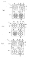
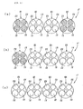
- FIG. 8 hatching indicates engine valves in a disabled state (the same shall apply equally to FIG. 9 and FIG. 10).
- This cylinder deactivation control is used in low-load ranges such as take-off, idling and cruising.
- the motorcycle is ridden by disabling all the engine valves with respect to the cylinder #2 and cylinder #3, which are deactivatable cylinders in the rear bank Br, and operating only the cylinder #1 and cylinder #4 as the full-time operating cylinders in the front bank Bf.
- step S2 When the engine speed NE is equal to or higher than the predetermined value NE1 as a result of the determination in step S2, on the other hand, the routine advances to step S7 to perform operation in a 4-cylinder/4-valve mode (see FIG. 7 and FIG. 8(c)), and the processing is ended.
- ⁇ a predetermined value
- the routine advances to step S4.
- the routine advances to step S7.
- the routine advances to step S5 to perform operation in a 3-cylinder/4-valve mode (see FIG. 7 and FIG. 8(b)), and the processing is ended.
- the routine advances to step S7.
- the operator's intent of an acceleration is not very strong but the running speed is need to be retained at a certain level. Accordingly, one of the deactivatable cylinder is operated and the other deactivatable cylinder is disabled, thereby making it possible to improve the fuel economy and to heighten the commercial value. Described specifically, in the 3-cylinder/4-valve mode, operation is performed with the left-side cylinder #2 in the rear bank Br being disabled and with the cylinder #3 in the rear bank Br being operated.
- step S5 Upon changing to the 3-cylinder/4-valve mode in step S5, the 2-cylinder/4-valve mode in step S6 or the 4-cylinder/4-valve mode in step S7, it is determined whether or nor the preceding mode was the same mode. When it was the same mode, the operation is performed in the same mode. When the preceding mode was different from the current mode, the mode is changed to the current mode after changing processing is gradually performed. Described specifically, when changing to a mode that the number of operating cylinders is decreased, processing is performed to gradually close the throttle valve 14 via the motor 16 for the cylinder to be disabled, and then, the intake and exhaust valves IV, EV are brought into disabled states from operating states, respectively.
- processing is performed to gradually open the throttle valve 14 via the motor 16 for the cylinder to be operated, and then, the intake and exhaust valves IV, EV are brought into operating states from disabled states, respectively.
- the cylinder #1 and cylinder #4 in the front bank Bf are set as full-time operating cylinders that their intake and exhaust valves IV, EV are not disabled
- the cylinder #2 and cylinder #3 in the rear bank Br are set as deactivatable cylinders, and the cylinder #2 and cylinder #3 are disabled
- the four intake and exhaust valves IV, EV for each cylinder are all disabled and there is no mode that the four intake and exhaust valves IV, EV for each cylinder are disabled in part. Accordingly, the control can be simplified, the processing load of ECU 61 can be reduced, and the operation can be promptly switched.
- the cylinder #1 and cylinder #4 which are full-time operation cylinders subjected to large thermal loads, can be arranged on the laterally-opposite end sides in the direction of the crankshaft to effectively cool them by running wind.
- the engine can; therefore, be cooled effectively.
- the cylinder #1 and cylinder #4 By setting the cylinder #1 and cylinder #4, which are located in the front bank Bf and on laterally-opposite end sides, as full-time operating cylinders and setting the cylinder #2 and cylinder #3 in the rear bank Br as deactivatable cylinders, the cylinder #1 and cylinder #4 to which large thermal loads are applied can be effectively cooled by running wind on a more forward side, and therefore, the engine 1 can be effectively cooled.
- this V-type 4-cylinder engine 1 is mounted on the motor cycle exposed to the outside.
- the cylinder #1 and cylinder #4 which are arranged on laterally-opposite end sides of the crankshaft 2 and in the front bank Bf, can hence be effectively cooled by running wind.
- the opening 9 is arranged in the central part of the front bank Bf arranged on the laterally-opposite end sides of the crankshaft 2, in other words, between the cylinder #1 and the cylinder #4. Accordingly, running wind is allowed to flow rearwards from the opening 9, and the running wind is also allowed to flow to the cylinder #2 and cylinder #3 in the rear bank Br located rearward. It is, therefore, possible to cool the engine 1 still more effectively.
- the pattern of the number of operating cylinders is limited to the three kinds as shown in FIG. 8 and does not adopt, for example, such a pattern that in the deactivatable cylinders, some of the intake and exhaust valves IV, EV are disabled.
- the control can, therefore, be simplified. Accordingly, operation can be promptly switched to each of the modes. By gradually effecting a change upon changing operation of each mode, variations in the output of the engine 1 can be reduced to permit a smooth change.
- FIG. 9 A second embodiment of the present invention will next be described based on FIG. 9 while also making reference to FIG. 1.
- this second embodiment is also directed to a V-type 4-cylinder engine 1' provided with cylinder heads 5, 6 with intake and exhaust vales IV, EV arranged therein, valve actuators 33 for openably operating the intake and exhaust valves IV, EV, respectively, and cylinder head covers 7, 8 forming, in combination with the cylinder heads 5, 6, a valve actuator chamber with the valve actuators 33 accommodated therein, at least some of the valve actuators 33 being deactivatable to disable their corresponding cylinders.
- the V-type 4-cylinder engine 1' is provided with a front bank Bf and rear bank Br. The cylinders on opposite ends in a direction of a crankshaft 2 are set as the deactivatable cylinders in the front bank Bf, and full-time operating cylinders are set in the rear bank Br.
- the cylinder #1 and cylinder #4 are arranged in the front bank Bf, while the cylinder #2 and cylinder #3 are arranged in the rear bank Br.
- the cylinder #1 and cylinder #4 in the front bank Bf are deactivatable cylinders, and the cylinder #2 and cylinder #3 in the rear bank Br are set as full-time operating cylinders.
- Each cylinder is of the 4-valve type that the intake valves IV and exhaust valves EV are arranged in two combinations.
- the cylinder #1 and cylinder #4 as deactivatable cylinders are provided with valve deactivating mechanisms 37, but the cylinder #2 and cylinder #3 as full-time operating cylinders are provided with no valve deactivating mechanisms 37.
- the cylinder #1 and cylinder #4 which are provided with the valve deactivating mechanisms 37, are provided with two operation modes, one being that all the intake and exhaust valves IV, EV of both of the cylinders are disabled, and the other that all the intake and exhaust valves IV, EV of both of the cylinders operate.
- the pattern of the number of operating cylinders is limited to three kinds as depicted in FIG. 9. Specifically, they are a 2-cylinder/4-valve mode (see FIG. 9(a)), 3-cylinder/4-valve mode (see FIG. 9(b)), and 4-cylinder/4-valve mode (see FIG. 9(c)).
- the pattern of the number of operating cylinders does not adopt, for example, such a pattern that in the deactivatable cylinders, some of the intake and exhaust valves IV, EV are disabled.
- the control can, therefore, be simplified. Accordingly, the operation can be promptly switched to each mode.
- the 3-cylinder/4-valve mode means operation that the cylinder #2 on the left side of the front bank Bf is disabled and the cylinder #3 in the front bank Bf is operated, the 2-cylinder/4-valve mode means operation that the cylinder #1 and cylinder #4 in the front bank Bf are disabled, and the 4-cylinder/4-valve mode means operation that the cylinder #1 and cylinder #4 in the front bank Bf are operated. It is to be noted that a description about switching control is omitted because including the gradual changing processing upon changing the number of cylinders, the switching control is similar to that of the first embodiment.
- the full-time operating cylinders that their intake and exhaust valves IV, EV are not disabled are arranged.
- the valve actuators 33 are disabled to deactivate all the intake and exhaust valves IV, EV and hence to disable the cylinders. It is, therefore, possible to bring about advantageous effects that the control can be simplified.
- the cylinders which are arranged closer to an inner side of the engine 1' (the crankshaft 2), as full-time operating cylinders, vibrations can be kept low even when one of the opposite end cylinders in the front bank is disabled. It is, therefore, possible to bring about an advantage that the commercial value can be heightened.
- the arrangement of the opening 9 in the front bank Bf as in the first embodiment makes it possible to also feed cooling wind to the rear bank Br. It is, therefore, possible to reduce thermal loads on the full-time operating cylinders while keeping vibrations low.
- This embodiment is also advantageous in that, when the front bank Bf is provided with the opening 9 as in the first embodiment, running wind is allowed to flow from the opening 9 to the full-time operating cylinders located in the rear bank Br and to cool the rear bank Br.
- FIG. 10 A third embodiment of the present invention will next be described base on FIG. 10 to FIG. 12.
- a conventionally-known inline 4-cylinder engine is referred to as an example of an inline internal combustion engine.
- the construction of basic parts around the cylinders will be described by making reference to the section of the cylinder head 6 in the rear bank Br in FIG. 4 directed to the first embodiment.
- An inline 4-cylinder engine 1" is provided with a cylinder head 6 with intake and exhaust vales IV, EV arranged therein, valve actuators 33 for openably operating the intake and exhaust valves IV, EV, respectively, and a cylinder head cover 7 forming, in combination with the cylinder head 6, a valve actuator chamber with the valve actuators 33 accommodated therein, and at least some of the valve actuators 33 are deactivatable to disable their corresponding cylinders.
- the cylinder #1, the cylinder #2, the cylinder #3 and the cylinder #4 are tandemly arranged from the left side.
- the cylinder #2 and cylinder #3, the two cylinders at the central part in the direction of the length of the crankshaft 2, are constructed as full-time operating cylinders which are phase shifted over 360 degrees and are fired at equal intervals, while the cylinder #1 and cylinder #4, the cylinders on the opposite end sides of the crankshaft 2, are constructed as deactivatable cylinders, respectively.
- the intake and exhaust valves IV, EV arranged for the cylinders #1 and #4 are provided with the valve deactivating mechanisms 37, respectively, and by the valve deactivating mechanisms 37, the intake and exhaust valves IV, EV for the cylinders #1 and #4 can all be disabled.
- the cylinders #1 and #2 are arranged at positions phase shifted over 180 degrees, and so the cylinders #3 and #4.
- an operation mode in which one of the deactivatable cylinders on the opposite end sides of the crankshaft 2, specifically the cylinder #1 is disabled see FIG. 10(a)
- another operation mode in which both of the deactivatable cylinders, specifically the cylinder #1 and #4 are disabled see FIG. 10(b)
- another operation mode in which both of the deactivatable cylinders, specifically the cylinder #1 and #4 are operated see FIG. 10(c)
- upwardly-extending intake manifolds 10 are arranged corresponding to the respective cylinders, that is, the cylinder #1, cylinder #2, cylinder #3 and cylinder #4, and throttle bodies 11 equipped with throttle valves 14 are attached to the respective intake manifolds 10.
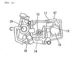
- the throttle valves 14, 14 for the cylinder #2 and cylinder #3 are opened and closed by a common shaft 150, and to the shaft 150, a motor 16 for driving the same is connected via a speed reduction mechanism 17 on a forward side of the throttle body 11. Accordingly, the throttle valves 14 for the cylinder #2 and cylinder #3 are simultaneously operated to open and close by the single motor 16. Further, an opening degree of each of the throttle valves 14, 14 is detected by a throttle valve opening degree sensor S arranged on the shaft 150. To shafts 15, 15 of the respective throttle valves 14, 14 for the cylinder #1 and cylinder #4, on.the other hand, motors 16, 16 are connected via speed reduction mechanism 17, 17, respectively, and an opening degree of each throttle valve 14 is detected by a throttle valve opening degree sensor S arranged for the throttle valve 14.
- injectors 18 are obliquely inserted and fixed toward cylinder heads 5 to inject fuel into the intake manifolds 10.
- Each motor 16 and its corresponding injector 18 are, therefore, arranged such that they are located apart forward and backward of the corresponding throttle body 11 and in the forward and rearward directions of the engine and a vehicle body, respectively.
- fuel pipes 39 are connected to the injectors 18, respectively.
- Connectors 47 are arranged on upper parts of casings 48 for the respective motors 16 and speed reduction mechanisms 17, and the connectors 47 are connected to the above-mentioned ECU 61.
- the cylinder #2 and cylinder #3 are set as full-time operating cylinders that their intake and exhaust valves IV, EV are not disabled, and in one cylinder, its intake and exhaust valves IV, EV are all disabled to deactivate the cylinder. It is, therefore, possible to simplify the control and to promptly switch the operation.
- the cylinder #2 and cylinder #3, the two cylinders in the central part in the direction of the length of the crankshaft 2, are arranged as full-time operating cylinders, and these cylinder #2 and cylinder #3 are fired at equal intervals. Vibrations can, therefore, be maintained low even in the operation mode that one (the cylinder #1) of the deactivatable cylinders on the opposite end sides of the crankshaft 2 is disabled, thereby making it possible to heighten the commercial value.
- the present invention is not limited to the above-described embodiments and can also be applied, for example, to V-type 5-cylinder engines, V-type 6-cylinder engines and inline 6-cylinder engines. Further, the present invention can also be applied to multicylinder engines for 4-wheeled vehicles although it has been described taking motorcycles as
- the invention is directed to a multicylinder internal combustion engine, which can simplify its control and is advantageous against thermal loads or vibrations.
- a multicylinder internal combustion engine including: a cylinder head 5, 6 with intake valves IV and exhaust valves EV arranged therein; valve actuators for openably operating the intake valves IV and exhaust valves EV, respectively; and a cylinder head cover 7, 8 forming, in combination with the cylinder head 5, 6, a valve actuator chamber with the valve actuators accommodated therein, at least some of the valve actuators being deactivatable to disable their corresponding cylinders; wherein the multicylinder internal combustion engine is a V-shaped internal combustion engine provided with a front bank Bf and rear bank Br, and the cylinders on opposite ends in a direction of a crankshaft 2 are set as full-time operating cylinders.
Landscapes
- Engineering & Computer Science (AREA)
- Mechanical Engineering (AREA)
- General Engineering & Computer Science (AREA)
- Chemical & Material Sciences (AREA)
- Combustion & Propulsion (AREA)
- Output Control And Ontrol Of Special Type Engine (AREA)
- Valve Device For Special Equipments (AREA)
Abstract
Description
- This invention relates to a multicylinder internal combustion engine, especially to a cylinder-deactivatable, multicylinder internal combustion engine.
- For example, inline 4-cylinder engines include those capable of deactivating four engine valves, which each cylinder is provided with, selectively in combinations of one intake and exhaust valves and the other intake and exhaust valves. By providing an engine with a function that can selectively deactivate engine valves as mentioned above, the operation of the engine can be controlled in four patterns consisting in combination of a case that the intake and exhaust valve combinations are both closed, cases that the one intake and exhaust valve combination is closed and the other intake and exhaust valve combination is closed, respectively, and a case that the intake and exhaust valve combinations are both operated, all for each cylinder (see patent
document No. JP-A-2004-293379 - The above-described conventional 4-cylinder engine is, however, accompanied by a problem in that its control becomes complex, because the four patterns of cylinder operation state exist and the deactivation state of the intake and exhaust valves in each cylinder exists in two patterns, one being the case that all of the intake and exhaust valves are disabled, and the other the case that some of the intake and exhaust valves are disabled.
- An object of the present invention is, therefore, to provide a multicylinder internal combustion engine, which can simplify its control and is advantageous against thermal loads or vibrations.
- To achieve the above-described object, the invention described in
claim 1 is characterized in that, in a multicylinder internal combustion engine provided with a cylinder head (for example,cylinder heads valve actuators 33 according to an embodiment) for openably operating the engine valves, respectively, and a cylinder head cover (for example, cylinder head covers 7, 8 according to an embodiment) forming, in combination with the cylinder head, a valve actuator chamber with the valve actuators accommodated therein, at least some of the valve actuators being deactivatable to disable their corresponding cylinders, the internal combustion engine is a V-shaped internal combustion engine provided with a front bank (for example, a front bank Bf in the embodiment) and rear bank (for example, a rear bank Br according to an embodiment), and the cylinders (for example, thecylinder # 1 andcylinder # 4 according to an embodiment) on opposite ends in a direction of a crankshaft (for example, acrankshaft 2 according to an embodiment) are set as full-time operating cylinders. - Owing to the construction as described above, the full-time operating cylinders that their valves are not disabled are arranged. By disabling the valve actuators to deactivate all the engine valves, the cylinders are disabled so that the control can be simplified. Further, the full-time operating cylinders to which large thermal loads are applied are arranged on the laterally opposite end sides in the direction of the crankshaft, where the cylinders are readily exposed to running wind, so that the full-time operating cylinders can be effectively cooled by running wind.
- The invention described in
claim 2 is characterized in that the cylinders located at laterally opposite ends in the front bank are set as full-time operating cylinders, and the cylinders in the rear bank (for example, thecylinder # 2 andcylinder # 3 in the embodiment) are set as deactivatable cylinders. - Owing to the construction as described above, the full-time operating cylinders to which large thermal loads are applied can be effectively cooled by running wind in the more forward side.
- The invention described in
claim 3 is characterized in that the V-type internal combustion engine is to be mounted on a motorcycle. - Owing to the construction as described above, the full-time operating cylinders on the opposite end sides of the crankshaft or on the side of the front bank, said full-time operating cylinders being exposed to large thermal loads, can be effectively cooled by running wind in the motorcycle in which the internal combustion engine is exposed to the outside.
- When the cylinders in the front bank are arranged on the opposite end sides of the crankshaft, running wind can be made flowable rearwards from a central part of the front bank so that the running wind is also allowed to flow to the cylinders in the rear bank located rearward.
- The invention described in
claim 4 is characterized in that, in a multicylinder internal combustion engine provided with a cylinder head with engine valves arranged therein, valve actuators for openably operating the engine valves, respectively, and a cylinder head cover forming, in combination with the cylinder head, a valve actuator chamber with the valve actuators accommodated therein, at least some of the valve actuators being deactivatable to disable their corresponding cylinders, the internal combustion engine is a V-shaped internal combustion engine provided with a front bank and rear bank, the cylinders on opposite ends in a direction of a crankshaft in the front bank (for example, thecylinder # 1 andcylinder # 4 according to an embodiment) are set as the deactivatable cylinders, and the cylinders in the rear bank (for example, thecylinder # 2 andcylinder # 3 according to an embodiment) are set as full-time operating cylinders. - Owing to the construction as described above, the full-time operating cylinders that their valves are not disabled are arranged. By disabling the valve actuators to deactivate all the engine valves, the cylinders are disabled so that their control can be simplified. By setting as full-time operating cylinders the cylinders arranged closer to an inner side of the crankshaft, vibrations can be kept low even when one of the opposite end cylinders in the front bank is disabled.
- The invention described in
claim 5 is characterized in that the internal combustion engine is a V-shaped 4-cylinder internal combustion engine, and a number of operating cylinders is selectively changeable in three patterns. - Owing to the construction as described above, the number of operating cylinders is limited to three patterns so that the control can be simplified.
- The invention described in
claim 6 is characterized in that, in a multicylinder internal combustion engine provided with a cylinder head (for example, thecylinder head 6 according to an embodiment) with engine valves (for example, intake valves IV and exhaust valves EV according to an embodiment) arranged therein, valve actuators (for example,valve actuators 33 according to an embodiment) for openably operating the engine valves, respectively, and a cylinder head cover (for example, thecylinder head cover 8 according to an embodiment) forming, in combination with the cylinder head, a valve actuator chamber with the valve actuators accommodated therein, at least some of the valve actuators being deactivatable to disable their corresponding cylinders, the internal combustion engine is an inline internal combustion engine, the two cylinders (for example, thecylinder # 2 and cylinder #3) at a central part in a longitudinal direction of a crankshaft (for example, acrankshaft 2 according to an embodiment) are constructed as full-time operating cylinders that are fired at equal intervals, the cylinders (for example, thecylinder # 1 andcylinder # 4 according to an embodiment) on opposite end sides of the crankshaft are constructed as deactivatable cylinders, respectively, and an operation mode of the inline internal combustion engine is selectively changeable to one of operation modes consisting of an operation mode in which one of the deactivatable cylinders on the opposite end sides of the crankshaft is disabled, another operation mode in which both of the deactivatable cylinders are disabled, and a further operation mode in which both of the deactivatable cylinders are operated. - Owing to the construction as described above, the full-time operating cylinders that their valves are not disabled are arranged. By disabling the valve actuators to deactivate all the engine valves, the cylinders are disabled so that their control can be simplified. As the two cylinders at the central part in the longitudinal direction of the crankshaft are constructed as full-time operating cylinders and are set to are fired at equal intervals, vibrations can be kept low even when one of the cylinders on the opposite end sides of the crankshaft is disabled.
- The invention described in
claim 7 is characterized in that the internal combustion engine is an inline 4-cylinder internal combustion engine. - Owing to the construction as described above, the two cylinders at the central part are constructed as full-time operating cylinders and are set to are fired at equal intervals. Vibrations can be kept low even when one of the deactivatable cylinders on the opposite end sides is disabled.
- The invention described in
claim 8 is characterized in that the deactivatable cylinders are the cylinders located on the opposite end sides of the crankshaft. - Owing to the construction as described above, the cylinders located on the opposite end sides of the crankshaft are set as deactivatable cylinders by adopting the vibrationally-balanced arrangement that firing is performed at equal intervals in the central part.
- According to the invention described in
claim 1, the full-time operating cylinders that their valves are not disabled are arranged. By disabling the valve actuators to deactivate all the engine valves, the cylinders are disabled. It is, therefore, possible to bring about advantageous effects that the control can be simplified and the operation can be promptly switched. Further, the full-time operating cylinders to which large thermal loads are applied are arranged on the laterally opposite end sides in the direction of the crankshaft and therefore, can be effectively cooled by running wind. It is, hence, possible to bring above a further advantageous effect that the engine can be effectively cooled. - According to the invention described in
claim 2, the full-time operating cylinders to which large thermal loads are applied can be effectively cooled on the more front side. It is, therefore, possible to bring about an advantageous effect that the engine can be effectively cooled. - According to the invention described in
claim 3, in the motorcycle with the internal combustion engine exposed to the outside, the full-time operating cylinders on the opposite end sides of the crankshaft or on the side of the front bank, said full-time operating cylinders being subjected to large thermal loads, can be effectively cooled by running wind. It is, therefore, possible to bring about an advantageous effect that the engine can be effectively cooled. - Further, when the cylinders in the front bank are arranged on the opposite end sides of the crankshaft, running wind is also allowed to flow to the cylinders in the rear bank located rearward by designing such that the running wind flows rearward through the central part of the front bank. The engine can, therefore, be cooled still more effectively.
- According to the invention described in
claim 4, the full-time operating cylinders that their valves are not disabled are arranged. The valve actuators are disabled to deactivate all the engine valves. It is, therefore, possible to bring about advantageous effects that the control can be simplified and the operation can be promptly switched. By arranging the cylinders, which are arranged closer to an inner side of the crankshaft, as full-time operating cylinders in the rear bank, vibrations can be kept low even when one of the opposite end cylinders in the front bank is disabled. It is, therefore, possible to bring about an advantage that the commercial value can be heightened. - According to the invention described in
claim 5, the number of operating cylinders is limited to three patterns so that the control can be simplified. It is, therefore, possible to bring about an advantageous effect that the operation can be promptly switched. - According to the invention described in
claim 6, the full-time operating cylinders that their valves are not disabled are arranged. By disabling the valve actuators to deactivate all the engine valves, the cylinders are disabled. It is, therefore, possible to bring about advantageous effects that the control can be simplified and the operation can be promptly switched. - Further, the two cylinders in the central part in the longitudinal direction of the crankshaft are set as full-time operating cylinders and are constructed to are fired at equal intervals. Vibrations can, therefore, be kept low even when one of the deactivatable cylinders on the opposite end sides of the crankshaft is disabled. It is, therefore, possible to bring about an advantage that the commercial value can be heightened.
- According to the invention described in
claim 7, the two cylinders in the central part are set as full-time operating cylinders and are constructed to are fired at equal intervals. Vibrations can, therefore, be kept low even when one of the deactivatable cylinders on the opposite end sides is disabled. It is, therefore, possible to bring about an advantage that the commercial value can be heightened. - According to the invention described in
claim 8, the cylinders located on the opposite end sides of the crankshaft are set as deactivatable cylinders by adopting the vibrationally-balanced arrangement that firing is performed at equal intervals in the central part. It is, therefore, possible to bring about an advantage that the commercial value can be heightened. -
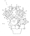
- Fig. 1: A side view of a V-type 4-cylinder engine according to an embodiment of the present invention.
- Fig. 2: A schematic plan view of the embodiment of the present invention.
- Fig. 3: A side view of a crankshaft in the embodiment of the present invention.
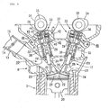
- Fig. 4: A side view of a cylinder head in the embodiment of the present invention.
- Fig. 5: A system diagram of the embodiment of the present invention.
- Fig. 6: A flow diagram of the embodiment of the present invention.
- Fig. 7: A graphic diagram of the embodiment of the-present invention.
- Fig. 8: Plan views schematically illustrating operation modes of the embodiment of the present invention.
- Fig. 9: Plan views schematically illustrating operation modes of a second embodiment of the present invention.
- Fig. 10: Plan views schematically illustrating operation modes of a third embodiment of the present invention.
- Fig. 11: A plan view of throttle bodies in the third embodiment of the present invention.
- Fig. 12: A plan view of one of the throttle bodies in the third embodiment of the present invention.
- Embodiments of the present invention will next be described based on drawings.
- As illustrated in FIG. 1 and FIG. 2, a four-stroke
cycle DOHC engine 1 to be mounted on a motorcycle (not shown) is a laterally-mounted, V-type 4-cylinder engine that acrankshaft 2 is arranged along a lateral direction and a front bank Bf, which is a train of two cylinders on a front side, and a rear bank Bf, which is a train of two cylinders on a rear side, define a contained angle of approximately 72 degrees in a front-to-rear direction. It is to be noted that sign Fr indicates a forward side of the vehicle. Each cylinder is equipped with two intake valves IV and two exhaust valves EV to be described subsequently herein. Theengine 1 is provided with acylinder block 3, acrankcase 4 mounted integrally on a lower wall of thecylinder block 3, acylinder head 5 mounted on an upper part of the cylinder train on the front side of thecylinder block 3, acylinder head 6 mounted on an upper part of the cylinder train on the rear side of the cylinder block, and cylinder head covers 7, 8 covering thesecylinder heads respective cylinder heads cylinder heads valve actuators 33 to be described subsequently herein. Anopening 9 is formed through the front bank Bf at a central part thereof in the direction of the crankshaft, so that by allowing air to enter through theopening 9, running wind flows toward the rear bank Br. - On a rear part of the front bank Bf, upwardly-extending
intake manifolds 10 are arranged corresponding to the respective cylinders, andthrottle bodies 11 are attached to therespective intake manifolds 10. On a front part of the rear bank Br, upwardly-extendingintake manifolds 10 are also arranged corresponding to therespective intake manifolds 10, andthrottle bodies 13 are attached to therespective intake manifolds 10. - Within the
respective throttle bodies butterfly throttle valves 14 are arranged openably and closably. Toexhaust manifolds 12 of therespective cylinder heads throttle valve 14 is of the so-called electronic throttle control type that in accordance with a throttle grip opening degree θg (degrees), in other words, an acceleration intent or the like of the operator, it is operated to open or close in association with a motor. In addition, a throttle valve opening sensor S which detects a throttle valve opening degree TH is arranged in association with eachthrottle valve 14 to permit detection of an accurate rotation angle of thethrottle valve 14 driven by the motor (see FIG. 5). - To
shafts respective throttle valves motor 16, provided between theshafts speed reduction mechanism 17 to drive both of theshafts respective throttle valves 14 are simultaneously operated to open or close by thesingle motor 16. Further, opening degrees of both of thethrottle valves shaft 15. - To
shafts respective throttle valves motors speed reduction mechanisms individual throttle valves 14 are detected by throttle valve opening degree sensors S arranged for therespective throttle valves 14. In rear walls of therespective throttle bodies 11 in the front bank Bf,injectors 18 are obliquely inserted and fixed toward thecylinder heads 5 to inject fuel into theintake manifolds 10. In front walls of therespective throttle bodies 13 in the rear bank Br,injectors 18 of similar construction are also inserted and fixed obliquely toward thecylinder heads 6. - As depicted in FIG. 3, the
crankshaft 2 is provided withcrankpins rods crank pin 2a, and two connectingrods crank pin 2b. Cylinders with thesepistons 20 accommodated therein are arranged as thecylinder # 1,cylinder # 2,cylinder # 3 andcylinder # 4 in this order from the left side in FIG. 3 (the left side of a vehicle body). In this V-type 4-cylinder engine, the left side and right side of the front bank Bf are, therefore, thecylinder # 1 and thecylinder # 4, respectively, and the left side and right side of the rear bank Br are, therefore, thecylinder # 2 and thecylinder # 3, respectively. - A description will next be made about the firing order of the cylinders when all the cylinders are operated. When the
cylinder # 1 is fired in the front bank Bf, thecylinder # 3 is fired 104 degrees after that, thecylinder # 4 is then fired 256 degrees after, the #2 cylinder is finally fired 104 degrees after, and 256 degrees after, thecylinder # 1 is fired again. - Accordingly, the
cylinder # 1 andcylinder # 4 are ignited at equal intervals, and thecylinder # 2 andcylinder # 3 are also ignited at equal intervals. - Each cylinder is provided with two intake valves IV and two exhaust valves EV. The
cylinder # 1 andcylinder # 4 are constructed as full-time operating cylinders, while thecylinder # 2 andcylinder # 3 are constructed as deactivatable cylinders. Therefore, as illustrated in FIG. 1, the engine valves for the cylinder #1 (also for the cylinder #4) consist of two combinations of full-time on/off operating, intake valves IV and exhaust valves EV, and the engine valves for the cylinder #2 (also for the cylinder #3) consist of two combinations of intake valves IV and exhaust valves EV provided with valve-deactivating mechanisms to be described subsequently. - A description will hereinafter be made taking as an example the
cylinder # 2 equipped with a valve-deactivating mechanism. It is to be noted that the description will be made centering around the intake valve IV and exhaust valve EV arranged on a diagonal line of thecylinder # 2. Accordingly, a description about the intake valve IV and exhaust valve EV of similar constructions arranged on the other diagonal line is omitted. A description about thecylinder # 1 andcylinder # 4, which are ordinary cylinders equipped with the intake valves IV and exhaust valves EV provided with no valve-deactivating mechanisms, is also omitted. - The
cylinder head 6 of thecylinder # 2 has aconcave part 22, which forms acombustion chamber 21 in combination with thecylinder block 3 andpiston 20. In theconcave part 22, twointake valve openings 23 and twoexhaust valve openings 24 are formed. Theintake valve openings 23 are opened and closed by the intake valves IV, while theexhaust valve openings 24 are opened and closed by the exhaust valves EV. It is to be noted that the intake valves IV and exhaust valves EV all have a deactivatable construction. - Each intake valve IV is formed of a
valve head 25, which can close its correspondingintake valve opening 23, and a valve stem 26 a basal end of which is arranged integrally and in continuation with thevalve head 25. Each exhaust valve EV is constructed of avalve head 27, which can close its correspondingexhaust valve opening 24, and a valve stem 28 a basal end of which is arranged integrally and in continuation with thevalve head 27. - The valve stem 26 of the intake valve IV is slidably fitted in a
guide cylinder 29 arranged in thecylinder head 5. The valve stem 28 of the exhaust valve EV is slidably fitted in aguide cylinder 30 arranged in thecylinder head 5. - A
retainer 31 is fixedly secured on a portion of thevalve stem 26 for the intake valve IV, the portion extending upwardly from theguide cylinder 29, and by a coil-shapedvalve spring 32 arranged between theretainer 31 and thecylinder head 6, the intake valve IV is biased in a direction that theintake valve opening 23 is closed. - Similarly, by a coil-shaped
valve spring 32 arranged between aretainer 31 fixedly secured on thevalve stem 28 for the exhaust valve EV and thecylinder head 6, the exhaust valve EV is biased in a direction that the exhaust valve opening 24 is closed. - The intake valve IV for each
combustion chamber 21 is operated to open and close by thevalve actuator 33. This valve actuator 33 has acamshaft 35 with avalve cam 34 arranged corresponding to the associated intake valve IV, and is also equipped with a closed-bottom,cylindrical valve lifter 36 slidably driven by thevalve cam 34. The exhaust valves EV and intake valves IV are all operated to open or close by theircorresponding valve actuators 33 of a similar construction. Eachvalve actuator 33 has acamshaft 35, on which avalve cam 34 corresponding to the exhaust valve EV is arranged, and is also provided with a closed-bottomcylindrical valve lifter 36 slidably driven by thevalve cam 34. - The
camshaft 35 has an axis line orthogonal to an extension of an axis line of thevalve stem 26 of the intake valve IV, and is rotatably supported between thecylinder head 6 and thecylinder head cover 8 connected to thecylinder head 6. In thecylinder head 6, thevalve lifter 36 is slidably fitted in a direction coaxial with the axis line of thevalve stem 26 of the intake valve IV, and thevalve lifer 36 is in sliding contact on an outer wall of its closed end with thevalve cam 34. - Arranged between the
valve stem 26 of the intake valve IV and thevalve lifter 36 is avalve deactivating mechanism 37, which can selectively set an application or non-application of pressing force in a valve-opening direction from thevalve lifter 36 to the intake valve IV, and in a particular operation range of theengine 1, for example, in a low load range such as a low-speed operation range, pressing force is controlled in a non-applied state so that the intake valve IV is maintained in a disabled state irrespective a sliding motion of thevalve lifter 36. - Similar to the
camshaft 35 on the side of the intake valve IV, thecamshaft 35 on the side of the exhaust valve EV also has an axis line orthogonal to an extension of an axis line of thevalve stem 28 of the exhaust valve EV, and is rotatably supported between thecylinder head 6 and thecylinder head cover 8 connected to thecylinder head 6. In thecylinder head 6, thevalve lifter 36 is slidably fitted in a direction coaxial with the axis line of thevalve stem 28 of the exhaust valve EV, and thevalve lifer 36 is in sliding contact on an outer wall of its closed end with thevalve cam 34. - Arranged between the
valve stem 28 of the exhaust valve EV and thevalve lifter 36 is avalve deactivating mechanism 37, which can selectively set an application or non-application of pressing force in a valve-opening direction from thevalve lifter 36 to the exhaust valve EV, and in a particular operation range of theengine 1, for example, in a low load range such as the low-speed operation range, pressing force is controlled in a non-applied state so that the exhaust valve EV is maintained in a disabled state irrespective a sliding motion of thevalve lifter 36. - Taking the side of the intake valve IV as an example, a description will next be made about the
valve deactivating mechanism 37. - The
valve deactivating mechanism 37 is provided with apin holder 40, which is fitted in thevalve lifter 36 and is slidable in an axial direction. It is to be noted that between thepin holder 40 and thecylinder head 6, avalve spring 38 is arranged to bias thepin holder 40 in an upward direction. Thepin holder 40 has an insertion hole with thevalve stem 26 inserted therethrough and a slide hole orthogonal to the insertion hole. Through the slide hole, aslide pin 41 is slidably inserted. Theslide pin 41 is biased at an end thereof by areturn spring 42, and at an opposite end of theslide pin 41, ahydraulic pressure chamber 43 is formed and theslide pin 41 is maintained in contact with astopper pin 44 arranged in thehydraulic pressure chamber 43. - Through the
slide pin 41, a receivingbore 45 is formed such that it is coaxially in communication with the insert hole of thepin holder 40 in a state that theslide pin 41 is biased by thereturn spring 42 and is in contact with thestopper pin 44 and in a stopped state. To thehydraulic pressure chamber 43 in the slide hole of thepin holder 40, anoilway 46 in thecylinder head 6 communicates. - At the time of non-operation that the hydraulic pressure acting on the
slide pin 41 is low, theslide pin 41 comes into contact with thestopper pin 44 and stops under the biasing force of thereturn spring 42, so that an upper end portion of thevalve stem 26 inserted in the insert hole of thepin holder 40 is in a state ready to be received in the receiving bore 45. Even when thevalve lifter 36 is pressed downwardly together with thepin holder 40 as a result of a rotation of thevalve cam 34, the upper end portion of thevalve stem 26 is, therefore, received in the receiving bore 45 so that no pressing force acts on the intake valve IV to maintain it in a disabled state that a valve-closed state is maintained. - At the time of operation that the hydraulic pressure acting on the
slide pin 41 is high, on the other hand, theslide pin 41 slides against the biasing force of thereturn spring 42 under the pressure oil and closes the opening of the insert hole of thepin holder 40. The upper end portion of thevalve stem 26 inserted in the insert hole, therefore, comes into contact with theslide pin 41. When thevalve lifter 36 is pressed downwardly together with thepin holder 40 as a result of a rotation of thevalve cam 34, pressing force, hence, acts on the intake valve IV via theslide pin 41 to open theintake manifold 10, and the intake valve IV is operated on and off in accordance with reciprocations of thevalve lifter 36. - Other
valve deactivating mechanisms 37 similar to those described above are also arranged likewise for the exhaust valves EV. At the time of cylinder deactivation, all thevalve deactivating mechanisms 37 operate, and all the four valves, that is, the intake valves IV and exhaust valves EV close theintake manifolds 10 and exhaust manifolds 12. It is to be noted that thecylinder # 3 is provided with the samevalve deactivating mechanism 37 as thecylinder # 2. - Upon disabling any cylinder by its corresponding
valve deactivating mechanism 37, there is performed so-called "fuel cutoff" that the feeding of fuel from theinjector 18 is stopped, and thethrottle valve 14 is brought into a fully-closed position via themotor 16 andspeed reduction mechanism 17. - Therefore, the
cylinder # 1 andcylinder # 4 which constitute the front bank Bf of theengine 1 both become full-time operating cylinders that none of their engine valves are disabled. On the other hand, thecylinder # 2 andcylinder # 3 which constitute the rear bank Br become deactivatable cylinders that the respectivevalve deactivating mechanisms 37 disable the intake valves IV and exhaust valves EV of the respective cylinders and all the engine valves are hence deactivated to disable the cylinders. - As depicted in FIG. 2, the
respective cylinder heads cylinder # 4 andcylinder # 3 withcam chain cases 50, respectively. Within thesecam chain cases 50, there are accommodated unillustrated cam chains for driving thecamshafts side valve actuators cylinder head cover 8 in the rear bank Br,hydraulic control valves valve deactivating mechanisms side valve actuators - As shown in FIG. 5 by taking the intake side as an example, working oil stored in an
oil pan 52 is fed to thehydraulic control valve 51 on the intake side (similarly to the exhaust side too). Amain oilway 54 with apump 53 arranged thereon is connected to theoil pan 52, and on a delivery side of thepump 53, abranch channel 55 to be connected to thehydraulic control valves main oilway 54. Further, the working oil can be recovered into theoil pan 52 from adrain channel 56 via drain ports of thehydraulic control valves - Control of the
hydraulic control valve ECU 61, which is an electronic control unit, on a basis of a throttle grip opening degree (hand throttle rotation) θg, an engine speed NE (rpm), a detection signal from a deactivation discriminatingmagnetic sensor 60, and the like. This deactivation discriminatingmagnetic sensor 60 is a sensor, which detects a distance from the deactivation discriminatingmagnetic sensor 60 to a wall portion of theslide pin 41, is equipped with a magnet and a coil, and by detecting the distance from a change in magnetic flux that occurs when the metal-madeslide pin 41 moves, discriminates whether or not the cylinder is disabled. - To optimally set a throttle valve opening degree TH on the basis of a detection value from the throttle grip opening degree sensor G or the like,
ECU 61 outputs a drive control signal to thecorresponding motor 16 to control thethrottle valve 14 while detecting the throttle valve opening degree TH by the throttle valve opening degree sensor S. Further, the injection quantity of fuel at theinjector 18 is controlled based on a control signal fromECU 61. As described above,ECU 61 is provided with the means for switching thehydraulic control valves - Based on a flow chart of FIG. 6, a description will next be made about cylinder deactivation control performed by
ECU 61. - Firstly, it is determined in step S1 whether or not a throttle grip opening degree θg detected based on a detection signal from the throttle grip opening degree sensor G is smaller than a predetermined value α (a = approximately 18 degrees). When the throttle grip opening degree θg is smaller than the predetermined value a as a result of the determination in step S1, the routine advances to step S2. When the throttle grip opening degree θg is equal to or greater than predetermined value a, on the other hand, the routine advances to step S3.
- In step S2, it is determined whether or not an engine speed NE is lower than a predetermined value NE1 (NE1 = 7,000 rpm). When the engine speed NE is lower than the predetermined value NE1 as a result of the determination in step S2, the routine advances to step S6, operation is performed in a 2-cylinder/4-valve mode (see FIG. 7 and FIG. 8(a)), and the processing is ended. It is to be noted that in FIG. 8, hatching indicates engine valves in a disabled state (the same shall apply equally to FIG. 9 and FIG. 10). This cylinder deactivation control is used in low-load ranges such as take-off, idling and cruising.
- Namely, when the throttle grip opening degree θg representing the operator's intent of an acceleration is small and the engine speed NE is also small, the motorcycle is ridden by disabling all the engine valves with respect to the
cylinder # 2 andcylinder # 3, which are deactivatable cylinders in the rear bank Br, and operating only thecylinder # 1 andcylinder # 4 as the full-time operating cylinders in the front bank Bf. - When the engine speed NE is equal to or higher than the predetermined value NE1 as a result of the determination in step S2, on the other hand, the routine advances to step S7 to perform operation in a 4-cylinder/4-valve mode (see FIG. 7 and FIG. 8(c)), and the processing is ended.
- Namely, insofar as the engine speed NE is high (even when the throttle grip opening degree θg is small), operation is performed in the 4-cylinder/4-valve mode to operate the
deactivatable cylinder # 2 andcylinder # 3 in the rear bank Br such that the current engine speed NE can be maintained by thecylinder # 2 andcylinder # 3 in combination with thecylinder # 1 andcylinder # 4 as full-time operating cylinders in the front bank Bf. - In step S3, it is determined whether or not the throttle grip opening degree θg is smaller than a predetermined value β (β = approximately 35 degrees). When the throttle grip opening degree θg is smaller than the predetermined value β as a result of the determination in step S3, the routine advances to step S4. When the throttle grip opening degree θg is equal to or greater than the predetermined value β, on the other hand, the routine advances to step S7.
- In step S4, it is determined whether or not the engine speed NE is lower than the predetermined value NE1 (NE1 = 7,000 rpm). When the engine speed NE is lower than the predetermined value NE1 as a result of the determination in step S4, the routine advances to step S5 to perform operation in a 3-cylinder/4-valve mode (see FIG. 7 and FIG. 8(b)), and the processing is ended. When the engine speed NE is equal to or higher than the predetermined value NE1 as a result of the determination in step S4, on the other hand, the routine advances to step S7.
- Namely, in a range that the throttle grip opening degree θg is in a range of from the predetermined value α to the predetermined value β and the engine speed NE is lower than the predetermined value NE1, the operator's intent of an acceleration is not very strong but the running speed is need to be retained at a certain level. Accordingly, one of the deactivatable cylinder is operated and the other deactivatable cylinder is disabled, thereby making it possible to improve the fuel economy and to heighten the commercial value. Described specifically, in the 3-cylinder/4-valve mode, operation is performed with the left-
side cylinder # 2 in the rear bank Br being disabled and with thecylinder # 3 in the rear bank Br being operated. - Upon changing to the 3-cylinder/4-valve mode in step S5, the 2-cylinder/4-valve mode in step S6 or the 4-cylinder/4-valve mode in step S7, it is determined whether or nor the preceding mode was the same mode. When it was the same mode, the operation is performed in the same mode. When the preceding mode was different from the current mode, the mode is changed to the current mode after changing processing is gradually performed. Described specifically, when changing to a mode that the number of operating cylinders is decreased, processing is performed to gradually close the
throttle valve 14 via themotor 16 for the cylinder to be disabled, and then, the intake and exhaust valves IV, EV are brought into disabled states from operating states, respectively. When changing to a mode that the number of cylinders to be operated increases, on the other hand, processing is performed to gradually open thethrottle valve 14 via themotor 16 for the cylinder to be operated, and then, the intake and exhaust valves IV, EV are brought into operating states from disabled states, respectively. - According to this embodiment, when the
cylinder # 1 andcylinder # 4 in the front bank Bf are set as full-time operating cylinders that their intake and exhaust valves IV, EV are not disabled, thecylinder # 2 andcylinder # 3 in the rear bank Br are set as deactivatable cylinders, and thecylinder # 2 andcylinder # 3 are disabled, the four intake and exhaust valves IV, EV for each cylinder are all disabled and there is no mode that the four intake and exhaust valves IV, EV for each cylinder are disabled in part. Accordingly, the control can be simplified, the processing load ofECU 61 can be reduced, and the operation can be promptly switched. - Further, the
cylinder # 1 andcylinder # 4, which are full-time operation cylinders subjected to large thermal loads, can be arranged on the laterally-opposite end sides in the direction of the crankshaft to effectively cool them by running wind. The engine can; therefore, be cooled effectively. - By setting the
cylinder # 1 andcylinder # 4, which are located in the front bank Bf and on laterally-opposite end sides, as full-time operating cylinders and setting thecylinder # 2 andcylinder # 3 in the rear bank Br as deactivatable cylinders, thecylinder # 1 andcylinder # 4 to which large thermal loads are applied can be effectively cooled by running wind on a more forward side, and therefore, theengine 1 can be effectively cooled. - In particular, this V-type 4-
cylinder engine 1 is mounted on the motor cycle exposed to the outside. Thecylinder # 1 andcylinder # 4, which are arranged on laterally-opposite end sides of thecrankshaft 2 and in the front bank Bf, can hence be effectively cooled by running wind. - Further, the
opening 9 is arranged in the central part of the front bank Bf arranged on the laterally-opposite end sides of thecrankshaft 2, in other words, between thecylinder # 1 and thecylinder # 4. Accordingly, running wind is allowed to flow rearwards from theopening 9, and the running wind is also allowed to flow to thecylinder # 2 andcylinder # 3 in the rear bank Br located rearward. It is, therefore, possible to cool theengine 1 still more effectively. - When the above-mentioned V-type 4-
cylinder engine 1 is operated, the pattern of the number of operating cylinders is limited to the three kinds as shown in FIG. 8 and does not adopt, for example, such a pattern that in the deactivatable cylinders, some of the intake and exhaust valves IV, EV are disabled. The control can, therefore, be simplified. Accordingly, operation can be promptly switched to each of the modes. By gradually effecting a change upon changing operation of each mode, variations in the output of theengine 1 can be reduced to permit a smooth change. - It is only necessary to arrange the three
motors 16, the threespeed reduction mechanisms 17, and the three throttle valve opening degree sensors S. Accordingly, the number of parts can be reduced to achieve a cost reduction. - A second embodiment of the present invention will next be described based on FIG. 9 while also making reference to FIG. 1.
- Similarly to the first embodiment, this second embodiment is also directed to a V-type 4-cylinder engine 1' provided with
cylinder heads valve actuators 33 for openably operating the intake and exhaust valves IV, EV, respectively, and cylinder head covers 7, 8 forming, in combination with thecylinder heads valve actuators 33 accommodated therein, at least some of thevalve actuators 33 being deactivatable to disable their corresponding cylinders. The V-type 4-cylinder engine 1' is provided with a front bank Bf and rear bank Br. The cylinders on opposite ends in a direction of acrankshaft 2 are set as the deactivatable cylinders in the front bank Bf, and full-time operating cylinders are set in the rear bank Br. - Described specifically, the
cylinder # 1 andcylinder # 4 are arranged in the front bank Bf, while thecylinder # 2 andcylinder # 3 are arranged in the rear bank Br. Thecylinder # 1 andcylinder # 4 in the front bank Bf are deactivatable cylinders, and thecylinder # 2 andcylinder # 3 in the rear bank Br are set as full-time operating cylinders. Each cylinder is of the 4-valve type that the intake valves IV and exhaust valves EV are arranged in two combinations. Thecylinder # 1 andcylinder # 4 as deactivatable cylinders are provided withvalve deactivating mechanisms 37, but thecylinder # 2 andcylinder # 3 as full-time operating cylinders are provided with novalve deactivating mechanisms 37. Further, thecylinder # 1 andcylinder # 4, which are provided with thevalve deactivating mechanisms 37, are provided with two operation modes, one being that all the intake and exhaust valves IV, EV of both of the cylinders are disabled, and the other that all the intake and exhaust valves IV, EV of both of the cylinders operate. - When the above-mentioned V-type 4-cylinder engine 1' is operated, the pattern of the number of operating cylinders is limited to three kinds as depicted in FIG. 9. Specifically, they are a 2-cylinder/4-valve mode (see FIG. 9(a)), 3-cylinder/4-valve mode (see FIG. 9(b)), and 4-cylinder/4-valve mode (see FIG. 9(c)). The pattern of the number of operating cylinders does not adopt, for example, such a pattern that in the deactivatable cylinders, some of the intake and exhaust valves IV, EV are disabled. The control can, therefore, be simplified. Accordingly, the operation can be promptly switched to each mode.
- The 3-cylinder/4-valve mode means operation that the
cylinder # 2 on the left side of the front bank Bf is disabled and thecylinder # 3 in the front bank Bf is operated, the 2-cylinder/4-valve mode means operation that thecylinder # 1 andcylinder # 4 in the front bank Bf are disabled, and the 4-cylinder/4-valve mode means operation that thecylinder # 1 andcylinder # 4 in the front bank Bf are operated. It is to be noted that a description about switching control is omitted because including the gradual changing processing upon changing the number of cylinders, the switching control is similar to that of the first embodiment. - According to this second embodiment, the full-time operating cylinders that their intake and exhaust valves IV, EV are not disabled are arranged. The valve actuators 33 are disabled to deactivate all the intake and exhaust valves IV, EV and hence to disable the cylinders. It is, therefore, possible to bring about advantageous effects that the control can be simplified. By arranging the cylinders, which are arranged closer to an inner side of the engine 1' (the crankshaft 2), as full-time operating cylinders, vibrations can be kept low even when one of the opposite end cylinders in the front bank is disabled. It is, therefore, possible to bring about an advantage that the commercial value can be heightened. Although the full-time operating cylinders are arranged in the rear bank Br in this embodiment, the arrangement of the
opening 9 in the front bank Bf as in the first embodiment makes it possible to also feed cooling wind to the rear bank Br. It is, therefore, possible to reduce thermal loads on the full-time operating cylinders while keeping vibrations low. This embodiment is also advantageous in that, when the front bank Bf is provided with theopening 9 as in the first embodiment, running wind is allowed to flow from theopening 9 to the full-time operating cylinders located in the rear bank Br and to cool the rear bank Br. - A third embodiment of the present invention will next be described base on FIG. 10 to FIG. 12. It is to be noted that in the following description, a conventionally-known inline 4-cylinder engine is referred to as an example of an inline internal combustion engine. The construction of basic parts around the cylinders will be described by making reference to the section of the
cylinder head 6 in the rear bank Br in FIG. 4 directed to the first embodiment. - An inline 4-
cylinder engine 1" according to this embodiment is provided with acylinder head 6 with intake and exhaust vales IV, EV arranged therein,valve actuators 33 for openably operating the intake and exhaust valves IV, EV, respectively, and acylinder head cover 7 forming, in combination with thecylinder head 6, a valve actuator chamber with thevalve actuators 33 accommodated therein, and at least some of thevalve actuators 33 are deactivatable to disable their corresponding cylinders. In thisengine 1", thecylinder # 1, thecylinder # 2, thecylinder # 3 and thecylinder # 4 are tandemly arranged from the left side. - Further, the
cylinder # 2 andcylinder # 3, the two cylinders at the central part in the direction of the length of thecrankshaft 2, are constructed as full-time operating cylinders which are phase shifted over 360 degrees and are fired at equal intervals, while thecylinder # 1 andcylinder # 4, the cylinders on the opposite end sides of thecrankshaft 2, are constructed as deactivatable cylinders, respectively. Described specifically, the intake and exhaust valves IV, EV arranged for thecylinders # 1 and #4 are provided with thevalve deactivating mechanisms 37, respectively, and by thevalve deactivating mechanisms 37, the intake and exhaust valves IV, EV for thecylinders # 1 and #4 can all be disabled. Further, thecylinders # 1 and #2 are arranged at positions phase shifted over 180 degrees, and so thecylinders # 3 and #4. - It is to be noted that as the operation mode of this
engine 1", an operation mode in which one of the deactivatable cylinders on the opposite end sides of thecrankshaft 2, specifically thecylinder # 1 is disabled (see FIG. 10(a)), another operation mode in which both of the deactivatable cylinders, specifically thecylinder # 1 and #4 are disabled (see FIG. 10(b)), and another operation mode in which both of the deactivatable cylinders, specifically thecylinder # 1 and #4 are operated (see FIG. 10(c)) are designed to be changeable to each other. - Specifically, as illustrated in FIG. 11 and FIG. 12, upwardly-extending
intake manifolds 10 are arranged corresponding to the respective cylinders, that is, thecylinder # 1,cylinder # 2,cylinder # 3 andcylinder # 4, andthrottle bodies 11 equipped withthrottle valves 14 are attached to therespective intake manifolds 10. - The
throttle valves cylinder # 2 andcylinder # 3 are opened and closed by acommon shaft 150, and to theshaft 150, amotor 16 for driving the same is connected via aspeed reduction mechanism 17 on a forward side of thethrottle body 11. Accordingly, thethrottle valves 14 for thecylinder # 2 andcylinder # 3 are simultaneously operated to open and close by thesingle motor 16. Further, an opening degree of each of thethrottle valves shaft 150. Toshafts respective throttle valves cylinder # 1 andcylinder # 4, on.the other hand,motors speed reduction mechanism throttle valve 14 is detected by a throttle valve opening degree sensor S arranged for thethrottle valve 14. - In rear walls of the
respective throttle bodies 11 and corresponding to themotors 16 arranged on the forward sides,injectors 18 are obliquely inserted and fixed towardcylinder heads 5 to inject fuel into theintake manifolds 10. Eachmotor 16 and itscorresponding injector 18 are, therefore, arranged such that they are located apart forward and backward of thecorresponding throttle body 11 and in the forward and rearward directions of the engine and a vehicle body, respectively. - It is to be noted that
fuel pipes 39 are connected to theinjectors 18, respectively.Connectors 47 are arranged on upper parts ofcasings 48 for therespective motors 16 andspeed reduction mechanisms 17, and theconnectors 47 are connected to the above-mentionedECU 61. - According to this embodiment, the
cylinder # 2 andcylinder # 3 are set as full-time operating cylinders that their intake and exhaust valves IV, EV are not disabled, and in one cylinder, its intake and exhaust valves IV, EV are all disabled to deactivate the cylinder. It is, therefore, possible to simplify the control and to promptly switch the operation. Further, thecylinder # 2 andcylinder # 3, the two cylinders in the central part in the direction of the length of thecrankshaft 2, are arranged as full-time operating cylinders, and thesecylinder # 2 andcylinder # 3 are fired at equal intervals. Vibrations can, therefore, be maintained low even in the operation mode that one (the cylinder #1) of the deactivatable cylinders on the opposite end sides of thecrankshaft 2 is disabled, thereby making it possible to heighten the commercial value. - Owing to the adoption of the vibrationally-balanced arrangement that the
cylinder # 1 andcylinder # 4 located on the opposite end sides of thecrankshaft 2 are set as deactivatable cylinders and in the central part, thecylinder # 2 andcylinder # 3 are fired at equal intervals, vibrations can be maintained low, thereby making it possible to heighten the commercial value. - In this embodiment, it is also only necessary to arrange the three
motors 16, the threespeed reduction mechanisms 17, the three throttle valve opening degree sensors S, and the threeconnectors 7. Accordingly, the number of parts can be reduced to achieve a cost reduction. - It is to be noted that the present invention is not limited to the above-described embodiments and can also be applied, for example, to V-type 5-cylinder engines, V-type 6-cylinder engines and inline 6-cylinder engines. Further, the present invention can also be applied to multicylinder engines for 4-wheeled vehicles although it has been described taking motorcycles as
- The invention is directed to a multicylinder internal combustion engine, which can simplify its control and is advantageous against thermal loads or vibrations.
- A multicylinder internal combustion engine including: a
cylinder head cylinder head cover cylinder head crankshaft 2 are set as full-time operating cylinders.
Claims (8)
- A multicylinder internal combustion engine (1; 1'; 1") comprising: a cylinder head (5, 6) with engine valves arranged therein; valve actuators (33) for openably operating said engine valves, respectively; and a cylinder head cover (7, 8) forming, in combination with said cylinder head (5, 6), a valve actuator chamber with said valve actuators (33) accommodated therein, at least some of said valve actuators (33) being deactivatable to disable their corresponding cylinders; wherein said multicylinder internal combustion engine (1; 1'; 1") is a V-shaped internal combustion engine provided with a front bank (Bf) and rear bank (Br), and the cylinders on opposite ends in a direction of a crankshaft (2) are set as full-time operating cylinders.
- The multicylinder internal combustion engine (1; 1'; 1") according to claim 1, wherein the cylinders located at laterally opposite ends in said front bank (Bf) are set as full-time operating cylinders, and the cylinders in said rear bank (Br) are set as deactivatable cylinders.
- The multicylinder internal combustion engine (1; 1'; 1") according to claim 1 or 2, wherein said V-type internal combustion engine is to be mounted on a motorcycle.
- A multicylinder internal combustion engine (1; 1'; 1") comprising: a cylinder head (5, 6) with engine valves arranged therein; valve actuators (33) for openably operating said engine valves, respectively; and a cylinder head cover (7, 8) forming, in combination with said cylinder head (5, 6), a valve actuator chamber with said valve actuators (33) accommodated therein, at least some of said valve actuators (33) being deactivatable to disable their corresponding cylinders; wherein said multicylinder internal combustion engine (1; 1'; 1 ") is a V-shaped internal combustion engine provided with a front bank (Bf) and rear bank (Br), the cylinders on opposite ends in a direction of a crankshaft (2) in said front bank are set as said deactivatable cylinders, and the cylinders in said rear bank (Br) are set as full-time operating cylinders.
- The multicylinder internal combustion engine (1; 1'; 1") according to any one of claims 1 to 4, wherein the said internal combustion engine is a V-shaped 4-cylinder internal combustion engine, and a number of operating cylinders is selectively changeable in three patterns.
- A multicylinder internal combustion engine (1; 1'; 1") comprising: a cylinder head (5, 6) with engine valves arranged therein; valve actuators (33) for openably operating said engine valves, respectively; and a cylinder head cover (7, 8) forming, in combination with said cylinder head (5, 6), a valve actuator chamber with said valve actuators (33) accommodated therein, at least some of said valve actuators (33) being deactivatable to disable their corresponding cylinders; wherein said multicylinder internal combustion engine (1; 1'; 1") is an inline internal combustion engine, the two cylinders at a central part in a longitudinal direction of a crankshaft (2) are constructed as full-time operating cylinders that are fired at equal intervals, the cylinders on opposite end sides of said crankshaft (2) are constructed as deactivatable cylinders, respectively, and an operation mode of said inline internal combustion engine is selectively changeable to one of operation modes consisting of an operation mode in which one of said deactivatable cylinders on the opposite end sides of said crankshaft (2) is disabled, another operation mode in which both of said deactivatable cylinders are disabled, and a further operation mode in which both of said deactivatable cylinders are operated.
- The multicylinder internal combustion engine (1; 1'; 1") according to claim 6, wherein said internal combustion engine is an inline 4-cylinder internal combustion engine.
- The multicylinder internal combustion engine (1; 1'; 1") according to claim 7, wherein said deactivatable cylinders are the cylinders located on the opposite end sides of said crankshaft (2).
Applications Claiming Priority (1)
| Application Number | Priority Date | Filing Date | Title |
|---|---|---|---|
| JP2006256004A JP2008075561A (en) | 2006-09-21 | 2006-09-21 | Multi-cylinder internal combustion engine |
Publications (2)
| Publication Number | Publication Date |
|---|---|
| EP1905966A1 true EP1905966A1 (en) | 2008-04-02 |
| EP1905966B1 EP1905966B1 (en) | 2010-03-10 |
Family
ID=38792146
Family Applications (1)
| Application Number | Title | Priority Date | Filing Date |
|---|---|---|---|
| EP07015637A Not-in-force EP1905966B1 (en) | 2006-09-21 | 2007-08-08 | Multicylinder internal combustion engine |
Country Status (8)
| Country | Link |
|---|---|
| US (1) | US7610903B2 (en) |
| EP (1) | EP1905966B1 (en) |
| JP (1) | JP2008075561A (en) |
| CN (1) | CN101149003B (en) |
| CA (1) | CA2603483C (en) |
| DE (1) | DE602007005194D1 (en) |
| ES (1) | ES2340618T3 (en) |
| TW (1) | TW200821459A (en) |
Families Citing this family (20)
| Publication number | Priority date | Publication date | Assignee | Title |
|---|---|---|---|---|
| US7488273B2 (en) * | 2006-06-30 | 2009-02-10 | Harley-Davidson Motor Company Group, Inc. | Cylinder deactivation for a motorcycle engine |
| KR101080792B1 (en) * | 2008-06-19 | 2011-11-07 | 기아자동차주식회사 | Six cylinder engine |
| WO2011116737A1 (en) * | 2010-03-22 | 2011-09-29 | Schaeffler Technologies Gmbh & Co. Kg | Internal combustion engine |
| WO2011135607A1 (en) * | 2010-04-26 | 2011-11-03 | トヨタ自動車株式会社 | Internal combustion engine |
| US9316151B2 (en) * | 2011-02-18 | 2016-04-19 | GM Global Technology Operations LLC | Engine assembly including crankshaft for V8 arrangement |
| US20120234270A1 (en) * | 2011-03-17 | 2012-09-20 | GM Global Technology Operations LLC | Engine assembly including crankshaft for v4 arrangement |
| JP5351233B2 (en) * | 2011-10-14 | 2013-11-27 | 日野自動車株式会社 | Control device for internal combustion engine |
| US9297318B2 (en) * | 2013-03-21 | 2016-03-29 | GM Global Technology Operations LLC | Crankshaft for variable displacement internal combustion engine |
| JP6060810B2 (en) * | 2013-05-16 | 2017-01-18 | スズキ株式会社 | V type engine for motorcycles |
| US9010300B2 (en) * | 2013-06-27 | 2015-04-21 | GM Global Technology Operations LLC | Reduced torque variation for engines with active fuel management |
| GB2528259B (en) * | 2014-07-14 | 2020-06-03 | Ford Global Tech Llc | Selectively deactivatable engine cylinder |
| US9874166B2 (en) * | 2014-10-13 | 2018-01-23 | Ford Global Technologies, Llc | Method for controlling vibrations during transitions in a variable displacement engine |
| KR101575339B1 (en) * | 2014-10-21 | 2015-12-07 | 현대자동차 주식회사 | Asymmetry cda engine |
| DE102015211329B3 (en) * | 2015-06-19 | 2016-12-15 | Ford Global Technologies, Llc | Method for operating a exhaust-gas-charged internal combustion engine with partial deactivation and self-igniting internal combustion engine for carrying out such a method |
| JP6361676B2 (en) | 2016-03-11 | 2018-07-25 | マツダ株式会社 | Exhaust structure of multi-cylinder engine |
| JP6304290B2 (en) * | 2016-03-14 | 2018-04-04 | マツダ株式会社 | Exhaust insulator structure for multi-cylinder engines |
| CN107091152B (en) * | 2017-05-12 | 2019-05-14 | 北京航空航天大学 | A kind of twin cylinder bimodal aviation piston engine |
| US10337426B2 (en) * | 2017-08-09 | 2019-07-02 | Ford Global Technologies, Llc | Methods and systems for reducing water accumulation in an engine |
| CN114991953A (en) * | 2022-05-20 | 2022-09-02 | 中国第一汽车股份有限公司 | A V-type 6-cylinder 95° angle engine |
| CN115263545B (en) * | 2022-08-02 | 2023-11-14 | 浙江钱江摩托股份有限公司 | A motorcycle engine |
Citations (9)
| Publication number | Priority date | Publication date | Assignee | Title |
|---|---|---|---|---|
| JPS5688916A (en) * | 1979-12-20 | 1981-07-18 | Nissan Motor Co Ltd | Cylinder number-controlled engine |
| US4436060A (en) * | 1980-02-01 | 1984-03-13 | Nissan Motor Company, Ltd. | Engine cooling system |
| US5490486A (en) * | 1994-10-05 | 1996-02-13 | Ford Motor Company | Eight cylinder internal combustion engine with variable displacement |
| EP0980965A2 (en) | 1998-08-17 | 2000-02-23 | Dr.Ing. h.c.F. Porsche Aktiengesellschaft | Working method for an engine with 2 cylinder groups, and valve drive in an engine with 2 cylinder groups |
| DE10046720A1 (en) * | 2000-09-21 | 2002-05-29 | Ina Schaeffler Kg | Internal combustion engine has variable, preferably electro-rheological damper for tension drive element or chain controlled by controller depending on number of active cylinders |
| EP1258619A2 (en) * | 2001-05-18 | 2002-11-20 | Yamaha Hatsudoki Kabushiki Kaisha | Multi-cylinder engine and method for controlling a number of operating cylinders of a multi-cylinder engine |
| EP1270882A2 (en) | 2001-06-25 | 2003-01-02 | Honda Giken Kogyo Kabushiki Kaisha | Four-stroke internal combustion engine with valve resting mechanism |
| US6557518B1 (en) * | 2002-01-18 | 2003-05-06 | General Motors Corporation | Cylinder deactivation apparatus |
| EP1462622A1 (en) * | 2003-03-26 | 2004-09-29 | HONDA MOTOR CO., Ltd. | Multi-cylinder engine |
Family Cites Families (11)
| Publication number | Priority date | Publication date | Assignee | Title |
|---|---|---|---|---|
| JPS5960054A (en) * | 1982-09-29 | 1984-04-05 | Honda Motor Co Ltd | Cooling fin for engine |
| JPH05321706A (en) * | 1992-05-20 | 1993-12-07 | Mazda Motor Corp | Control device of two cycle engine |
| US5368000A (en) * | 1993-07-15 | 1994-11-29 | Onan Corporation | Engine efficiency improvement system |
| DE19831251C2 (en) * | 1998-07-11 | 2000-04-27 | Daimler Chrysler Ag | Rechargeable internal combustion engine with cylinder deactivation |
| DE10025665C2 (en) * | 2000-05-24 | 2003-11-13 | Daimler Chrysler Ag | Method for operating an internal combustion engine |
| JP2005009365A (en) * | 2003-06-17 | 2005-01-13 | Honda Motor Co Ltd | Cylinder deactivation control device |
| US6874463B1 (en) * | 2004-02-26 | 2005-04-05 | General Motors Corporation | Engine and method of operation with cylinder deactivation |
| JP4302565B2 (en) * | 2004-04-02 | 2009-07-29 | 本田技研工業株式会社 | Control device for internal combustion engine |
| US20050279320A1 (en) * | 2004-06-18 | 2005-12-22 | Roberts Alexander J | Method and means for improved efficiency of cylinder deactivation (DODTM) engines |
| US7249584B2 (en) * | 2005-09-29 | 2007-07-31 | Gm Global Technology Operations, Inc. | Impulse charging control to extend displacement on demand range |
| US7357019B2 (en) * | 2005-11-30 | 2008-04-15 | Gm Global Technology Operations, Inc. | Faulty lifter oil manifold assembly solenoid diagnostic system |
-
2006
- 2006-09-21 JP JP2006256004A patent/JP2008075561A/en active Pending
-
2007
- 2007-08-08 EP EP07015637A patent/EP1905966B1/en not_active Not-in-force
- 2007-08-08 ES ES07015637T patent/ES2340618T3/en active Active
- 2007-08-08 DE DE602007005194T patent/DE602007005194D1/en active Active
- 2007-09-19 CN CN200710153442XA patent/CN101149003B/en not_active Expired - Fee Related
- 2007-09-19 US US11/902,192 patent/US7610903B2/en not_active Expired - Fee Related
- 2007-09-19 CA CA2603483A patent/CA2603483C/en not_active Expired - Fee Related
- 2007-09-19 TW TW096134899A patent/TW200821459A/en not_active IP Right Cessation
Patent Citations (10)
| Publication number | Priority date | Publication date | Assignee | Title |
|---|---|---|---|---|
| JPS5688916A (en) * | 1979-12-20 | 1981-07-18 | Nissan Motor Co Ltd | Cylinder number-controlled engine |
| US4436060A (en) * | 1980-02-01 | 1984-03-13 | Nissan Motor Company, Ltd. | Engine cooling system |
| US5490486A (en) * | 1994-10-05 | 1996-02-13 | Ford Motor Company | Eight cylinder internal combustion engine with variable displacement |
| EP0980965A2 (en) | 1998-08-17 | 2000-02-23 | Dr.Ing. h.c.F. Porsche Aktiengesellschaft | Working method for an engine with 2 cylinder groups, and valve drive in an engine with 2 cylinder groups |
| DE10046720A1 (en) * | 2000-09-21 | 2002-05-29 | Ina Schaeffler Kg | Internal combustion engine has variable, preferably electro-rheological damper for tension drive element or chain controlled by controller depending on number of active cylinders |
| EP1258619A2 (en) * | 2001-05-18 | 2002-11-20 | Yamaha Hatsudoki Kabushiki Kaisha | Multi-cylinder engine and method for controlling a number of operating cylinders of a multi-cylinder engine |
| EP1270882A2 (en) | 2001-06-25 | 2003-01-02 | Honda Giken Kogyo Kabushiki Kaisha | Four-stroke internal combustion engine with valve resting mechanism |
| US6557518B1 (en) * | 2002-01-18 | 2003-05-06 | General Motors Corporation | Cylinder deactivation apparatus |
| EP1462622A1 (en) * | 2003-03-26 | 2004-09-29 | HONDA MOTOR CO., Ltd. | Multi-cylinder engine |
| JP2004293379A (en) | 2003-03-26 | 2004-10-21 | Honda Motor Co Ltd | Multi-cylinder engine |
Also Published As
| Publication number | Publication date |
|---|---|
| CA2603483A1 (en) | 2008-03-21 |
| ES2340618T3 (en) | 2010-06-07 |
| US7610903B2 (en) | 2009-11-03 |
| CN101149003A (en) | 2008-03-26 |
| US20080072869A1 (en) | 2008-03-27 |
| EP1905966B1 (en) | 2010-03-10 |
| CN101149003B (en) | 2012-11-07 |
| TWI330219B (en) | 2010-09-11 |
| TW200821459A (en) | 2008-05-16 |
| JP2008075561A (en) | 2008-04-03 |
| DE602007005194D1 (en) | 2010-04-22 |
| CA2603483C (en) | 2010-11-23 |
Similar Documents
| Publication | Publication Date | Title |
|---|---|---|
| EP1905966B1 (en) | Multicylinder internal combustion engine | |
| EP1462644B1 (en) | Throttle body | |
| US7802547B2 (en) | Internal combustion engine having variable valve operating device | |
| US10151223B2 (en) | Valve deactivating system for an engine | |
| EP1905987B1 (en) | Air intake control system for internal combustion engine of a vehicle | |
| EP0831217A2 (en) | Multi-cylinder internal combustion engine | |
| EP1632664B1 (en) | Cylinder rest internal combustion engine | |
| EP1632663B1 (en) | Cylinder rest internal combustion engine | |
| US8127734B2 (en) | Internal combustion engine having guillotine sliding valve | |
| US6516764B2 (en) | Camshaft supporting structure for four-stroke cycle engine | |
| JP5474699B2 (en) | Internal combustion engine having a variable valve mechanism | |
| JP5563866B2 (en) | Internal combustion engine having a variable valve mechanism | |
| EP3477090B1 (en) | Internal combustion engine | |
| JP2010101251A (en) | Cam angle sensor | |
| JP5586087B2 (en) | Variable valve mechanism for internal combustion engine | |
| JP2001304038A (en) | Cylinder head structure of V-type multi-cylinder engine | |
| JPS61250311A (en) | Valve operation control device for internal-combustion engine | |
| JPH108923A (en) | Valve characteristic control device for internal combustion engine |
Legal Events
| Date | Code | Title | Description |
|---|---|---|---|
| PUAI | Public reference made under article 153(3) epc to a published international application that has entered the european phase |
Free format text: ORIGINAL CODE: 0009012 |
|
| 17P | Request for examination filed |
Effective date: 20070808 |
|
| AK | Designated contracting states |
Kind code of ref document: A1 Designated state(s): AT BE BG CH CY CZ DE DK EE ES FI FR GB GR HU IE IS IT LI LT LU LV MC MT NL PL PT RO SE SI SK TR |
|
| AX | Request for extension of the european patent |
Extension state: AL BA HR MK YU |
|
| AKX | Designation fees paid |
Designated state(s): DE ES FR GB IT |
|
| GRAP | Despatch of communication of intention to grant a patent |
Free format text: ORIGINAL CODE: EPIDOSNIGR1 |
|
| GRAS | Grant fee paid |
Free format text: ORIGINAL CODE: EPIDOSNIGR3 |
|
| GRAA | (expected) grant |
Free format text: ORIGINAL CODE: 0009210 |
|
| RAP1 | Party data changed (applicant data changed or rights of an application transferred) |
Owner name: HONDA MOTOR CO., LTD. |
|
| AK | Designated contracting states |
Kind code of ref document: B1 Designated state(s): DE ES FR GB IT |
|
| REG | Reference to a national code |
Ref country code: GB Ref legal event code: FG4D |
|
| REF | Corresponds to: |
Ref document number: 602007005194 Country of ref document: DE Date of ref document: 20100422 Kind code of ref document: P |
|
| REG | Reference to a national code |
Ref country code: ES Ref legal event code: FG2A Ref document number: 2340618 Country of ref document: ES Kind code of ref document: T3 |
|
| PLBE | No opposition filed within time limit |
Free format text: ORIGINAL CODE: 0009261 |
|
| STAA | Information on the status of an ep patent application or granted ep patent |
Free format text: STATUS: NO OPPOSITION FILED WITHIN TIME LIMIT |
|
| 26N | No opposition filed |
Effective date: 20101213 |
|
| PGFP | Annual fee paid to national office [announced via postgrant information from national office to epo] |
Ref country code: ES Payment date: 20130711 Year of fee payment: 7 |
|
| PGFP | Annual fee paid to national office [announced via postgrant information from national office to epo] |
Ref country code: GB Payment date: 20130807 Year of fee payment: 7 Ref country code: FR Payment date: 20130808 Year of fee payment: 7 |
|
| PGFP | Annual fee paid to national office [announced via postgrant information from national office to epo] |
Ref country code: IT Payment date: 20140822 Year of fee payment: 8 |
|
| GBPC | Gb: european patent ceased through non-payment of renewal fee |
Effective date: 20140808 |
|
| REG | Reference to a national code |
Ref country code: DE Ref legal event code: R084 Ref document number: 602007005194 Country of ref document: DE |
|
| REG | Reference to a national code |
Ref country code: FR Ref legal event code: ST Effective date: 20150430 |
|
| REG | Reference to a national code |
Ref country code: DE Ref legal event code: R084 Ref document number: 602007005194 Country of ref document: DE Effective date: 20150505 |
|
| PG25 | Lapsed in a contracting state [announced via postgrant information from national office to epo] |
Ref country code: GB Free format text: LAPSE BECAUSE OF NON-PAYMENT OF DUE FEES Effective date: 20140808 |
|
| PG25 | Lapsed in a contracting state [announced via postgrant information from national office to epo] |
Ref country code: FR Free format text: LAPSE BECAUSE OF NON-PAYMENT OF DUE FEES Effective date: 20140901 |
|
| PGFP | Annual fee paid to national office [announced via postgrant information from national office to epo] |
Ref country code: DE Payment date: 20150804 Year of fee payment: 9 |
|
| REG | Reference to a national code |
Ref country code: ES Ref legal event code: FD2A Effective date: 20160128 |
|
| PG25 | Lapsed in a contracting state [announced via postgrant information from national office to epo] |
Ref country code: IT Free format text: LAPSE BECAUSE OF NON-PAYMENT OF DUE FEES Effective date: 20150808 Ref country code: ES Free format text: LAPSE BECAUSE OF NON-PAYMENT OF DUE FEES Effective date: 20140809 |
|
| REG | Reference to a national code |
Ref country code: DE Ref legal event code: R119 Ref document number: 602007005194 Country of ref document: DE |
|
| PG25 | Lapsed in a contracting state [announced via postgrant information from national office to epo] |
Ref country code: DE Free format text: LAPSE BECAUSE OF NON-PAYMENT OF DUE FEES Effective date: 20170301 |