EP1904284B2 - Method for setting the sizes of blown film tubes - Google Patents
Method for setting the sizes of blown film tubes Download PDFInfo
- Publication number
- EP1904284B2 EP1904284B2 EP06776229.4A EP06776229A EP1904284B2 EP 1904284 B2 EP1904284 B2 EP 1904284B2 EP 06776229 A EP06776229 A EP 06776229A EP 1904284 B2 EP1904284 B2 EP 1904284B2
- Authority
- EP
- European Patent Office
- Prior art keywords
- film
- physical parameters
- format
- changes
- control device
- Prior art date
- Legal status (The legal status is an assumption and is not a legal conclusion. Google has not performed a legal analysis and makes no representation as to the accuracy of the status listed.)
- Active
Links
- 238000000034 method Methods 0.000 title claims description 41
- 238000001816 cooling Methods 0.000 claims description 55
- 238000004519 manufacturing process Methods 0.000 claims description 25
- 239000000463 material Substances 0.000 claims description 8
- 238000006243 chemical reaction Methods 0.000 claims description 6
- 239000004033 plastic Substances 0.000 claims description 3
- 229920003023 plastic Polymers 0.000 claims description 3
- 230000033228 biological regulation Effects 0.000 description 7
- 230000007704 transition Effects 0.000 description 7
- 238000009423 ventilation Methods 0.000 description 7
- 241000196324 Embryophyta Species 0.000 description 5
- 239000011888 foil Substances 0.000 description 5
- 239000000155 melt Substances 0.000 description 5
- 238000004804 winding Methods 0.000 description 4
- 230000001276 controlling effect Effects 0.000 description 3
- 238000007710 freezing Methods 0.000 description 3
- 230000008014 freezing Effects 0.000 description 3
- 238000005259 measurement Methods 0.000 description 3
- 230000034958 pharyngeal pumping Effects 0.000 description 3
- 230000001105 regulatory effect Effects 0.000 description 3
- 230000003068 static effect Effects 0.000 description 3
- 230000006978 adaptation Effects 0.000 description 2
- 230000006399 behavior Effects 0.000 description 2
- 230000000694 effects Effects 0.000 description 2
- 230000007613 environmental effect Effects 0.000 description 2
- 238000001125 extrusion Methods 0.000 description 2
- XLYOFNOQVPJJNP-UHFFFAOYSA-N water Substances O XLYOFNOQVPJJNP-UHFFFAOYSA-N 0.000 description 2
- 240000003517 Elaeocarpus dentatus Species 0.000 description 1
- 210000001015 abdomen Anatomy 0.000 description 1
- 238000004378 air conditioning Methods 0.000 description 1
- 230000009286 beneficial effect Effects 0.000 description 1
- 238000004140 cleaning Methods 0.000 description 1
- 238000004891 communication Methods 0.000 description 1
- 230000001447 compensatory effect Effects 0.000 description 1
- 230000002596 correlated effect Effects 0.000 description 1
- 230000003111 delayed effect Effects 0.000 description 1
- 230000001419 dependent effect Effects 0.000 description 1
- 238000011161 development Methods 0.000 description 1
- 230000018109 developmental process Effects 0.000 description 1
- 238000004033 diameter control Methods 0.000 description 1
- 230000005611 electricity Effects 0.000 description 1
- 238000002474 experimental method Methods 0.000 description 1
- 239000003000 extruded plastic Substances 0.000 description 1
- 230000006698 induction Effects 0.000 description 1
- 238000009434 installation Methods 0.000 description 1
- 238000011835 investigation Methods 0.000 description 1
- 230000007774 longterm Effects 0.000 description 1
- 229920002521 macromolecule Polymers 0.000 description 1
- 239000000289 melt material Substances 0.000 description 1
- 230000015654 memory Effects 0.000 description 1
- 230000002093 peripheral effect Effects 0.000 description 1
- 238000012545 processing Methods 0.000 description 1
- 230000006403 short-term memory Effects 0.000 description 1
- 239000000126 substance Substances 0.000 description 1
- 238000012360 testing method Methods 0.000 description 1
- 238000012549 training Methods 0.000 description 1
Images

Classifications
-
- B—PERFORMING OPERATIONS; TRANSPORTING
- B29—WORKING OF PLASTICS; WORKING OF SUBSTANCES IN A PLASTIC STATE IN GENERAL
- B29C—SHAPING OR JOINING OF PLASTICS; SHAPING OF MATERIAL IN A PLASTIC STATE, NOT OTHERWISE PROVIDED FOR; AFTER-TREATMENT OF THE SHAPED PRODUCTS, e.g. REPAIRING
- B29C48/00—Extrusion moulding, i.e. expressing the moulding material through a die or nozzle which imparts the desired form; Apparatus therefor
- B29C48/25—Component parts, details or accessories; Auxiliary operations
- B29C48/92—Measuring, controlling or regulating
-
- B—PERFORMING OPERATIONS; TRANSPORTING
- B29—WORKING OF PLASTICS; WORKING OF SUBSTANCES IN A PLASTIC STATE IN GENERAL
- B29C—SHAPING OR JOINING OF PLASTICS; SHAPING OF MATERIAL IN A PLASTIC STATE, NOT OTHERWISE PROVIDED FOR; AFTER-TREATMENT OF THE SHAPED PRODUCTS, e.g. REPAIRING
- B29C48/00—Extrusion moulding, i.e. expressing the moulding material through a die or nozzle which imparts the desired form; Apparatus therefor
- B29C48/03—Extrusion moulding, i.e. expressing the moulding material through a die or nozzle which imparts the desired form; Apparatus therefor characterised by the shape of the extruded material at extrusion
- B29C48/09—Articles with cross-sections having partially or fully enclosed cavities, e.g. pipes or channels
- B29C48/10—Articles with cross-sections having partially or fully enclosed cavities, e.g. pipes or channels flexible, e.g. blown foils
-
- B—PERFORMING OPERATIONS; TRANSPORTING
- B29—WORKING OF PLASTICS; WORKING OF SUBSTANCES IN A PLASTIC STATE IN GENERAL
- B29C—SHAPING OR JOINING OF PLASTICS; SHAPING OF MATERIAL IN A PLASTIC STATE, NOT OTHERWISE PROVIDED FOR; AFTER-TREATMENT OF THE SHAPED PRODUCTS, e.g. REPAIRING
- B29C48/00—Extrusion moulding, i.e. expressing the moulding material through a die or nozzle which imparts the desired form; Apparatus therefor
- B29C48/25—Component parts, details or accessories; Auxiliary operations
- B29C48/88—Thermal treatment of the stream of extruded material, e.g. cooling
- B29C48/911—Cooling
- B29C48/9115—Cooling of hollow articles
- B29C48/912—Cooling of hollow articles of tubular films
-
- B—PERFORMING OPERATIONS; TRANSPORTING
- B29—WORKING OF PLASTICS; WORKING OF SUBSTANCES IN A PLASTIC STATE IN GENERAL
- B29C—SHAPING OR JOINING OF PLASTICS; SHAPING OF MATERIAL IN A PLASTIC STATE, NOT OTHERWISE PROVIDED FOR; AFTER-TREATMENT OF THE SHAPED PRODUCTS, e.g. REPAIRING
- B29C2948/00—Indexing scheme relating to extrusion moulding
- B29C2948/92—Measuring, controlling or regulating
- B29C2948/92504—Controlled parameter
- B29C2948/92542—Energy, power, electric current or voltage
-
- B—PERFORMING OPERATIONS; TRANSPORTING
- B29—WORKING OF PLASTICS; WORKING OF SUBSTANCES IN A PLASTIC STATE IN GENERAL
- B29C—SHAPING OR JOINING OF PLASTICS; SHAPING OF MATERIAL IN A PLASTIC STATE, NOT OTHERWISE PROVIDED FOR; AFTER-TREATMENT OF THE SHAPED PRODUCTS, e.g. REPAIRING
- B29C2948/00—Indexing scheme relating to extrusion moulding
- B29C2948/92—Measuring, controlling or regulating
- B29C2948/92504—Controlled parameter
- B29C2948/9258—Velocity
- B29C2948/9259—Angular velocity
-
- B—PERFORMING OPERATIONS; TRANSPORTING
- B29—WORKING OF PLASTICS; WORKING OF SUBSTANCES IN A PLASTIC STATE IN GENERAL
- B29C—SHAPING OR JOINING OF PLASTICS; SHAPING OF MATERIAL IN A PLASTIC STATE, NOT OTHERWISE PROVIDED FOR; AFTER-TREATMENT OF THE SHAPED PRODUCTS, e.g. REPAIRING
- B29C2948/00—Indexing scheme relating to extrusion moulding
- B29C2948/92—Measuring, controlling or regulating
- B29C2948/92504—Controlled parameter
- B29C2948/9258—Velocity
- B29C2948/926—Flow or feed rate
-
- B—PERFORMING OPERATIONS; TRANSPORTING
- B29—WORKING OF PLASTICS; WORKING OF SUBSTANCES IN A PLASTIC STATE IN GENERAL
- B29C—SHAPING OR JOINING OF PLASTICS; SHAPING OF MATERIAL IN A PLASTIC STATE, NOT OTHERWISE PROVIDED FOR; AFTER-TREATMENT OF THE SHAPED PRODUCTS, e.g. REPAIRING
- B29C2948/00—Indexing scheme relating to extrusion moulding
- B29C2948/92—Measuring, controlling or regulating
- B29C2948/92504—Controlled parameter
- B29C2948/92609—Dimensions
- B29C2948/92619—Diameter or circumference
-
- B—PERFORMING OPERATIONS; TRANSPORTING
- B29—WORKING OF PLASTICS; WORKING OF SUBSTANCES IN A PLASTIC STATE IN GENERAL
- B29C—SHAPING OR JOINING OF PLASTICS; SHAPING OF MATERIAL IN A PLASTIC STATE, NOT OTHERWISE PROVIDED FOR; AFTER-TREATMENT OF THE SHAPED PRODUCTS, e.g. REPAIRING
- B29C2948/00—Indexing scheme relating to extrusion moulding
- B29C2948/92—Measuring, controlling or regulating
- B29C2948/92504—Controlled parameter
- B29C2948/92609—Dimensions
- B29C2948/92647—Thickness
-
- B—PERFORMING OPERATIONS; TRANSPORTING
- B29—WORKING OF PLASTICS; WORKING OF SUBSTANCES IN A PLASTIC STATE IN GENERAL
- B29C—SHAPING OR JOINING OF PLASTICS; SHAPING OF MATERIAL IN A PLASTIC STATE, NOT OTHERWISE PROVIDED FOR; AFTER-TREATMENT OF THE SHAPED PRODUCTS, e.g. REPAIRING
- B29C2948/00—Indexing scheme relating to extrusion moulding
- B29C2948/92—Measuring, controlling or regulating
- B29C2948/92819—Location or phase of control
- B29C2948/92923—Calibration, after-treatment or cooling zone
-
- B—PERFORMING OPERATIONS; TRANSPORTING
- B29—WORKING OF PLASTICS; WORKING OF SUBSTANCES IN A PLASTIC STATE IN GENERAL
- B29C—SHAPING OR JOINING OF PLASTICS; SHAPING OF MATERIAL IN A PLASTIC STATE, NOT OTHERWISE PROVIDED FOR; AFTER-TREATMENT OF THE SHAPED PRODUCTS, e.g. REPAIRING
- B29C2948/00—Indexing scheme relating to extrusion moulding
- B29C2948/92—Measuring, controlling or regulating
- B29C2948/92819—Location or phase of control
- B29C2948/92933—Conveying, transporting or storage of articles
-
- B—PERFORMING OPERATIONS; TRANSPORTING
- B29—WORKING OF PLASTICS; WORKING OF SUBSTANCES IN A PLASTIC STATE IN GENERAL
- B29C—SHAPING OR JOINING OF PLASTICS; SHAPING OF MATERIAL IN A PLASTIC STATE, NOT OTHERWISE PROVIDED FOR; AFTER-TREATMENT OF THE SHAPED PRODUCTS, e.g. REPAIRING
- B29C48/00—Extrusion moulding, i.e. expressing the moulding material through a die or nozzle which imparts the desired form; Apparatus therefor
- B29C48/25—Component parts, details or accessories; Auxiliary operations
- B29C48/88—Thermal treatment of the stream of extruded material, e.g. cooling
- B29C48/90—Thermal treatment of the stream of extruded material, e.g. cooling with calibration or sizing, i.e. combined with fixing or setting of the final dimensions of the extruded article
- B29C48/908—Thermal treatment of the stream of extruded material, e.g. cooling with calibration or sizing, i.e. combined with fixing or setting of the final dimensions of the extruded article characterised by calibrator surface, e.g. structure or holes for lubrication, cooling or venting
-
- B—PERFORMING OPERATIONS; TRANSPORTING
- B29—WORKING OF PLASTICS; WORKING OF SUBSTANCES IN A PLASTIC STATE IN GENERAL
- B29C—SHAPING OR JOINING OF PLASTICS; SHAPING OF MATERIAL IN A PLASTIC STATE, NOT OTHERWISE PROVIDED FOR; AFTER-TREATMENT OF THE SHAPED PRODUCTS, e.g. REPAIRING
- B29C48/00—Extrusion moulding, i.e. expressing the moulding material through a die or nozzle which imparts the desired form; Apparatus therefor
- B29C48/25—Component parts, details or accessories; Auxiliary operations
- B29C48/88—Thermal treatment of the stream of extruded material, e.g. cooling
- B29C48/911—Cooling
- B29C48/9115—Cooling of hollow articles
- B29C48/912—Cooling of hollow articles of tubular films
- B29C48/913—Cooling of hollow articles of tubular films externally
Definitions
- the invention relates to a method according to claim 1.
- Blown film systems are known from numerous publications (e.g. U.S. 5,288,219 ) famous. Blown film systems are usually equipped with cooling or temperature control devices. The purpose of these cooling devices, which generally include blowers, is to cool the hot, just extruded plastic melt and the film produced from the melt by cooling.
- the foil tubes are often cooled both from the outside and from the inside. Internal cooling entails particular technical problems, since the film tubes that have just been extruded often form a closed film bubble, from which the cooling air has to escape again.
- the transition of the film material from a plastic melt to a still very hot film usually takes place shortly after the melt has been extruded from an annular gap provided for this purpose.
- the place where the melt turns into foil is often incorrectly referred to as the "frost line".
- this transition point is an annular area of the peripheral surface of the melt or film tube. This area has a size that is definitely worth mentioning in the transport direction of the film tube, which can range from a few millimeters to a few tens of centimeters.
- the disordered macromolecules of the melt at least partially assume an ordered or at least more ordered crystallite structure.
- the calibration baskets often used in blown film production (see EP 1 488 910 A1 ) above the frost area or the position of the frost area is controlled by varying the cooling or temperature control devices so that the frost area is below the calibration basket. If the frost area migrates into the calibrating basket, the calibrating basket can damage the foil melt. In this case, it is also probable that the softer melt material forms a "bulge" before it reaches the calibration basket, which means that the diameter of the hose before it reaches the calibration basket is larger than that of the calibration basket. This condition is also highly undesirable and is answered by the machine operators by controlling the blowers in order to adapt the cooling behavior and internal pressure of the film bubble.
- a particular challenge is setting the frost range for format changes carried out to process a new order.
- the amounts of the format changes are often particularly large in this context and exceed the change in control processes during processing many times over.
- the word “optimize” means that after a format change, the frozen area can assume either a different or the same position in the transport direction of the tubular film as the target position.
- the target position of the frost area often changes from order to order, which can also make it necessary to change the position of the calibration basket. Since measuring the position of the frost area according to the prior art is also very difficult, at least with many film materials, the machine operator has to rely on his experience, his feeling and a lot of patience for this work. The machine operator often tries to feel the position of the frost line (i.e.
- the EP 1 138 463 A2 discloses a method for regulating the hose diameter, with an adaptation of the regulation after a hose diameter change also being described here.
- the U.S. 5,676,893 A also deals with a hose diameter control, whereby a hose diameter change is also mentioned.
- the US 2002/0076459 A1 describes a system for starting up a blown film line with special consideration of the amount of internal cooling air.
- a method according to the preamble of claim 1 is in DE 27 21 609 C2 disclosed.
- the term format change means a change in the physical parameters of the film bubble. These physical parameters include, above all, the diameter of the film bubble (possibly to be measured in the frost area or in the calibration basket, but is usually determined later via the width of the flattened film tube), which of course leads to a change in the surface of the film. Another important physical parameter is the (mass) throughput of the extrusion plant per unit of time. The trigger speed can also change and be of importance. Of course, a change in the film material, which at first glance would be understood as a chemical change, also leads to a change in physical parameters such as the extrudate temperature, the temperature at which the freezing zone is passed, the heat capacity of the film, etc.
- the word parameter is understood as a characteristic value, with the help of which statements about the structure and the performance of the system can be made.
- a physical parameter relates to or is a physical quantity that can be quantified by a unit of measurement and a number of measurements.
- the format change can be brought about by a "deliberately" or “controlled” change, for example when changing jobs.
- a deliberate change would be, for example, a change in one or more physical parameters that a machine operator makes when changing jobs.
- a controlled change could occur if the control device makes such changes automatically, for example on the basis of a stored work instruction.
- a format change also occurs if regulation or control processes that affect physical parameters take place within the ongoing production operation. Such processes are usually initiated in order to keep the quality of the film and the entire production process within the tolerance ranges around certain target values.
- This form of changing the tubular film format can also be carried out by the machine operator or initiated automatically. As a rule, these changes are based on measured values that relate to the position of the frost area, for example. Therefore, these changes can be described in the broadest sense as control processes for the tubular film format.
- the order-related variant of the format change can also be referred to simply as an order change or format conversion.
- Cooling fan performance means the effect of cooling fan performance. This primarily influences the air throughput per unit of time. As a rule, according to the state of the art, this is done by means of flaps which are fitted in or at the end of the blower lines and the position of which influences the air throughput.
- the blower output is adjusted only via the speed of the fans of one, several or even all of the cooling fans of the blown film plant. In this case, the cooling air supply can be controlled without flaps. This results in a particularly steady profile of the change in the cooling fan output.
- a speed change can be made, among other things, by changing the magnitude of the torque-generating current, but also by braking the fans.
- Physical parameters that can advantageously be used to carry out the method according to the invention are also physical parameters of intermediate formats.
- the control device determines intermediate values between the initial and final format and takes these into account when generating the control signals.
- the area of the film bubble - which can be derived in a known manner from related variables such as the diameter of the film bubble - is one of the more important parameters.
- the size of the film bubble the area of the part of the same that extends between the ring-shaped gap and the frost area (here primarily the target position) or, if you will, between the ring-shaped gap and the calibration basket, is of particular interest.
- Another very important parameter is the extrudate throughput per unit time.
- One way to associate control signals with the values of the physical parameters is to associate information with those values in databases.
- databases Those skilled in the art often refer to such databases as calibration tables.
- the information can be data on which the generation of the control signals is based.
- the control signals themselves can also be stored in such a database.
- the information may have been determined empirically or by calculation.
- “mixed methods” are often also used, which means that, based on empirical values, parameter changes are taken into account with analytical or numerical methods.
- good results are already achieved when physical parameters are further refined directly by the control device with the aid of calculation specifications and are thus taken into account when generating the control signals.
- Eddy current brakes can also convert kinetic energy into thermal energy through induction and ohmic resistance.
- a conversion of kinetic energy that is ongoing or inherent during operation e.g. due to friction in the bearings of the ventilation rotor or due to air resistance
- the motors include a power controller that can switch the electric machine so that it works in generator mode. In this situation, the rotor is braked and the kinetic energy of the rotor is converted into electrical energy. This must be removed from the circuit of the electric machine in question. This can be done by feeding this energy back into the power grid.
- a further electronic power device often referred to as an output stage, can be provided for this purpose.
- a further advantageous possibility consists in the "burning" of the occurring current through a braking resistor (conversion into thermal energy through resistance).
- the supply of the "released" electrical current (converted from the kinetic energy of the rotational movement) to another electric motor helps to save energy.
- the additional electric machine is a machine element that runs mainly in continuous operation and requires electrical power that is as uniform as possible.
- a ventilation motor for the air conditioning system in the extruder hall can also meet these requirements.
- the motors of the extruders also work evenly during continuous operation of the system. Most braking or control processes occur in the area of internal cooling, which is why all the measures according to the invention are most recommended here. It is of great advantage to operate electric machines, which are assigned to the internal cooling, as a generator if necessary and to feed the electricity generated to the motors of other fans. Despite the initially described disadvantages of controlling and regulating the blower output or the blown air flow by means of flaps, it can still be advantageous to provide such flaps on the blown film system and to use them, particularly in the case of large-scale changes. In this context, compensatory measures can also be taken if the blower output changes too inconsistently by means of the braked ventilation rotors.
- the affected components can initially include all devices with which physical parameters can be set.
- plant components in the present context mean devices that have a direct or indirect influence on the extruded film tube.
- the components provided for calibrating and guiding the film tube which often come into contact with the film or the film tube. According to the invention, this includes, among other things, the calibration or support basket(s), the central hose guide, the side gusset device, the flattening device and the squeezing device.
- system components are regarded as film-guiding elements according to the invention, even if direct contact between the film and the system component is avoided in some of these elements, for example by means of an air cushion.
- the "change" in the relevant format change consists above all in an adaptation of the same to the respective tube cross-section.
- calibration baskets can also be provided, which can be automatically “changed” by the control device (above all adjustment of the inside diameter).
- other components also have a direct influence on the film tube that has just been extruded.
- These system components include the various internal and external cooling devices. In the case of these cooling devices, the change is usually to be made in the physical parameter air volume per unit of time or temperature of the cooling air.
- Plants are now equipped with a sequence of different internal and external cooling devices. It is known to arrange two or more external or internal cooling rings or other external or internal cooling devices one behind the other in the transport direction of the film. It has also proven to be advantageous to vary the times at which changes are made to the blower output or air temperature between these different cooling devices (cooling devices are system components), ie to make a time offset. Thus, the output of the fan assigned to the first external cooling ring can be changed earlier than that of the second, or the output of the entire internal cooling system can be changed earlier than that of the external cooling system. In the present publication, “delayed” means that the change was made at different points in time becomes or becomes effective.
- the changes to the different system components are made at least in part in the sequence in which these components influence the film (in the transport direction of the film).
- the film-guiding components naturally have an influence through their contact or their guidance, while the location of the greatest cooling effect is decisive for the cooling devices.
- the speed at which the setting of the components in the different components follows one another is also correlated with the speed at which the film is conveyed “past” the respective components.
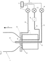
- FIG. 1 shows a sketch of a blown film line 15 in which a blown film tube 1 is extruded from a blow head 2 and conveyed away in the conveying direction z.
- the depiction of blowers or cooling devices was addressed in figure 1 waived.
- the material of the blown film tube 1 is initially still in the form of a melt-like extrudate. In the frost area 3, however, the extrudate turns into film, which then runs through the calibrating basket 4.
- the tubular film is laid flat between the flattening plates 5a and 5b and squeezed in the squeezing device 6 to the squeezing rollers 6a and 6b.
- the tubular film 1 is then in the form of the flattened tubular film 7 .
- the dot-dash line 11 designates the line of symmetry of the blown film tube 1 .
- the flattened film tube 7 is passed on over the transport roller 12 .
- the flattened tubular film is then fed to a winding point.
- the cooling fan device 20 generally removes air from the interior of the film tube 1 via the air discharge line 21 and the ventilation pipe 22.
- the volume of air that is discharged from the interior of the tube by this fan device 20 is essentially equal to the air volume per unit of time, which of the blower device 23 via the air supply line 24 to the inner cooling ring 25 and blown by it into the interior of the film tube 1 .
- the air supply tube 24 is often provided with a flap device 26, with which the air supply into the interior of the film tube can be controlled or regulated.
- the blower 27 directs air via the air supply line 28 to the outer cooling ring 29, which extrudes the air onto the film tube 1.
- the various arrows 30 each indicate the direction of the air or the air flow.
- the position of the frost line, which is in figure 1 is provided with the reference number 3 can be optimized.
- a stronger cooling capacity leads to the frost line being formed closer to the blow head 2 .
- a drop in the blower output means that the frost area 3 moves in the direction of the conveying direction z of the blown film tube.
- the cooling fan performance can be affected by the speed of the fan wheels; however, it is also possible to use flaps 26 for this purpose. It has been shown that when using the method according to the invention, it is advantageous to vary the rotational speed of the fans, since they can be used to bring about more constant changes in the cooling air flow.
- the cooling fan power is controlled with the control device 31 .
- the control device 31 is connected to the cooling fans 20, 23 and 27 via the control lines 32.
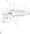
- FIG 3 is another blown film line as in figure 1 shown.
- the same reference numbers were used.
- the system components of the second calibration basket 14, central hose guide 13 and side gusset device 16 were also shown.
- the machine components belong together with those already in figure 1 Components shown, first calibrating basket 4, flattening 5 and squeezing 6 to the film-guiding machine components.
- Other system components that affect the foil are the cooling rings 29 and 25, which are only figure 2 were shown.
Description
Die Erfindung betrifft ein Verfahren gemäß Anspruch 1. Blasfolienanlagen sind aus zahlreichen Druckschriften (z. B.
Oft werden die Folienschläuche sowohl von außen als auch von innen gekühlt. Die Innenkühlung bringt besondere technische Probleme mit sich, da die gerade extrudierten Folienschläuche oft eine geschlossene Folienblase bilden, aus der die Kühlungsluft auch wieder heraus muss.
Der Übergang des Folienmaterials von einer Kunststoffschmelze zu einer immer noch sehr heißen Folie findet bei modernen Extrusionsanlagen in der Regel kurz nach der Extrusion der Schmelze aus einem dafür vorgesehenen Ringspalt statt. Der Ort, an dem sich die Schmelze zur Folie wandelt, wird oft fälschlicherweise als "Frostlinie" bezeichnet. In der Realität ist diese Übergangsstelle jedoch ein ringförmiger Bereich der Umfangsfläche des Schmelze- beziehungsweise Folienschlauches. Dieser Bereich besitzt eine durchaus nennenswerte Ausdehnung in der Transportrichtung des Folienschlauches, die von einigen Millimetern bis zu einigen Dutzend Zentimetern reichen kann. In diesem Bereich nehmen die ungeordneten Makromoleküle der Schmelze zumindest teilweise eine geordnete oder zumindest geordnetere Kristalitstruktur an. Obwohl es bei Kunststoffen eben nicht zu einem schlagartigen, definierten Phasenübergang - wie er beim Übergang von Wasser zu Eis stattfinden kann - kommt, ändern sich die Eigenschaften der Folienschmelze durch diese Wandlung zur immer noch sehr heißen Folie doch in einer für die Folienherstellung maßgeblichen Weise. So vermindert sich die Reckfähigkeit und steigert sich die Stabilität und Widerstandsfähigkeit des Folienmaterials durch diesen Übergang entscheidend. Der angesprochene Übergangsbereich wird aufgrund der Parallelen zum Gefrieren von Wasser im Folgenden "Frostbereich" genannt.
Aufgrund der Änderung des Reckverhaltens und der Widerstandsfähigkeit beim Durchlauf durch den Frostbereich werden die oft bei der Blasfolienherstellung verwendeten Kalibrierkörbe (siehe
Wenn der Frostbereich in den Kalibrierkorb hineinwandert, kann der Kalibrierkorb die Folienschmelze beschädigen. In diesem Fall ist es auch wahrscheinlich, dass das weichere Schmelzematerial vor Erreichen des Kalibrierkorbes einen "Bauch" ausbildet, das heißt, dass der Durchmesser des Schlauches vor Erreichen des Kalibrierkorbes größer ist als der des Kalibrierkorbes. Auch dieser Zustand ist höchst unerwünscht und wird von den Maschinenbedienern mit einer Regelung der Gebläse beantwortet, um Kühlverhalten und Innendruck der Folienblase anzupassen. Aufgrund der Schwierigkeiten, die diese Regelung mit sich bringt und der Trägheit derselben kommt es hierbei nicht selten zu einem Pumpverhalten im Bereich des dem Kalibrierkorb vorgelagerten "Bauches". Dieses Pumpverhalten führt zu umfangreichen Folienschäden oder gar zum Abriss der Folienblase.
Ein Frostbereich, der zu weit vor dem beziehungsweise unterhalb des Kalibrierkorbes liegt, kann dazu führen, dass die Folie nicht im gewünschten Maße ausgereckt wird und das gewünschte Format nicht erreicht. Auch bei Blasfolienanlagen ohne Kalibrierkorb ist die Einstellung der Lage des Frostbereichs von großer Bedeutung.The invention relates to a method according to
The foil tubes are often cooled both from the outside and from the inside. Internal cooling entails particular technical problems, since the film tubes that have just been extruded often form a closed film bubble, from which the cooling air has to escape again.
In modern extrusion systems, the transition of the film material from a plastic melt to a still very hot film usually takes place shortly after the melt has been extruded from an annular gap provided for this purpose. The place where the melt turns into foil is often incorrectly referred to as the "frost line". In reality, however, this transition point is an annular area of the peripheral surface of the melt or film tube. This area has a size that is definitely worth mentioning in the transport direction of the film tube, which can range from a few millimeters to a few tens of centimeters. In this area, the disordered macromolecules of the melt at least partially assume an ordered or at least more ordered crystallite structure. Although there is no sudden, defined phase transition in the case of plastics - as can occur when there is a transition from water to ice - the properties of the film melt change as a result of this change to the film, which is still very hot, in a way that is decisive for film production. The ability to stretch is reduced and the stability and resilience of the film material is significantly increased by this transition. Due to the parallels to the freezing of water, the transition area mentioned will be referred to below as the "frost area".
Due to the change in the stretching behavior and the resistance when passing through the freezing area, the calibration baskets often used in blown film production (see
If the frost area migrates into the calibrating basket, the calibrating basket can damage the foil melt. In this case, it is also probable that the softer melt material forms a "bulge" before it reaches the calibration basket, which means that the diameter of the hose before it reaches the calibration basket is larger than that of the calibration basket. This condition is also highly undesirable and is answered by the machine operators by controlling the blowers in order to adapt the cooling behavior and internal pressure of the film bubble. Due to the difficulties that this regulation entails and the inertia of the same, it is not uncommon for pumping behavior to occur in the area of the "belly" in front of the calibration basket. This pumping behavior leads to extensive film damage or even the tearing of the film bubble.
A frost area that is too far in front of or below the calibration basket can result in the film not being stretched out to the desired extent and not reaching the desired format. Setting the position of the frost area is also of great importance for blown film systems without a calibration basket.
Eine besondere Herausforderung stellt die Einstellung des Frostbereichs bei Formatwechseln dar, die zur Abarbeitung eines neuen Auftrags durchgeführt wurden. Oft sind die Beträge der Formatumstelungen in diesem Zusammenhang besonders groß und Überschreiten die Änderung bei Regelungsvorgängen während der Bearbeitung um ein Vielfaches.A particular challenge is setting the frost range for format changes carried out to process a new order. The amounts of the format changes are often particularly large in this context and exceed the change in control processes during processing many times over.
Bei einem Formatwechsel, bei dem sich bedeutende physikalische Größen zwischen dem Ausgangsformat und dem Endformat nennenswert ändern, ist es sehr schwer, die Lage des Frostbereichs zu optimieren. Mit dem Wort "optimieren" ist im vorliegenden Zusammenhang gemeint, dass der Frostbereich nach einem Formatwechsel sowohl eine andere als auch eine gleiche Position in der Transportrichtung des Folienschlauchs als Solllage einnehmen kann. Oft ändert sich die Sollposition des Frostbereichs von Auftrag zu Auftrag, was auch eine Änderung der Position des Kalibrierkorbes notwendig machen kann.
Da sich auch eine Messung der Lage des Frostbereichs nach dem Stand der Technik zumindest bei vielen Folienmaterialien sehr schwierig gestaltet, ist der Maschinenbediener bei dieser Arbeit auf seine Erfahrung, sein Gefühl und auf viel Geduld angewiesen. Oft versucht der Maschinenbediener insbesondere bei der Formatumstellung die Lage der Frostlinie zu ertasten (also quasi zu messen), um sinnvolle Gebläseeinstellung durch die Bedienung von Steuerungsknöpfen oder Luftklappen in den Gebläseleitungen vornehmen zu können. Diese Arbeiten sind anstrengend und langwierig. Solange die Lage des Frostbereiches nicht optimiert ist, wird Folie minderer Qualität hergestellt.It is very difficult to optimize the position of the frost zone when there is a change of format, in which significant physical parameters change significantly between the initial format and the final format. In the present context, the word “optimize” means that after a format change, the frozen area can assume either a different or the same position in the transport direction of the tubular film as the target position. The target position of the frost area often changes from order to order, which can also make it necessary to change the position of the calibration basket.
Since measuring the position of the frost area according to the prior art is also very difficult, at least with many film materials, the machine operator has to rely on his experience, his feeling and a lot of patience for this work. The machine operator often tries to feel the position of the frost line (i.e. to measure it, so to speak), especially when changing the format, in order to be able to make a sensible blower setting by operating control buttons or air flaps in the blower lines. This work is exhausting and tedious. As long as the position of the frost area is not optimized, film of inferior quality will be produced.
Die
Daher besteht die Aufgabe der vorliegenden Erfindung darin, ein Verfahren zur Einstellung der Formate von Folienschläuchen, welche von Blasfolienanlagen extrudiert werden, vorzuschlagen,
- bei dem das Folienschlauchformat von einem Ausgangsformat eines Folienschlauches auf ein Endformat eines Folienschlauches umgestellt wird
- und bei dem während der Formatumstellung die Lage des Frostbereiches durch eine Einstellung der Leistung der Kühlgebläseleistung optimiert wird, das für den Maschinenbediener komfortabler und schneller durchführbar ist.
- in which the film tube format is changed from an initial format of a film tube to a final format of a film tube
- and in which the position of the frost area is optimized during the format changeover by adjusting the power of the cooling fan power, which can be carried out more conveniently and quickly for the machine operator.
Diese Aufgabe wird durch Anspruch 1 gelöst. Für die Zwecke der vorliegenden Anmeldung wird unter dem Begriff Formatwechsel eine Änderung der physikalischen Parameter der Folienblase verstanden. Zu diesen physikalischen Parametern zählen vor allem der Durchmesser der Folienblase (möglicherweise am Frostbereich oder im Kalibrierkorb zu messen, wird in der Regel jedoch nachträglich über die Breite des flachgelegten Folienschlauches ermittelt), die natürlich zu einer Veränderung der Fläche der Folie führt. Ein anderer wichtiger physikalischer Parameter ist der (Massen)Durchsatz der Extrusionsanlage pro Zeiteinheit. Auch die Abzugsgeschwindigkeit kann sich ändern und von Wichtigkeit sein. Natürlich führt auch eine Änderung des Folienmaterials, die man auf den ersten Blick als chemische Änderung verstehen würde, zu einer Änderung physikalischer Parameter, wie der Extrudattemperatur, der Temperatur, bei der der Frostbereich durchschritten wird, der Wärmekapazität der Folie usw. Auch diese Größen können physikalische Parameter im Sinne dieser Anmeldung sein.
Das Wort Parameter versteht sich damit als kennzeichnende Größe, mit deren Hilfe Aussagen über den Aufbau und die Leistungsfähigkeit der Anlage möglich sind. In der Regel betrifft oder ist ein solcher physikalischer Parameter eine physikalische Größe, die durch Maßeinheit und Maßzahl quantifizierbar ist.
Der Formatwechsel kann durch eine "bewusst" oder "gesteuert" herbeigeführte Änderung beipielsweise bei einem Auftragswechsel herbeigeführt werden. Eine bewusste Änderung wäre beispielsweise eine Änderung eines oder mehrerer physikalischer Parameter, die ein Maschinenbediener beim Auftragswechsel durchführt. Eine gesteuerte Änderung könnte eintreten, wenn die Steuervorrichtung automatisch, beispielsweise aufgrund einer abgespeicherten Arbeitsanweisung, solche Veränderungen vornimmt. Diese Arten von Formatwechseln können sowohl während der laufenden Produktion als auch bei Stillstand der Anlage durchgeführt werden.
Im Sinne der vorliegenden Anmeldung tritt ein Formatwechsel jedoch auch dann ein, wenn innerhalb des laufenden Produktionsbetriebes Regelungs- oder Steuerungsvorgänge stattfinden, die physikalische Parameter betreffen. Solche Vorgänge werden in der Regel veranlasst, um die Beschaffenheit der Folie und des gesamten Produktionsprozesses innerhalb der Toleranzbereiche um bestimmte Sollwerte zu halten.
Auch diese Form der Änderung des Folienschlauchformats kann von dem Maschinenbediener vorgenommen oder automatisch veranlasst werden. In der Regel liegen diesen Änderungen Messwerte zugrunde, die beispielsweise die Lage des Frostbereichs betreffen. Daher kann man diese Änderungen im weitesten Sinne als Regelungsverfahren für das Folienschlauchformat bezeichnen. Die auftragsbezogene Variante des Formatwechsels kann man auch einfach als Auftragswechsel oder Formatumstellung bezeichnen.This object is solved by
The word parameter is understood as a characteristic value, with the help of which statements about the structure and the performance of the system can be made. As a rule, such a physical parameter relates to or is a physical quantity that can be quantified by a unit of measurement and a number of measurements.
The format change can be brought about by a "deliberately" or "controlled" change, for example when changing jobs. A deliberate change would be, for example, a change in one or more physical parameters that a machine operator makes when changing jobs. A controlled change could occur if the control device makes such changes automatically, for example on the basis of a stored work instruction. These types of format changes can be carried out both during ongoing production and when the system is at a standstill.
However, within the meaning of the present application, a format change also occurs if regulation or control processes that affect physical parameters take place within the ongoing production operation. Such processes are usually initiated in order to keep the quality of the film and the entire production process within the tolerance ranges around certain target values.
This form of changing the tubular film format can also be carried out by the machine operator or initiated automatically. As a rule, these changes are based on measured values that relate to the position of the frost area, for example. Therefore, these changes can be described in the broadest sense as control processes for the tubular film format. The order-related variant of the format change can also be referred to simply as an order change or format conversion.
Es ist einzusehen, dass sich weitere physikalische Größen als Folge der Änderung der genannten Größen ändern. Zu diesen Größen gehört zum Beispiel die Foliendicke, die zum Beispiel vom Extrudatdurchsatz pro Zeiteinheit, von der Abzugsgeschwindigkeit und dem Durchmesser der Folienblase abhängt.
Alle diese und weitere Größen, die sich bei auftragsbezogenen Änderungen verändern, können physikalische Größen im Sinne dieser Anmeldung sein.
Das erfindungsgemäße Verfahren kommt aber oft mit einer Teilmenge all dieser Größen aus. Es hat sich durch theoretische und praktische Untersuchungen gezeigt, dass auf einige der aufgelisteten und tatsächlich veränderten Größen bei der Durchführung des erfindungsgemäßen Verfahrens verzichtet werden kann.
Des weiteren wird das Wort "Steuerung" als Unterbegriff zu Regelung verstanden, das heißt dass die Steuerung und die Steuersignale im Sinne der vorliegenden Druckschrift auch Bestandteile einer Regelung sein können.
Mit Kühlgebläseleistung ist die Wirkung der Leistung des Kühlgebläses zu verstehen. In erster Linie wird hierdurch der Luftdurchsatz pro Zeiteinheit beeinflusst. In der Regel geschieht dies nach dem Stand der Technik durch Klappen, die in den oder am Ende der Gebläseleitungen angebracht sind und deren Stellung den Luftdurchsatz beeinflusst. Bei dem erfindungsgemäßen Verfahren ist es von besonderem Vorteil, wenn die Gebläseleistung lediglich über die Drehzahl der Ventilatoren eines, mehrerer oder gar aller Kühlgebläse der Blasfolienanlage vorgenommen wird. In diesem Fall kann die Steuerung der Kühlluftzufuhr klappenlos vorgenommen werden. So ergibt sich ein besonders stetiger Verlauf der Änderung der Kühlgebläseleistung. Eine Drehzahländerung kann unter anderem durch eine Änderung des Betrages des drehmomentbildenden Stromes, aber auch durch Bremsen an den Ventilatoren vorgenommen werden.It can be seen that other physical quantities change as a result of the change in the quantities mentioned. These variables include, for example, the film thickness, which depends, for example, on the extrudate throughput per unit of time, on the take-off speed and the diameter of the film bubble.
All of these and other variables that change with order-related changes can be physical variables within the meaning of this application.
However, the method according to the invention often manages with a subset of all these variables. It has been shown by theoretical and practical investigations that some of the variables listed and actually modified can be dispensed with when carrying out the method according to the invention.
Furthermore, the word "control" is understood as a sub-term for regulation, which means that the control and the control signals can also be components of a regulation within the meaning of the present document.
Cooling fan performance means the effect of cooling fan performance. This primarily influences the air throughput per unit of time. As a rule, according to the state of the art, this is done by means of flaps which are fitted in or at the end of the blower lines and the position of which influences the air throughput. In the method according to the invention, it is of particular advantage if the blower output is adjusted only via the speed of the fans of one, several or even all of the cooling fans of the blown film plant. In this case, the cooling air supply can be controlled without flaps. This results in a particularly steady profile of the change in the cooling fan output. A speed change can be made, among other things, by changing the magnitude of the torque-generating current, but also by braking the fans.
Physikalische Parameter, die vorteilhafterweise zur Durchführung des erfindungsgemäßen Verfahrens genutzt werden können, sind auch physikalische Parameter von Zwischenformaten. So ist es zum Beispiel denkbar, dass die Steuervorrichtung bei einer Änderung der Fläche der Folienblase Zwischenwerte zwischen Anfangs- und Endformat ermittelt und diese bei der Generierung der Steuersignale berücksichtigt.
Überhaupt gehört die Fläche der Folienblase - die ja in bekannter Weise von verwandten Größen wie dem Durchmesser der Folienblase abgeleitet werden kann - zu den wichtigeren Parametern. Bei der Größe der Folienblase ist die Fläche des Teils derselben von besonderem Interesse, der sich zwischen ringförmigen Spalt und Frostbereich (hier vor allem Solllage) oder, wenn man so will, zwischen ringförmigem Spalt und Kalibrierkorb erstreckt. Ein anderer sehr wichtiger Parameter ist der Extrudatdurchsatz pro Zeiteinheit.
Eine Möglichkeit, den Werten der physikalischen Parameter Steuersignale zuzuordnen, besteht darin, diesen Werten in Datenbanken Informationen zuzuordnen. Der Fachmann bezeichnet solche Datenbanken häufig als Kalibriertabelle. Die Informationen können Daten sein, die bei der Generierung der Steuersignale zugrunde gelegt werden. Es können jedoch auch gleich die Steuersignale selbst in einer solchen Datenbank abgelegt werden.
Die Informationen können empirisch oder rechnerisch ermittelt worden sein. Oft wird man jedoch auch "Mischverfahren" anwenden, das heißt man wird, ausgehend von empirischen Werten, mit analytischen oder numerischen Methoden Parameteränderungen berücksichtigen. Es hat sich jedoch gezeigt, dass bei der Anwendung des erfindungsgemäßen Verfahrens bereits dann gute Ergebnisse erzielt werden, wenn physikalische Parameter von der Steuervorrichtung direkt mit Hilfe von Rechenvorschriften weiter veredelt und so bei der Generierung der Steuersignale berücksichtigt werden.
Insbesondere bei einer zunächst ausschließlich durch einen Auftragswechsel bedingten Formatumstellung kann "direkt" in diesem Zusammenhang heißen, dass während oder kurz vor der Umstellung keine Messungen oder ähnliches stattfinden, sondern dass die Maschinensteuerung der Änderung der Gebläseleistung lediglich physikalische Parameter der gewünschten eingestellten Anfangs- und Endzustände zugrunde legt (natürlich könnten auch hier die Anfangszustände gemessen worden sein). Insbesondere bei der Folienfläche zwischen Kalibrierkorb beziehungsweise Frostbereich und Ringspalt des Blaskopfes und den der Fläche verwandten physikalischen Größen wie Höhe des Kalibrierkorbes ist ein solches Verfahren vorteilhaft.Physical parameters that can advantageously be used to carry out the method according to the invention are also physical parameters of intermediate formats. For example, it is conceivable that the When the area of the film bubble changes, the control device determines intermediate values between the initial and final format and takes these into account when generating the control signals.
In general, the area of the film bubble - which can be derived in a known manner from related variables such as the diameter of the film bubble - is one of the more important parameters. With regard to the size of the film bubble, the area of the part of the same that extends between the ring-shaped gap and the frost area (here primarily the target position) or, if you will, between the ring-shaped gap and the calibration basket, is of particular interest. Another very important parameter is the extrudate throughput per unit time.
One way to associate control signals with the values of the physical parameters is to associate information with those values in databases. Those skilled in the art often refer to such databases as calibration tables. The information can be data on which the generation of the control signals is based. However, the control signals themselves can also be stored in such a database.
The information may have been determined empirically or by calculation. However, "mixed methods" are often also used, which means that, based on empirical values, parameter changes are taken into account with analytical or numerical methods. However, it has been shown that when using the method according to the invention, good results are already achieved when physical parameters are further refined directly by the control device with the aid of calculation specifications and are thus taken into account when generating the control signals.
In particular, in the case of a format changeover initially caused exclusively by an order change, "direct" in this context can mean that no measurements or the like take place during or shortly before the changeover, but rather that the machine control of the change in the blower output only uses physical parameters of the desired set initial and final states (of course, the initial states could also have been measured here). Such a method is particularly advantageous for the film surface between the calibrating basket or frost area and the annular gap of the blow head and the physical variables related to the surface, such as the height of the calibrating basket.
Trotz all dieser positiven Befunde ist es oft von Vorteil, wenn der Maschinenbediener weitere Einstellungen - in der Regel Feineinstellungen - vornimmt. Dieser Umstand ist unter anderem darin begründet, dass eben in der Regel bei erfindungsgemäßen Verfahren nicht alle physikalischen Parameter der komplexen Zusammenhänge berücksichtigt werden können. So sind zum Beispiel einige Änderungen der Umwelteinflüsse wie der Umgebungstemperatur und von Zugluft durchaus nicht ohne Einfluss auf die Lage des Frostbereichs.
Oft wird sich jedoch nach einem Formatwechsel mit oder ohne Zusatzeinstellungen des Bedieners ein statischer Zustand einstellen, der der Produktion der Folie sehr zu Gute kommt.
Bei langen Produktionszyklen werden sicherlich immer wieder neue Feineinstellungen vorgenommen, um beispielsweise der Änderung von Umwelteinflüssen gerecht zu werden.
Die auf diese Weise erreichten statischen Zustände eignen sich sehr gut als Ausgangszustand für die erfindungsgemäße Steuerung der Kühlgebläseleistung:
Es hat sich gezeigt, dass es oft vorteilhafter ist, die Änderungen der Kühlgebläseleistungen ausgehend von dem tatsächlich eingestellten Anfangszustand der Gebläseleistungswerte vorzunehmen als von irgendwelchen errechneten oder empirisch ermittelten Werten auszugehen, die man im Speicher der Steuerungsvorrichtung abgelegt hat. Dieser Umstand ist in der Regel der oben beschriebenen ständigen feinfühligen Anpassung der Gebläseleistung an sich ändernde äußere Parameter geschuldet.Despite all these positive findings, it is often advantageous if the machine operator makes further adjustments - usually fine adjustments. This circumstance is due, among other things, to the fact that, as a rule, not all physical parameters of the complex relationships can be taken into account in the method according to the invention. For example, some changes in environmental influences such as ambient temperature and drafts are not without an impact on the location of the frost area.
However, after a format change with or without additional settings by the operator, a static condition will often set in, which is very beneficial for the production of the film.
With long production cycles, new fine adjustments are certainly made again and again, for example to do justice to changes in environmental influences.
The static states achieved in this way are very well suited as a starting state for controlling the cooling fan output according to the invention:
It has been found that it is often more advantageous to make the changes in cooling fan performance from the actual set initial condition of the fan performance values than to start from any calculated or empirically determined values stored in the controller's memory. This circumstance is usually due to the constant, sensitive adjustment of the blower output to changing external parameters, as described above.
Zu den Vorteilen der klappen- oder ventillosen Regelung im Zusammenhang mit der vorliegenden Erfindung ist noch einmal Folgendes anzumerken:
Offenbar führt die schnelle Regelung der Gebläseleistung mit den Klappen zu zu starken, oft unstetigen Änderungen der Gebläseleistung, welche unter anderem die nachstehend genanten unerwünschten Entwicklungen nach sich ziehen können:
- eine zu schnelle Verschiebung der Frostlinie über das gewünschte Maß hinaus,
- ein Pumpverhalten der Folienblase (oben angesprochen) oder
- ein Zusammenfallen (Kolabieren) der Folienblase.
Apparently, the fast control of the fan power with the flaps leads to excessive, often discontinuous changes in the fan power, which can result in the following undesirable developments:
- a too rapid shift of the frost line beyond the desired level,
- a pumping behavior of the film bubble (mentioned above) or
- collapse of the film bubble.
Es hat sich gezeigt, dass noch größere Unstetigkeiten auftreten können, wenn in Folge der Betätigung der Klappe in dem betroffenen Luftstrom zum Beispiel Phasenübergänge zwischen laminaren und turbulenten Strömungen auftreten.It has been shown that even greater discontinuities can occur if, for example, phase transitions between laminar and turbulent flows occur in the affected air flow as a result of the actuation of the flap.
Versuche haben gezeigt, dass eine Beeinflussung der Drehzahl zumindest eines Lüftungsrotors mit Hilfe der Mittel zur Ableitung und Umwandlung von Bewegungsenergie zu einer ausreichend schnellen aber stetigeren Änderung der Kühlgebläseleistung führt.
Mit "Ableitung und Umwandlung von Bewegungsenergie" ist zunächst jede Maßnahme gemeint, die die Rotationsbewegung des Lüftungsrotors bremst.
In diesem Zusammenhang ist auch die Bedeutung des Wortes "zuschaltbar" zu beachten. Gemeint ist, dass die "Mittel zur Ableitung und Umwandlung von Bewegungsenergie" eben bei Bedarf zuschaltbar sind.
Die zuschaltbare Ableitung und Umwandlung von Bewegungsenergie kann in diesem Zusammenhang auch durch mechanische Bremsen vorgenommen werden, welche Bewegungsenergie während eines Bremsvorgangs beispielsweise in mechanische oder durch Reibung in thermische Energie umsetzen. Wirbelstrombremsen können kinetische Energie durch Induktion und Ohmschen Widerstand ebenfalls in thermische Energie wandeln.
Eine im Betrieb andauernde bzw. inhärente Wandlung von kinetischer Energie (beispielsweise durch Reibung in den Lagern des Lüftungsrotors oder durch Luftwiderstand) ist durch das Attribut zuschaltbar ausgeschlossen.
Bei Lüftungsrotoren, die mit Elektromaschinen angetrieben werden, ist es vorteilhaft, wenn die Motoren einen Leistungssteller umfassen, welcher die Elektromaschine so beschalten kann, dass diese im generatorischen Betrieb arbeitet. In dieser Situation wird der Rotor gebremst und Bewegungsenergie des Rotors wird in elektrische Energie gewandelt. Diese ist aus dem Stromkreis der betreffenden Elektromaschine auszuscheiden. Dies kann durch eine Rückspeisung dieser Energie ins Stromnetz vorgenommen werden. Hierzu kann eine weitere leistungselektronische Vorrichtung, oft Endstufe genannt, vorgesehen werden. Es hat sich gezeigt, dass bei solchen Rückspeisevorgängen jedoch Probleme mit der elektromagnetischen Verträglichkeit in dem angesprochenen Stromnetz aufkommen können.
Eine weitere vorteilhafte Möglichkeit besteht in dem "Verbrennen" des anfallenden Stromes durch einen Bremswiderstand (Wandlung in Wärmeenenergie durch Widerstand).
Die Zuführung des "freigewordenen" (aus der kinetischen Energie der Rotationsbewegung gewandelten) elektrischen Stromes zu einem weiteren Elektromotor hilft jedoch, Energie zu sparen. Hierbei ist es vorteilhaft, wenn es sich bei der weiteren Elektromaschine um ein Maschinenelement handelt, welches hauptsächlich im Dauerbetrieb läuft und dabei möglichst gleichförmig elektrische Leistung benötigt. Insbesondere in tropischen Ländern kann auch ein Belüftungsmotor der Klimaanlage für die Extruderhalle diese Anforderungen erfüllen.
In diesem Zusammenhang sind jedoch auch Elektromaschinen zu nennen, die an der Außenkühlung derselben oder einer anderen Blasfolienanlage mitwirken. Auch die Motoren der Extruder arbeiten während des Dauerbetriebs der Anlage gleichmäßig.
Die meisten Brems- oder Regelvorgänge fallen im Bereich der Innenkühlung an, weshalb sich hier alle erfindungsgemäßen Maßnahmen am Meisten empfehlen. Es ist von großem Vorteil Elektromaschinen, die der Innenkühlung zugeordnet sind, bei Bedarf generatorisch zu betreiben und den gewonnenen Strom den Motoren anderer Gebläse zuzuführen.
Trotz der eingangs geschilderten Nachteile der Steuerung und Regelung der Gebläseleistung beziehungsweise des Blasluftstroms durch Klappen, kann es doch von Vorteil sein, solche an der Blasfolienanlage vorzusehen und insbesondere bei Änderungen großen Betrags einzusetzen.
In diesem Zusammenhang können durch die bremsbaren Lüftungsrotoren auch Ausgleichsmaßnahmen bei zu unstetigen Gebläseleistungsänderungen vorgenommen werden.
Erfindungsgemäß ist vorgesehen, dass zumindest ein Teil der Anlagenkomponenten, bei denen bei dem Formatwechsel Änderungen ihrer Einstellungen vorgenommen werden, diese Änderungen zeitversetzt erfahren. Zu den betroffenen Komponenten können zunächst alle Vorrichtungen gehören, mit denen sich physikalische Parameter einstellen lassen. Vor allem sind mit Anlagenkomponenten im vorliegenden Zusammenhang jedoch Vorrichtungen gemeint, die direkt oder indirekt Einfluss auf den extrudierten Folienschlauch nehmen. Das sind zunächst die zur Kalibrierung und Führung des Folienschlauches vorgesehenen Komponenten, die oft in Berührung mit der Folie oder dem Folienschlauch geraten.
Gemäß der Erfindung gehören unter anderem der oder die Kalibrier- oder Stützkörbe, die Schlauchzentralführung, die Seitenfalteneinrichtung, die Flachlegeeinrichtung und die Abquetscheinrichtung dazu. Diese Anlagenkomponenten gelten als erfindungsgemäße folienführende Elemente, auch wenn bei einem Teil dieser Elemente ein direkter Kontakt zwischen der Folie und der Anlagenkomponente beispielsweise durch ein Luftpolster vermieden wird. Die "Änderung" beim betreffenden Formatwechsel besteht bei diesen Komponenten vor allem in einer Anpassung derselben an den jeweiligen Schlauchquerschnitt. Hierzu können zum Beispiel auch Kalibrierkörbe vorgesehenen werden, die von der Steuervorrichtung automatisch "geändert" (v.a. Einstellung des Innendurchmessers) werden können.
Neben diesen schlauchführenden Anlagenkomponenten haben auch noch andere Komponenten direkten Einfluss auf den gerade extrudierten Folienschlauch. Zu diesen Anlagenkomponenten gehören die verschiedenen Innen- und Außenkühleinrichtungen. Bei diesen Kühleinrichtungen ist die Änderung in der Regel bei dem physikalischen Parameter Luftvolumen pro Zeiteinheit oder Temperatur der Kühlluft vorzunehmen. Mittlerweile werden Anlagen mit einer Abfolge verschiedener Innen- und Außenkühleinrichtungen ausgestattet. So ist es bekannt zwei oder mehr Außen- oder Innenkühlringe oder andere Außen- oder Innenkühlvorrichtungen in Transportrichtung der Folie hintereinander anzuordnen. Es hat sich ebenfalls als vorteilhaft erwiesen, die Zeitpunkte zu denen Änderungen der Gebläseleistung oder Lufttemperatur vorgenommen werden, zwischen diesen unterschiedlichen Kühlvorrichtungen (Kühlvorrichtungen sind Anlagenkomponenten) zu variieren - also einen Zeitversatz vorzunehmen. So kann die Leistung des dem ersten Außenkühlring zugeordneten Gebläses früher geändert werden als die des zweiten oder die Leistung der gesamten Innenkühlung früher als die der Außenkühlung.
Mit "zeitversetzt" ist in der vorliegenden Druckschrift gemeint, dass die Änderung zu verschiedenen Zeitpunkten vorgenommen wird oder wirksam wird. "Sukzessive" ist demzufolge ein Unterbegriff zu zeitversetzt, bei dem eine Abfolge stärker betont wird.
Es bleibt festzuhalten, dass an verschiedenen Anlagen verschiedene dieser Maschinenkomponenten vorhanden sind. Oft wird man nur Teilmengen der hier aufgeführten Komponenten finden. Man wird jedoch auch mehr oder andersartige Komponenten finden. Wichtig für die Zwecke dieser Anmeldung ist vor allem, dass diese Maschinenkomponenten Einfluss auf die Folie nehmen und bei der Formatumstellung eine Änderung erfahren.
Erfindungsgemäß ist eine sukzessive Änderung an unterschiedlichen Anlagenkomponenten im laufenden Produktionsbetrieb (hier Gutproduktion) da eine abrupte Umstellung aller Komponenten hier zu zu großen Unstetigkeiten führen kann. Diese Unstetigkeiten können starke Schwankungen physikalischer Parameter der Folie auslösen, die dann wieder ausgeregelt werden müssen. Auch Auftragswechsel können jedoch vorgenommen werden, während die Anlage Material extrudiert. Ein in dieser Weise vorgenommener Auftragswechsel ist in höchstem Maße vorteilhaft wenn so ein Abriss der Folienblase und die damit verbundenen Zeitverlust vermieden werden können.Experiments have shown that influencing the speed of at least one ventilation rotor with the aid of the means for dissipating and converting kinetic energy leads to a sufficiently rapid but more constant change in the cooling fan output.
"Dissipation and conversion of kinetic energy" means any measure that slows down the rotational movement of the ventilation rotor.
In this context, the meaning of the word “switchable” must also be taken into account. What is meant is that the "means for deriving and converting kinetic energy" can be switched on if required.
In this context, the switchable dissipation and conversion of kinetic energy can also be carried out by mechanical brakes, which convert kinetic energy during a braking operation, for example, into mechanical energy or, through friction, into thermal energy. Eddy current brakes can also convert kinetic energy into thermal energy through induction and ohmic resistance.
A conversion of kinetic energy that is ongoing or inherent during operation (e.g. due to friction in the bearings of the ventilation rotor or due to air resistance) is excluded by the switchable attribute.
In the case of ventilation rotors that are driven by electric machines, it is advantageous if the motors include a power controller that can switch the electric machine so that it works in generator mode. In this situation, the rotor is braked and the kinetic energy of the rotor is converted into electrical energy. This must be removed from the circuit of the electric machine in question. This can be done by feeding this energy back into the power grid. A further electronic power device, often referred to as an output stage, can be provided for this purpose. It has been shown, however, that problems with electromagnetic compatibility can arise in the power grid in question with such feed-back processes.
A further advantageous possibility consists in the "burning" of the occurring current through a braking resistor (conversion into thermal energy through resistance).
However, the supply of the "released" electrical current (converted from the kinetic energy of the rotational movement) to another electric motor helps to save energy. It is advantageous here if the additional electric machine is a machine element that runs mainly in continuous operation and requires electrical power that is as uniform as possible. In tropical countries in particular, a ventilation motor for the air conditioning system in the extruder hall can also meet these requirements.
In this context, however, mention should also be made of electric machines that contribute to the external cooling of the same or another blown film system. The motors of the extruders also work evenly during continuous operation of the system.
Most braking or control processes occur in the area of internal cooling, which is why all the measures according to the invention are most recommended here. It is of great advantage to operate electric machines, which are assigned to the internal cooling, as a generator if necessary and to feed the electricity generated to the motors of other fans.
Despite the initially described disadvantages of controlling and regulating the blower output or the blown air flow by means of flaps, it can still be advantageous to provide such flaps on the blown film system and to use them, particularly in the case of large-scale changes.
In this context, compensatory measures can also be taken if the blower output changes too inconsistently by means of the braked ventilation rotors.
According to the invention, it is provided that at least some of the system components in which changes are made to their settings during the format change experience these changes with a time delay. The affected components can initially include all devices with which physical parameters can be set. Above all, however, plant components in the present context mean devices that have a direct or indirect influence on the extruded film tube. First of all, there are the components provided for calibrating and guiding the film tube, which often come into contact with the film or the film tube.
According to the invention, this includes, among other things, the calibration or support basket(s), the central hose guide, the side gusset device, the flattening device and the squeezing device. These system components are regarded as film-guiding elements according to the invention, even if direct contact between the film and the system component is avoided in some of these elements, for example by means of an air cushion. In the case of these components, the "change" in the relevant format change consists above all in an adaptation of the same to the respective tube cross-section. For this purpose, for example, calibration baskets can also be provided, which can be automatically "changed" by the control device (above all adjustment of the inside diameter).
In addition to these tube-guiding system components, other components also have a direct influence on the film tube that has just been extruded. These system components include the various internal and external cooling devices. In the case of these cooling devices, the change is usually to be made in the physical parameter air volume per unit of time or temperature of the cooling air. Plants are now equipped with a sequence of different internal and external cooling devices. It is known to arrange two or more external or internal cooling rings or other external or internal cooling devices one behind the other in the transport direction of the film. It has also proven to be advantageous to vary the times at which changes are made to the blower output or air temperature between these different cooling devices (cooling devices are system components), ie to make a time offset. Thus, the output of the fan assigned to the first external cooling ring can be changed earlier than that of the second, or the output of the entire internal cooling system can be changed earlier than that of the external cooling system.
In the present publication, “delayed” means that the change was made at different points in time becomes or becomes effective. "Successive" is therefore a sub-term too time-delayed, in which a sequence is more strongly emphasized.
It remains to be noted that different of these machine components are present on different systems. Often you will only find subsets of the components listed here. However, you will also find more or different components. For the purposes of this application, it is particularly important that these machine components influence the film and undergo a change when the format is changed.
According to the invention, there is a gradual change to different plant components during ongoing production (here good production), since an abrupt changeover of all components here can lead to excessive discontinuities. These discontinuities can trigger strong fluctuations in the physical parameters of the foil, which then have to be corrected again. However, job changes can also be made while the system is extruding material. An order change made in this way is extremely advantageous if a tearing of the film bubble and the associated loss of time can be avoided.
Erfindungsgemäß ist vorgesehen, dass die Änderungen an den unterschiedlichen Anlagenkomponenten zumindest zum Teil in der Abfolge vorgenommen werden, in der diese Komponenten Einfluss auf die Folie (in der Transportrichtung der Folie) nehmen. Die folienführenden Komponenten nehmen natürlich durch ihre Berührung oder ihre Fürung Einfluss, während bei den Kühlvorrichtungen der Ort der größten Kühlwirkung maßgeblich ist.
Auch die Geschwindigkeit, mit der die Einstellung der Komponenten bei den unterschiedlichen Komponenten aufeinander abfolgt, ist mit der Geschwindigkeit, mit der die Folie an den jeweiligen Komponenten "vorbei" gefördert wird, korreliert.
Durch die dargestellten, bewusst oder gesteuert, als Teil eines Auftragswechsels oder eines Regelvorganges vorgenommenen Formatänderungen kann es passieren, dass sich der Durchmesser des extrudierten Folienschlauches so ändert, dass der flachgelegte Folienschlauch oder die bereits aufgeschnittene Flachfolienbahn zu breit für die zumindest eine der Anlage nachgeordnete Wickelstelle wird. Es ist von Vorteil, wenn die Steuervorrichtung der Anlage in diesem Fall ein Warnsignal oder eine Warnmeldung ausgibt. Zu diesem Zweck sollte es möglich sein, dieser Maschinensteuerung die Breite der Wickelstelle mitzuteilen oder eine allfällige Kommunikation dieser Daten zwischen den Steuervorrichtungen der Anlage und der Wickelstelle zu ermöglichen.
Eine längerfristige Gutproduktion führt in aller Regel zu einem Einschwingen der ihr zugrunde liegenden physikalischen Parameter, wobei die nich gänzlich zu unterdrückenden Änderungen der äußeren Umstände (z. B. Hallentemperatur) zu ständigen Änderungen durch Einstell- Steuer- oder Regelvorgänge führen können.
Trotz dieser Umstände liegt es natürlich in der Absicht eines jeden Maschinenbedieners, möglichst schnell einen einigermaßen statischen Produktionszustand zu erreichen, bei dem die physikalischen Produktionsparameter nur noch mäßig um bestimmte Sollwerte schwanken. Tests haben jedoch ergeben, dass zur möglichst schnellen Herbeiführung eines solchen Zustands zunächst physikalische Parameter einzustellen sind, die sich in überraschender Höhe (Betrag) von den Sollparametern der Gutproduktion unterscheiden.According to the invention, it is provided that the changes to the different system components are made at least in part in the sequence in which these components influence the film (in the transport direction of the film). The film-guiding components naturally have an influence through their contact or their guidance, while the location of the greatest cooling effect is decisive for the cooling devices.
The speed at which the setting of the components in the different components follows one another is also correlated with the speed at which the film is conveyed “past” the respective components.
As a result of the format changes shown, made deliberately or in a controlled manner as part of an order change or a control process, it can happen that the diameter of the extruded film tube changes in such a way that the flattened film tube or the flat film web that has already been cut open is too wide for the at least one winding point downstream of the system will. It is advantageous if the control device of the installation issues a warning signal or a warning message in this case. For this purpose, it should be possible to communicate the width of the winding position to this machine control or to enable any communication of this data between the control devices of the system and the winding position.
A long-term good production usually leads to a settling of the physical parameters on which it is based, whereby the changes in the external circumstances (e.g. hall temperature) that cannot be completely suppressed can lead to constant changes due to adjustment, control or regulation processes.
In spite of these circumstances, it is of course in the intention of every machine operator to achieve a reasonably static production state as quickly as possible, in which the physical production parameters only fluctuate moderately around certain target values. However, tests have shown that in order to bring about such a state as quickly as possible, physical parameters must first be set which differ by a surprising amount (amount) from the target parameters for good production.
Daher ist es vorteilhaft, wenn in der Steuervorrichtung zumindest zwei Klassen physikalischer Parameter abgelegt sind, die jeweils bestimmten Endformaten zugeordnet sind,
- wobei die erste Klasse physikalischer Parameter Sollwerte für den laufenden Produktionsbetrieb (Gutproduktion) eines Auftrages umfasst,
- und wobei die zumindest eine zweite Klasse physikalischer Parameter Sollwerte für den Anfahrbetrieb des betreffenden Auftrages umfasst.
In Bezug auf die Gewinnung der Sollwerte für Anfahr- und Produktionsbetrieb ist wieder zu sagen, dass diese empirisch oder rechnerisch gewonnen werden können. Die Steuervorrichtung der Anlage ist entsprechend zu beaufschlagen. In diesem Zusammenhang wird von Vorteil sein rezeptabhängige Anfahr- und Produktionsparameter zu speichern oder Rechenvorschriften zur Bestimmung derselben vorzusehen.
Die Sollwerte für den Anfahrbetrieb sind auch dann zu verwenden, wenn in Folge eines kurzen Anlagenstillstandes ein neues Anfahren der Anlage notwendig wird.
In diesem vorgenannten Fall ist es - mit oder ohne Sollwerte für den Anfahrbetrieb - von großem Vorteil die Anlage mit einer Art "Kurzzeitgedächtnis zu versehen, das automatisch (regelmäßiges automatisches abspeichern) oder auf Veranlassung des Maschinenbedieners, die augenblicklichen Produktionsparameter genau abspeichert. Auf diese Weise "merkt" sich die Maschine beispielsweise bei der Gutproduktion nicht nur die allgemeinen Sollwerte, sondern auch die sich genau - aufgrund der oben erwähnten ständigen Änderungen durch Einstell- Steuer oder Regelvorgänge - ergebenen augenblicklich eingestellten physikalischen Parameter.
Kommt es in einer solchen Situation zu einer gewollten (z. B. Maschinenreinigung) oder ungewollten (z. B. ungewollter Folienriss oder Stromausfall) Produktionsunterbrechung, so kann die Anlage sogleich mit dem Ziel, die kurz zuvor im Dauerbetrieb optimierten Parameterwerte zu erreichen, angefahren werden. Diese Verfahrensfortbildung spart Zeit, Geld und gegebenenfalls hochqualifizierte Personalressourcen.It is therefore advantageous if at least two classes of physical parameters are stored in the control device, each of which is assigned to specific end formats,
- wherein the first class of physical parameters includes target values for the current production operation (good production) of an order,
- and wherein the at least one second class of physical parameters includes target values for the start-up operation of the order in question.
With regard to obtaining the target values for start-up and production operation, it should again be said that these can be obtained empirically or by calculation. The control device of the system is to be loaded accordingly. In this context, it will be advantageous to store recipe-dependent start-up and production parameters or to provide calculation rules for determining the same.
The setpoints for the start-up operation are also to be used if a new start-up of the system becomes necessary as a result of a brief system standstill.
In this case, it is of great advantage - with or without setpoints for the start-up operation - to provide the system with a kind of "short-term memory" that automatically (regular automatic saving) or at the request of the machine operator saves the current production parameters exactly. In this way For example, during good production, the machine "notes" not only the general target values, but also the precise ones - due to the above-mentioned constant changes through adjustment, control or regulation processes - resulting currently set physical parameters.
If such a situation leads to an intentional (e.g. machine cleaning) or unintentional (e.g. unintentional film tear or power failure) production interruption, the system can be started up immediately with the aim of achieving the parameter values that had just been optimized in continuous operation will. This process training saves time, money and, if necessary, highly qualified personnel resources.
Weitere Ausführungsbeispiele der Erfindung gehen aus der gegenständlichen Beschreibung und den Ansprüchen hervor.
Die einzelnen Figuren zeigen:
- Fig. 1
- Skizze einer Blasfolienanlage
- Fig. 2
- Skizze eines Blaskopfes
- Fig. 3
- Skizze einer Blasfolienanlage mit weiteren Anlagenkomponenten
The individual figures show:
- 1
- Sketch of a blown film line
- 2
- Sketch of a blow head
- 3
- Sketch of a blown film line with additional line components
In
In
Vor dem Hintergrund des bereits ausgeführten ist es von Vorteil, wenn alle in Frage kommenden Anlagekomponenten automatisch umgestellt ("geändert") werden können und wenn diese Änderung von der Steuervorrichtung vorgenommen werden kann.
Against the background of what has already been explained, it is advantageous if all system components in question can be switched over ("changed") automatically and if this change can be made by the control device.
Claims (14)
- A method for setting the formats of film tubes (1), which are extruded by blown film lines (15),- in which the film tube format is converted from an initial format of a film tube (1) to a final format of a film tube (1),- and in which during the format conversion the position of the frost area (3) is optimized by an adjustment of the output of the cooling fan (20, 23, 27),- wherein in order to convert the film tube format, an order-related change of the physical parameters is made, wherein the surface of the film bubble (1) and/or of the extrudate throughput per unit of time and/or the haul-off speed and/or the target position of the frostline (3) in the axial direction (z) of the film bubble (1) are among the physical parameters,- the physical parameters of the initial and the final format of the film tube (1) are stored in the control device (31),- that the control device (31) takes these physical parameters into account when generating control signals,- and that these control signals are used to control the cooling fan output,- wherein at least part of the tube-guiding system components for adapting to the respective tube cross-section when the format is being changed undergo changes, wherein these changes occur with a time delay,- wherein the format change is carried out, while the system is extruding film material,- wherein in the case of at least a part of the system components, in which changes are made to the settings, these changes are made successively, wherein the order, in which changes are made to the different system components, corresponds to the order, in which these system components exert influence on the plastic extrudate or the extruded film in the conveying direction (z) of the film,characterized in that- the length of time, which elapses between changes to different system components, largely corresponds to the length of time, which a certain film material section needs at the current system speed to cover the distance between the areas of influence of the relevant system components.
- The method according to claim 1,
characterized in that
the control device (31) determines physical parameters of the intermediate formats based on physical parameters of the initial and the final format. - The method according to any one of the preceding claims,
characterized in that- information is stored in a storage device of the control device (31),- the specific values of the physical parameters are assigned,- and when these values of said physical parameters are available, these are taken into account when generating the control signals. - The method according to the preceding claim,
characterized in that
the information stored in the storage device is programmed in on the basis of empirical values and obtained with the aid of calculation rules. - The method according to any one of the preceding claims,
characterized in that
the calculating device generates instructions for the generation of control signals from values of physical parameters according to specific calculation rules. - The method according to any one of the preceding claims,
characterized in that
at least one of the fans (20, 23, 27) involved in cooling the film bubble (1) is connected to its air outlet opening in a flapless manner. - The method according to the preceding claim,
characterized in that
all of the fans (20, 23, 27) involved in cooling the film bubble (1) are connected to their air outlet opening in a flapless manner. - The method according to any one of the preceding claims,
characterized in that
a machine operator makes fine adjustments in the fan output, after the control device (31) has set the fan values with the aid of the control signals, which it assigns to the final format. - The method according to any one of the preceding claims,
characterized in that
the control device (31) when determining the control signals takes into account the fan settings set in the initial format during the production of the blown film. - The method according to the preceding claim,
characterized in that
the control device (31) when determining the control signals assumes the fan settings set during the production of the blown film in the initial format and based on the physical parameters of the final state makes changes to the fan settings. - The method according to any one of the preceding claims,
characterized in that
the fans, which are assigned to different cooling devices, are also among the system components, to which changes are made with a delay or successively. - The method according to any one of the preceding claims,
characterized in that
the control device emits a warning signal, when the width of the film laid flat exceeds the maximum working width of the wrapping device due to a format change. - The method according to any one of the preceding claims,
characterized in thatin the control device at least two classes of physical parameters are stored, which in each case are assigned specific final formats,wherein the first class of physical parameters comprises target values for the ongoing production operation for an order,and wherein the at least one second class of physical parameters comprises target values for the start-up operation of the relevant order. - The method according to any one of the preceding claims,
characterized in thatparameters that are currently set before a brief production interruption are temporarily stored,and that these temporarily stored physical parameters are either reset when the production resumes,or are taken as the basis for the determination of physical parameters for the start-up operation.
Applications Claiming Priority (2)
| Application Number | Priority Date | Filing Date | Title |
|---|---|---|---|
| DE102005033205.6A DE102005033205C5 (en) | 2005-07-13 | 2005-07-13 | Method for order-related change of the film tube format from a starting format to a final format and blown film plant, on which this change is feasible |
| PCT/EP2006/006873 WO2007006576A2 (en) | 2005-07-13 | 2006-07-13 | Method for setting the sizes of blown film tubes as well as a blown film system with a control device for carrying out the method |
Publications (3)
| Publication Number | Publication Date |
|---|---|
| EP1904284A2 EP1904284A2 (en) | 2008-04-02 |
| EP1904284B1 EP1904284B1 (en) | 2018-05-30 |
| EP1904284B2 true EP1904284B2 (en) | 2022-02-16 |
Family
ID=37388434
Family Applications (1)
| Application Number | Title | Priority Date | Filing Date |
|---|---|---|---|
| EP06776229.4A Active EP1904284B2 (en) | 2005-07-13 | 2006-07-13 | Method for setting the sizes of blown film tubes |
Country Status (5)
| Country | Link |
|---|---|
| US (2) | US20090045555A1 (en) |
| EP (1) | EP1904284B2 (en) |
| CA (1) | CA2614708C (en) |
| DE (1) | DE102005033205C5 (en) |
| WO (1) | WO2007006576A2 (en) |
Families Citing this family (8)
| Publication number | Priority date | Publication date | Assignee | Title |
|---|---|---|---|---|
| DE102005033205C5 (en) * | 2005-07-13 | 2017-10-12 | Windmöller & Hölscher Kg | Method for order-related change of the film tube format from a starting format to a final format and blown film plant, on which this change is feasible |
| DE102011053921B4 (en) * | 2011-09-26 | 2015-07-30 | Deutsches Zentrum für Luft- und Raumfahrt e.V. | Control of an autoclave manufacturing process |
| DE102016119872A1 (en) | 2016-10-18 | 2016-12-29 | Kdesign Gmbh | Method and device for controlling the dimensional stability of a film tube during its production by means of a blown film extrusion line |
| DE102016119869A1 (en) * | 2016-10-18 | 2018-04-19 | Reifenhäuser GmbH & Co. KG Maschinenfabrik | Method and plant for producing a plastic film |
| CA3055886C (en) | 2017-04-07 | 2022-09-06 | Brampton Engineering Inc. | Adjustable venturi ring |
| IT201700055831A1 (en) * | 2017-05-23 | 2018-11-23 | Syncro S R L | DEVICE AND METHOD TO ADJUST THE THICKNESS PROFILE IN BLOWN FILM PRODUCTION |
| DE102018127679A1 (en) * | 2018-11-06 | 2020-05-07 | Windmöller & Hölscher Kg | Switching device for converting a flat film machine from an input product to a subsequent product |
| US11446854B2 (en) * | 2019-12-16 | 2022-09-20 | Daniel R. Joseph | Method and apparatus for calibration of blown-film extrusion apparatus |
Citations (5)
| Publication number | Priority date | Publication date | Assignee | Title |
|---|---|---|---|---|
| DE2831212A1 (en) † | 1978-07-15 | 1980-01-24 | Dow Chemical Co | Blown film prodn. control - e.g. in revolving tube process, controls air ring supply responsive to pyrometer signal below frost line |
| DE2721609C2 (en) † | 1977-05-13 | 1986-07-10 | Reifenhäuser KG, 5210 Troisdorf | Control device for a plant for the production of blown plastic films |
| US6254368B1 (en) † | 1992-04-20 | 2001-07-03 | Tomy Machinery Manufacturing Col., Ltd. | Plastic molding machine |
| EP1616687A1 (en) † | 2004-07-14 | 2006-01-18 | Kdesign GmbH | Method and apparatus for monitoring the production in the manufacturing of tubular films |
| US7922470B2 (en) † | 2000-04-07 | 2011-04-12 | Joseph Daniel R | Apparatus for automatic control of cage size in an extruded film production line |
Family Cites Families (12)
| Publication number | Priority date | Publication date | Assignee | Title |
|---|---|---|---|---|
| DE1138463B (en) * | 1957-10-21 | 1962-10-25 | Elin Union Ag | Winding arrangement for two-legged single-phase transformers combined into a three-phase group |
| DE2816583A1 (en) | 1978-04-17 | 1979-10-18 | Windmoeller & Hoelscher | METHOD AND DEVICE FOR OPTIMIZING THE OUTPUT PERFORMANCE OF A BLOWED FILM EXTRUDER SYSTEM USING A PROCESS COMPUTER |
| JPH01275123A (en) * | 1988-04-28 | 1989-11-02 | Sekisui Chem Co Ltd | Size-changing system of formed object in inflation molding |
| US5104593A (en) * | 1990-03-21 | 1992-04-14 | Joseph Daniel R | Method and apparatus for gauging and controlling circumference of extrusion-blown film |
| US5288219A (en) * | 1991-03-25 | 1994-02-22 | Battenfeld Gloucester Engineering Co., Inc. | Air ring for controlling blown film thickness |
| DE4137516A1 (en) * | 1991-07-08 | 1993-01-14 | Windmoeller & Hoelscher | METHOD FOR REGULATING THE DIAMETER OF TUBE FILMS PRODUCED IN BLOW FILM PLANTS |
| US5288441A (en) * | 1992-12-24 | 1994-02-22 | Collins Steven L | System and method for extruder frost line detection |
| US5468134A (en) * | 1993-12-01 | 1995-11-21 | Cree; Robert E. | Cooling and thickness control for extruded products |
| DE10015731A1 (en) * | 2000-03-29 | 2001-10-04 | Hosokawa Alpine Ag & Co | Process for controlling the diameter of film tubes during their production in film blowing systems |
| CN1287973C (en) * | 2002-08-30 | 2006-12-06 | 可乐丽股份有限公司 | Apparatus and method for producing blown film |
| ES2280666T3 (en) * | 2003-06-17 | 2007-09-16 | REIFENHAUSER GMBH & CO. MASCHINENFABRIK | DEVICE FOR MANUFACTURING A THERMOPLASTIC SYNTHETIC MATERIAL FILM. |
| DE102005033205C5 (en) * | 2005-07-13 | 2017-10-12 | Windmöller & Hölscher Kg | Method for order-related change of the film tube format from a starting format to a final format and blown film plant, on which this change is feasible |
-
2005
- 2005-07-13 DE DE102005033205.6A patent/DE102005033205C5/en active Active
-
2006
- 2006-07-13 CA CA2614708A patent/CA2614708C/en active Active
- 2006-07-13 WO PCT/EP2006/006873 patent/WO2007006576A2/en not_active Application Discontinuation
- 2006-07-13 EP EP06776229.4A patent/EP1904284B2/en active Active
- 2006-07-13 US US11/988,631 patent/US20090045555A1/en not_active Abandoned
-
2010
- 2010-06-29 US US12/801,875 patent/US9248601B2/en active Active
Patent Citations (5)
| Publication number | Priority date | Publication date | Assignee | Title |
|---|---|---|---|---|
| DE2721609C2 (en) † | 1977-05-13 | 1986-07-10 | Reifenhäuser KG, 5210 Troisdorf | Control device for a plant for the production of blown plastic films |
| DE2831212A1 (en) † | 1978-07-15 | 1980-01-24 | Dow Chemical Co | Blown film prodn. control - e.g. in revolving tube process, controls air ring supply responsive to pyrometer signal below frost line |
| US6254368B1 (en) † | 1992-04-20 | 2001-07-03 | Tomy Machinery Manufacturing Col., Ltd. | Plastic molding machine |
| US7922470B2 (en) † | 2000-04-07 | 2011-04-12 | Joseph Daniel R | Apparatus for automatic control of cage size in an extruded film production line |
| EP1616687A1 (en) † | 2004-07-14 | 2006-01-18 | Kdesign GmbH | Method and apparatus for monitoring the production in the manufacturing of tubular films |
Non-Patent Citations (6)
| Title |
|---|
| "Folienunterlagen zum", KIEFEL 2005 SALES MEETING, June 2005 (2005-06-01) † |
| JAN LUNZE: "Regelungstechnik 1 Systemtheoretische Grundlagen Analyse und Entwurf einschleifiger Regelungen", 2004 † |
| RAMM, SEIDLER: ZUSAMMENFÜHREN VON KALANDRIERTEN UND EXTRUDIER- TEN REIFENKOMPONENTEN IM ON-LINE -BETRIEB † |
| Reifenhäuser-Nachrichten Nr. 11, September 1986 † |
| Reifenhäuser-Nachrichten Nr. 14, Oktober 1988 † |
| Reifenhäuser-Nachrichten Nr. 18, Mai 1991 † |
Also Published As
| Publication number | Publication date |
|---|---|
| DE102005033205C5 (en) | 2017-10-12 |
| CA2614708A1 (en) | 2007-01-18 |
| DE102005033205A1 (en) | 2007-01-18 |
| EP1904284A2 (en) | 2008-04-02 |
| US20110115111A1 (en) | 2011-05-19 |
| US20090045555A1 (en) | 2009-02-19 |
| CA2614708C (en) | 2014-11-18 |
| US9248601B2 (en) | 2016-02-02 |
| DE102005033205B4 (en) | 2010-12-02 |
| WO2007006576A2 (en) | 2007-01-18 |
| WO2007006576A3 (en) | 2007-03-22 |
| EP1904284B1 (en) | 2018-05-30 |
Similar Documents
| Publication | Publication Date | Title |
|---|---|---|
| EP1904284B2 (en) | Method for setting the sizes of blown film tubes | |
| EP3015243A1 (en) | Device for producing and smoothing plastic films or plastic plates | |
| EP3717200B1 (en) | Temperature control device for the thermal conditioning of preforms and method for operating such a temperature control device | |
| WO2016192698A1 (en) | Installation for producing a film web and method for operating such an installation | |
| DE102016119872A1 (en) | Method and device for controlling the dimensional stability of a film tube during its production by means of a blown film extrusion line | |
| EP4041526A1 (en) | Method for starting or terminating production of a film in a film machine, film machine and computer program product | |
| WO2005102666A1 (en) | Device for conveying a tubular film | |
| DE102005033206B4 (en) | Blown film plant and method for operating the same | |
| WO2020094652A1 (en) | Switching device and method for switching a flat film machine from an input product to a subsequent product | |
| EP1585625B1 (en) | Method for control of the thickness of extruded film | |
| EP4045270A1 (en) | Blown film extruder and method for producing a film web | |
| EP4045272A1 (en) | Device for producing inline-oriented tubular films in a blowing process | |
| EP1542852B1 (en) | Device for producing film webs from a film tube by cutting open the squeezed air bubble | |
| EP4041524A1 (en) | Blown film installation and method for producing tubular films or film webs | |
| EP1583649B1 (en) | Method and device for control of the thickness of extruded film | |
| EP3797025B1 (en) | Method and system for suctioning and size-reducing at least one strip | |
| EP1542859B1 (en) | Method for the preparation of film webs | |
| DE102020127294A1 (en) | BLOWN FILM PLANT WITH VARIABLE ADJUSTABLE SUPPLY AIR VOLUME FLOW, PROCESS FOR MANUFACTURING A BLOW MOLDED FILM, AND THE FILM PRODUCED WITH IT | |
| EP4155053A1 (en) | Apparatus and method for venting a flattened tubular film | |
| DE102020131136A1 (en) | PROCEDURE FOR INLINE DETERMINATION OF FILM PROPERTIES | |
| DE4035196C2 (en) | Process for the production of plastic films from thermoplastic materials | |
| CH658425A5 (en) | METHOD FOR THE PRODUCTION OF BLOW TUBE FILMS AND DEVICE FOR IMPLEMENTING THE METHOD. |
Legal Events
| Date | Code | Title | Description |
|---|---|---|---|
| PUAI | Public reference made under article 153(3) epc to a published international application that has entered the european phase |
Free format text: ORIGINAL CODE: 0009012 |
|
| 17P | Request for examination filed |
Effective date: 20080213 |
|
| AK | Designated contracting states |
Kind code of ref document: A2 Designated state(s): AT BE BG CH CY CZ DE DK EE ES FI FR GB GR HU IE IS IT LI LT LU LV MC NL PL PT RO SE SI SK TR |
|
| DAX | Request for extension of the european patent (deleted) | ||
| DAX | Request for extension of the european patent (deleted) | ||
| 17Q | First examination report despatched |
Effective date: 20150518 |
|
| TPAC | Observations filed by third parties |
Free format text: ORIGINAL CODE: EPIDOSNTIPA |
|
| STAA | Information on the status of an ep patent application or granted ep patent |
Free format text: STATUS: EXAMINATION IS IN PROGRESS |
|
| GRAP | Despatch of communication of intention to grant a patent |
Free format text: ORIGINAL CODE: EPIDOSNIGR1 |
|
| STAA | Information on the status of an ep patent application or granted ep patent |
Free format text: STATUS: GRANT OF PATENT IS INTENDED |
|
| INTG | Intention to grant announced |
Effective date: 20180322 |
|
| GRAS | Grant fee paid |
Free format text: ORIGINAL CODE: EPIDOSNIGR3 |
|
| GRAA | (expected) grant |
Free format text: ORIGINAL CODE: 0009210 |
|
| STAA | Information on the status of an ep patent application or granted ep patent |
Free format text: STATUS: THE PATENT HAS BEEN GRANTED |
|
| AK | Designated contracting states |
Kind code of ref document: B1 Designated state(s): AT BE BG CH CY CZ DE DK EE ES FI FR GB GR HU IE IS IT LI LT LU LV MC NL PL PT RO SE SI SK TR |
|
| REG | Reference to a national code |
Ref country code: GB Ref legal event code: FG4D Free format text: NOT ENGLISH |
|
| REG | Reference to a national code |
Ref country code: CH Ref legal event code: EP |
|
| REG | Reference to a national code |
Ref country code: AT Ref legal event code: REF Ref document number: 1003157 Country of ref document: AT Kind code of ref document: T Effective date: 20180615 |
|
| REG | Reference to a national code |
Ref country code: IE Ref legal event code: FG4D Free format text: LANGUAGE OF EP DOCUMENT: GERMAN |
|
| REG | Reference to a national code |
Ref country code: DE Ref legal event code: R096 Ref document number: 502006015912 Country of ref document: DE |
|
| REG | Reference to a national code |
Ref country code: NL Ref legal event code: MP Effective date: 20180530 |
|
| REG | Reference to a national code |
Ref country code: LT Ref legal event code: MG4D |
|
| PG25 | Lapsed in a contracting state [announced via postgrant information from national office to epo] |
Ref country code: CY Free format text: LAPSE BECAUSE OF FAILURE TO SUBMIT A TRANSLATION OF THE DESCRIPTION OR TO PAY THE FEE WITHIN THE PRESCRIBED TIME-LIMIT Effective date: 20180530 Ref country code: SE Free format text: LAPSE BECAUSE OF FAILURE TO SUBMIT A TRANSLATION OF THE DESCRIPTION OR TO PAY THE FEE WITHIN THE PRESCRIBED TIME-LIMIT Effective date: 20180530 Ref country code: FI Free format text: LAPSE BECAUSE OF FAILURE TO SUBMIT A TRANSLATION OF THE DESCRIPTION OR TO PAY THE FEE WITHIN THE PRESCRIBED TIME-LIMIT Effective date: 20180530 Ref country code: BG Free format text: LAPSE BECAUSE OF FAILURE TO SUBMIT A TRANSLATION OF THE DESCRIPTION OR TO PAY THE FEE WITHIN THE PRESCRIBED TIME-LIMIT Effective date: 20180830 Ref country code: ES Free format text: LAPSE BECAUSE OF FAILURE TO SUBMIT A TRANSLATION OF THE DESCRIPTION OR TO PAY THE FEE WITHIN THE PRESCRIBED TIME-LIMIT Effective date: 20180530 Ref country code: LT Free format text: LAPSE BECAUSE OF FAILURE TO SUBMIT A TRANSLATION OF THE DESCRIPTION OR TO PAY THE FEE WITHIN THE PRESCRIBED TIME-LIMIT Effective date: 20180530 |
|
| REG | Reference to a national code |
Ref country code: DE Ref legal event code: R079 Ref document number: 502006015912 Country of ref document: DE Free format text: PREVIOUS MAIN CLASS: B29C0047920000 Ipc: B29C0048920000 |
|
| PG25 | Lapsed in a contracting state [announced via postgrant information from national office to epo] |
Ref country code: GR Free format text: LAPSE BECAUSE OF FAILURE TO SUBMIT A TRANSLATION OF THE DESCRIPTION OR TO PAY THE FEE WITHIN THE PRESCRIBED TIME-LIMIT Effective date: 20180831 Ref country code: LV Free format text: LAPSE BECAUSE OF FAILURE TO SUBMIT A TRANSLATION OF THE DESCRIPTION OR TO PAY THE FEE WITHIN THE PRESCRIBED TIME-LIMIT Effective date: 20180530 |
|
| PG25 | Lapsed in a contracting state [announced via postgrant information from national office to epo] |
Ref country code: NL Free format text: LAPSE BECAUSE OF FAILURE TO SUBMIT A TRANSLATION OF THE DESCRIPTION OR TO PAY THE FEE WITHIN THE PRESCRIBED TIME-LIMIT Effective date: 20180530 |
|
| PG25 | Lapsed in a contracting state [announced via postgrant information from national office to epo] |
Ref country code: CZ Free format text: LAPSE BECAUSE OF FAILURE TO SUBMIT A TRANSLATION OF THE DESCRIPTION OR TO PAY THE FEE WITHIN THE PRESCRIBED TIME-LIMIT Effective date: 20180530 Ref country code: RO Free format text: LAPSE BECAUSE OF FAILURE TO SUBMIT A TRANSLATION OF THE DESCRIPTION OR TO PAY THE FEE WITHIN THE PRESCRIBED TIME-LIMIT Effective date: 20180530 Ref country code: EE Free format text: LAPSE BECAUSE OF FAILURE TO SUBMIT A TRANSLATION OF THE DESCRIPTION OR TO PAY THE FEE WITHIN THE PRESCRIBED TIME-LIMIT Effective date: 20180530 Ref country code: PL Free format text: LAPSE BECAUSE OF FAILURE TO SUBMIT A TRANSLATION OF THE DESCRIPTION OR TO PAY THE FEE WITHIN THE PRESCRIBED TIME-LIMIT Effective date: 20180530 Ref country code: DK Free format text: LAPSE BECAUSE OF FAILURE TO SUBMIT A TRANSLATION OF THE DESCRIPTION OR TO PAY THE FEE WITHIN THE PRESCRIBED TIME-LIMIT Effective date: 20180530 Ref country code: SK Free format text: LAPSE BECAUSE OF FAILURE TO SUBMIT A TRANSLATION OF THE DESCRIPTION OR TO PAY THE FEE WITHIN THE PRESCRIBED TIME-LIMIT Effective date: 20180530 |
|
| REG | Reference to a national code |
Ref country code: CH Ref legal event code: PL Ref country code: DE Ref legal event code: R026 Ref document number: 502006015912 Country of ref document: DE |
|
| PLBI | Opposition filed |
Free format text: ORIGINAL CODE: 0009260 |
|
| PLAX | Notice of opposition and request to file observation + time limit sent |
Free format text: ORIGINAL CODE: EPIDOSNOBS2 |
|
| PG25 | Lapsed in a contracting state [announced via postgrant information from national office to epo] |
Ref country code: MC Free format text: LAPSE BECAUSE OF FAILURE TO SUBMIT A TRANSLATION OF THE DESCRIPTION OR TO PAY THE FEE WITHIN THE PRESCRIBED TIME-LIMIT Effective date: 20180530 Ref country code: LU Free format text: LAPSE BECAUSE OF NON-PAYMENT OF DUE FEES Effective date: 20180713 |
|
| REG | Reference to a national code |
Ref country code: BE Ref legal event code: MM Effective date: 20180731 |
|
| 26 | Opposition filed |
Opponent name: REIFENHAEUSER GMBH & CO. KG MASCHINENFABRIK Effective date: 20190228 |
|
| REG | Reference to a national code |
Ref country code: IE Ref legal event code: MM4A |
|
| GBPC | Gb: european patent ceased through non-payment of renewal fee |
Effective date: 20180830 |
|
| PG25 | Lapsed in a contracting state [announced via postgrant information from national office to epo] |
Ref country code: LI Free format text: LAPSE BECAUSE OF NON-PAYMENT OF DUE FEES Effective date: 20180731 Ref country code: FR Free format text: LAPSE BECAUSE OF NON-PAYMENT OF DUE FEES Effective date: 20180730 Ref country code: CH Free format text: LAPSE BECAUSE OF NON-PAYMENT OF DUE FEES Effective date: 20180731 Ref country code: IE Free format text: LAPSE BECAUSE OF NON-PAYMENT OF DUE FEES Effective date: 20180713 |
|
| PG25 | Lapsed in a contracting state [announced via postgrant information from national office to epo] |
Ref country code: BE Free format text: LAPSE BECAUSE OF NON-PAYMENT OF DUE FEES Effective date: 20180731 Ref country code: SI Free format text: LAPSE BECAUSE OF FAILURE TO SUBMIT A TRANSLATION OF THE DESCRIPTION OR TO PAY THE FEE WITHIN THE PRESCRIBED TIME-LIMIT Effective date: 20180530 |
|
| PLBB | Reply of patent proprietor to notice(s) of opposition received |
Free format text: ORIGINAL CODE: EPIDOSNOBS3 |
|
| REG | Reference to a national code |
Ref country code: AT Ref legal event code: MM01 Ref document number: 1003157 Country of ref document: AT Kind code of ref document: T Effective date: 20180713 |
|
| PG25 | Lapsed in a contracting state [announced via postgrant information from national office to epo] |
Ref country code: GB Free format text: LAPSE BECAUSE OF NON-PAYMENT OF DUE FEES Effective date: 20180830 |
|
| PG25 | Lapsed in a contracting state [announced via postgrant information from national office to epo] |
Ref country code: AT Free format text: LAPSE BECAUSE OF NON-PAYMENT OF DUE FEES Effective date: 20180713 |
|
| PG25 | Lapsed in a contracting state [announced via postgrant information from national office to epo] |
Ref country code: TR Free format text: LAPSE BECAUSE OF FAILURE TO SUBMIT A TRANSLATION OF THE DESCRIPTION OR TO PAY THE FEE WITHIN THE PRESCRIBED TIME-LIMIT Effective date: 20180530 |
|
| PG25 | Lapsed in a contracting state [announced via postgrant information from national office to epo] |
Ref country code: HU Free format text: LAPSE BECAUSE OF FAILURE TO SUBMIT A TRANSLATION OF THE DESCRIPTION OR TO PAY THE FEE WITHIN THE PRESCRIBED TIME-LIMIT; INVALID AB INITIO Effective date: 20060713 Ref country code: PT Free format text: LAPSE BECAUSE OF FAILURE TO SUBMIT A TRANSLATION OF THE DESCRIPTION OR TO PAY THE FEE WITHIN THE PRESCRIBED TIME-LIMIT Effective date: 20180530 |
|
| PG25 | Lapsed in a contracting state [announced via postgrant information from national office to epo] |
Ref country code: IS Free format text: LAPSE BECAUSE OF FAILURE TO SUBMIT A TRANSLATION OF THE DESCRIPTION OR TO PAY THE FEE WITHIN THE PRESCRIBED TIME-LIMIT Effective date: 20180930 |
|
| REG | Reference to a national code |
Ref country code: CH Ref legal event code: PK Free format text: TITEL |
|
| PUAH | Patent maintained in amended form |
Free format text: ORIGINAL CODE: 0009272 |
|
| STAA | Information on the status of an ep patent application or granted ep patent |
Free format text: STATUS: PATENT MAINTAINED AS AMENDED |
|
| 27A | Patent maintained in amended form |
Effective date: 20220216 |
|
| AK | Designated contracting states |
Kind code of ref document: B2 Designated state(s): AT BE BG CH CY CZ DE DK EE ES FI FR GB GR HU IE IS IT LI LT LU LV MC NL PL PT RO SE SI SK TR |
|
| REG | Reference to a national code |
Ref country code: DE Ref legal event code: R102 Ref document number: 502006015912 Country of ref document: DE |
|
| PGFP | Annual fee paid to national office [announced via postgrant information from national office to epo] |
Ref country code: IT Payment date: 20230721 Year of fee payment: 18 |
|
| PGFP | Annual fee paid to national office [announced via postgrant information from national office to epo] |
Ref country code: DE Payment date: 20230731 Year of fee payment: 18 |