EP1904239B1 - Moistening nozzle of a paper web - Google Patents
Moistening nozzle of a paper web Download PDFInfo
- Publication number
- EP1904239B1 EP1904239B1 EP06764554.9A EP06764554A EP1904239B1 EP 1904239 B1 EP1904239 B1 EP 1904239B1 EP 06764554 A EP06764554 A EP 06764554A EP 1904239 B1 EP1904239 B1 EP 1904239B1
- Authority
- EP
- European Patent Office
- Prior art keywords
- nozzle
- air
- moistening
- water
- frame
- Prior art date
- Legal status (The legal status is an assumption and is not a legal conclusion. Google has not performed a legal analysis and makes no representation as to the accuracy of the status listed.)
- Active
Links
- XLYOFNOQVPJJNP-UHFFFAOYSA-N water Substances O XLYOFNOQVPJJNP-UHFFFAOYSA-N 0.000 claims description 83
- 239000003595 mist Substances 0.000 claims description 6
- 239000007921 spray Substances 0.000 description 25
- 238000003754 machining Methods 0.000 description 6
- 239000007788 liquid Substances 0.000 description 5
- 238000000465 moulding Methods 0.000 description 5
- 238000004519 manufacturing process Methods 0.000 description 4
- 239000000203 mixture Substances 0.000 description 4
- 239000000446 fuel Substances 0.000 description 3
- 239000007789 gas Substances 0.000 description 3
- 230000000717 retained effect Effects 0.000 description 3
- 239000000463 material Substances 0.000 description 2
- 239000002184 metal Substances 0.000 description 2
- 239000006199 nebulizer Substances 0.000 description 2
- 229920002943 EPDM rubber Polymers 0.000 description 1
- 229910000831 Steel Inorganic materials 0.000 description 1
- 238000007664 blowing Methods 0.000 description 1
- 238000003490 calendering Methods 0.000 description 1
- 238000002485 combustion reaction Methods 0.000 description 1
- 239000004020 conductor Substances 0.000 description 1
- 238000010276 construction Methods 0.000 description 1
- 238000007599 discharging Methods 0.000 description 1
- 238000005553 drilling Methods 0.000 description 1
- 230000000694 effects Effects 0.000 description 1
- 238000001746 injection moulding Methods 0.000 description 1
- 239000002245 particle Substances 0.000 description 1
- 239000010959 steel Substances 0.000 description 1
Images


Classifications
-
- B—PERFORMING OPERATIONS; TRANSPORTING
- B05—SPRAYING OR ATOMISING IN GENERAL; APPLYING FLUENT MATERIALS TO SURFACES, IN GENERAL
- B05B—SPRAYING APPARATUS; ATOMISING APPARATUS; NOZZLES
- B05B7/00—Spraying apparatus for discharge of liquids or other fluent materials from two or more sources, e.g. of liquid and air, of powder and gas
- B05B7/02—Spray pistols; Apparatus for discharge
- B05B7/10—Spray pistols; Apparatus for discharge producing a swirling discharge
-
- D—TEXTILES; PAPER
- D21—PAPER-MAKING; PRODUCTION OF CELLULOSE
- D21G—CALENDERS; ACCESSORIES FOR PAPER-MAKING MACHINES
- D21G7/00—Damping devices
-
- B—PERFORMING OPERATIONS; TRANSPORTING
- B05—SPRAYING OR ATOMISING IN GENERAL; APPLYING FLUENT MATERIALS TO SURFACES, IN GENERAL
- B05B—SPRAYING APPARATUS; ATOMISING APPARATUS; NOZZLES
- B05B7/00—Spraying apparatus for discharge of liquids or other fluent materials from two or more sources, e.g. of liquid and air, of powder and gas
- B05B7/02—Spray pistols; Apparatus for discharge
- B05B7/06—Spray pistols; Apparatus for discharge with at least one outlet orifice surrounding another approximately in the same plane
- B05B7/062—Spray pistols; Apparatus for discharge with at least one outlet orifice surrounding another approximately in the same plane with only one liquid outlet and at least one gas outlet
- B05B7/066—Spray pistols; Apparatus for discharge with at least one outlet orifice surrounding another approximately in the same plane with only one liquid outlet and at least one gas outlet with an inner liquid outlet surrounded by at least one annular gas outlet
Definitions
- the invention relates to a moistening nozzle of a paper web comprising a frame to which air and water are fed, a water nozzle arranged inside the frame to conduct water out of the moistening nozzle and an air nozzle to conduct air out of the moistening nozzle, and in connection with the air nozzle there are means that bring the air into swirling motion and the air nozzle and the water nozzle are arranged one within the other to allow the air and the water to produce water mist that is sprayed out from the moistening nozzle and the air nozzle comprises a sleeve part having an opening through which the air is conducted out of the moistening nozzle and in a centralized manner with said opening there is arranged a piece, whereby said piece and the sleeve part provide an air gap.
- the paper web is moistened to control the moisture profile of the paper web, for instance. Moistening can also be employed to control the curling of the paper web on the paper machine. Further, in online calendering, for instance, the management of given quality parameters requires moistening of good quality with water.
- the paper web is moistened with a moistening apparatus that comprises a plurality of moistening nozzles in the cross direction of the paper web, which nozzles are used for blowing water mist containing air and water onto the surface of the paper web.
- a moistening apparatus that comprises a plurality of moistening nozzles in the cross direction of the paper web, which nozzles are used for blowing water mist containing air and water onto the surface of the paper web.
- DE 952 765 discloses a moistening nozzle.
- Said moistening nozzle comprises an air nozzle and a water nozzle arranged nested therein.
- the air nozzle comprises an external thread that brings the air into swirling motion.
- the swirling air that flows out captures the water from the periphery to form small particles.
- Said moistening nozzle provides a hollow cone spray pattern.
- the air and water nozzles are arranged inside the frame of the moistening nozzle with a mutual threaded joint in as centralized a manner as possible so that a gap between them is as even as possible. Due to the securing manner it is difficult to achieve or maintain centricity and evenness of the gap and consequently the spray pattern differs easily from the desired shape. All in all, the structure of the moistening nozzle is relatively difficult in the respect that it is very difficult to make moistening nozzles providing homogeneous sprays.
- FI publication 91 366 discloses a moistening nozzle for a paper web, which also comprises a water nozzle in the middle of the moistening nozzle frame and an air nozzle arranged outside the water nozzle. Iin connection with the air nozzle there is a spiral piece with an external thread to bring the air flow Into swirling motion. The water nozzle and the air nozzle are mutually arranged to secure one another. In addition, between the air nozzle and the water nozzle there is provided a ring-shaped gap whose width In the circumferential direction remains unchanged.
- the structure of this moistening nozzle is relatively complicated and therefore the moistening nozzle is difficult to manufacture. All in all, it is relatively difficult to center the air nozzle and the water nozzle in the moistening nozzle, and consequently it is very difficult to manufacture moistening nozzles that provide mutually homogeneous sprays.
- US 4 453 542 A describes a nebulizer comprising an upright, cylindrical, tower-like chamber mounted on the lid of a liquid storage bottle and a vortex-generating transducer.
- the chamber has a closed upper end and an open lower end directed to the bottle.
- the transducer is mounted on the closed end with its outlet opening into the chamber. Windows are formed in the side of the chamber adjacent the outlet of the transducer.
- the nebulizer comprises a T-shaped chamber secured to the inside of a closed liquid storage bottle and a vortex-generating transducer.
- the chamber has inline legs with open ends and a transverse leg with a closed end. One open end faces downwardly into the bottle, the other open end is connected by an elbow to a spout leaving the bottle.
- DE 40 38 191 A1 refers to a nozzle arrangement comprising a burner using gaseous fuel, which is fitted with a nozzle which has two ducts, one duct for the fuel and the other duct for the combustion air.
- One duct consists of a straight tube of uniform diameter.
- the second duct is of conical form and surrounds the first duct so that the outlet from the second duct is in the form of a radial gap around the outside of the tube which forms the first duct.
- the medium flowing through this narrow gap flows at a high velocity which causes a reduction in pressure at the duct outlet.
- the nozzle arrangement is used with a double duct for supplying a mixture of air and gaseous fuel to a burner.
- the object of the invention is to provide a moistening nozzle of a novel type for a paper web.
- the moistening nozzle of the paper web in accordance with the invention is characterized by the features of claim 1.
- the moistening nozzle comprises a frame to which air is fed. Inside the frame there is arranged a water nozzle wherewith the water is conducted to an outlet of the moistening nozzle, and an air nozzle wherewith the air is correspondingly conducted to the outlet.
- the air nozzle and the water nozzle are nested one within the other so that the air and the water form water mist that Is blown out from the moistening nozzle.
- the air nozzle comprises means that bring the air into swirling motion.
- the air nozzle comprises a sleeve part having an opening through which the air is discharged and in said opening there is arranged a piece that is an integral part of the moistening nozzle frame, whereby the inner edge of the air gap formed by the said piece and the sleeve part is provided by the moistening nozzle frame.
- the tip part of the water nozzle is provided to be an integral part of the moistening nozzle frame and simultaneously to form an inner edge of the air gap. This permits the tip part of the water nozzle to be fitted in a correct position very accurately and a spray of uniform quality will be provided.
- the air nozzle comprises a threaded piece provided with an internal thread. That enables a very good and even spray.
- Providing threads on the inner surface of the air nozzle further enables an embodiment in which the outer surface of the threaded piece is supported to the frame of the moistening nozzle.
- the threaded piece can be supported accurately with slight tolerance to a desired point and the water spray provided by the moistening nozzle is even.
- air and water are used for moistening, but the use of other gases and liquids is also possible, so in connection with this description the term 'air' refers to any gas or gas mixture useful in connection with paper web moistening, and correspondingly, the term 'water' refers to any liquid or liquid mixture suitable for paper web moistening.
- Figure 1 shows a moistening nozzle having a frame 1. Inside the frame 1 there is arranged a water nozzle 2. A rear part 2b of the water nozzle 2 is connected to the inside of the frame 1 with a threaded joint 12. Further, inside the frame 1 there is arranged a threaded piece 3 of an air nozzle such that the water nozzle 2 and the threaded piece 3 are concentric. The threaded piece 3 is secured to the frame 1 with an air nozzle sleeve part 4 that is connected to the exterior of the frame 1 with a threaded joint 13.
- the water nozzle 2 includes a water connector 5, into which water is fed with a pipe or a hose or the like.
- the water connector 5 comprises, for instance, a thread for connecting the pipe or the hose. From the water connector 5 the water flows through a water duct 6 out of the water nozzle.
- an air connector 7 to which a pipe or a hose or the like is connected with a threaded joint, for instance, for feeding air to the moistening nozzle.
- the water is fed into the moistening nozzle, i.e. in the middle of the moistening nozzle, from the rear part thereof, and the air is fed to the moistening nozzle from the side of the moistening nozzle.
- the air is conducted to an air chamber 8 that is arranged around a shaft 14 of the water nozzle. From the air chamber 8 the air flows through apertures 9 in the frame 1 towards the threaded piece 3.
- the threaded piece 3 comprises an internal thread 10 which is provided on the inner surface of the threaded piece 3 and by which the air is brought to swirling motion.
- the air in swirling motion thus flows through an air gap 15 in the moistening nozzle to surround the water from the water nozzle 2, whereby the mixture of water and air form water mist. Thanks to the swirling motion the water mist forms an even cone-shaped spray.
- the threaded piece 3 is arranged inside the frame 1 such that the threaded piece is positioned into place against a control surface 11 of the air nozzle inside the frame 1.
- the control surface 11 of the air nozzle is located around the central axis of the moistening nozzle in the circumferential direction.
- the seals may be O-ring seals of EPDM rubber, for instance.
- the threaded piece 3 is advantageously provided by moulding it in one piece. If desired, the threaded piece 3 may also consist of several pieces.
- the threaded piece 3 can be made of plastic or another material suitable for moulding, for instance, by injection moulding.
- the plastic material should be such that it does not absorb water and resists heat at least 180 °C, for instance.
- One plastic grade suitable for the purpose is polyethersulphone PES.
- the threaded piece 3 When the threaded piece 3 Is manufactured by moulding, it is relatively easy to make air nozzles with various threads 10, for Instance. Thus, by changing the threaded piece in the moistening nozzle it is possible to provide various spray patterns. Further, the depth of thread may vary in the desired manner. Other parts of the moistening nozzle may be made of steel, for instance.
- the water nozzle 2 consists of two pieces.
- the tip part 2a of the water nozzle i.e. the nozzle pipe, is provided to form an integral part of the nozzle frame 1.
- the tip part 2a of the water nozzle and a control surface 11 of the air nozzle can be machined in the same machining step and with one attachment of the machining tool.
- the rear part 2b of the water nozzle i.e. a hollow conductor, is a separate piece and it is secured to the frame 1 with a threaded joint 12.
- the tolerances in the interconnection of the rear part 2b of the water nozzle and the frame 1 need not be very accurate, but nevertheless the moistening nozzle produces an even spray. It will suffice that the rear part 2b of the water nozzle is tightly secured to the frame 1 such that the water runs smoothly through the water duct 6.
- the water nozzle 2 in the whole could be made to form an integral part of the nozzle frame 1, but for instance, when the moistening nozzle is made of metal the manufacturing of a piece by machining is considerably easier if the rear part 2b of the water nozzle is a separate piece that is secured to the frame 1.
- the middle portion of the sleeve part 4 extends to the vicinity of the tip part 2a of the water nozzle.
- the dimensions of the tip part 2a of the water nozzle and the sleeve part 4 determine the size and shape of the air gap 15 outside the water nozzle 2.
- the size and shape of the air gap 15 have a considerable effect on the operation of the nozzle.
- the air gap 15 is ring-shaped and concentric with the water nozzle 2, but it may also have some other shape.
- the control surface 16 of the sleeve part is around the central axis of the moistening nozzle in the circumferential direction.
- the sleeve part 4 is positioned into place.
- the tip part 2a of the water nozzle, the threaded joint 13 and the control surface 16 of the sleeve part can be machined in the same machining step and with one attachment of the machining tool, the tip part 2a of the water nozzle and the sleeve part 4 can be mutually mounted into place with great accuracy. Consequently, the air gap 15 between the tip part 2a and the sleeve part 4 can be formed with great accuracy to have a desired shape, which ensures very good and even spray. Thanks to the structure it is also very easy to assemble the nozzle correctly and the dimensional accuracy of the air gap 15 will be retained as the moistening nozzle ages.
- the threaded piece 3 is manufactured by moulding into one piece. Moulding within the limits of the dimensional accuracy requirements set for the threaded piece 3 is relatively difficult, however. Instead, when the sleeve part 4 is made of metal by machining, the dimensions thereof will be accurate. In addition, when the sleeve part 4 is arranged in the above-described manner accurately concentric with the tip part 2a of the water nozzle, the air gap 15 will be provided to have precisely the desired shape, and consequently the function of the threaded piece 3 is just to bring the air into swirling motion.
- the inner edge of the air gap 15 is formed by a rod-shaped middle portion of the moistening nozzle.
- This rod-shaped middle portion is hollow and the water nozzle 2 is arranged inside it.
- the rear part and the tip part of the water nozzle are provided to be an integral part.
- the moistening nozzle of Figure 2 also differs from that of Figure 1 as regards the sleeve part 4.
- the sleeve part 4 is a plate with an aperture in the middle.
- the sleeve part 4 is positioned accurately into place by means of conical surfaces.
- the sleeve part 4 may thus be secured to the frame 1, for instance, by a welded or glued joint, or by means of a separate tightening screw.
- the tip of the water nozzle 2 ends on the level of the lower surface of the sleeve part 4. In some embodiment the tip may also end below the sleeve part 4.
- the part of the frame 1 forming the inner edge of the air gap 15 may extend above the sleeve part 4 as is shown in the attached figures. In some embodiments said part may also end on the level of the upper part of the sleeve part 4 or even on the level of the lower part thereof.
- auxiliary duct 17 between the tip of the water nozzle 2 and the frame 1.
- the auxiliary duct 17 provides another passage for air, whereby the moistening nozzle forms two air sprays one within the other.
- the auxiliary duct 17 may be straight or it may be provided with means for bringing the air into swirling motion. The air may be brought to swirl in the same or in the opposite direction with the air in the outer air spray.
- the thread, spoilers or grooves in the auxiliary duct 17 may be arranged at an angle of 0 to 180 degrees in relation to the longitudinal axis of the auxiliary duct.
- Air pressure of the air constituting the auxiliary air spray may be arranged different from that of the air spray discharging from the air gap 15 by choking the airflows.
- the relation between the cross sectional surfaces of the apertures 9 and the auxiliary duct 17 determines said difference in pressure.
- the pressure difference remains substantially constant. It is also possible to arrange two separate air intakes in the moistening nozzle, whereby air is fed in the apertures 9 from a first air source and air is fed in the auxiliary duct 17 from a second air source.
- the air pressures in moistening nozzle parts producing different air sprays can be adjusted as desired.
- the threads 10 provided in the threaded part 3 can be formed to make the air spray swirl clockwise or anticlockwise.
- some of the moistening nozzles can be mounted on the moistening apparatus such that the spray swirls clockwise and others such that the air spray swirls anticlockwise, and consequently a homogeneous moistening response can be achieved in the moistening apparatus by altering the construction of the nozzle.
- the threaded piece may also be provided such that it comprises an external thread.
- the threaded piece may also be provided such that it has a continuous outer and inner surface and the thread that brings the airflow into swirling motion is provided inside the threaded piece, i.e. such that the threaded piece comprises a helical duct.
- the means in connection with the air nozzle, by which the air is brought into swirling motion may consist of successive spoilers.
- the water nozzle and the air nozzle by providing the threads or spoilers, which bring the airflow into swirling motion, directly on the exterior of the water nozzle or by drilling air ducts in the water nozzle.
- the threads or the spoilers may also be provided directly on the inner or outer surface, or both, of the middle part of the frame.
- the threaded piece may be provided to be an integral part of the frame.
- threaded joints it is possible to use, for instance, welded or glued joints or other joints suitable for the purpose in the moistening nozzle.
Landscapes
- Nozzles (AREA)
Description
- The invention relates to a moistening nozzle of a paper web comprising a frame to which air and water are fed, a water nozzle arranged inside the frame to conduct water out of the moistening nozzle and an air nozzle to conduct air out of the moistening nozzle, and in connection with the air nozzle there are means that bring the air into swirling motion and the air nozzle and the water nozzle are arranged one within the other to allow the air and the water to produce water mist that is sprayed out from the moistening nozzle and the air nozzle comprises a sleeve part having an opening through which the air is conducted out of the moistening nozzle and in a centralized manner with said opening there is arranged a piece, whereby said piece and the sleeve part provide an air gap.
- The paper web is moistened to control the moisture profile of the paper web, for instance. Moistening can also be employed to control the curling of the paper web on the paper machine. Further, in online calendering, for instance, the management of given quality parameters requires moistening of good quality with water.
- The paper web is moistened with a moistening apparatus that comprises a plurality of moistening nozzles in the cross direction of the paper web, which nozzles are used for blowing water mist containing air and water onto the surface of the paper web.
DE 952 765 discloses a moistening nozzle. Said moistening nozzle comprises an air nozzle and a water nozzle arranged nested therein. The air nozzle comprises an external thread that brings the air into swirling motion. The swirling air that flows out captures the water from the periphery to form small particles. Said moistening nozzle provides a hollow cone spray pattern. The air and water nozzles are arranged inside the frame of the moistening nozzle with a mutual threaded joint in as centralized a manner as possible so that a gap between them is as even as possible. Due to the securing manner it is difficult to achieve or maintain centricity and evenness of the gap and consequently the spray pattern differs easily from the desired shape. All in all, the structure of the moistening nozzle is relatively difficult in the respect that it is very difficult to make moistening nozzles providing homogeneous sprays. -
FI publication 91 366 -
US 4 453 542 A describes a nebulizer comprising an upright, cylindrical, tower-like chamber mounted on the lid of a liquid storage bottle and a vortex-generating transducer. The chamber has a closed upper end and an open lower end directed to the bottle. The transducer is mounted on the closed end with its outlet opening into the chamber. Windows are formed in the side of the chamber adjacent the outlet of the transducer. The nebulizer comprises a T-shaped chamber secured to the inside of a closed liquid storage bottle and a vortex-generating transducer. The chamber has inline legs with open ends and a transverse leg with a closed end. One open end faces downwardly into the bottle, the other open end is connected by an elbow to a spout leaving the bottle. -
DE 40 38 191 A1 refers to a nozzle arrangement comprising a burner using gaseous fuel, which is fitted with a nozzle which has two ducts, one duct for the fuel and the other duct for the combustion air. One duct consists of a straight tube of uniform diameter. The second duct is of conical form and surrounds the first duct so that the outlet from the second duct is in the form of a radial gap around the outside of the tube which forms the first duct. The medium flowing through this narrow gap flows at a high velocity which causes a reduction in pressure at the duct outlet. The nozzle arrangement is used with a double duct for supplying a mixture of air and gaseous fuel to a burner. - The object of the invention is to provide a moistening nozzle of a novel type for a paper web.
- The moistening nozzle of the paper web in accordance with the invention is characterized by the features of claim 1.
- The basic idea of the invention is that the moistening nozzle comprises a frame to which air is fed. Inside the frame there is arranged a water nozzle wherewith the water is conducted to an outlet of the moistening nozzle, and an air nozzle wherewith the air is correspondingly conducted to the outlet. The air nozzle and the water nozzle are nested one within the other so that the air and the water form water mist that Is blown out from the moistening nozzle. The air nozzle comprises means that bring the air into swirling motion. Further, it is substantial that the air nozzle comprises a sleeve part having an opening through which the air is discharged and in said opening there is arranged a piece that is an integral part of the moistening nozzle frame, whereby the inner edge of the air gap formed by the said piece and the sleeve part is provided by the moistening nozzle frame. Thus it is possible to form a desired air gap very accurately, which ensures very good and even spray. In addition, the dimensional accuracy of the air gap will be retained very well as the moistening nozzle ages.
- The basic idea of an embodiment is that the tip part of the water nozzle is provided to be an integral part of the moistening nozzle frame and simultaneously to form an inner edge of the air gap. This permits the tip part of the water nozzle to be fitted in a correct position very accurately and a spray of uniform quality will be provided.
- The basic idea of a second embodiment of the invention is that the air nozzle comprises a threaded piece provided with an internal thread. That enables a very good and even spray. Providing threads on the inner surface of the air nozzle further enables an embodiment in which the outer surface of the threaded piece is supported to the frame of the moistening nozzle. Thus the threaded piece can be supported accurately with slight tolerance to a desired point and the water spray provided by the moistening nozzle is even.
- It is set forth in this description that air and water are used for moistening, but the use of other gases and liquids is also possible, so in connection with this description the term 'air' refers to any gas or gas mixture useful in connection with paper web moistening, and correspondingly, the term 'water' refers to any liquid or liquid mixture suitable for paper web moistening.
- In the following the invention will be described in greater detail in the attached drawings, wherein
-
Figure 1 is a schematic cross-sectional side view of a moistening nozzle of a paper web, -
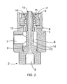
Figure 2 is a schematic cross-sectional side view of a second moistening nozzle of a paper web, and -
Figure 3 is a schematic cross-sectional side view of a third moistening nozzle of a paper web. - For the sake of clarity some embodiments of the invention are depicted simplified in the figures. Like reference numerals refer to like parts in the figures.
-
Figure 1 shows a moistening nozzle having a frame 1. Inside the frame 1 there is arranged awater nozzle 2. Arear part 2b of thewater nozzle 2 is connected to the inside of the frame 1 with a threadedjoint 12. Further, inside the frame 1 there is arranged a threadedpiece 3 of an air nozzle such that thewater nozzle 2 and the threadedpiece 3 are concentric. The threadedpiece 3 is secured to the frame 1 with an airnozzle sleeve part 4 that is connected to the exterior of the frame 1 with a threadedjoint 13. - The
water nozzle 2 includes awater connector 5, into which water is fed with a pipe or a hose or the like. Thewater connector 5 comprises, for instance, a thread for connecting the pipe or the hose. From thewater connector 5 the water flows through awater duct 6 out of the water nozzle. In the frame 1 there is arranged anair connector 7, to which a pipe or a hose or the like is connected with a threaded joint, for instance, for feeding air to the moistening nozzle. The water is fed into the moistening nozzle, i.e. in the middle of the moistening nozzle, from the rear part thereof, and the air is fed to the moistening nozzle from the side of the moistening nozzle. - From the
air connector 7 the air is conducted to anair chamber 8 that is arranged around ashaft 14 of the water nozzle. From theair chamber 8 the air flows throughapertures 9 in the frame 1 towards the threadedpiece 3. - The threaded
piece 3 comprises aninternal thread 10 which is provided on the inner surface of the threadedpiece 3 and by which the air is brought to swirling motion. The air in swirling motion thus flows through anair gap 15 in the moistening nozzle to surround the water from thewater nozzle 2, whereby the mixture of water and air form water mist. Thanks to the swirling motion the water mist forms an even cone-shaped spray. - The threaded
piece 3 is arranged inside the frame 1 such that the threaded piece is positioned into place against acontrol surface 11 of the air nozzle inside the frame 1. Thecontrol surface 11 of the air nozzle is located around the central axis of the moistening nozzle in the circumferential direction. - Between the different pieces of the moistening nozzle it is possible to arrange seals in necessary places. The seals may be O-ring seals of EPDM rubber, for instance.
- The threaded
piece 3 is advantageously provided by moulding it in one piece. If desired, the threadedpiece 3 may also consist of several pieces. The threadedpiece 3 can be made of plastic or another material suitable for moulding, for instance, by injection moulding. The plastic material should be such that it does not absorb water and resists heat at least 180 °C, for instance. One plastic grade suitable for the purpose is polyethersulphone PES. - When the threaded
piece 3 Is manufactured by moulding, it is relatively easy to make air nozzles withvarious threads 10, for Instance. Thus, by changing the threaded piece in the moistening nozzle it is possible to provide various spray patterns. Further, the depth of thread may vary in the desired manner. Other parts of the moistening nozzle may be made of steel, for instance. - in
Figure 1 thewater nozzle 2 consists of two pieces. Thetip part 2a of the water nozzle, i.e. the nozzle pipe, is provided to form an integral part of the nozzle frame 1. Thus thetip part 2a of the water nozzle and acontrol surface 11 of the air nozzle can be machined in the same machining step and with one attachment of the machining tool. In this manner it is possible to set the threadedpiece 3 and thetip part 2a of the water nozzle very accurately into place with respect to one another, which ensures a very good and even spray. Thanks to the structure it is also very easy to assemble the nozzle cornectly and the dimensional accuracy of theair gap 15 will be retained as the moistening nozzle ages. - The
rear part 2b of the water nozzle, i.e. a hollow conductor, is a separate piece and it is secured to the frame 1 with a threaded joint 12. The tolerances in the interconnection of therear part 2b of the water nozzle and the frame 1 need not be very accurate, but nevertheless the moistening nozzle produces an even spray. It will suffice that therear part 2b of the water nozzle is tightly secured to the frame 1 such that the water runs smoothly through thewater duct 6. If desired, thewater nozzle 2 in the whole could be made to form an integral part of the nozzle frame 1, but for instance, when the moistening nozzle is made of metal the manufacturing of a piece by machining is considerably easier if therear part 2b of the water nozzle is a separate piece that is secured to the frame 1. - The middle portion of the
sleeve part 4 extends to the vicinity of thetip part 2a of the water nozzle. The dimensions of thetip part 2a of the water nozzle and thesleeve part 4 determine the size and shape of theair gap 15 outside thewater nozzle 2. The size and shape of theair gap 15 have a considerable effect on the operation of the nozzle. Advantageously theair gap 15 is ring-shaped and concentric with thewater nozzle 2, but it may also have some other shape. On the outer surface of the frame 1 there is acontrol surface 16 of the sleeve part. Thecontrol surface 16 of the sleeve part is around the central axis of the moistening nozzle in the circumferential direction. By means of thecontrol surface 16 thesleeve part 4 is positioned into place. As thetip part 2a of the water nozzle, the threaded joint 13 and thecontrol surface 16 of the sleeve part can be machined in the same machining step and with one attachment of the machining tool, thetip part 2a of the water nozzle and thesleeve part 4 can be mutually mounted into place with great accuracy. Consequently, theair gap 15 between thetip part 2a and thesleeve part 4 can be formed with great accuracy to have a desired shape, which ensures very good and even spray. Thanks to the structure it is also very easy to assemble the nozzle correctly and the dimensional accuracy of theair gap 15 will be retained as the moistening nozzle ages. - Advantageously the threaded
piece 3 is manufactured by moulding into one piece. Moulding within the limits of the dimensional accuracy requirements set for the threadedpiece 3 is relatively difficult, however. Instead, when thesleeve part 4 is made of metal by machining, the dimensions thereof will be accurate. In addition, when thesleeve part 4 is arranged in the above-described manner accurately concentric with thetip part 2a of the water nozzle, theair gap 15 will be provided to have precisely the desired shape, and consequently the function of the threadedpiece 3 is just to bring the air into swirling motion. - In the moistening nozzle of
Figure 2 the inner edge of theair gap 15 is formed by a rod-shaped middle portion of the moistening nozzle. This rod-shaped middle portion is hollow and thewater nozzle 2 is arranged inside it. In the moistening nozzle ofFigure 2 the rear part and the tip part of the water nozzle are provided to be an integral part. - The moistening nozzle of
Figure 2 also differs from that ofFigure 1 as regards thesleeve part 4. In the moistening nozzle ofFigure 2 thesleeve part 4 is a plate with an aperture in the middle. InFigure 2 thesleeve part 4 is positioned accurately into place by means of conical surfaces. Thesleeve part 4 may thus be secured to the frame 1, for instance, by a welded or glued joint, or by means of a separate tightening screw. - In the embodiment of
Figure 3 the tip of thewater nozzle 2 ends on the level of the lower surface of thesleeve part 4. In some embodiment the tip may also end below thesleeve part 4. The part of the frame 1 forming the inner edge of theair gap 15 may extend above thesleeve part 4 as is shown in the attached figures. In some embodiments said part may also end on the level of the upper part of thesleeve part 4 or even on the level of the lower part thereof. - Further, in the embodiment of
Figure 3 there is arranged anauxiliary duct 17 between the tip of thewater nozzle 2 and the frame 1. Theauxiliary duct 17 provides another passage for air, whereby the moistening nozzle forms two air sprays one within the other. Theauxiliary duct 17 may be straight or it may be provided with means for bringing the air into swirling motion. The air may be brought to swirl in the same or in the opposite direction with the air in the outer air spray. Thus the thread, spoilers or grooves in theauxiliary duct 17 may be arranged at an angle of 0 to 180 degrees in relation to the longitudinal axis of the auxiliary duct. - Also, in the embodiment of
Figure 3 , because the tip of thewater nozzle 2 ends before the tip of the middle part of the frame 1, in the moistening nozzle there is first formed a supplementary air spray and thereafter another air spray from theair gap 15. - Air pressure of the air constituting the auxiliary air spray may be arranged different from that of the air spray discharging from the
air gap 15 by choking the airflows. Thus the relation between the cross sectional surfaces of theapertures 9 and theauxiliary duct 17 determines said difference in pressure. Thus, in a given moistening nozzle structure the pressure difference remains substantially constant. It is also possible to arrange two separate air intakes in the moistening nozzle, whereby air is fed in theapertures 9 from a first air source and air is fed in theauxiliary duct 17 from a second air source. Hence, the air pressures in moistening nozzle parts producing different air sprays can be adjusted as desired. - In some cases the features set forth in this document can be used as such, irrespective of other features. On the other hand, when necessary, the features set forth in this document can be combined to provide various combinations.
- The drawings and the relating description are only intended to illustrate the inventive idea. The details of the invention may vary within the scope of the claims. Thus, for instance, the
threads 10 provided in the threadedpart 3 can be formed to make the air spray swirl clockwise or anticlockwise. On the other hand, it is also possible to manufacture some of the moistening nozzles such that the spray swirls clockwise and others such that the air spray swirls anticlockwise. In that case some of the moistening nozzles can be mounted on the moistening apparatus such that the spray swirls clockwise and others such that the air spray swirls anticlockwise, and consequently a homogeneous moistening response can be achieved in the moistening apparatus by altering the construction of the nozzle. - The threaded piece may also be provided such that it comprises an external thread. The threaded piece may also be provided such that it has a continuous outer and inner surface and the thread that brings the airflow into swirling motion is provided inside the threaded piece, i.e. such that the threaded piece comprises a helical duct.
- Instead of the
thread 10, the means in connection with the air nozzle, by which the air is brought into swirling motion, may consist of successive spoilers. - Further, it is possible to combine the water nozzle and the air nozzle by providing the threads or spoilers, which bring the airflow into swirling motion, directly on the exterior of the water nozzle or by drilling air ducts in the water nozzle. The threads or the spoilers may also be provided directly on the inner or outer surface, or both, of the middle part of the frame. If desired, the threaded piece may be provided to be an integral part of the frame. Yet instead of threaded joints it is possible to use, for instance, welded or glued joints or other joints suitable for the purpose in the moistening nozzle.
Claims (12)
- A moistening nozzle of a paper web comprising a frame (1) to which air can be fed, a water nozzle (2) arranged inside the frame (1) to which water can be fed and to conduct water out of the moistening nozzle and an air nozzle to conduct air out of the moistening nozzle, and in connection with the air nozzle there are threads (10) or successive spoilers by which the air is brought into swirling motion and which are arranged in a threaded piece (3), which is arranged inside the frame (1) such that the water nozzle (2) and the threaded piece (3) are concentric, the air nozzle and the water nozzle (2) are arranged one within the other to allow the air and the water to produce water mist that is sprayed out from the moistening nozzle, in the air nozzle comprises a sleeve part (4) having an opening through which the air is conducted out from the moistening nozzle, a piece is arranged in a centralized manner with said opening, whereby said piece and the sleeve part (4) form an air gap (15), wherein the piece is an integral part of the moistening nozzle frame (1), and forms an inner edge of said air gap (15).
- A moistening nozzle as claimed in claim 1, characterized in that a tip part (2a) of the water nozzle (2) is an integral part of the frame (1) such that the tip part (2a) of the water nozzle (2) forms the inner edge of the air gap (15).
- A moistening nozzle as claimed in claim 2, characterized in that a rear part (2b) of the water nozzle (2) is provided to be a separate piece from the tip part (2a).
- A moistening nozzle as claimed in claim 1, characterized in that a rod-like middle part of the moistening nozzle frame (1) forms the inner edge of said air gap (15), within which middle part there is arranged the tip of the water nozzle (2).
- A moistening nozzle of a paper web as claimed in any one of the preceding claims, characterized in that the air is brought into swirling motion by said threads (10) which are formed by the threaded piece (3) provided with an internal thread (10).
- A moistening nozzle of a paper web as claimed in claim 5, characterized in that inside the frame (1) there is a control surface (11) of the air nozzle, to which the outer surface of the threaded piece (3) is supported.
- A moistening nozzle of a paper web as claimed in claim 6, characterized in that the control surface (11) of the air nozzle is in the direction of the circumference around the central axis of the moistening nozzle.
- A moistening nozzle of a paper web as claimed in any one of claims 5 to 7, characterized in that the threaded piece (3) is a moulded piece.
- A moistening nozzle of a paper web as claimed in claim 8, characterized in that the threaded piece (3) is made of plastic.
- A moistening nozzle of a paper web as claimed in any one of claims 5 to 9, characterized in that the threaded piece (3) is arranged into place by means of the sleeve part (4).
- A moistening nozzle of a paper web as claimed in claim 10, characterized in that on the outer surface of the frame (1) there is a control surface (16) of the sleeve part, to which the inner surface of the sleeve part (4) is supported.
- A moistening nozzle of a paper web as claimed in claim 11, characterized in that the control surface (16) of the sleeve part (4) is in the direction of the circumference around the central axis of the moistening nozzle.
Applications Claiming Priority (2)
| Application Number | Priority Date | Filing Date | Title |
|---|---|---|---|
| FI20055394A FI20055394A0 (en) | 2005-07-07 | 2005-07-07 | Paper path wetting nozzle |
| PCT/FI2006/050320 WO2007006861A1 (en) | 2005-07-07 | 2006-07-06 | Moistening nozzle of a paper web |
Publications (3)
| Publication Number | Publication Date |
|---|---|
| EP1904239A1 EP1904239A1 (en) | 2008-04-02 |
| EP1904239A4 EP1904239A4 (en) | 2011-08-31 |
| EP1904239B1 true EP1904239B1 (en) | 2013-12-25 |
Family
ID=34803263
Family Applications (1)
| Application Number | Title | Priority Date | Filing Date |
|---|---|---|---|
| EP06764554.9A Active EP1904239B1 (en) | 2005-07-07 | 2006-07-06 | Moistening nozzle of a paper web |
Country Status (6)
| Country | Link |
|---|---|
| US (1) | US8393555B2 (en) |
| EP (1) | EP1904239B1 (en) |
| CA (1) | CA2614258A1 (en) |
| ES (1) | ES2453541T3 (en) |
| FI (1) | FI20055394A0 (en) |
| WO (1) | WO2007006861A1 (en) |
Families Citing this family (4)
| Publication number | Priority date | Publication date | Assignee | Title |
|---|---|---|---|---|
| EP2808087B1 (en) | 2013-05-28 | 2019-02-27 | Valmet Technologies, Inc. | Device for treating a fibre web |
| ITRM20130562A1 (en) * | 2013-10-11 | 2015-04-12 | Manuele Casale | DISTRIBUTION DEVICE FOR A SUBSTANCE IN THE FORM OF AEROSOL |
| JP7145469B2 (en) * | 2018-03-05 | 2022-10-03 | 国立大学法人東京工業大学 | Injection nozzle and injection device using the same |
| WO2023061799A1 (en) | 2021-10-11 | 2023-04-20 | Basf Se | Atomizer nozzle |
Family Cites Families (15)
| Publication number | Priority date | Publication date | Assignee | Title |
|---|---|---|---|---|
| US1474603A (en) * | 1919-12-31 | 1923-11-20 | Albert W Morse | Liquid and gas mixer |
| US1609841A (en) * | 1923-03-14 | 1926-12-07 | Joseph J Smith | Humidifying or air-moistening apparatus |
| DE952765C (en) | 1954-03-16 | 1957-04-04 | V I B Appbau Ges M B H | Device for atomizing and applying liquid media to dry fibrous material, especially paper webs |
| US3375978A (en) * | 1966-03-21 | 1968-04-02 | Rand Mines Ltd | Spray gun with self-purging nozzle |
| DE1660592B2 (en) * | 1967-12-09 | 1975-01-23 | Plutte, Koecke & Co, 5600 Wuppertal | Blow jet nozzle for conveying and / or treating textile thread structures |
| US4453542A (en) | 1980-12-08 | 1984-06-12 | Vortran Corporation | Vortex-generating medical products |
| DE3819762A1 (en) | 1988-06-10 | 1989-12-14 | Vib Apparatebau Gmbh | SPRAY HEAD FOR NOZZLE HUMIDIFIER AND METHOD FOR HUMIDIFYING |
| DE4038191A1 (en) | 1990-11-30 | 1992-08-20 | Peter Loerincz | Double duct nozzle for burner - has second duct in form of cone which surrounds first duct |
| US5292068A (en) | 1992-08-17 | 1994-03-08 | Nordson Corporation | One-piece, zero cavity nozzle for swirl spray of adhesive |
| US5697553A (en) | 1995-03-03 | 1997-12-16 | Parker-Hannifin Corporation | Streaked spray nozzle for enhanced air/fuel mixing |
| US5692682A (en) * | 1995-09-08 | 1997-12-02 | Bete Fog Nozzle, Inc. | Flat fan spray nozzle |
| EP0904844A4 (en) * | 1996-06-10 | 2005-08-31 | Nippon Telegraph & Telephone | Two-fluid nozzle and device employing the same nozzle for freezing and drying liquid containing biological substances |
| DE19730617A1 (en) | 1997-07-17 | 1999-01-21 | Abb Research Ltd | Pressure atomizer nozzle |
| US6036116A (en) * | 1998-04-16 | 2000-03-14 | Coltec Industries Inc | Fluid atomizing fan spray nozzle |
| DE19949236C2 (en) | 1999-10-13 | 2003-05-08 | Lechler Gmbh & Co Kg | Two-component spray nozzle |
-
2005
- 2005-07-07 FI FI20055394A patent/FI20055394A0/en not_active Application Discontinuation
-
2006
- 2006-07-06 ES ES06764554.9T patent/ES2453541T3/en active Active
- 2006-07-06 WO PCT/FI2006/050320 patent/WO2007006861A1/en active Application Filing
- 2006-07-06 US US11/988,373 patent/US8393555B2/en not_active Expired - Fee Related
- 2006-07-06 EP EP06764554.9A patent/EP1904239B1/en active Active
- 2006-07-06 CA CA002614258A patent/CA2614258A1/en not_active Abandoned
Also Published As
| Publication number | Publication date |
|---|---|
| FI20055394A0 (en) | 2005-07-07 |
| CA2614258A1 (en) | 2007-01-18 |
| WO2007006861A1 (en) | 2007-01-18 |
| US20090057439A1 (en) | 2009-03-05 |
| EP1904239A1 (en) | 2008-04-02 |
| EP1904239A4 (en) | 2011-08-31 |
| US8393555B2 (en) | 2013-03-12 |
| ES2453541T3 (en) | 2014-04-08 |
Similar Documents
| Publication | Publication Date | Title |
|---|---|---|
| US10245602B2 (en) | Atomizer nozzle | |
| US6997405B2 (en) | External mix air atomizing spray nozzle assembly | |
| US6705538B2 (en) | Two-medium spraying nozzle and method of using same | |
| JP4902062B2 (en) | Improved pneumatic spray nozzle | |
| US5072883A (en) | Full cone spray nozzle with external air atomization | |
| US7820011B2 (en) | Moistening nozzle of a paper web | |
| EP1904239B1 (en) | Moistening nozzle of a paper web | |
| US20050284957A1 (en) | External mix air atomizing spray nozzle assembly | |
| MX2015002057A (en) | Full cone air-assisted spray nozzle assembly. | |
| CN108367304A (en) | The full cone spray nozzle assemblies of forced air auxiliary | |
| CN101410188A (en) | Spray gun | |
| CN104624423A (en) | Bubble atomizing nozzle and adjusting method of bubble atomizing nozzle | |
| CN106499559A (en) | Double oil circuit swirl atomizer structures of major-minor oil circuit integrated design | |
| CN110918284A (en) | Medium atomizing nozzle, spraying device and spraying machine | |
| CN201257412Y (en) | Sprayer | |
| CN207872430U (en) | A kind of fine humidification nozzle | |
| CN114682410A (en) | Spraying device with multiple mixing cavities | |
| CN112254125B (en) | Spiral-flow type pressure atomizing nozzle | |
| CN104624422B (en) | A kind of new three fluid ejectors and spray method | |
| CN109681866A (en) | A kind of cracking burner spray head | |
| CN207086162U (en) | A kind of glue spraying spray gun | |
| RU2435103C1 (en) | Ash collector with swirl atomisers | |
| CN212663928U (en) | Spray gun with metal hose | |
| CN211587114U (en) | Nozzle applied to paint spray gun | |
| CN213855159U (en) | Atomizing nozzle structure of temperature reducing device |
Legal Events
| Date | Code | Title | Description |
|---|---|---|---|
| PUAI | Public reference made under article 153(3) epc to a published international application that has entered the european phase |
Free format text: ORIGINAL CODE: 0009012 |
|
| 17P | Request for examination filed |
Effective date: 20080131 |
|
| AK | Designated contracting states |
Kind code of ref document: A1 Designated state(s): AT BE BG CH CY CZ DE DK EE ES FI FR GB GR HU IE IS IT LI LT LU LV MC NL PL PT RO SE SI SK TR |
|
| DAX | Request for extension of the european patent (deleted) | ||
| A4 | Supplementary search report drawn up and despatched |
Effective date: 20110728 |
|
| RIC1 | Information provided on ipc code assigned before grant |
Ipc: D21G 7/00 20060101ALI20110722BHEP Ipc: B05B 1/34 20060101ALI20110722BHEP Ipc: B05B 7/10 20060101AFI20110722BHEP |
|
| DAX | Request for extension of the european patent (deleted) | ||
| 17Q | First examination report despatched |
Effective date: 20120713 |
|
| GRAP | Despatch of communication of intention to grant a patent |
Free format text: ORIGINAL CODE: EPIDOSNIGR1 |
|
| INTG | Intention to grant announced |
Effective date: 20130724 |
|
| RIN1 | Information on inventor provided before grant (corrected) |
Inventor name: POSTI, NIKO Inventor name: ALMI, JARI Inventor name: NIEMELAE, HANNU |
|
| GRAS | Grant fee paid |
Free format text: ORIGINAL CODE: EPIDOSNIGR3 |
|
| GRAA | (expected) grant |
Free format text: ORIGINAL CODE: 0009210 |
|
| RAP1 | Party data changed (applicant data changed or rights of an application transferred) |
Owner name: METSO AUTOMATION OY |
|
| AK | Designated contracting states |
Kind code of ref document: B1 Designated state(s): AT BE BG CH CY CZ DE DK EE ES FI FR GB GR HU IE IS IT LI LT LU LV MC NL PL PT RO SE SI SK TR |
|
| REG | Reference to a national code |
Ref country code: GB Ref legal event code: FG4D |
|
| REG | Reference to a national code |
Ref country code: CH Ref legal event code: EP |
|
| REG | Reference to a national code |
Ref country code: AT Ref legal event code: REF Ref document number: 646293 Country of ref document: AT Kind code of ref document: T Effective date: 20140115 |
|
| REG | Reference to a national code |
Ref country code: IE Ref legal event code: FG4D |
|
| REG | Reference to a national code |
Ref country code: DE Ref legal event code: R096 Ref document number: 602006039792 Country of ref document: DE Effective date: 20140213 |
|
| REG | Reference to a national code |
Ref country code: ES Ref legal event code: FG2A Ref document number: 2453541 Country of ref document: ES Kind code of ref document: T3 Effective date: 20140408 |
|
| REG | Reference to a national code |
Ref country code: SE Ref legal event code: TRGR |
|
| PG25 | Lapsed in a contracting state [announced via postgrant information from national office to epo] |
Ref country code: LT Free format text: LAPSE BECAUSE OF FAILURE TO SUBMIT A TRANSLATION OF THE DESCRIPTION OR TO PAY THE FEE WITHIN THE PRESCRIBED TIME-LIMIT Effective date: 20131225 |
|
| REG | Reference to a national code |
Ref country code: NL Ref legal event code: VDEP Effective date: 20131225 |
|
| REG | Reference to a national code |
Ref country code: AT Ref legal event code: MK05 Ref document number: 646293 Country of ref document: AT Kind code of ref document: T Effective date: 20131225 |
|
| REG | Reference to a national code |
Ref country code: LT Ref legal event code: MG4D |
|
| PG25 | Lapsed in a contracting state [announced via postgrant information from national office to epo] |
Ref country code: LV Free format text: LAPSE BECAUSE OF FAILURE TO SUBMIT A TRANSLATION OF THE DESCRIPTION OR TO PAY THE FEE WITHIN THE PRESCRIBED TIME-LIMIT Effective date: 20131225 |
|
| PG25 | Lapsed in a contracting state [announced via postgrant information from national office to epo] |
Ref country code: BE Free format text: LAPSE BECAUSE OF FAILURE TO SUBMIT A TRANSLATION OF THE DESCRIPTION OR TO PAY THE FEE WITHIN THE PRESCRIBED TIME-LIMIT Effective date: 20131225 Ref country code: EE Free format text: LAPSE BECAUSE OF FAILURE TO SUBMIT A TRANSLATION OF THE DESCRIPTION OR TO PAY THE FEE WITHIN THE PRESCRIBED TIME-LIMIT Effective date: 20131225 Ref country code: IS Free format text: LAPSE BECAUSE OF FAILURE TO SUBMIT A TRANSLATION OF THE DESCRIPTION OR TO PAY THE FEE WITHIN THE PRESCRIBED TIME-LIMIT Effective date: 20140425 |
|
| PG25 | Lapsed in a contracting state [announced via postgrant information from national office to epo] |
Ref country code: NL Free format text: LAPSE BECAUSE OF FAILURE TO SUBMIT A TRANSLATION OF THE DESCRIPTION OR TO PAY THE FEE WITHIN THE PRESCRIBED TIME-LIMIT Effective date: 20131225 Ref country code: SK Free format text: LAPSE BECAUSE OF FAILURE TO SUBMIT A TRANSLATION OF THE DESCRIPTION OR TO PAY THE FEE WITHIN THE PRESCRIBED TIME-LIMIT Effective date: 20131225 Ref country code: CZ Free format text: LAPSE BECAUSE OF FAILURE TO SUBMIT A TRANSLATION OF THE DESCRIPTION OR TO PAY THE FEE WITHIN THE PRESCRIBED TIME-LIMIT Effective date: 20131225 Ref country code: CY Free format text: LAPSE BECAUSE OF FAILURE TO SUBMIT A TRANSLATION OF THE DESCRIPTION OR TO PAY THE FEE WITHIN THE PRESCRIBED TIME-LIMIT Effective date: 20131225 Ref country code: PL Free format text: LAPSE BECAUSE OF FAILURE TO SUBMIT A TRANSLATION OF THE DESCRIPTION OR TO PAY THE FEE WITHIN THE PRESCRIBED TIME-LIMIT Effective date: 20131225 Ref country code: PT Free format text: LAPSE BECAUSE OF FAILURE TO SUBMIT A TRANSLATION OF THE DESCRIPTION OR TO PAY THE FEE WITHIN THE PRESCRIBED TIME-LIMIT Effective date: 20140428 Ref country code: RO Free format text: LAPSE BECAUSE OF FAILURE TO SUBMIT A TRANSLATION OF THE DESCRIPTION OR TO PAY THE FEE WITHIN THE PRESCRIBED TIME-LIMIT Effective date: 20131225 Ref country code: AT Free format text: LAPSE BECAUSE OF FAILURE TO SUBMIT A TRANSLATION OF THE DESCRIPTION OR TO PAY THE FEE WITHIN THE PRESCRIBED TIME-LIMIT Effective date: 20131225 |
|
| REG | Reference to a national code |
Ref country code: DE Ref legal event code: R097 Ref document number: 602006039792 Country of ref document: DE |
|
| PG25 | Lapsed in a contracting state [announced via postgrant information from national office to epo] |
Ref country code: DK Free format text: LAPSE BECAUSE OF FAILURE TO SUBMIT A TRANSLATION OF THE DESCRIPTION OR TO PAY THE FEE WITHIN THE PRESCRIBED TIME-LIMIT Effective date: 20131225 |
|
| PLBE | No opposition filed within time limit |
Free format text: ORIGINAL CODE: 0009261 |
|
| STAA | Information on the status of an ep patent application or granted ep patent |
Free format text: STATUS: NO OPPOSITION FILED WITHIN TIME LIMIT |
|
| 26N | No opposition filed |
Effective date: 20140926 |
|
| REG | Reference to a national code |
Ref country code: DE Ref legal event code: R097 Ref document number: 602006039792 Country of ref document: DE Effective date: 20140926 |
|
| PG25 | Lapsed in a contracting state [announced via postgrant information from national office to epo] |
Ref country code: LU Free format text: LAPSE BECAUSE OF FAILURE TO SUBMIT A TRANSLATION OF THE DESCRIPTION OR TO PAY THE FEE WITHIN THE PRESCRIBED TIME-LIMIT Effective date: 20140706 |
|
| REG | Reference to a national code |
Ref country code: CH Ref legal event code: PL |
|
| GBPC | Gb: european patent ceased through non-payment of renewal fee |
Effective date: 20140706 |
|
| REG | Reference to a national code |
Ref country code: IE Ref legal event code: MM4A |
|
| PG25 | Lapsed in a contracting state [announced via postgrant information from national office to epo] |
Ref country code: LI Free format text: LAPSE BECAUSE OF NON-PAYMENT OF DUE FEES Effective date: 20140731 Ref country code: CH Free format text: LAPSE BECAUSE OF NON-PAYMENT OF DUE FEES Effective date: 20140731 |
|
| PG25 | Lapsed in a contracting state [announced via postgrant information from national office to epo] |
Ref country code: GB Free format text: LAPSE BECAUSE OF NON-PAYMENT OF DUE FEES Effective date: 20140706 Ref country code: SI Free format text: LAPSE BECAUSE OF FAILURE TO SUBMIT A TRANSLATION OF THE DESCRIPTION OR TO PAY THE FEE WITHIN THE PRESCRIBED TIME-LIMIT Effective date: 20131225 |
|
| PG25 | Lapsed in a contracting state [announced via postgrant information from national office to epo] |
Ref country code: IE Free format text: LAPSE BECAUSE OF NON-PAYMENT OF DUE FEES Effective date: 20140706 |
|
| PG25 | Lapsed in a contracting state [announced via postgrant information from national office to epo] |
Ref country code: MC Free format text: LAPSE BECAUSE OF FAILURE TO SUBMIT A TRANSLATION OF THE DESCRIPTION OR TO PAY THE FEE WITHIN THE PRESCRIBED TIME-LIMIT Effective date: 20131225 |
|
| PG25 | Lapsed in a contracting state [announced via postgrant information from national office to epo] |
Ref country code: BG Free format text: LAPSE BECAUSE OF FAILURE TO SUBMIT A TRANSLATION OF THE DESCRIPTION OR TO PAY THE FEE WITHIN THE PRESCRIBED TIME-LIMIT Effective date: 20131225 |
|
| PG25 | Lapsed in a contracting state [announced via postgrant information from national office to epo] |
Ref country code: IT Free format text: LAPSE BECAUSE OF FAILURE TO SUBMIT A TRANSLATION OF THE DESCRIPTION OR TO PAY THE FEE WITHIN THE PRESCRIBED TIME-LIMIT Effective date: 20131225 Ref country code: GR Free format text: LAPSE BECAUSE OF FAILURE TO SUBMIT A TRANSLATION OF THE DESCRIPTION OR TO PAY THE FEE WITHIN THE PRESCRIBED TIME-LIMIT Effective date: 20140326 |
|
| REG | Reference to a national code |
Ref country code: FR Ref legal event code: PLFP Year of fee payment: 11 |
|
| PG25 | Lapsed in a contracting state [announced via postgrant information from national office to epo] |
Ref country code: HU Free format text: LAPSE BECAUSE OF FAILURE TO SUBMIT A TRANSLATION OF THE DESCRIPTION OR TO PAY THE FEE WITHIN THE PRESCRIBED TIME-LIMIT; INVALID AB INITIO Effective date: 20060706 Ref country code: TR Free format text: LAPSE BECAUSE OF FAILURE TO SUBMIT A TRANSLATION OF THE DESCRIPTION OR TO PAY THE FEE WITHIN THE PRESCRIBED TIME-LIMIT Effective date: 20131225 |
|
| REG | Reference to a national code |
Ref country code: FR Ref legal event code: PLFP Year of fee payment: 12 |
|
| REG | Reference to a national code |
Ref country code: FR Ref legal event code: PLFP Year of fee payment: 13 |
|
| PGFP | Annual fee paid to national office [announced via postgrant information from national office to epo] |
Ref country code: DE Payment date: 20180723 Year of fee payment: 13 Ref country code: FR Payment date: 20180725 Year of fee payment: 13 Ref country code: ES Payment date: 20180829 Year of fee payment: 13 |
|
| REG | Reference to a national code |
Ref country code: DE Ref legal event code: R119 Ref document number: 602006039792 Country of ref document: DE |
|
| PG25 | Lapsed in a contracting state [announced via postgrant information from national office to epo] |
Ref country code: DE Free format text: LAPSE BECAUSE OF NON-PAYMENT OF DUE FEES Effective date: 20200201 |
|
| PG25 | Lapsed in a contracting state [announced via postgrant information from national office to epo] |
Ref country code: FR Free format text: LAPSE BECAUSE OF NON-PAYMENT OF DUE FEES Effective date: 20190731 |
|
| REG | Reference to a national code |
Ref country code: ES Ref legal event code: FD2A Effective date: 20201126 |
|
| PG25 | Lapsed in a contracting state [announced via postgrant information from national office to epo] |
Ref country code: ES Free format text: LAPSE BECAUSE OF NON-PAYMENT OF DUE FEES Effective date: 20190707 |
|
| PGFP | Annual fee paid to national office [announced via postgrant information from national office to epo] |
Ref country code: FI Payment date: 20230719 Year of fee payment: 18 |
|
| PGFP | Annual fee paid to national office [announced via postgrant information from national office to epo] |
Ref country code: SE Payment date: 20230719 Year of fee payment: 18 |