EP1903683B1 - Range compression in oversampling analog-to-digital converters - Google Patents
Range compression in oversampling analog-to-digital converters Download PDFInfo
- Publication number
- EP1903683B1 EP1903683B1 EP07111882A EP07111882A EP1903683B1 EP 1903683 B1 EP1903683 B1 EP 1903683B1 EP 07111882 A EP07111882 A EP 07111882A EP 07111882 A EP07111882 A EP 07111882A EP 1903683 B1 EP1903683 B1 EP 1903683B1
- Authority
- EP
- European Patent Office
- Prior art keywords
- signal
- range
- sampling
- converter
- digital
- Prior art date
- Legal status (The legal status is an assumption and is not a legal conclusion. Google has not performed a legal analysis and makes no representation as to the accuracy of the status listed.)
- Ceased
Links
- 230000006835 compression Effects 0.000 title claims description 48
- 238000007906 compression Methods 0.000 title claims description 48
- 238000005070 sampling Methods 0.000 claims description 111
- 238000006243 chemical reaction Methods 0.000 claims description 45
- 238000000034 method Methods 0.000 claims description 18
- 239000003990 capacitor Substances 0.000 description 31
- 101000941450 Lasioglossum laticeps Lasioglossin-1 Proteins 0.000 description 7
- 238000009825 accumulation Methods 0.000 description 6
- 238000013139 quantization Methods 0.000 description 6
- 238000010586 diagram Methods 0.000 description 5
- 238000012546 transfer Methods 0.000 description 5
- 230000001419 dependent effect Effects 0.000 description 4
- 239000000243 solution Substances 0.000 description 4
- 238000012986 modification Methods 0.000 description 3
- 230000004048 modification Effects 0.000 description 3
- 238000002347 injection Methods 0.000 description 2
- 239000007924 injection Substances 0.000 description 2
- 238000005259 measurement Methods 0.000 description 2
- 230000003071 parasitic effect Effects 0.000 description 2
- 230000001960 triggered effect Effects 0.000 description 2
- 238000013461 design Methods 0.000 description 1
- 230000000694 effects Effects 0.000 description 1
- 238000013507 mapping Methods 0.000 description 1
Images


Classifications
-
- H—ELECTRICITY
- H03—ELECTRONIC CIRCUITRY
- H03M—CODING; DECODING; CODE CONVERSION IN GENERAL
- H03M3/00—Conversion of analogue values to or from differential modulation
- H03M3/30—Delta-sigma modulation
- H03M3/458—Analogue/digital converters using delta-sigma modulation as an intermediate step
- H03M3/478—Means for controlling the correspondence between the range of the input signal and the range of signals the converter can handle; Means for out-of-range indication
- H03M3/488—Means for controlling the correspondence between the range of the input signal and the range of signals the converter can handle; Means for out-of-range indication using automatic control
- H03M3/49—Means for controlling the correspondence between the range of the input signal and the range of signals the converter can handle; Means for out-of-range indication using automatic control in feedback mode, i.e. by determining the range to be selected from one or more previous digital output values
-
- H—ELECTRICITY
- H03—ELECTRONIC CIRCUITRY
- H03M—CODING; DECODING; CODE CONVERSION IN GENERAL
- H03M3/00—Conversion of analogue values to or from differential modulation
- H03M3/30—Delta-sigma modulation
- H03M3/39—Structural details of delta-sigma modulators, e.g. incremental delta-sigma modulators
- H03M3/412—Structural details of delta-sigma modulators, e.g. incremental delta-sigma modulators characterised by the number of quantisers and their type and resolution
- H03M3/422—Structural details of delta-sigma modulators, e.g. incremental delta-sigma modulators characterised by the number of quantisers and their type and resolution having one quantiser only
- H03M3/43—Structural details of delta-sigma modulators, e.g. incremental delta-sigma modulators characterised by the number of quantisers and their type and resolution having one quantiser only the quantiser being a single bit one
-
- H—ELECTRICITY
- H03—ELECTRONIC CIRCUITRY
- H03M—CODING; DECODING; CODE CONVERSION IN GENERAL
- H03M3/00—Conversion of analogue values to or from differential modulation
- H03M3/30—Delta-sigma modulation
- H03M3/39—Structural details of delta-sigma modulators, e.g. incremental delta-sigma modulators
- H03M3/436—Structural details of delta-sigma modulators, e.g. incremental delta-sigma modulators characterised by the order of the loop filter, e.g. error feedback type
- H03M3/456—Structural details of delta-sigma modulators, e.g. incremental delta-sigma modulators characterised by the order of the loop filter, e.g. error feedback type the modulator having a first order loop filter in the feedforward path
Definitions
- the input signal range of an Analog-to-Digital converter extends between a minimum value (further referred to as the "input range lower limit” LL) and a maximum value (further referred to as the "input range upper limit”
- LL minimum value
- UL maximum value
- the LL usually represents the zero scale point
- the UL usually describes the full-scale point
- the LL is usually the "minus full scale” point while the UL is usually the "plus full scale” point.
- the end points of the ADC external input range -- i.e., the end points of the range of the analog signal transmitted to the ADC -- will be referred to as LL and UL while the end points of the ADC internal input range -- i.e., the end points of the range of signals that the ADC is able to process -- will be referred to as LL I and UL I .
- LL the end points of the ADC external input range
- UL I the end points of the ADC internal input range
- the LL and UL values are in general easily available external signals like "ground” or Vref (reference voltage) or - Vref and are commonly used in evaluating and calibrating the ADC offset and gain errors.
- Vref reference voltage
- - Vref reference voltage
- the presence of internal ADC error sources may result in a combined equivalent value outside of the ADC internal input signal range LL I -to-UL I .
- the conversion produces an "out of range” result.
- the ADC output cannot be calibrated using this result. This is because the result does not contain sufficient meaningful information. Therefore it is highly desirable to use an ADC with an internal range LL I -to-UL I wider than the external range LL-to-UL.
- FIG. 1 A graphical representation of the relations between the external input range, the internal input range and the output range are shown in FIG. 1 .
- Document US 5 187 482 A discloses a delta sigma analog-to-digital converter including a digitally-controlled multiplying digital-to-analog converter in a feedback configuration.
- the converter may comprise an oversampled interpolating modulator.
- Document US 6 140 950 A discloses an oversampling analog-to-digital converter comprising a switched-capacitor subtractor/integrator circuit that provides a desired capacitor ratio by using N+M distinct unit capacitors that each sample an input signal a first predetermined number of times and sample one or more reference signals a second predetermined number of times, where the ratio of the first predetermined number to the second predetermined number is the desired capacitor ratio N/M.
- FIG. 1 is a diagram illustrating an embodiment of an external input range end an expanded internal input or an analog-to-digital converter.
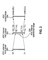
- FIG. 2 is a diagram illustrating a conventional external input range, an internal input range, and a compressed operational range of an analog-to-digital converter.
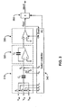
- FIG. 3 is a diagram illustrating an analog-to-digital conversion arrangement according to the present invention.
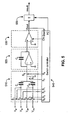
- FIG. 4 is a diagram illustrating another analog-to-digital conversion arrangement for converting a differential analog signal as an example for a better understanding of the invention.
- FIG. 5 is a diagram illustrating another examplary analog-to-digital conversion arrangement not covered by the claims.
- This invention proposes a more efficient solution to the three problems described above. It is quite often the case that these problems occur in a very narrow region near the LL I and UL I values.
- the size of the margins required to compensate for these problems at the LL I and UL I ends of the scale varies usually from a very small fraction of 1% to about 10% of full scale. For an optimal implementation it is thus desirable to be able to adjust the size of these margins with good resolution, repeatability and accuracy.
- FIG. 2 A graphical representation of the proposed relations between the external input range 200, the internal input range 202 and the output range 204 are shown in FIG. 2 . Furthermore, an operational range 206 that has been compressed from the internal input range is also shown.
- the maximum external input signal range LL - UL is compressed into a slightly smaller magnitude operational internal input range LL' - UL' 206 located within the internal maximum input range LL I - UL I .
- the maximum internal input range is approximately equal in size with the maximum external input range such that: LL ′ > LL I ⁇ LL and UL ′ ⁇ UL I ⁇ UL
- the output maximum range code(LL) - code(UL) is obtained by expanding the conversion engine output range code(LL') - code(UL').
- the ADC engine does not need to be over designed. Furthermore, the size of the margins maintained at the internal input range end points LL I and UL I can be precisely controlled by adjusting the input range compression ratio (LL-to-UL into LL'-to-UL') and its reciprocal - the output code expansion ratio (code(LL')-to-code(UL') into cade(LL)-to-cade(UL)).
- V RC LL ⁇ V RC ⁇ UL
- the compression factor resolution (through the ratio N1 / ( N + N1)) is directly dependent upon the oversampling ratio N and can be immediately improved by increasing this ratio.
- N1 / (N + N1) is preferably defined by digital control circuits, additional sources of inaccuracy are attributable solely to V RC . It is therefore desirable to derive V RC directly from the converter input range limit values LL and UL through digital relationships in order to minimize or eliminate additional sources of error.
- V RC 0.5*(LL + UL) can be done by sampling the LL external signal in half of the additional N1 sample periods and sampling the external UL signal in the remaining half. This would be particularly useful in a unipolar converter in which LL is usually ground and UL is usually the external reference voltage V REF .
- V RC value becomes zero and the range compression can be implemented by not sampling any voltage during the N1 additional periods (see FIG. 5 for such an example).
- An alternative implementation samples the -V REF external signal in half of the N1 periods and the +V REF external signal in the remaining half.
- V RC 0.75 * LL + 0.25 * UL as suggested in the second example presented above, one can elect to sample the LL external signal in three quarters of the additional N1 periods and the UL external signal in remaining one quarter of N1.
- the minimum condition for implementing range compression is an over-sampled ADC using N sample periods and having an input range LL-to-UL.
- a range compression signal V RC sampled as input during N1 additional sample periods.
- range compression can be obtained when the average V RC is between LL and UL.
- V RC signal is further desirable to derive the V RC signal from the LL and UL values, preferable through digital controlled relations.
- N R V AV / V REF * N
- the output comparator 330 generates the digital output stream Dout.
- This data stream is used by the switch controller 340 together with an internal clock signal to direct the operation of this first order over-sampling modulator.
- the proposed range compression is implemented within the switch controller 340 which is able to initiate three types of sampling cycles labeled IN, RP and RN.
- An IN-type sampling cycle is performed N times during a conversion operation and consists of sampling the analog input signal V IN .
- the modulator samples the upper reference input signal V RP or the lower reference input signal V RN depending upon the value of the Dout digital signal.
- the switch controller 340 preferably directs the following sequence of events:
- An RP-type sampling cycle is performed 0.5 * N1 times during a conversion operation and consists of sampling the upper reference input signal V RP .
- the modulator samples the upper reference input signal V RP or the lower reference input signal V RN depending upon the value of the Dout digital signal.
- the switch controller 340 directs the following sequence of events:
- the switch controller 340 must perform 2 16 IN-type sampling cycles, 32 RP-type sampling cycles and 32 RN-type sampling cycles during a complete conversion operation.
- the relative position of the RP and RN-type cycles within the IN-type cycles is chosen based upon previously described criteria.
- N 2 16
- the switch controller 340 will direct the succession of IN, RP and RN sampling cycles within one conversion operation as follow: a. Start the conversion operation. b. Set the accumulator within the digital filter 350 to initial value -32 and begin the accumulation of digital data Dout. c. Repeat 32 times the following steps 1 through 5. 1. Perform 512 IN-type cycles 2. Perform 1 RP-type cycle 3. Perform 1024 IN-type cycles 4. Perform 1 RN-type cycle 5. Perform 512 IN-type cycles d. End the accumulation process in filter 350 and output the conversion result e. End the conversion operation
- FIG. 4 An example of a practical implementation not covered by the claims is shown in FIG. 4 .
- the converter receives a differential analog input signal [V IP , V IN ] and a differential analog reference signal [V RP , V RN ].
- the converter produces the digital output "result".
- FIG. 4 includes an input sampling circuit 410, an integrator 420, an output comparator 430 a switch controller 440 and a digital filter 450.
- the input sampling circuit contains an input sampling capacitor C I and a reference sampling capacitor C R . It receives two differential signals, the input signal [V IP , V IN ] and the reference signal [V RP , V RN ].
- the input differential signal [V IP , V IN ] connects to the input sampling capacitor C I through switch pair S1, S2.
- the reference differential signal [V RP , V RN ] connects to the input sampling capacitor C I through switch pair S3, S4 and to the reference sampling capacitor C R through switch pair S5, S6.
- the input sampling circuit 410 transfers the sampled signal to integrator 420 through switch S8.
- the integrator 420 accumulates the signal received from input sampling circuit 410 and drives the output comparator 430.
- the output data stream Dout is subsequently processed by a digital filter which reduces the shaped quantization noise and calculates the conversion result.
- the filter 450 is implemented as a simple digital accumulator with a sinc 1 frequency domain transfer function.
- the switch controller 440 through the signal FC frames the operation of the filter 450.
- the filter 450 will reset itself and accumulate the Dout data stream for N + N1 consecutive sample periods in order to produce one conversion result. Subsequently the accumulator will be reset again and the accumulation process restarted for a new conversion result.
- the differential reference signal [V RP , V RN ] defines, through the ratio of the input sampling capacitors C R / C I , the extent of the modulator external input range.
- the internal input range of this modulator is approximately equal to its external input range thus LL I ⁇ LL and UL I ⁇ UL.
- the slight differences between these values are due to offset and gain errors produced by real life performance limitations of the circuit elements used to implement this architecture. Such factors are amplifier offset and open-loop gain, switch charge injection and signal dependent parasitic impedances.
- [V IP , V IN ] represents the over-sampling converter differential analog input signal.
- the desired margins at the end points of the internal input range are both equal with approximately 0.048% of full scale.
- An RN-type sampling cycle is performed 0.5 * N1 times during a conversion operation and consists of sampling the inverse differential reference signal [V RN , V RP ] on input capacitor C I .
- the modulator will sample on reference capacitor C R the differential reference input signal [V RP , V RN] or the inverse differential reference input signal [V RN , V RP ] depending upon the value of the Dout digital signal.
- the switch controller 440 will direct the following sequence of events:
- An RN-type sampling cycle is performed 0.5 * N1 times during a conversion operation and consists of a null operation on input capacitor C I (i.e. no charge is sampled on input capacitor C I during and RP-type sampling cycle).
- the modulator will sample on reference capacitor C R the differential reference input signal [V RP , V RN] or the inverse differential reference input signal [V RN , V RP ] depending upon the value of the Dout digital signal.
- the switch controller 510 will direct the following sequence of events:
- This invention is immediately applicable to higher order modulators by increasing the complexity of the integrator stage, and can be integrated with other well known over-sampling converter architectures like band-pass, MASH, etc.
- the oversampling analog to digital converter according to the present application may comprise means which are adapted to carry out the before mentioned method steps.
Landscapes
- Engineering & Computer Science (AREA)
- Theoretical Computer Science (AREA)
- Analogue/Digital Conversion (AREA)
- Compression, Expansion, Code Conversion, And Decoders (AREA)
Description
- This application claims priority from commonly-assigned U.S. patent application No. , filed on July 6, 2006, entitled "RANGE COMPRESSION IN OVERSAMPLING ANALOG-TO-DIGITAL CONVERTERS USING DIFFERENTIAL INPUT SIGNALS".
- The input signal range of an Analog-to-Digital converter (ADC) extends between a minimum value (further referred to as the "input range lower limit" LL) and a maximum value (further referred to as the "input range upper limit" As an example, in a unipolar ADC the LL usually represents the zero scale point and the UL usually describes the full-scale point. In a bipolar ADC the LL is usually the "minus full scale" point while the UL is usually the "plus full scale" point.
- In the description that follows herein, the end points of the ADC external input range -- i.e., the end points of the range of the analog signal transmitted to the ADC -- will be referred to as LL and UL while the end points of the ADC internal input range -- i.e., the end points of the range of signals that the ADC is able to process -- will be referred to as LLI and ULI. When an external signal of value LL is applied at the ADC input the expected ideal conversion result is referred to as code(LL). Similarly, when an external signal UL is applied to the ADC input the expected ideal conversion result is referred to as code(UL).
- Three distinct problems are present in ADCs. The first two problems are specific to oversampling converters.
- First, the quantization noise of an oversampling ADC varies with the input signal and is substantially higher in the vicinity of the internal input range end points LLI and ULI. This behavior is described in detail in the paper "The Structure of Quantization Noise from Sigma-Delta Modulation" by J. C. Candy and O.J. Benjamin published in IEEE Trans. Commun., vol. COM-29, pp. 1316-1323, September 1981. It is thus highly desirable to prevent the ADC operation in these regions.
- Second, as the order of the modulator contained within the oversampling ADC increases, a series of stability issues arise which limit the effective range of the ADC to substantially less than the full input range. This issue is further described in the paper "Design of Stable High Order 1-bit Sigma-Delta Modulators" by T. Ritoniemi, T, Karema and H. Tenhunen published in IEEE Proc. ISCAS'90, pp. 3267-3270, May 1990. Therefore it is often necessary to operate the ADC away from the internal input range limit points LLI and ULI.
- Third, the LL and UL values are in general easily available external signals like "ground" or Vref (reference voltage) or - Vref and are commonly used in evaluating and calibrating the ADC offset and gain errors. When these values are applied to the ADC input, the presence of internal ADC error sources (like gain or/and offset error) may result in a combined equivalent value outside of the ADC internal input signal range LLI-to-ULI. In this situation the conversion produces an "out of range" result. When an out of range result is obtained, the ADC output cannot be calibrated using this result. This is because the result does not contain sufficient meaningful information. Therefore it is highly desirable to use an ADC with an internal range LLI-to-ULI wider than the external range LL-to-UL.
- In addition, it is important from a user point of view for the ADC to produce its minimum output code for the LL external input signal and its maximum output code for the UL external input signal. Thus any range modification and restriction that is introduced in order to solve the above mentioned issues should be transparent to the ADC user.
- These problems have been previously solved by using an ADC with a substantially larger internal input range than the specified external input range. As an example Linear Technology analog-to-digital converter LTC2410 has a specified external input range extending from LL = -Vref/2 to UL= +Vref/2. This converter utilized an ADC engine with a much larger internal input range extending from LLI = -Vref to ULI = +Vref.
- A second example is the Linear Technology analog-to-digital converter LTC2400 with a specified external input range extending from LL = - Vref/12 to UL= 13/12 * Vref. The ADC engine has a much larger internal input range between LLI = -Vref/2 and ULI = 3/2 * Vref.
- For both of these examples, because the relation between the external and internal input ranges can be expressed as an exact binary ratio the digital output result which appears in a binary format can be obtained by direct truncation of the conversion engine result.
- A graphical representation of the relations between the external input range, the internal input range and the output range are shown in
FIG. 1 . - The maximum external input signal range LL - UL is mapped into an internal input range LL' - UL' which represents only a fraction of the significantly larger maximum internal input range LLI - ULI such that:

- The output maximum range code(UL) - code(LL) is obtained by direct truncation of the conversion engine output range.
- This mapping should preferably be done with a great degree of repeatability and stability in order not to compromise the ADC overall specifications. The relation between the internal and external maximum input ranges is also dictated by the acceptable level of complexity required in the truncation algorithm. Thus it is usually the case that the internal maximum input range is an exact multiple of the external maximum input range.
- This solution provides a 50% of full scale margin at both LLI and ULI ends of the internal input range which is typically more than required. For most practical situations, this type of solution is expensive from a performance point of view. In such solutions, the internal conversion engine should preferably be over-designed by a factor of 2.
- Document
US 5 187 482 A discloses a delta sigma analog-to-digital converter including a digitally-controlled multiplying digital-to-analog converter in a feedback configuration. The converter may comprise an oversampled interpolating modulator. - Document
US 6 140 950 A discloses an oversampling analog-to-digital converter comprising a switched-capacitor subtractor/integrator circuit that provides a desired capacitor ratio by using N+M distinct unit capacitors that each sample an input signal a first predetermined number of times and sample one or more reference signals a second predetermined number of times, where the ratio of the first predetermined number to the second predetermined number is the desired capacitor ratio N/M. - Document
US 2003/151 532 A1 discloses a calibration system for a resistor ladder that employs relative measurement and adjustment between pairs of resistors. The measurement is facilitated by a sigma-delta ADC that converts a measured voltage difference into a bit stream. - Thus, according to an aspect, it is a problem to provide an analog-digital converter having a reduced quantization noise, an extended input range and being less prone to offset and gain errors.
- This problem is solved by a method having the features disclosed in
claim 1 and a converter having the features disclose in claim 9. Preferred embodiments are defined in the dependent claims. - The following detailed description of the embodiments of the present disclosure can best be understood when read in conjunction with the following drawings, in which the features are not necessarily drawn to scale but rather are drawn as to best illustrate the pertinent features, wherein:
-
FIG. 1 is a diagram illustrating an embodiment of an external input range end an expanded internal input or an analog-to-digital converter. -
FIG. 2 is a diagram illustrating a conventional external input range, an internal input range, and a compressed operational range of an analog-to-digital converter. -
FIG. 3 is a diagram illustrating an analog-to-digital conversion arrangement according to the present invention. -
FIG. 4 is a diagram illustrating another analog-to-digital conversion arrangement for converting a differential analog signal as an example for a better understanding of the invention. -
FIG. 5 is a diagram illustrating another examplary analog-to-digital conversion arrangement not covered by the claims. - This invention proposes a more efficient solution to the three problems described above. It is quite often the case that these problems occur in a very narrow region near the LLI and ULI values. The size of the margins required to compensate for these problems at the LLI and ULI ends of the scale varies usually from a very small fraction of 1% to about 10% of full scale. For an optimal implementation it is thus desirable to be able to adjust the size of these margins with good resolution, repeatability and accuracy.
- A graphical representation of the proposed relations between the
external input range 200, theinternal input range 202 and theoutput range 204 are shown inFIG. 2 . Furthermore, anoperational range 206 that has been compressed from the internal input range is also shown. - The maximum external input signal range LL - UL is compressed into a slightly smaller magnitude operational internal input range LL' - UL' 206 located within the internal maximum input range LLI - ULI. In this configuration the maximum internal input range is approximately equal in size with the maximum external input range such that:

- The output maximum range code(LL) - code(UL) is obtained by expanding the conversion engine output range code(LL') - code(UL').
- Because the internal and external maximum input ranges are of approximately equal size the ADC engine does not need to be over designed. Furthermore, the size of the margins maintained at the internal input range end points LLI and ULI can be precisely controlled by adjusting the input range compression ratio (LL-to-UL into LL'-to-UL') and its reciprocal - the output code expansion ratio (code(LL')-to-code(UL') into cade(LL)-to-cade(UL)).
- Systems and methods according to the invention are applicable to an oversampling converter which operates by sampling and accumulating its input signal, VIN, N times during a conversion cycle. Thus the average input signal per sample period is:

- The input range compression is preferably accomplished by adding N1 additional sampling steps to the conversion. During these additional steps the converter samples and accumulates a signal VRC instead of the input signal VIN. Therefore the average input signal per sample period becomes:

- When the LL value is applied at the input of such a converter the average input signal per sample period becomes:

if VRC > LL - When the UL value is applied at the input of such a converter the average input signal per sample period becomes:

if VRC < UL - From these relations it can be concluded that if the voltage VRC is chosen such that:

the ADC external input range LL-to-UL is compressed into a reduced internal input range LL'-to-UL'. The margins available at the end scale points LL' and UL' can be independently controlled by choosing appropriate values for N1 and VRC. For example, in order to establish equal margins at both ends of the internal range one can select:
- In this situation:


- If it is desirable to have equal margins of approximately 1% of full scale at both ends of the range, one will select N1 = 0.0204 * N. The compressed input range thus becomes:


- Sometimes, depending upon specific converter architecture and application, it is desirable to establish unequal margins at the two end points of the internal input range. For example, if the expected converter offset error is substantially lower than the expected gain error a margin of approximately 1% of full scale may be desirable at LL' while a margin of approximately 3% of full scale may be desirable at UL'. In these circumstances one can select:


- The compressed input range thus becomes:


- From the above formulae it can be observed that the compression factor depends upon the variables VRC and N1 through the relation (VRC - VIN) * N1 / (N + N1). As mentioned above it is highly desirable to use a compression factor with good resolution and very high accuracy and repeatability.
- The compression factor resolution (through the ratio N1 / ( N + N1)) is directly dependent upon the oversampling ratio N and can be immediately improved by increasing this ratio.
- Because the ratio N1 / (N + N1) is preferably defined by digital control circuits, additional sources of inaccuracy are attributable solely to VRC. It is therefore desirable to derive VRC directly from the converter input range limit values LL and UL through digital relationships in order to minimize or eliminate additional sources of error.
- For example implementing, as suggested above, VRC = 0.5*(LL + UL) can be done by sampling the LL external signal in half of the additional N1 sample periods and sampling the external UL signal in the remaining half. This would be particularly useful in a unipolar converter in which LL is usually ground and UL is usually the external reference voltage VREF.
- For a bipolar converter defined such that UL = VREF and LL = -VREF, the VRC value becomes zero and the range compression can be implemented by not sampling any voltage during the N1 additional periods (see
FIG. 5 for such an example). An alternative implementation samples the -VREF external signal in half of the N1 periods and the +VREF external signal in the remaining half. A person skilled in the art will immediately recognize the noise advantage of the first implementation and the linearity advantage of the second implementation and will make the selection according with the specific application objectives. - When implementing VRC = 0.75 * LL + 0.25 * UL as suggested in the second example presented above, one can elect to sample the LL external signal in three quarters of the additional N1 periods and the UL external signal in remaining one quarter of N1.
- These represent only examples of preferred implementations and do not limit the available options in producing the desired range compression.
- In view of the foregoing, the minimum condition for implementing range compression is an over-sampled ADC using N sample periods and having an input range LL-to-UL. To this one preferably adds a range compression signal VRC sampled as input during N1 additional sample periods. For the range compression to occur it is preferably necessary to maintain LL < VRC < UL. Alternatively, range compression can be obtained when the average VRC is between LL and UL.
- It is further desirable to derive the VRC signal from the LL and UL values, preferable through digital controlled relations.
- The result of the conversion process with an average input signal per sample period VAV and an N sample sequence is a number NR such that:

- Thus the output codes corresponding to the external input range LL-to-UL are:


- When the number of sample periods becomes N + N1 the conversion result becomes:

- When, as described above, an external input voltage range LL-to-UL is compressed to an internal input range LL'-to-UL' in an N + N1 sample sequence the conversion results corresponding to the end points are:


- From these relations it is apparent that the output code expansion can be achieved by referencing the output results to the original N samples sequence and subtracting the pre-calculated constant digital offset (CDO) value:

- In other words the necessary output code expansion occurs preferably automatically if N is selected equal to the full scale converter output (in counts) and an offset value (VRC / VREF) * N1 is subtracted from the conversion result.
- An important issue which should be considered when implementing the proposed range compression is the location of the additional N1 sample periods with respect to the original N sample periods.
- The ADC equivalent input signal can be considered as a superposition of two distinct signals, an input signal and a range compression signal.
- The input signal is the original input signal VIN being sampled during the entire sequence of N + N1 sample periods as in a conventional over-sampling ADC with an N + N1 over-sample ratio.
- The range compression signal is the additional signal necessary to perform the proposed range compression. Its value preferably is zero during the original N sample periods and VRC - VIN during the additional N1 sample periods. Analyzing this signal in the frequency domain, it will have a DC component which creates the desired range compression effect and a series of undesirable AC components. These AC components can be eliminated by the digital filter present at the output of the over-sampling modulator. The output digital filter is an integral part of an over-sampling converter and it is necessary in order to reduce the shaped quantization noise present in the modulator output signal stream.
- Thus the position of the additional N1 sampling periods with respect to the initial N sampling periods should be chosen such that the resultant AC components of the range compression signal suffer substantial attenuation when the modulator output data stream passes through the ADC digital filter.
- In addition, when deciding upon the position of the additional N1 sample periods one must consider the limited dynamic range of the over-sampling modulator and avoid any non-linear behavior that may result when an external input signal near LL or UL combines with the ADC offset or gain error to produce an internal input signal outside the LLI-to-ULI range.
- For example an external input signal LL combined with an ADC offset error VOF results in an internal input signal LL - VOF < LL. Until the first of the N1 sampling periods occurs the modulator will accumulate an out-of-range internal signal. Care must be taken that during this time the modulator remains within its linear range of operation. The N1 sample period will restore the average internal input signal within the ADC input signal range. If, as suggested previously, VRC is constructed in multiple successive N1 sample periods, the above dynamic range considerations should extend over the corresponding number of N1 sample periods that generate the VRC signal.
- An example of a practical implementation is shown in
FIG. 3 . For simplicity a single ended switched-capacitor implementation of a unipolar, first order, low-pass over-sampling modulator followed by a first order sinc digital filter has been chosen. The converter receives a single ended analog input signal VIN defined with respect to the analog reference signal VRN and an analog reference signal VRP similarly defined with respect to the analog reference signal VRN. The converter produces the digital output "result". - The converter has a basic over-sampling ratio N = 216 to which an additional N1 sampling phases are added in order to implement the range compression.
- It includes an
input sampling circuit 310, anintegrator 320, anoutput comparator 330, aswitch controller 340 and adigital filter 350. - The input sampling circuit contains input sampling capacitor CI. It receives three external signals VRP, VIN and VRN through switches S1, S2 and S3 respectively and transfers the sampled signal to
integrator 320 through switch S5. - The
integrator 320 accumulates the signal received frominput sampling circuit 310 and drives theoutput comparator 330. - The
output comparator 330 generates the digital output stream Dout. When thecomparator 330 is triggered by the control signal Clk it produces an output digital value Dout=1 if theintegrator 320 output is positive and Dout=0 if theintegrator 320 output is negative. This data stream is used by theswitch controller 340 together with an internal clock signal to direct the operation of this first order over-sampling modulator. - In a common over-sampling ADC configuration the output data stream Dout is subsequently processed by a digital filter which reduces the shaped quantization noise and calculates the conversion result. In this example the
filter 350 is implemented as a simple digital accumulator with a sinc1 frequency domain transfer function. - The
switch controller 340 through the signal FC frames the operation of thefilter 350. Thus thefilter 350 will reset itself and accumulate the Dout data stream for N + N1 consecutive sample periods in order to produce one conversion result. Subsequently the accumulator will be reset again and the accumulation process restarted for a new conversion result. - The external input signals VRP and VRN represent the positive and negative reference voltages which define the modulator maximum external input range. Thus LL = VRN and UL=VRP. The internal input range of this modulator is approximately equal to its external input range thus LLI ≈ LL = VRN and ULI ≈ UL = VRP. The slight differences between these values are due to offset and gain errors produced by real life performance limitations of the circuit elements used to implement this architecture. Such factors are amplifier offset and open-loop gain, switch charge injection and signal dependent parasitic impedances.
- VIN represents the over-sampling converter analog input signal. This over-sampling converter has an over-sampling ratio N = 216 therefore the signal VIN is sampled and accumulated within the
integrator 320 exactly N = 216 times. - In order to mitigate the previously described issues it is desirable to reduce the modulator external input range LL-to-UL to an internal input range LL'-to-UL' such that:

- The desired margins at the end points of the internal input range are both equal with approximately 0.048%, respectively, of full scale. Under this assumption one can choose:

Thus N = 216 and N1 = 26. - Analogous to VIN, VRC is also defined with respect to VRN.
- According to the previously developed relations:


- The proposed range compression is implemented within the
switch controller 340 which is able to initiate three types of sampling cycles labeled IN, RP and RN. - An IN-type sampling cycle is performed N times during a conversion operation and consists of sampling the analog input signal VIN. In addition, during this cycle the modulator samples the upper reference input signal VRP or the lower reference input signal VRN depending upon the value of the Dout digital signal. In order to implement an IN-type sampling cycle the
switch controller 340 preferably directs the following sequence of events: - 1. Trigger the
voltage comparator 330 through control signal Clk and receive digital signal Dout. - 2. Open switch S5
- 3. Open switches S1, S2 and S3
- 4. Close switch S4
- 5. Close switch S2
- 6. Wait for settling of the sampled signals
- 7. Open switch S4
- 8. Open switch S2
- 9. Close switch S5
- 10. If Dout=0 close switch S3, if Dout=1 close switch S1
- 11. Wait for settling of the sampled signals.
- An RP-type sampling cycle is performed 0.5 * N1 times during a conversion operation and consists of sampling the upper reference input signal VRP. In addition, during this cycle the modulator samples the upper reference input signal VRP or the lower reference input signal VRN depending upon the value of the Dout digital signal. In order to implement an RP-type sampling cycle the
switch controller 340 directs the following sequence of events: - 1. Trigger the
voltage comparator 330 through control signal Clk and receive digital signal Dout. - 2. Open switch S5
- 3. Open switches S1, S2 and S3
- 4. Close switch S4
- 5. Close switch S1
- 6. Wait for settling of the sampled signals
- 7. Open switch S4
- 8. Open switch S1
- 9. Close switch S5
- 10. If Dout=0 close switch S3, if Dout=1 close switch S1
- 11. Wait for settling of the sampled signals.
- An RN-type sampling cycle is performed 0.5 * N1 times during a conversion operation and consists of sampling the lower reference input signal VRN. In addition, during this cycle the modulator samples the upper reference input signal VRP or the lower reference input signal VRN depending upon the value of the Dout digital signal. In order to implement an RN-type sampling cycle the
switch controller 340 directs the following sequence of events: - 1. Trigger the
voltage comparator 330 through control signal Clk and receive digital signal Dout. - 2. Open switch S5
- 3. Open switches S1, S2 and S3
- 4. Close switch S4
- 5. Close switch S3
- 6. Wait for settling of the sampled signals
- 7. Open switch S4
- 8. Open switch S3
- 9. Close switch S5
- 10. If Dout=0 close switch S3, if Dout=1 close switch S1
- 11. Wait for settling of the sampled signals.
- For this specific example, as previously selected, N = 216 and N1 = 26. Thus the
switch controller 340 must perform 216 IN-type sampling cycles, 32 RP-type sampling cycles and 32 RN-type sampling cycles during a complete conversion operation. The relative position of the RP and RN-type cycles within the IN-type cycles is chosen based upon previously described criteria. - A converter as shown in
FIG. 3 with an original over-sampling ratio N = 216 has an output digital range between 0 and 216-1. As previously calculated, in order to maintain the same output range following the external input range compression, it is necessary to subtract from the accumulated result the pre-calculated output digital offset value:
- Thus a digital quantity equal to CDO must be subtracted from the final result and this result must be presented with respect to the original over-sampling ratio of N = 216. This operation can be performed by the
digital filter 350. In one embodiment of the invention, at the beginning of the conversion the digital accumulator can be loaded with the -CDO digital value instead of the usual.reset operation. - The
switch controller 340 will direct the succession of IN, RP and RN sampling cycles within one conversion operation as follow:
a. Start the conversion operation.
b. Set the accumulator within thedigital filter 350 to initial value -32 and begin the accumulation of digital data Dout.
c. Repeat 32 times the followingsteps 1 through 5.1. Perform 512 IN-type cycles 2. Perform 1RP-type cycle 3. Perform 1024 IN-type cycles 4. Perform 1RN-type cycle 5. Perform 512 IN-type cycles
d. End the accumulation process infilter 350 and output the conversion result
e. End the conversion operation - An example of a practical implementation not covered by the claims is shown in
FIG. 4 . Here it is described a single ended switched-capacitor implementation of a bipolar, first order, low-pass over-sampling modulator followed by a first order sinc digital filter. The converter receives a differential analog input signal [VIP, VIN] and a differential analog reference signal [VRP, VRN]. The converter produces the digital output "result". - The converter has a basic over-sampling ratio N = 216 to which an additional N1 sampling phases are added in order to implement the range compression.
-
FIG. 4 includes aninput sampling circuit 410, anintegrator 420, an output comparator 430 aswitch controller 440 and adigital filter 450. - The input sampling circuit contains an input sampling capacitor CI and a reference sampling capacitor CR. It receives two differential signals, the input signal [VIP, VIN] and the reference signal [VRP, VRN]. The input differential signal [VIP, VIN] connects to the input sampling capacitor CI through switch pair S1, S2. The reference differential signal [VRP, VRN] connects to the input sampling capacitor CI through switch pair S3, S4 and to the reference sampling capacitor CR through switch pair S5, S6. The
input sampling circuit 410 transfers the sampled signal tointegrator 420 through switch S8. - The
integrator 420 accumulates the signal received frominput sampling circuit 410 and drives theoutput comparator 430. - The
output comparator 430 generates the digital output stream Dout. When thecomparator 430 is triggered by the control signal Clk it produces an output digital value Dout=1 if theintegrator 420 output is positive and Dout=0 if theintegrator 420 output is negative. This data stream is used by theswitch controller 440 together with an internal clock signal to direct the operation of this first order over-sampling modulator. - In a common over-sampling ADC configuration the output data stream Dout is subsequently processed by a digital filter which reduces the shaped quantization noise and calculates the conversion result. In this example the
filter 450 is implemented as a simple digital accumulator with a sinc1 frequency domain transfer function. - The
switch controller 440 through the signal FC frames the operation of thefilter 450. Thus thefilter 450 will reset itself and accumulate the Dout data stream for N + N1 consecutive sample periods in order to produce one conversion result. Subsequently the accumulator will be reset again and the accumulation process restarted for a new conversion result. - The differential reference signal [VRP, VRN] defines, through the ratio of the input sampling capacitors CR / CI, the extent of the modulator external input range.
- Thus LL = - (VRP - VRN) * CR / CI and UL = + (VRP -VRN) * CR / CI
- The internal input range of this modulator is approximately equal to its external input range thus LLI ≈ LL and ULI ≈ UL. The slight differences between these values are due to offset and gain errors produced by real life performance limitations of the circuit elements used to implement this architecture. Such factors are amplifier offset and open-loop gain, switch charge injection and signal dependent parasitic impedances.
- [VIP, VIN] represents the over-sampling converter differential analog input signal. This oversampling converter has an over-sapling ratio N = 216 therefore the signal [VIP, VIN] is sampled and accumulated within the
integrator 420 exactly N = 216 times. - In order to mitigate the previously described issues it is desirable to reduce the modulator external input range LL-to-UL to an internal input range LL'-to-UL' such that:

- The desired margins at the end points of the internal input range are both equal with approximately 0.048% of full scale. The internal full scale range (FSR) for this bipolar implementation is:

- Under these assumptions one can choose:

Thus N = 216 and N1 = 26. - According to the previously developed relations:


- The proposed range compression is implemented within the
switch controller 440 which is able to initiate three types of sampling cycles labeled IN, RP and RN. - An IN-type sampling cycle is performed N times during a conversion operation and consists of sampling the analog differential input signal [VIP, VIN] on input capacitor CI. In addition, during this cycle the modulator will sample on reference capacitor CR the differential reference input signal [VRP, VRN] or the inverse differential reference input signal [VRN, VRP] depending upon the value of the Dout digital signal. In order to implement an IN-type sampling cycle the
switch controller 440 will direct the following sequence of events: - 1. Trigger the
voltage comparator 430 through control signal Clk and receive digital signal Dout. - 2. Open switch S8.
- 3. Open switches S1, S2, S3, S4, S5 and S6
- 4. Close switch S7.
- 5. Close switch S1. If Dout=0 close switch S5, if Dout=1 close switch S6
- 6. Wait for settling of the sampled signals
- 7. Open switch S7
- 8. Open switches S1, S5 and S6
- 9. Close switch S8
- 10. Close switch S2. If Dout=0 close switch S6, if Dout=1 close switch S5
- 11. Wait for settling of the sampled signals.
- An RP-type sampling cycle is performed 0.5 * N1 times during a conversion operation and consists of sampling the analog differential reference signal [VRP, VRN] on input capacitor CI. In addition, during this cycle the modulator will sample on reference capacitor CR the differential reference input signal [VRP, VRN] or the inverse differential reference input signal [VRN, VRP] depending upon the value of the Dout digital signal. In order to implement an RP-type sampling cycle the
switch controller 440 will direct the following sequence of events: - 1. Trigger the
voltage comparator 430 through control signal Clk and receive digital signal Dout. - 2. Open switch S8
- 3. Open switches S1, S2, S3, S4, S5 and S6
- 4. Close switch S7
- 5. Close switch S3. If Dout=0 close switch S5, if Dout=1 close switch S6
- 6. Wait for settling of the sampled signals
- 7. Open switch S7
- 8. Open switches S3, S5 and S6
- 9. Close switch S8
- 10. Close switch S4. If Dout=0 close switch S6, if Dout=1 close switch S5
- 11. Wait for settling of the sampled signals.
- An RN-type sampling cycle is performed 0.5 * N1 times during a conversion operation and consists of sampling the inverse differential reference signal [VRN, VRP] on input capacitor CI. In addition, during this cycle the modulator will sample on reference capacitor CR the differential reference input signal [VRP, VRN] or the inverse differential reference input signal [VRN, VRP] depending upon the value of the Dout digital signal. In order to implement an RN-type sampling cycle the
switch controller 440 will direct the following sequence of events: - 1. Trigger the
voltage comparator 430 through control signal Clk and receive digital signal Dout. - 2. Open switch S8
- 3. Open switches S1, S2, S3, S4, S5 and S6
- 4. Close switch S7
- 5. Close switch S4. If Dout=0 close switch S5, if Dout=1 close switch S6
- 6. Wait for settling of the sampled signals
- 7. Open switch S7
- 8. Open switches S4, S5 and S6
- 9. Close switch S8
- 10. Close switch S3. If Dout=0 close switch S6, if Dout=1 close switch S5
- 11. Wait for settling of the sampled signals.
- For this specific example, as previously selected, N = 216 and N1 = 26. Thus the
switch controller 440 must perform 216 IN-type sampling cycles, 32 RP-type sampling cycles and 32 RN-type sampling cycles during a complete conversion operation. The relative position of the RP and RN-type cycles within the IN-type cycles is chosen based upon previously described criteria - A converter as shown in
FIG. 4 with an original over-sampling ratio N = 216 has an output digital range between 0 and 216-1. As previously calculated, in order to maintain the same output range following the external input range compression, it is necessary to subtract from the accumulated result the pre-calculated output digital offset value:
- Thus no modification is necessary to the conventional
digital filter 450 and its result must be presented with respect to the original over-sampling ratio of N = 216. At the beginning of the conversion the digital accumulator should be reset to 0 as usual. - The
switch controller 440 will direct the succession of IN, RP and RN sampling cycles within one conversion operation as follows: - f. Start the conversion operation.
- g. Reset the accumulator within the
digital filter 450 to initial value 0 and begin the accumulation of digital data Dout. - h. Repeat 32 times the following
steps 1. through 5.- 1. Perform 512 IN-type cycles
- 2.
Perform 1 RP-type cycle - 3. Perform 1024 IN-type cycles
- 4.
Perform 1 RN-type cycle - 5. Perform 512 IN-type cycles
- i. End the accumulation process in
filter 450 and output the conversion result - j. End the conversion operation
- it should be noted that in this implementation the range compression signal VRC is zero. If linearity can be traded for improved noise a simpler alternative can be considered. Such a configuration is shown in
FIG. 5 . Theinput sampling circuit 410 ofFIG. 4 has been replaced with the simplerinput sampling circuit 510 and theswitch controller circuit 440 has been replaced by theswitch controller block 540. - The input sampling circuit contains an input sampling capacitor CI and a reference sampling capacitor CR. It receives two differential signals, the input signal [VIP, VIN] and the reference signal [VRP, VRN]. The input differential signal [VIP, VIN] connects to the input sampling capacitor CI through switch pair S1, S2. The reference differential signal [VRP, VRN] connects to the reference sampling capacitor CR through switch pair S5, S6. The
input sampling circuit 510 transfers the sampled signal to integrator 520 through switch S8. - All parameters previously calculated remain the same. The only modifications made in this simplified configuration are taking place in the definition of the RP and RN cycles.
- An RP-type sampling cycle is performed 0.5 * N1 times during a conversion operation and consists of a null operation on input capacitor CI (i.e. no charge is sampled on input capacitor CI during and RP-type sampling cycle). In addition, during this cycle the modulator will sample on reference capacitor CR the differential reference input signal [VRP, VRN] or the inverse differential reference input signal [VRN, VRP] depending upon the value of the Dout digital signal. In order to implement an RP-type sampling cycle the
switch controller 510 will direct the following sequence of events: - 1. Trigger the
voltage comparator 530 through control signal Clk and receive digital signal Dout. - 2. Open switch S8
- 3. Open switches S1, S2, S5 and S6
- 4. Close switch S7
- 5. If Dout=0 close switch S5, if Dout=1, close switch S6
- 6. Wait for settling of the sampled signals
- 7. Open switch S7
- 8. Open switches S5 and S6
- 9. Close switch S8
- 10. If Dout=0 close switch S6, if Dout=1 close switch S5
- 11. Wait for settling of the sampled signals.
- An RN-type sampling cycle is performed 0.5 * N1 times during a conversion operation and consists of a null operation on input capacitor CI (i.e. no charge is sampled on input capacitor CI during and RP-type sampling cycle). In addition, during this cycle the modulator will sample on reference capacitor CR the differential reference input signal [VRP, VRN] or the inverse differential reference input signal [VRN, VRP] depending upon the value of the Dout digital signal. In order to implement an RN-type sampling cycle the
switch controller 510 will direct the following sequence of events: - 1. Trigger the
voltage comparator 530 through control signal Clk and receive digital signal Dout. - 2. Open switch S8
- 3. Open switches S1, S2, S5 and S6
- 4. Close switch S7
- 5. If Dout=0 close switch S5, if Dout=1 close switch S6
- 6. Wait for settling of the sampled signals
- 7. Open switch S7
- 8. Open switches S5 and S6
- 9. Close switch S8
- 10. If Dout=0 close switch S6, if Dout=1 close switch S5
- 11. Wait for settling of the sampled signals.
- The operation of the
switch controller 540 inFIG. 5 with respect with the IN-type sampling cycle as well as with respect to the succession of IN, RP and RN-type sampling phases within a conversion process remains identical to the operation of theswitch controller 440 inFIG. 4 . - It will be immediately obvious to one skilled in the art that these configurations can be extended to differential implementations and to implementations using multiple sets of sampling capacitors for input range scaling, offset control or multi-bit feedback. Additionally, this invention is applicable to configurations utilizing multiple sampling capacitors in order to obtain accurate full scale performance as detailed in
U.S. Patent No. 6,140,950 . - This invention is immediately applicable to higher order modulators by increasing the complexity of the integrator stage, and can be integrated with other well known over-sampling converter architectures like band-pass, MASH, etc.
- The method according to this application may further comprise constructing the range compression (VRC) signal by sampling the first reference signal (VRN) for some of the N1 sampling steps and the second reference signal (VRP) for the rest of the N1 sampling steps so as to obtain an average signal within a range between the first and second reference signals (VRN, VRP).
- The method according to this application may further comprise providing the digital output signal (result) within a range of the analog to digital converter.
- The method according to this application may further comprise enabling endpoint calibration of the analog to digital converter.
- The oversampling analog to digital converter according to the present application may comprise means which are adapted to carry out the before mentioned method steps.
Claims (16)
- A method for converting a single-ended analog input signal into a digital output signal by means of an oversampling analog to digital converter, the method comprising:- receiving the single-ended analog input signal (VIN);- receiving a first reference signal (VRN) and a second reference signal (VRP) which define an external input range of the converter;- sampling the single-ended analog input signal (VIN) N times;- deriving a range compression signal (VRC) from the first and second reference signals (VRN, VRP), the range compression signal (VRC) having a magnitude that is greater than the magnitude of the first reference signal (VRN) and smaller than the magnitude of the second reference signal (VRP);- sampling the range compression signal (VRC) N1 times,- performing the N times sampling and the N1 times sampling in a single conversion operation to compress the external input range into an internal operational range, wherein the compression is based in part on the ratio of N1/(N+N1), the single-ended analog input signal (VIN), and the range compression signal (VRC); and- outputting the digital output signal in accordance with the sampled signals (VIN, VRC) responsive to completion of the N times sampling and the N1 times sampling.
- The method of claim 1 further comprising compressing an upper limit (UL) of the external input range into an upper limit (UL') of the internal operational range.
- The method of claim 1 further comprising compressing a lower limit (LL) of the external input range into a lower limit (LL') of the internal operational range.
- The method of claim 1 further comprising compressing the external input range such that internal operational range comprises an offset proportional to the range compression signal (VRC).
- The method of claim 1 further comprising expanding the digital output signal of the analog to digital converter such that the digital output signal (result) is independent of the range compression signal (VRC).
- The method of claim 1 further comprising expanding the digital output signal of the analog to digital converter such that the digital output signal is independent of N1.
- The method of claim 1 further comprising locating the sampling of the range compression signal (VRC) with respect to the sampling of the single ended analog input signal (VIN) such as to attenuate AC signal components in the range compression signal (VRC).
- The method of claim 1 further comprising enabling endpoint calibration of the analog to digital converter.
- An oversampling analog to digital converter configured to convert a single ended analog input signal (VIN) into a digital output signal, the oversampling analog to digital converter comprising:- receiving means-- adapted for receiving the single-ended analog input signal (VIN); and-- adapted for receiving a first reference signal (VRN) and a second reference signal (VRP) which define an external input range of the converter;- deriving means adapted for deriving a range compression signal (VRC) from the first and second reference signals (VRN, VRP), the range compression signal (VRC) having a magnitude that is greater than the magnitude of the first reference signal (VRN) and smaller than the magnitude of the second reference signal (VRP);- sampling means-- adapted for sampling the single-ended analog input signal (VIN) N times;-- adapted for sampling the range compression signal (VRC) N1 times; and--adapted for performing the N times sampling and the N1 times sampling in a single conversion operation to compress the external input range into an internal operational range, wherein the compression is based in part on the ratio of N1/(N+N1), the single-ended analog input signal (VIN), and the range compression signal (VRC); and- output means adapted for outputting the digital output signal in accordance with the sampled signals (VIN, VRC) responsive to completion of the N times sampling and the N1 times sampling.
- The converter of claim 9, wherein the converter comprises an expansion circuit which is adapted such that the digital output signal (result) is independent of the range compression signal (VRC).
- The converter of claim 9, wherein the converter comprises an expansion circuit which is adapted such that the digital output signal (result) is independent of N1.
- The converter of claim 9, wherein the converter is adapted such that the sampling of the range compression signal (VRC) is located with respect to the sampling of the analog input signal (VIN) such as to attenuate AC signal components in the range compression signal (VRC).
- The converter of claim 9, further comprising an expansion circuit adapted to expand the internal operational range of the analog to digital converter to obtain a signal output range.
- The converter of claim 9, wherein the converter further comprises compression means which are adapted to compress an upper limit (UL) of the external input range into an upper limit (UL') of the internal operational range.
- The converter of claim 9, wherein the converter further comprises compression means which are adapted to compress a lower limit (LL) of the external input range into a lower limit (LL') of the internal operational range.
- The converter of claim 9, wherein the converter further comprises compression means which are adapted to compress the external input range such that the internal operational range comprises an offset proportional to the range compression signal (VRC).
Applications Claiming Priority (1)
| Application Number | Priority Date | Filing Date | Title |
|---|---|---|---|
| US11/483,420 US7348907B2 (en) | 2006-07-07 | 2006-07-07 | Range compression in oversampling analog-to-digital converters |
Publications (3)
| Publication Number | Publication Date |
|---|---|
| EP1903683A2 EP1903683A2 (en) | 2008-03-26 |
| EP1903683A3 EP1903683A3 (en) | 2009-06-10 |
| EP1903683B1 true EP1903683B1 (en) | 2011-11-30 |
Family
ID=38617223
Family Applications (1)
| Application Number | Title | Priority Date | Filing Date |
|---|---|---|---|
| EP07111882A Ceased EP1903683B1 (en) | 2006-07-07 | 2007-07-05 | Range compression in oversampling analog-to-digital converters |
Country Status (3)
| Country | Link |
|---|---|
| US (1) | US7348907B2 (en) |
| EP (1) | EP1903683B1 (en) |
| TW (1) | TWI426716B (en) |
Families Citing this family (2)
| Publication number | Priority date | Publication date | Assignee | Title |
|---|---|---|---|---|
| US7397403B2 (en) * | 2006-07-07 | 2008-07-08 | Linear Technology Corp. | Range compression in oversampling analog-to-digital converters using differential input signals |
| CN104318888B (en) * | 2014-11-06 | 2017-09-15 | 京东方科技集团股份有限公司 | Array base palte drive element of the grid, method, circuit and display device |
Family Cites Families (13)
| Publication number | Priority date | Publication date | Assignee | Title |
|---|---|---|---|---|
| US5187482A (en) * | 1992-03-02 | 1993-02-16 | General Electric Company | Delta sigma analog-to-digital converter with increased dynamic range |
| JPH06180948A (en) * | 1992-12-11 | 1994-06-28 | Sony Corp | Method and unit for processing digital signal and recording medium |
| US5706352A (en) * | 1993-04-07 | 1998-01-06 | K/S Himpp | Adaptive gain and filtering circuit for a sound reproduction system |
| US5539202A (en) * | 1994-10-03 | 1996-07-23 | Adac Laboratories, Inc. | Modifiable digital dynamic compression table |
| US6097824A (en) * | 1997-06-06 | 2000-08-01 | Audiologic, Incorporated | Continuous frequency dynamic range audio compressor |
| US5832444A (en) * | 1996-09-10 | 1998-11-03 | Schmidt; Jon C. | Apparatus for dynamic range compression of an audio signal |
| US6140950A (en) * | 1998-08-17 | 2000-10-31 | Linear Technology Corporation | Delta-sigma modulator with improved full-scale accuracy |
| US6169506B1 (en) * | 1998-08-17 | 2001-01-02 | Linear Technology Corp. | Oversampling data converter with good rejection capability |
| US6493657B1 (en) * | 1999-08-20 | 2002-12-10 | Glp Partnership | Amplitude range matching system |
| US6628216B2 (en) * | 2002-02-13 | 2003-09-30 | Intersil Americas Inc. | Calibration of resistor ladder using difference measurement and parallel resistive correction |
| US7046046B2 (en) * | 2004-03-23 | 2006-05-16 | Microchip Technology Incorporated | Switched capacitor signal scaling circuit |
| US7222037B2 (en) * | 2004-10-15 | 2007-05-22 | Genesis Microchip Inc. | Hybrid automatic gain control (AGC) |
| US8605836B2 (en) * | 2005-03-11 | 2013-12-10 | Qualcomm Incorporated | Automatic gain control for a wireless receiver |
-
2006
- 2006-07-07 US US11/483,420 patent/US7348907B2/en active Active
-
2007
- 2007-07-05 EP EP07111882A patent/EP1903683B1/en not_active Ceased
- 2007-07-06 TW TW096124806A patent/TWI426716B/en not_active IP Right Cessation
Also Published As
| Publication number | Publication date |
|---|---|
| US20080007435A1 (en) | 2008-01-10 |
| EP1903683A2 (en) | 2008-03-26 |
| EP1903683A3 (en) | 2009-06-10 |
| US7348907B2 (en) | 2008-03-25 |
| TWI426716B (en) | 2014-02-11 |
| TW200826515A (en) | 2008-06-16 |
Similar Documents
| Publication | Publication Date | Title |
|---|---|---|
| Breems et al. | A cascaded continuous-time/spl Sigma//spl Delta/Modulator with 67-dB dynamic range in 10-MHz bandwidth | |
| US5055843A (en) | Sigma delta modulator with distributed prefiltering and feedback | |
| JP3530587B2 (en) | Signal processing circuit with variable gain input stage | |
| EP1777825B1 (en) | Low-pass filter based delta-sigma modulator | |
| JP5154659B2 (en) | Multi-bit sigma-delta modulator with reduced number of bits in the feedback path | |
| US6922161B2 (en) | Delta-Sigma modulator for reducing quantization noise and oversampling ratio (OSR) | |
| US20050068213A1 (en) | Digital compensation of excess delay in continuous time sigma delta modulators | |
| US8970412B2 (en) | Signal quantization method and apparatus and sensor based thereon | |
| US8223051B2 (en) | Multi-bit sigma-delta modulator with reduced number of bits in feedback path | |
| US7084791B2 (en) | Analog-to-digital converter with correction of offset errors | |
| US10153778B2 (en) | High-linearity sigma-delta converter | |
| US11251807B1 (en) | Wide bandwidth ADC with inherent anti-aliasing and high DC precision | |
| AU2182100A (en) | Method and apparatus for eliminating clock jitter in continuous-time delta-sigma analog-to-digital converters | |
| EP1876715B1 (en) | Range compression in oversampling analog-to-digital converters using differential input signals | |
| US10116324B2 (en) | High-linearity sigma-delta converter | |
| EP1903683B1 (en) | Range compression in oversampling analog-to-digital converters | |
| US6522276B2 (en) | System of DAC correction for a ΔΣ modulator | |
| EP4187793A1 (en) | Gain programmability techniques for delta-sigma analog-to-digital converter | |
| US6653958B1 (en) | Method for compensating non-linearity of a sigma-delta analog-to-digital converter | |
| Ortmanns et al. | Successful design of cascaded continuous-time/spl Sigma//spl Delta/modulators | |
| EP3955467A1 (en) | Multi-stage sigma-delta analog-to-digital converter with dither | |
| US11621722B2 (en) | Multi quantizer loops for delta-sigma converters | |
| Baird et al. | A 14-bit 500 kHz delta-sigma ADC with 16 times oversampling | |
| Lindfors et al. | Two-step quantization in multibit/spl Delta//spl Sigma/-modulators | |
| Pertijs et al. | SIGMA-DELTA ANALOG-TO-DIGITAL CONVERSION |
Legal Events
| Date | Code | Title | Description |
|---|---|---|---|
| PUAI | Public reference made under article 153(3) epc to a published international application that has entered the european phase |
Free format text: ORIGINAL CODE: 0009012 |
|
| AK | Designated contracting states |
Kind code of ref document: A2 Designated state(s): AT BE BG CH CY CZ DE DK EE ES FI FR GB GR HU IE IS IT LI LT LU LV MC MT NL PL PT RO SE SI SK TR |
|
| AX | Request for extension of the european patent |
Extension state: AL BA HR MK YU |
|
| PUAL | Search report despatched |
Free format text: ORIGINAL CODE: 0009013 |
|
| AK | Designated contracting states |
Kind code of ref document: A3 Designated state(s): AT BE BG CH CY CZ DE DK EE ES FI FR GB GR HU IE IS IT LI LT LU LV MC MT NL PL PT RO SE SI SK TR |
|
| AX | Request for extension of the european patent |
Extension state: AL BA HR MK RS |
|
| 17P | Request for examination filed |
Effective date: 20091019 |
|
| 17Q | First examination report despatched |
Effective date: 20091112 |
|
| AKX | Designation fees paid |
Designated state(s): DE FR GB IT NL |
|
| GRAP | Despatch of communication of intention to grant a patent |
Free format text: ORIGINAL CODE: EPIDOSNIGR1 |
|
| RAP1 | Party data changed (applicant data changed or rights of an application transferred) |
Owner name: LINEAR TECHNOLOGY CORPORATION |
|
| GRAS | Grant fee paid |
Free format text: ORIGINAL CODE: EPIDOSNIGR3 |
|
| GRAA | (expected) grant |
Free format text: ORIGINAL CODE: 0009210 |
|
| AK | Designated contracting states |
Kind code of ref document: B1 Designated state(s): DE FR GB IT NL |
|
| REG | Reference to a national code |
Ref country code: GB Ref legal event code: FG4D |
|
| REG | Reference to a national code |
Ref country code: DE Ref legal event code: R096 Ref document number: 602007019023 Country of ref document: DE Effective date: 20120202 |
|
| REG | Reference to a national code |
Ref country code: NL Ref legal event code: T3 |
|
| PLBE | No opposition filed within time limit |
Free format text: ORIGINAL CODE: 0009261 |
|
| STAA | Information on the status of an ep patent application or granted ep patent |
Free format text: STATUS: NO OPPOSITION FILED WITHIN TIME LIMIT |
|
| 26N | No opposition filed |
Effective date: 20120831 |
|
| REG | Reference to a national code |
Ref country code: DE Ref legal event code: R097 Ref document number: 602007019023 Country of ref document: DE Effective date: 20120831 |
|
| REG | Reference to a national code |
Ref country code: FR Ref legal event code: PLFP Year of fee payment: 10 |
|
| REG | Reference to a national code |
Ref country code: FR Ref legal event code: PLFP Year of fee payment: 11 |
|
| REG | Reference to a national code |
Ref country code: FR Ref legal event code: PLFP Year of fee payment: 12 |
|
| REG | Reference to a national code |
Ref country code: DE Ref legal event code: R082 Ref document number: 602007019023 Country of ref document: DE Representative=s name: MUELLER-BORE & PARTNER PATENTANWAELTE PARTG MB, DE Ref country code: DE Ref legal event code: R081 Ref document number: 602007019023 Country of ref document: DE Owner name: ANALOG DEVICES INTERNATIONAL UNLIMITED COMPANY, IE Free format text: FORMER OWNER: LINEAR TECHNOLOGY CORPORATION, MILPITAS, CALIF., US Ref country code: DE Ref legal event code: R082 Ref document number: 602007019023 Country of ref document: DE Representative=s name: WITHERS & ROGERS LLP, DE |
|
| REG | Reference to a national code |
Ref country code: DE Ref legal event code: R082 Ref document number: 602007019023 Country of ref document: DE Representative=s name: WITHERS & ROGERS LLP, DE |
|
| PGFP | Annual fee paid to national office [announced via postgrant information from national office to epo] |
Ref country code: NL Payment date: 20210622 Year of fee payment: 15 Ref country code: IT Payment date: 20210622 Year of fee payment: 15 Ref country code: FR Payment date: 20210623 Year of fee payment: 15 |
|
| PGFP | Annual fee paid to national office [announced via postgrant information from national office to epo] |
Ref country code: GB Payment date: 20210623 Year of fee payment: 15 |
|
| REG | Reference to a national code |
Ref country code: GB Ref legal event code: 732E Free format text: REGISTERED BETWEEN 20210930 AND 20211006 |
|
| PGFP | Annual fee paid to national office [announced via postgrant information from national office to epo] |
Ref country code: DE Payment date: 20210622 Year of fee payment: 15 |
|
| REG | Reference to a national code |
Ref country code: NL Ref legal event code: PD Owner name: ANALOG DEVICES INTERNATIONAL UNLIMITED COMPANY; IE Free format text: DETAILS ASSIGNMENT: CHANGE OF OWNER(S), ASSIGNMENT; FORMER OWNER NAME: LINEAR TECHNOLOGY LLC Effective date: 20211216 |
|
| REG | Reference to a national code |
Ref country code: DE Ref legal event code: R119 Ref document number: 602007019023 Country of ref document: DE |
|
| REG | Reference to a national code |
Ref country code: NL Ref legal event code: MM Effective date: 20220801 |
|
| GBPC | Gb: european patent ceased through non-payment of renewal fee |
Effective date: 20220705 |
|
| PG25 | Lapsed in a contracting state [announced via postgrant information from national office to epo] |
Ref country code: FR Free format text: LAPSE BECAUSE OF NON-PAYMENT OF DUE FEES Effective date: 20220731 |
|
| PG25 | Lapsed in a contracting state [announced via postgrant information from national office to epo] |
Ref country code: GB Free format text: LAPSE BECAUSE OF NON-PAYMENT OF DUE FEES Effective date: 20220705 Ref country code: DE Free format text: LAPSE BECAUSE OF NON-PAYMENT OF DUE FEES Effective date: 20230201 |
|
| PG25 | Lapsed in a contracting state [announced via postgrant information from national office to epo] |
Ref country code: NL Free format text: LAPSE BECAUSE OF NON-PAYMENT OF DUE FEES Effective date: 20220801 |
|
| PG25 | Lapsed in a contracting state [announced via postgrant information from national office to epo] |
Ref country code: IT Free format text: LAPSE BECAUSE OF NON-PAYMENT OF DUE FEES Effective date: 20220705 |