EP1903306A2 - Method and system for estimating ground vehicle dynamics based on an integrated MEMS-INS/GPS navigation system - Google Patents
Method and system for estimating ground vehicle dynamics based on an integrated MEMS-INS/GPS navigation system Download PDFInfo
- Publication number
- EP1903306A2 EP1903306A2 EP07018292A EP07018292A EP1903306A2 EP 1903306 A2 EP1903306 A2 EP 1903306A2 EP 07018292 A EP07018292 A EP 07018292A EP 07018292 A EP07018292 A EP 07018292A EP 1903306 A2 EP1903306 A2 EP 1903306A2
- Authority
- EP
- European Patent Office
- Prior art keywords
- vehicle
- gps
- condition
- ins
- navigation system
- Prior art date
- Legal status (The legal status is an assumption and is not a legal conclusion. Google has not performed a legal analysis and makes no representation as to the accuracy of the status listed.)
- Withdrawn
Links
Images


Classifications
-
- G—PHYSICS
- G01—MEASURING; TESTING
- G01C—MEASURING DISTANCES, LEVELS OR BEARINGS; SURVEYING; NAVIGATION; GYROSCOPIC INSTRUMENTS; PHOTOGRAMMETRY OR VIDEOGRAMMETRY
- G01C21/00—Navigation; Navigational instruments not provided for in groups G01C1/00 - G01C19/00
- G01C21/10—Navigation; Navigational instruments not provided for in groups G01C1/00 - G01C19/00 by using measurements of speed or acceleration
- G01C21/12—Navigation; Navigational instruments not provided for in groups G01C1/00 - G01C19/00 by using measurements of speed or acceleration executed aboard the object being navigated; Dead reckoning
- G01C21/16—Navigation; Navigational instruments not provided for in groups G01C1/00 - G01C19/00 by using measurements of speed or acceleration executed aboard the object being navigated; Dead reckoning by integrating acceleration or speed, i.e. inertial navigation
- G01C21/165—Navigation; Navigational instruments not provided for in groups G01C1/00 - G01C19/00 by using measurements of speed or acceleration executed aboard the object being navigated; Dead reckoning by integrating acceleration or speed, i.e. inertial navigation combined with non-inertial navigation instruments
-
- G—PHYSICS
- G01—MEASURING; TESTING
- G01S—RADIO DIRECTION-FINDING; RADIO NAVIGATION; DETERMINING DISTANCE OR VELOCITY BY USE OF RADIO WAVES; LOCATING OR PRESENCE-DETECTING BY USE OF THE REFLECTION OR RERADIATION OF RADIO WAVES; ANALOGOUS ARRANGEMENTS USING OTHER WAVES
- G01S19/00—Satellite radio beacon positioning systems; Determining position, velocity or attitude using signals transmitted by such systems
- G01S19/01—Satellite radio beacon positioning systems transmitting time-stamped messages, e.g. GPS [Global Positioning System], GLONASS [Global Orbiting Navigation Satellite System] or GALILEO
- G01S19/13—Receivers
- G01S19/24—Acquisition or tracking or demodulation of signals transmitted by the system
- G01S19/26—Acquisition or tracking or demodulation of signals transmitted by the system involving a sensor measurement for aiding acquisition or tracking
-
- G—PHYSICS
- G01—MEASURING; TESTING
- G01S—RADIO DIRECTION-FINDING; RADIO NAVIGATION; DETERMINING DISTANCE OR VELOCITY BY USE OF RADIO WAVES; LOCATING OR PRESENCE-DETECTING BY USE OF THE REFLECTION OR RERADIATION OF RADIO WAVES; ANALOGOUS ARRANGEMENTS USING OTHER WAVES
- G01S19/00—Satellite radio beacon positioning systems; Determining position, velocity or attitude using signals transmitted by such systems
- G01S19/38—Determining a navigation solution using signals transmitted by a satellite radio beacon positioning system
- G01S19/39—Determining a navigation solution using signals transmitted by a satellite radio beacon positioning system the satellite radio beacon positioning system transmitting time-stamped messages, e.g. GPS [Global Positioning System], GLONASS [Global Orbiting Navigation Satellite System] or GALILEO
- G01S19/42—Determining position
- G01S19/48—Determining position by combining or switching between position solutions derived from the satellite radio beacon positioning system and position solutions derived from a further system
- G01S19/49—Determining position by combining or switching between position solutions derived from the satellite radio beacon positioning system and position solutions derived from a further system whereby the further system is an inertial position system, e.g. loosely-coupled
Definitions
- This invention relates to a method involving a vehicle navigation system, and more particularly, to a vehicle dynamics conditioning for an integrated INS/GPS navigation system which utilizes microelectro mechanical systems (MEMS) based inertial sensors for maintaining high position tracking accuracy even when a GPS signal is lost or unavailable for a long period of time.
- MEMS microelectro mechanical systems
- the inertial navigation system is a widely used technology for guidance and navigation of a vehicle.
- the INS is composed of an inertial measurement unit (IMU) and a processor wherein an IMU houses accelerometers and gyroscopes which are inertial sensors detecting platform motion with respect to an inertial coordination system.
- IMU inertial measurement unit
- An important advantage of the INS is independence from external support, i.e., it is self-contained.
- the INS cannot provide high accuracy at long ranges. Inertial sensors are subject to errors that tend to accumulate over time, i.e., the longer the drive time, the greater the inaccuracy.
- GPS global positioning system
- MEMS microelectro mechanical systems
- an objective of the present invention to provide a method to use conditions featured in ground vehicle dynamics additionally to GPS measurements for an integrated INS/GPS navigation system to achieve high accuracy.
- This invention focuses on ground-vehicle application and utilizes features in the platform dynamics to curb navigation divergence, resulting in accurate platform motion tracking even GPS dropouts last for more than 2 minutes.
- One aspect of the present invention is a navigation method of conditioning ground vehicle's dynamics for low-cost MEMS based INS/GPS navigation systems.
- the method includes the steps of:
- the integrated INS/GPS navigation system includes:
- the vehicle dynamics conditions include a normal condition, a cornering condition and a stationary condition of the ground vehicle.
- the measured values indicative of predefined vehicle dynamics conditions are also provided to the Kalman filter to obtain optimum estimates of the current position, velocity and orientation of the ground vehicle.
- errors involved in tracking the motion of the vehicle is corrected not only by the GPS but the vehicle dynamics conditioning as well. Since the vehicle dynamics conditioning is repeated by a frequency much higher than that of the GPS output, the amount of accumulated error becomes small because the error is corrected within a short period of time. Further, since the accumulated error becomes small, low cost and noisy MEMS sensors can be used in the integrated INS/GPS navigation system.
- the present invention makes use of the conditions featured in ground vehicle dynamics in addition to the GPS measurements for an integrated INS/GPS navigation system.
- vehicle dynamics conditions are determined by evaluating measured values obtained by inertial sensors which are low cost MEMS based sensors.
- the measured values indicative of predefined vehicle dynamics conditions are also provided to the Kalman filter to obtain optimum estimates of the current position, velocity and orientation (direction) of the ground vehicle.
- the vehicle dynamics conditioning is repeated by a frequency much higher than that of the GPS output, the amount of accumulated error becomes small because the error is corrected within a short period of time. Further, since the accumulated error becomes small, low cost, noisy MEMS sensors can be used in the integrated INS/GPS navigation system.
- FIG. 1 is a schematic block diagram showing an example of basic configuration of the integrated INS/GPS navigation system 20 of the present invention which is typically mounted on a ground vehicle.
- the INS/GPS navigation system 20 includes a vehicle dynamics conditioning (VDC) controller 25, an inertial navigation system (INS) 30, a GPS (global positioning system) receiver 40, and a Kalman filter 50 (KF-2).
- VDC vehicle dynamics conditioning
- INS inertial navigation system
- GPS global positioning system
- KF-2 Kalman filter 50
- the integrated INS/GPS navigation system 20 of the present invention does not use any speed pulse sensor to detect the moving distance of the automobile. Therefore, it is no longer necessary to establish complicated wiring in the vehicle for connecting a speed pulse sensor to a navigation system's processor. Further, it is unnecessary to adjust the outputs of the speed sensor which was necessary in the conventional technology because the definition of speed pulse is different from manufacturer to manufacturer of speed pulse sensors.
- the VDC controller 25 can be a part of a main CPU to control an overall operation of the navigation system including the vehicle dynamics conditioning of the present invention.
- the INS 30 is configured by an inertial measurement unit (IMU) 32, a low-pass filtering unit 34, and a navigation equation unit 36.
- the GPS receiver 40 includes a Kalman filter 42 (KF-1) in addition to GPS signal receiver circuits and a microprocessor (not shown).
- the Kalman filter 50 (KF-2) includes a Kalman gain unit 52 which provides a gain (coefficient) to each parameter associated with position tracking operations.
- the IMU 32 has inertial sensors and a microprocessor.
- the inertial sensors are created through MEMS (microelectro mechanical system) technologies to detect accelerations and angular rates of three coordinates of the vehicle.
- the microprocessor processes the detected signals from the inertial sensors. Because the integrated INS/GPS navigation system 20 includes inertial sensors, it can also estimate a vertical position of the vehicle with accuracy much higher than that of the ordinary GPS navigation system.
- the IMU 32 produces the output data, for example, 100 times per second (100Hz).
- the output data from the IMU 32 is supplied to the low-pass filtering unit 34 in which high frequency components thereof are removed.
- the output data from the low-pass filtering unit 34 is supplied to the navigation equation unit 36 where the current position, velocity and orientation of the vehicle are estimated through the inertial navigation technology.
- the GPS receiver 40 receives signals from a plurality of satellites and calculates the estimated location and velocity of the vehicle by comparing clock signals and position and velocity data from the satellites. Typically, the GPS receiver 40 optimizes the obtained position and velocity data by the Kalman filter (KF-1) 42 to minimize the noises on the satellite signals. Typically, the GPS receiver 40 produces the position data every one second (1Hz).
- the estimated position data from the INS 30 and the estimated position data from the GPS receiver 40 are combined by the Kalman filter (KF-2) 50 which optimally estimates, in real time, the states of the navigation system based on such noisy measurement data.
- the Kalman gain unit 52 provides weight or gain to each parameter in the measurement data.
- the output of the Kalman filter 50 is provided to the navigation equation unit 36 which calculates the estimated position of the vehicle which will be displayed on a navigation monitor screen (not shown).
- the VDC controller 25 measures the output data of the IMU 32 through the low-pass filter 34 to determine whether the vehicle is currently in which one of the conditions defined in the present invention. As will be described in detail later, the present invention classifies the current vehicle condition as either a normal, cornering or stationary condition.
- the VDC controller 25 provides the measured data indicative of one of the predefined vehicle dynamics conditions to the Kalman filter 50 so that the Kalman filter 50 incorporates the measured data to further optimize the position data.
- the VDC controller 25 produces the measured data at a rate higher than GPS measurement, for example, ten times per second (10Hz).
- FIGS 2A-2C are schematic diagrams showing the IMU 32 and the inertial sensors incorporated in the IMU 32.
- Figure 2A is a schematic block diagram showing a basic structure of the IMU 32 used in the INS 30 of Figure 1.
- the IMU 32 includes a processor 33, and the inertial sensors consisting of three accelerometers Acc 1-3 and three gyroscopes Gyro 1-3.
- the accelerometers Acc 1-3 detect accelerations in the three (X, Y, Z) coordinates of the vehicle, and the gyroscopes Gyro 1-3 detect angular rates about the three (X, Y, Z) coordinate directions of the vehicle.
- the processor 33 calculates the accelerations and angular rates based on the signals from the inertial sensors Acc 1-3 and Gyro 1-3.
- Figures 2B and 2C are schematic diagrams depicting an IMU body coordinate system and a vehicle coordinate system, respectively.
- characters P, Q, and R represent the vehicle angular rates about the IMU coordinate components x b , y b , and z b .
- characters p, q, and r represent the vehicle angular rates about the vehicle coordinate components x v , y v , and z v , where p, q, r are the expressions simply transformed from P, Q, and R since the IMU 32 is mounted on the vehicle.
- FIG. 3 is a flow chart showing an example of basic operational process of the vehicle dynamics conditioning in accordance with the present invention.
- the method of the present invention makes use of the vehicle dynamics conditions in addition to the GPS measurements for an integrated INS/GPS navigation system to achieve a high position tracking capability in spite of using low cost and noisy MEMS sensors.
- the process defines, in advance, the three vehicle conditions as functions of accelerations and angular rates. As noted above, the three conditions are a normal condition, a cornering condition, and a stationary condition of the ground vehicle.
- the integrated INS/GPS navigation system evaluates the outputs of three accelerometers and three gyroscopes in the IMU 32 mounted on the vehicle. Based on the outputs of the three accelerometers, the IMU 32 detects accelerations in the three (X, Y, Z) coordinates of the vehicle. Based on the output of the three gyroscopes, the IMU 32 detects angular rates in the three (X, Y, Z) coordinates of the vehicle. Within the context of the present invention, three coordinates X, Y, Z may also be referred to as forward, lateral and downward directions, respectively.
- the VDC controller 25 ( Figure 1) in the integrated INS/GPS navigation system 20 determines as to which vehicle dynamics condition corresponds to the current condition of the vehicle, and retrieves the measured values indicative of the determined condition.
- the VDC controller 25 in the integrated INS/GPS navigation system 20 sends the measured values and the detected vehicle dynamics condition to the Kalman filter 50 (KF 2 in Figure 1) in the navigation system.
- the Kalman filter 50 performs a Kalman filter processing in the step 105 to obtain optimum values of the parameters showing the location and angle of the vehicle.
- the Kalman filter 50 utilizes the measured values indicative of the current vehicle dynamics condition, thereby minimizing the position tracking errors of the navigation system.
- the integrated INS/GPS navigation system 20 repeats the foregoing steps 102-105 to continuously optimize the position tracking accuracy.
- the inertial sensors accelerometers and gyroscopes
- the VDC controller 25 can easily provide the measure values indicative of the vehicle dynamics condition to the Kalman filter at the repetition rate higher than GPS measurement such as 10Hz.
- the position and velocity data from the GPS receiver indicating absolute position and velocity of the vehicle is produced at a typical rate of 1Hz, thus, the error correction based on the vehicle dynamics conditioning is conducted several times faster than that of the GPS receiver, thereby minimizing the error accumulation.
- the integrated INS/GPS navigation system 20 of the present invention is able to maintain the relatively high tracking accuracy.
- the present invention defines the vehicle dynamics as three conditions; normal condition, cornering condition, and stationary condition as follows:
- v yv - ⁇ obs 0 m / s
- ⁇ vzv 0.1 m / s
- v xv _obs, v yv_ obs, and v zv _obs are knowledge based vehicle velocity measurements with respect to the vehicle coordinate system x v , y v , and z v axes, respectively (see Figures 2B and 2C)
- ⁇ vxv , ⁇ vyv , and ⁇ vzv are vehicle velocity measurement accuracy ⁇ (standard deviation) values for v xv_ obs, v yv_ obs
- ⁇ vxv , ⁇ vyv , ⁇ vzv and threshold values are design parameters which may depend on the sensor performance and a designer's choice.
- Figures 4A-4C illustrate vector patterns involved in cornering of a vehicle where Figure 4A shows a left cornering, Figure 4B shows a right cornering, and Figure 4C shows the cornering of the vehicle where the pattern (1) shows a coordinated turn, the pattern (2) shows a side slip turn, and the pattern (3) shows an overshoot and sideslip turn.
- the threshold values to bound sensor output may depend on IMU performance.
- the flow is executed at 10 Hz as an example here.
- j reaches 20 or more, it is regarded as that the vehicle is stationary.
- the VDC controller 25 sends the measured data indicative of one of the three conditions to the Kalman filter (KF 2) 50 at a frequency higher than GPS measurement such as 10 Hz.
- the Kalman filter's update is executed, for example, at 10 Hz based upon the normal condition and the cornering condition, and at 1 Hz based upon the stationary condition and the GPS measurement. This means that the error correction based on the vehicle dynamics conditioning is conducted faster than that of the GPS measurement, thereby minimizing the error accumulation.
- Figures 6A and 6B schematically show such effects of the present invention in which patterns of tracking error and correction timings in the integrated INS/GPS navigation system are illustrated.
- Figure 6A is a pattern involved in the conventional technology
- Figure 6B is a pattern incorporating the vehicle dynamics conditioning of the present invention.
- the GPS measurement is given to the Kalman filter (KF 2) 50 with a repetition rate of 1 Hz.
- KF 2 Kalman filter
- the position tracking errors of the INS are accumulated, and the accumulated errors are corrected by the GPS measurement at every one second since the GPS measurement provides the absolute position and velocity of the vehicle.
- the accumulated errors reach a level Ea.
- the vehicle dynamics conditioning is conducted at the repletion rate higher than GPS measurement, the time period (less than 1 second), which is several times shorter than that of the GPS measurement.
- the time period (less than 1 second)
- the accumulated errors reach a level Eb which is much smaller than the error level Ea.
- the measured data based upon the vehicle dynamics condition measured by the inertial sensors are incorporated in the Kalman filtering processing.
- the measured data are indicative of one of the three predefined vehicle dynamics conditions which help optimizing the position tracking through the Kalman filtering processing.
- Figures 7-10 show the experimental results to show the effectiveness of the present invention which is demonstrated by conducting on-road data acquisition and formulating a loosely coupled INS/GPS system on a computer to see navigation results in a post-process manner.
- vehicle trajectories estimated by integrated INS/GPS systems are shown where the vehicle is running through the first floor and underground of a multi-storied parking structure PS.
- Figure 7 shows the results using a conventional loosely coupled INS/GPS system.
- the vehicle position estimates are shown by thin dots and solid lines, where the solid lines represent the situation of no visible satellites. GPS solutions are also shown by thick dots for comparison.
- the entire drive from the entrance to exit takes about 7.5 minutes in which total GPS dropouts (solid lines) occasionally last up to 136 seconds. Because of this unfavorable GPS environment, the vehicle position estimates given by the INS/GPS system are far apart from the actual trajectory.
- Figures 8 and 9 show the results from the loosely coupled INS/GPS system incorporating the present invention where Figure 9 is an enlarged view of Figure 8. Note that the horizontal divergent behaviors are significantly improved where the vehicle motion is reasonably accurately recovered with small yaw angle divergence.
- the GPS solutions shown by the thick dots provide accurate position tracking only at the areas close to the windows of the parking structure PS where GPS signals are available. Even when the vehicle is in the underground of the parting structure PS, the vehicle motion is traced with sufficient accuracy.
- Figure 10 The three dimensional view of Figure 9 is shown in Figure 10 which demonstrates that vertical divergence is also very small (within ⁇ 2m between the heights at the entrance and exit). The path of the center slope connected to the underground level is also accurately recovered. Note that the GPS-only solution fails to show the three dimensional tracking accuracy because its vertical positioning accuracy is much lower than that of the INS/GPS solution.
- the measured values indicative of predefined vehicle dynamics conditions are also provided to the Kalman filter to obtain optimum estimates of the current position, velocity and orientation of the ground vehicle.
- errors involved in tracking the motion of the vehicle is corrected not only by the GPS but the vehicle dynamics conditioning as well. Since the vehicle dynamics conditioning is repeated by a frequency much higher than that of the GPS output, the amount of accumulated error becomes small because the error is corrected within a short period of time. Further, since the accumulated error becomes small, low cost and noisy MEMS sensors can be used in the integrated INS/GPS navigation system.
- the invention concerns an integrated inertial navigation system/global positioning system navigation system implementing microelectro mechanical system, MEMS, sensors for a ground vehicle, comprising means for defining vehicle dynamics conditions in advance as a function of accelerations and angular rates obtained from inertial sensors; means for receiving the accelerations and angular rates corresponding to coordinates of a ground vehicle from inertial sensors mounted on the inertial navigation system, INS; means for detecting a current dynamics condition of the vehicle by evaluating the accelerations and angular rates from the inertial sensor; means for sending measured data indicative of the detected vehicle dynamics condition to a Kalman filter which integrates the INS and global positioning system, GPS, to conduct a Kalman filter processing incorporating the vehicle dynamics condition; and means for repeating the steps (b) to (d) of claim 1 to obtain optimum estimates of current vehicle position, velocity and orientation.
- MEMS microelectro mechanical system
Abstract
Description
- This invention relates to a method involving a vehicle navigation system, and more particularly, to a vehicle dynamics conditioning for an integrated INS/GPS navigation system which utilizes microelectro mechanical systems (MEMS) based inertial sensors for maintaining high position tracking accuracy even when a GPS signal is lost or unavailable for a long period of time.
- The inertial navigation system (INS) is a widely used technology for guidance and navigation of a vehicle. The INS is composed of an inertial measurement unit (IMU) and a processor wherein an IMU houses accelerometers and gyroscopes which are inertial sensors detecting platform motion with respect to an inertial coordination system. An important advantage of the INS is independence from external support, i.e., it is self-contained. However, the INS cannot provide high accuracy at long ranges. Inertial sensors are subject to errors that tend to accumulate over time, i.e., the longer the drive time, the greater the inaccuracy.
- More recent developments in global positioning system (GPS) have made high accuracy vehicle navigation possible at low cost. However, since the GPS relies on GPS satellites, it is susceptible to jamming, RF (radio frequency) interference and multipath problems. Although the GPS provides accurate position and velocity over longer time periods, the GPS involves occasional large multipath errors and signal dropouts. Therefore, efforts are made to develop an integrated INS/GPS navigation system by combining the outputs of a GPS and an INS using a Kalman filter to remedy performance problems of both systems.
- Inertial sensors used to be expensive and bulky only used in precision application, for example, aerospace and military navigation. For establishing an IMU package in a compact and inexpensive manner, efforts have been made to develop microelectro mechanical systems (MEMS) sensors. After commercialization of low-cost, small, but noisier MEMS inertial sensors, numerous researchers have been studying mitigation of quick divergence in MEMS inertial measurement unit (IMU) based INS/GPS navigation systems in case of GPS dropouts. While some propose use of aiding sources, e.g., a video sensor, altimeter, or magnetometer, others try to find general solutions by creating Kalman filter-like new filtering techniques. Even using those new filtering techniques, however, MEMS based INS/GPS systems diverge when GPS dropouts last for 10 seconds or so.
- Therefore, there is a need of a MEMS based integrated INS/GPS navigation system which is capable of maintaining high positioning accuracy even when a GPS signal is lost or unavailable for a long period of time.
- It is, therefore, an objective of the present invention to provide a method to use conditions featured in ground vehicle dynamics additionally to GPS measurements for an integrated INS/GPS navigation system to achieve high accuracy.
- It is another object of the present invention to provide a low cost integrated INS/GPS navigation system which utilizes low cost MEMS sensors in its IMU and can provide high accuracy position, velocity, and orientation estimates even in the case of long lasting GPS dropouts.
- This invention focuses on ground-vehicle application and utilizes features in the platform dynamics to curb navigation divergence, resulting in accurate platform motion tracking even GPS dropouts last for more than 2 minutes.
- One aspect of the present invention is a navigation method of conditioning ground vehicle's dynamics for low-cost MEMS based INS/GPS navigation systems. The method includes the steps of:
- (a) defining vehicle dynamics conditions in advance as a function of accelerations and angular rates obtained from inertial sensors;
- (b) receiving the accelerations and angular rates corresponding to coordinates of a ground vehicle from inertial sensors mounted on the INS;
- (c) detecting a current condition of the vehicle by evaluating the accelerations and angular rates from the inertial sensor;
- (d) sending measured data indicative of the detected vehicle dynamics condition to a Kalman filter which integrates the INS and GPS to conduct a Kalman filter processing incorporating the vehicle dynamics condition; and
- (e) repeating the steps (b) to (d) to obtain optimum estimates of current vehicle position, velocity and orientation.
- Another aspect of the present invention is an integrated INS/GPS navigation system implementing low-cost MEMS sensors for a ground vehicle. The integrated INS/GPS navigation system includes:
- an INS having an inertial measurement unit (IMU) which incorporates MEMS sensors;
- a GPS receiver which receives satellite signals from a plurality of satellites to produce GPS measurements indicating an absolute position of the ground vehicle;
- a Kalman filter which combines outputs of the INS and the GPS receiver and performs a Kalman filter processing; and
- a vehicle dynamics conditioning (VDC) controller which controls an overall operation of the navigation system including vehicle dynamics conditions detected from output of the MEMS sensors.
- The vehicle dynamics conditions include a normal condition, a cornering condition and a stationary condition of the ground vehicle.
- According to the present invention, in addition to a conventional integrated INS/GPS navigation system in which outputs of a GPS and an INS are combined by using a Kalman filter, the measured values indicative of predefined vehicle dynamics conditions are also provided to the Kalman filter to obtain optimum estimates of the current position, velocity and orientation of the ground vehicle. As a result, errors involved in tracking the motion of the vehicle is corrected not only by the GPS but the vehicle dynamics conditioning as well. Since the vehicle dynamics conditioning is repeated by a frequency much higher than that of the GPS output, the amount of accumulated error becomes small because the error is corrected within a short period of time. Further, since the accumulated error becomes small, low cost and noisy MEMS sensors can be used in the integrated INS/GPS navigation system.
-
- Figure 1 is a schematic block diagram showing an example of basic configuration of the integrated INS/GPS navigation system of the present invention which is typically mounted on a ground vehicle.
- Figures 2A-2C are schematic diagrams showing the IMU and the inertial sensors incorporated in the IMU where Figure 2A is a schematic block diagram showing a basic structure of the IMU, and Figures 2B and 2C are schematic diagrams depicting an IMU body coordinate system and a vehicle coordinate system, respectively.
- Figure 3 is a flow chart showing an example of basic operational process of vehicle dynamics conditioning in accordance with the present invention.
- Figures 4A-4C illustrate vector patterns involved in cornering conditions of a vehicle when the coordinate system is fixed to the ground where Figure 4A shows a left cornering condition, Figure 4B shows a right cornering condition, and Figure 4C shows the cornering of the vehicle where the pattern (1) shows a coordinated turn, the pattern (2) shows a side slip turn, and the pattern (3) shows an overshoot and sideslip turn.
- Figure 5 is a flow chart showing the steps of detecting the stationary condition of the vehicle using IMU outputs in the dynamics conditioning method of the present invention.
- Figures 6A and 6B are schematic diagrams showing patterns of tracking error and its correction versus time in the integrated INS/GPS navigation system where Figure 6A is a pattern involved in the conventional technology, and Figure 6B is a pattern involved in the vehicle dynamics conditioning of the present invention.
- Figure 7 shows the navigation position estimates using a conventional loosely coupled INS/GPS navigation system and on-road data from an IMU and a GPS receiver where the vehicle is running through a multi storied parking structure.
- Figure 8 shows the navigation position estimates using a loosely coupled INS/GPS navigation system incorporating the dynamics conditioning method of the present invention using the same data set as shown in Figure 7.
- Figure 9 shows the magnified view of Figure 8.
- Figure 10 shows the three dimensional view of Figure 9.
- The present invention will be described in detail with reference to the accompanying drawings. The method of the present invention makes use of the conditions featured in ground vehicle dynamics in addition to the GPS measurements for an integrated INS/GPS navigation system. Such vehicle dynamics conditions are determined by evaluating measured values obtained by inertial sensors which are low cost MEMS based sensors. In other words, in addition to a conventional integrated INS/GPS navigation system in which outputs of a GPS and an INS are combined by a Kalman filter, the measured values indicative of predefined vehicle dynamics conditions are also provided to the Kalman filter to obtain optimum estimates of the current position, velocity and orientation (direction) of the ground vehicle. As a result, errors involved in tracking the motion of the vehicle is corrected not only by the GPS but the vehicle dynamics conditioning as well. Since the vehicle dynamics conditioning is repeated by a frequency much higher than that of the GPS output, the amount of accumulated error becomes small because the error is corrected within a short period of time. Further, since the accumulated error becomes small, low cost, noisy MEMS sensors can be used in the integrated INS/GPS navigation system.
- Figure 1 is a schematic block diagram showing an example of basic configuration of the integrated INS/
GPS navigation system 20 of the present invention which is typically mounted on a ground vehicle. The INS/GPS navigation system 20 includes a vehicle dynamics conditioning (VDC)controller 25, an inertial navigation system (INS) 30, a GPS (global positioning system)receiver 40, and a Kalman filter 50 (KF-2). Unlike ordinary GPS navigation systems widely used in automobiles today, the integrated INS/GPS navigation system 20 of the present invention does not use any speed pulse sensor to detect the moving distance of the automobile. Therefore, it is no longer necessary to establish complicated wiring in the vehicle for connecting a speed pulse sensor to a navigation system's processor. Further, it is unnecessary to adjust the outputs of the speed sensor which was necessary in the conventional technology because the definition of speed pulse is different from manufacturer to manufacturer of speed pulse sensors. - In Figure 1, the
VDC controller 25 can be a part of a main CPU to control an overall operation of the navigation system including the vehicle dynamics conditioning of the present invention. TheINS 30 is configured by an inertial measurement unit (IMU) 32, a low-pass filtering unit 34, and anavigation equation unit 36. TheGPS receiver 40 includes a Kalman filter 42 (KF-1) in addition to GPS signal receiver circuits and a microprocessor (not shown). The Kalman filter 50 (KF-2) includes a Kalman gain unit 52 which provides a gain (coefficient) to each parameter associated with position tracking operations. - The
IMU 32 has inertial sensors and a microprocessor. The inertial sensors are created through MEMS (microelectro mechanical system) technologies to detect accelerations and angular rates of three coordinates of the vehicle. The microprocessor processes the detected signals from the inertial sensors. Because the integrated INS/GPS navigation system 20 includes inertial sensors, it can also estimate a vertical position of the vehicle with accuracy much higher than that of the ordinary GPS navigation system. TheIMU 32 produces the output data, for example, 100 times per second (100Hz). The output data from theIMU 32 is supplied to the low-pass filtering unit 34 in which high frequency components thereof are removed. The output data from the low-pass filtering unit 34 is supplied to thenavigation equation unit 36 where the current position, velocity and orientation of the vehicle are estimated through the inertial navigation technology. - The
GPS receiver 40 receives signals from a plurality of satellites and calculates the estimated location and velocity of the vehicle by comparing clock signals and position and velocity data from the satellites. Typically, theGPS receiver 40 optimizes the obtained position and velocity data by the Kalman filter (KF-1) 42 to minimize the noises on the satellite signals. Typically, theGPS receiver 40 produces the position data every one second (1Hz). - The estimated position data from the
INS 30 and the estimated position data from theGPS receiver 40 are combined by the Kalman filter (KF-2) 50 which optimally estimates, in real time, the states of the navigation system based on such noisy measurement data. The Kalman gain unit 52 provides weight or gain to each parameter in the measurement data. The output of theKalman filter 50 is provided to thenavigation equation unit 36 which calculates the estimated position of the vehicle which will be displayed on a navigation monitor screen (not shown). - In this example, the
VDC controller 25 measures the output data of theIMU 32 through the low-pass filter 34 to determine whether the vehicle is currently in which one of the conditions defined in the present invention. As will be described in detail later, the present invention classifies the current vehicle condition as either a normal, cornering or stationary condition. TheVDC controller 25 provides the measured data indicative of one of the predefined vehicle dynamics conditions to theKalman filter 50 so that theKalman filter 50 incorporates the measured data to further optimize the position data. TheVDC controller 25 produces the measured data at a rate higher than GPS measurement, for example, ten times per second (10Hz). - Figures 2A-2C are schematic diagrams showing the
IMU 32 and the inertial sensors incorporated in theIMU 32. Figure 2A is a schematic block diagram showing a basic structure of theIMU 32 used in theINS 30 of Figure 1. TheIMU 32 includes aprocessor 33, and the inertial sensors consisting of three accelerometers Acc 1-3 and three gyroscopes Gyro 1-3. The accelerometers Acc 1-3 detect accelerations in the three (X, Y, Z) coordinates of the vehicle, and the gyroscopes Gyro 1-3 detect angular rates about the three (X, Y, Z) coordinate directions of the vehicle. Theprocessor 33 calculates the accelerations and angular rates based on the signals from the inertial sensors Acc 1-3 and Gyro 1-3. - Figures 2B and 2C are schematic diagrams depicting an IMU body coordinate system and a vehicle coordinate system, respectively. In Figure 2B, characters P, Q, and R represent the vehicle angular rates about the IMU coordinate components xb, yb, and zb. In Figure 2C, characters p, q, and r represent the vehicle angular rates about the vehicle coordinate components xv, yv, and zv, where p, q, r are the expressions simply transformed from P, Q, and R since the
IMU 32 is mounted on the vehicle. - Figure 3 is a flow chart showing an example of basic operational process of the vehicle dynamics conditioning in accordance with the present invention. As noted above, the method of the present invention makes use of the vehicle dynamics conditions in addition to the GPS measurements for an integrated INS/GPS navigation system to achieve a high position tracking capability in spite of using low cost and noisy MEMS sensors. First, in the
step 101, the process defines, in advance, the three vehicle conditions as functions of accelerations and angular rates. As noted above, the three conditions are a normal condition, a cornering condition, and a stationary condition of the ground vehicle. - Then, in the
step 102, the integrated INS/GPS navigation system evaluates the outputs of three accelerometers and three gyroscopes in theIMU 32 mounted on the vehicle. Based on the outputs of the three accelerometers, theIMU 32 detects accelerations in the three (X, Y, Z) coordinates of the vehicle. Based on the output of the three gyroscopes, theIMU 32 detects angular rates in the three (X, Y, Z) coordinates of the vehicle. Within the context of the present invention, three coordinates X, Y, Z may also be referred to as forward, lateral and downward directions, respectively. Based on the accelerations and angular rates of the three coordinates of the vehicle, at thestep 103, the VDC controller 25 (Figure 1) in the integrated INS/GPS navigation system 20 determines as to which vehicle dynamics condition corresponds to the current condition of the vehicle, and retrieves the measured values indicative of the determined condition. - In the
step 104, theVDC controller 25 in the integrated INS/GPS navigation system 20 sends the measured values and the detected vehicle dynamics condition to the Kalman filter 50 (KF 2 in Figure 1) in the navigation system. TheKalman filter 50 performs a Kalman filter processing in thestep 105 to obtain optimum values of the parameters showing the location and angle of the vehicle. During the Kalman filter processing, theKalman filter 50 utilizes the measured values indicative of the current vehicle dynamics condition, thereby minimizing the position tracking errors of the navigation system. - In the
step 106, the integrated INS/GPS navigation system 20 repeats the foregoing steps 102-105 to continuously optimize the position tracking accuracy. As noted above, the inertial sensors (accelerometers and gyroscopes) produce the sensor outputs 100 times per second (10OHz) or higher, theVDC controller 25 can easily provide the measure values indicative of the vehicle dynamics condition to the Kalman filter at the repetition rate higher than GPS measurement such as 10Hz. As known in the art, the position and velocity data from the GPS receiver indicating absolute position and velocity of the vehicle is produced at a typical rate of 1Hz, thus, the error correction based on the vehicle dynamics conditioning is conducted several times faster than that of the GPS receiver, thereby minimizing the error accumulation. As a result, even when sufficient GPS signals are unavailable for a long period of time such as 2 minutes, the integrated INS/GPS navigation system 20 of the present invention is able to maintain the relatively high tracking accuracy. - As mentioned above, the present invention defines the vehicle dynamics as three conditions; normal condition, cornering condition, and stationary condition as follows:
- (1) Normal Condition: When the vehicle is driving straightly, vehicle-fixed yv and zv axis velocities are zero.
- (2) Cornering Condition: When the vehicle is cornering, vehicle-fixed xv axis (forward) velocity can also be estimated using vehicle-fixed yv axis acceleration (centripetal acceleration) and vehicle-fixed zv axis angular rate in addition to the normal condition.
- (3) Stationary Condition: When it is identified that the vehicle is stationary, all vehicle-fixed three-axis velocities and angular rates must be zero.
- Each condition will be described in detail in the following:
- When large rotation is not detected, the following measurements are used in the
Kalman filter 50 additionally to the GPS measurements:

where
vxv_obs, vyv_obs, and vzv_obs are knowledge based vehicle velocity measurements with respect to the vehicle coordinate system xv, yv, and zv axes, respectively (see Figures 2B and 2C),
σ vxv, σvyv, and σvzv are vehicle velocity measurement accuracy σ (standard deviation) values for vxv_obs, vyv_obs, and vzv_obs, respectively - The output data of the gyroscopes are used after bias corrections. Note that σvxv, σvyv, σvzv and threshold values are design parameters which may depend on the sensor performance and a designer's choice.
- Figures 4A-4C illustrate vector patterns involved in cornering of a vehicle where Figure 4A shows a left cornering, Figure 4B shows a right cornering, and Figure 4C shows the cornering of the vehicle where the pattern (1) shows a coordinated turn, the pattern (2) shows a side slip turn, and the pattern (3) shows an overshoot and sideslip turn.
- First, define large rotation to execute this condition as |r| > 9.2 deg/s (0.16 rad/s). When this applies, the following measurements are used in the
Kalman filter 50 additionally to the GPS measurements:


where
axv, ayv, and azv are accelerometer outputs transformed into the vehicle coordinate system, where bias and gravity are calibrated by the Kalman estimates
The vxv estimation in the first row is obtained by the relationship between ayv and r as explained in the following (see Figures 4A and 4B):
Left Turn: r < 0

Then,
Assuming

- Right Turn: r > 0


Assuming

- It should be noted that the important exception as defined with the opposite sign: a vehicle often overshoots with significant sideslip velocity, and the sign of r could change in the middle of cornering. This motion is illustrated by the trajectory (3) in Figure 4C using right turn cornering as an example. When the sign of r flips, we use

This is justified by the following: assuming that instantaneous vyv will linearly decrease to 0 after dT seconds at the rate of the instantaneous ayv,
Also, assuming a similar relationship between an instantaneous slip angle α and r
Notice that a small slip angle α is related to vehicle velocities as
Hence,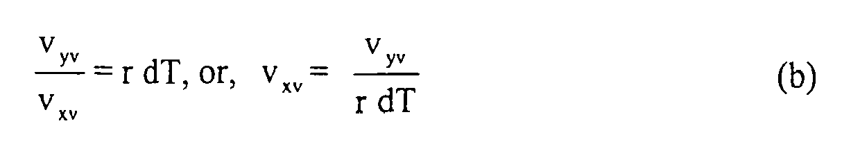
From (a) and (b),
- First, identify the stationary status through a procedure described by the flowchart in Figure 5. Key conditions in the flowchart are defined in the following:
-


Related Counters:
i = 1(On) or 0(Off): Quiet Flag to tell if Quiet Condition is met unless Restart
Condition is on
j: continuous count of successful Quiet Condition during a single stationary event - This is the basic condition for quiet IMU output suggesting potentially stationary vehicle. The threshold values to bound sensor output may depend on IMU performance.
-

- When j reaches 20, it is regarded as that the vehicle is stationary.
-

- Even Quiet Condition is met, the vehicle could still be moving. For example, restarting motion from stationary condition can be very smooth without any peak in acceleration. Restart Condition will identify this case.
-

- When a vehicle stops by breaking, as the magnitude of the forwarding velocity decreases in a step-function manner, there must be a peak in forwarding acceleration max_ax will be used to judge if there was a peak. Normally, Peak Condition followed by Quiet Condition will identify that the vehicle is stationary.
-

- This means that if the vehicle is stationary but Quiet Condition does not follow Peak Condition, Quiet Condition must be continuing.
- This condition is the same as Quiet Condition, except

Related Counters: - m: total count of successful Very Quiet Condition during a single stationary event
- n: continuous count of successful Very Quiet Condition during a single stationary event
- This is a tighter condition for quiet IMU output. Not always, but in some cases this will tell us stationary condition.
- The flow is executed at 10 Hz as an example here. When j reaches 20 or more, it is regarded as that the vehicle is stationary.
- When stationary status is detected by j = 20 or more, the following measurements are used in the
Kalman filter 50 additionally to the GPS measurements:


where
σ P, σQ, and σR are rate gyro measurement accuracy σ (standard deviation) values for P, Q, and R, respectively
Nωi, i = x, y, z; are rate gyro output white noise σ values measured at a certain frequency - Use of the conditions for IMU outputs is up to a designer's choice. Application of Stationary Condition will stop wandering position estimates while the vehicle is stationary.
- Application of the conditions prescribed in the present invention does not need to wait 1 Hz GPS measurement cycle. The
VDC controller 25 sends the measured data indicative of one of the three conditions to the Kalman filter (KF 2) 50 at a frequency higher than GPS measurement such as 10 Hz. Thus, the Kalman filter's update is executed, for example, at 10 Hz based upon the normal condition and the cornering condition, and at 1 Hz based upon the stationary condition and the GPS measurement. This means that the error correction based on the vehicle dynamics conditioning is conducted faster than that of the GPS measurement, thereby minimizing the error accumulation. - Figures 6A and 6B schematically show such effects of the present invention in which patterns of tracking error and correction timings in the integrated INS/GPS navigation system are illustrated. Figure 6A is a pattern involved in the conventional technology, and Figure 6B is a pattern incorporating the vehicle dynamics conditioning of the present invention. As noted above, the GPS measurement is given to the Kalman filter (KF 2) 50 with a repetition rate of 1 Hz. During that period (one second), as shown in Figure 6A, the position tracking errors of the INS are accumulated, and the accumulated errors are corrected by the GPS measurement at every one second since the GPS measurement provides the absolute position and velocity of the vehicle. As shown in Figure 6A, at the last stage of the one second period, the accumulated errors reach a level Ea.
- As noted above, the vehicle dynamics conditioning is conducted at the repletion rate higher than GPS measurement, the time period (less than 1 second), which is several times shorter than that of the GPS measurement. Thus, as shown in Figure 6B, at the last stage of the VDC correction time period, the accumulated errors reach a level Eb which is much smaller than the error level Ea. As a result, even when sufficient GPS signals are unavailable for a long period of time such as 2 minutes, the integrated INS/GPS navigation system of the present invention is able to maintain the relatively high tracking accuracy
- As noted above, in addition to the conventional Kalman filtering process, the measured data based upon the vehicle dynamics condition measured by the inertial sensors are incorporated in the Kalman filtering processing. The measured data are indicative of one of the three predefined vehicle dynamics conditions which help optimizing the position tracking through the Kalman filtering processing. Figures 7-10 show the experimental results to show the effectiveness of the present invention which is demonstrated by conducting on-road data acquisition and formulating a loosely coupled INS/GPS system on a computer to see navigation results in a post-process manner. In Figures 7-10, vehicle trajectories estimated by integrated INS/GPS systems are shown where the vehicle is running through the first floor and underground of a multi-storied parking structure PS.
- Figure 7 shows the results using a conventional loosely coupled INS/GPS system. The vehicle position estimates are shown by thin dots and solid lines, where the solid lines represent the situation of no visible satellites. GPS solutions are also shown by thick dots for comparison. The entire drive from the entrance to exit takes about 7.5 minutes in which total GPS dropouts (solid lines) occasionally last up to 136 seconds. Because of this unfavorable GPS environment, the vehicle position estimates given by the INS/GPS system are far apart from the actual trajectory.
- Meanwhile, Figures 8 and 9 show the results from the loosely coupled INS/GPS system incorporating the present invention where Figure 9 is an enlarged view of Figure 8. Note that the horizontal divergent behaviors are significantly improved where the vehicle motion is reasonably accurately recovered with small yaw angle divergence. The GPS solutions shown by the thick dots provide accurate position tracking only at the areas close to the windows of the parking structure PS where GPS signals are available. Even when the vehicle is in the underground of the parting structure PS, the vehicle motion is traced with sufficient accuracy.
- The three dimensional view of Figure 9 is shown in Figure 10 which demonstrates that vertical divergence is also very small (within ±2m between the heights at the entrance and exit). The path of the center slope connected to the underground level is also accurately recovered. Note that the GPS-only solution fails to show the three dimensional tracking accuracy because its vertical positioning accuracy is much lower than that of the INS/GPS solution.
- As has been described above, according to the present invention, in addition to the conventional integrated INS/GPS navigation system in which outputs of the GPS and the INS are combined by using the Kalman filter, the measured values indicative of predefined vehicle dynamics conditions are also provided to the Kalman filter to obtain optimum estimates of the current position, velocity and orientation of the ground vehicle. As a result, errors involved in tracking the motion of the vehicle is corrected not only by the GPS but the vehicle dynamics conditioning as well. Since the vehicle dynamics conditioning is repeated by a frequency much higher than that of the GPS output, the amount of accumulated error becomes small because the error is corrected within a short period of time. Further, since the accumulated error becomes small, low cost and noisy MEMS sensors can be used in the integrated INS/GPS navigation system.
- In a further aspect, the invention concerns an integrated inertial navigation system/global positioning system navigation system implementing microelectro mechanical system, MEMS, sensors for a ground vehicle, comprising means for defining vehicle dynamics conditions in advance as a function of accelerations and angular rates obtained from inertial sensors; means for receiving the accelerations and angular rates corresponding to coordinates of a ground vehicle from inertial sensors mounted on the inertial navigation system, INS; means for detecting a current dynamics condition of the vehicle by evaluating the accelerations and angular rates from the inertial sensor; means for sending measured data indicative of the detected vehicle dynamics condition to a Kalman filter which integrates the INS and global positioning system, GPS, to conduct a Kalman filter processing incorporating the vehicle dynamics condition; and means for repeating the steps (b) to (d) of
claim 1 to obtain optimum estimates of current vehicle position, velocity and orientation.
Claims (14)
- A navigation method of conditioning ground vehicle's dynamics for a microelectro mechanical system based integrated intertial navigation system/GPS navigation system (20), comprising the steps of:(a) defining vehicle dynamics conditions in advance as a function of accelerations and angular rates obtained from inertial sensors (32);(b) receiving the accelerations and angular rates corresponding to coordinates of a ground vehicle from inertial sensors (32) mounted on the inertial navigation system, INS, (30);(c) detecting a current dynamics condition of the vehicle by evaluating the accelerations and angular rates from the inertial sensor;(d) sending measured data indicative of the detected vehicle dynamics condition to a Kalman filter (50) which integrates the INS and GPS to conduct a Kalman filter processing incorporating the vehicle dynamics condition; and(e) repeating the steps (b) to (d) to obtain optimum estimates of current vehicle position, velocity and orientation.
- The navigation method as defined in Claim 1, wherein one of said vehicle dynamics conditions is a normal condition wherein lateral and downward velocities are assumed to be zero in terms of a vehicle-fixed coordinate system.
- The navigation method as defined in Claim 1 or 2, wherein one of said vehicle dynamics conditions is a cornering condition wherein a forward velocity is estimated from a lateral acceleration and a directional angular rate, and a lateral velocity is assumed to be a small value, and a downward velocity is assumed to be zero, in terms of a vehicle-fixed coordinate system.
- The navigation method as defined in one of Claims 1-3, wherein one of said vehicle dynamics conditions is a stationary condition wherein a vehicle's all three coordinate velocities are assumed to be zero after detecting a stopping status.
- The navigation method as defined in one of Claims 1-4, wherein the inertial sensors are configured by three-axis accelerometers and three-axis gyroscopes in which accelerations corresponding to coordinates of the vehicle are detected by the three accelerometers and the angular rates corresponding to coordinate directions of the vehicle are detected by the three gyroscopes.
- The navigation method as defined in Claim 3, wherein the forward velocity of the vehicle in the cornering condition is estimated by a lateral acceleration and a directional angular rate of the vehicle when the vehicle is cornering.
- The navigation method as defined in Claim 4, wherein the inertial sensors are configured by three accelerometers and three gyroscopes in which the inertial sensors are configured by three accelerometers and three gyroscopes in which outputs of the gyroscopes are assumed to be zero in the stationary condition.
- The navigation method as defined in one of Claims 1-7, wherein said measured data indicative of the detected vehicle dynamics condition is sent to the Kalman filter at a rate higher than that of a GPS output which is indicative of absolute location and velocity of the vehicle.
- The navigation method as defined in Claim 8, wherein said measured data indicative of the detected vehicle dynamics condition is sent to the Kalman filter at a rate of 10Hz and the GPS output indicative of the absolute location and velocity of the vehicle is sent to the Kalman filter at a rate of 1Hz.
- An integrated inertial navigation system/global positioning system navigation system implementing microelectro mechanical system, MEMS, sensors for a ground vehicle, comprising:an inertial navigation system (30), INS, having an inertial measurement unit (32) which incorporates MEMS sensors;a global positioning system, GPS, receiver (40) which receives satellite signals from a plurality of satellites to produce GPS measurements indicating absolute position and velocity of the ground vehicle;a Kalman filter (50) which combines outputs of the INS (30) and the GPS receiver (40) and performs a Kalman filter processing; anda vehicle dynamics conditioning controller (25) which controls an overall operation of the navigation system including vehicle dynamics conditions detected from output of the MEMS sensors;wherein said vehicle dynamics conditions include a normal condition, a cornering condition and a stationary condition of the ground vehicle.
- The integrated INS/GPS navigation system as defined in Claim 10, wherein said MEMS sensors are configured by three-axis accelerometers and three-axis gyroscopes in which accelerations corresponding to coordinates of the vehicle are detected by the three-axis accelerometers and the angular rates corresponding to coordinate directions of the vehicle are detected by the three-axis gyroscopes.
- The integrated INS/GPS navigation system as defined in Claim 10 or 11, wherein one of said vehicle dynamics conditions is a normal condition wherein lateral and downward velocities are assumed to be zero in terms of a vehicle-fixed coordinate system.
- The integrated INS/GPS navigation system as defined in one of Claims 10-12, wherein one of said vehicle dynamics conditions is a cornering condition wherein a forward velocity is estimated from a lateral acceleration and a directional angular rate, and a lateral velocity is assumed to be a small value, and a downward velocity is assumed to be zero, in terms of a vehicle-fixed coordinate system.
- The integrated INS/GPS navigation system as defined in one of Claims 10-13, wherein one of said vehicle dynamics conditions is a stationary condition wherein a vehicle's all three coordinate velocities are assumed to be zero after detecting a stopping status.
Applications Claiming Priority (1)
| Application Number | Priority Date | Filing Date | Title |
|---|---|---|---|
| US11/523,127 US20080071476A1 (en) | 2006-09-19 | 2006-09-19 | Vehicle dynamics conditioning method on MEMS based integrated INS/GPS vehicle navigation system |
Publications (2)
| Publication Number | Publication Date |
|---|---|
| EP1903306A2 true EP1903306A2 (en) | 2008-03-26 |
| EP1903306A3 EP1903306A3 (en) | 2012-11-07 |
Family
ID=38752420
Family Applications (1)
| Application Number | Title | Priority Date | Filing Date |
|---|---|---|---|
| EP07018292A Withdrawn EP1903306A3 (en) | 2006-09-19 | 2007-09-18 | Method and system for estimating ground vehicle dynamics based on an integrated MEMS-INS/GPS navigation system |
Country Status (3)
| Country | Link |
|---|---|
| US (1) | US20080071476A1 (en) |
| EP (1) | EP1903306A3 (en) |
| JP (1) | JP5036462B2 (en) |
Cited By (17)
| Publication number | Priority date | Publication date | Assignee | Title |
|---|---|---|---|---|
| WO2009043183A1 (en) * | 2007-10-04 | 2009-04-09 | University Technologies International | System and method for intelligent tuning of kalman filters for ins/gps navigation applications |
| EP2141507A1 (en) | 2008-07-02 | 2010-01-06 | 02Micro, Inc. | Global positioning system and dead reckoning (GPS&DR) integrated navigation system |
| EP2161582A3 (en) * | 2008-08-29 | 2011-01-26 | Sony Corporation | Velocity calculation device,velocity calculation method, and navigation device |
| EP2290373A1 (en) * | 2009-08-28 | 2011-03-02 | Sony Corporation | Velocity calculation device, velocity calculation method and associated navigation device |
| EP2295989A1 (en) * | 2009-09-14 | 2011-03-16 | Sony Corporation | Velocity calculating device, velocity calculating method, and navigation device |
| CN101614560B (en) * | 2009-07-15 | 2011-03-16 | 无锡爱睿芯电子有限公司 | Movement recorder based on GPS positioning and method thereof |
| EP2330427A1 (en) * | 2009-12-03 | 2011-06-08 | Sony Corporation | Velocity calculating apparatus, velocity calculating method, navigation apparatus, and mobile phone with navigation function |
| CN101476894B (en) * | 2009-02-01 | 2011-06-29 | 哈尔滨工业大学 | Vehicle-mounted SINS/GPS combined navigation system performance reinforcement method |
| GB2477407A (en) * | 2010-01-28 | 2011-08-03 | Sirf Technology Holdings Inc | GNSS performance enhancement using accelerometer only data |
| WO2011156790A1 (en) * | 2010-06-10 | 2011-12-15 | Qualcomm Incorporated | Use of inertial sensor data to improve mobile station positioning |
| WO2014149042A1 (en) * | 2013-03-20 | 2014-09-25 | International Truck Intellectual Property Company, Llc | Smart cruise control system |
| CN104864867A (en) * | 2015-05-18 | 2015-08-26 | 南京邮电大学 | Method for correcting positioning error of vehicle in VSYR (vehicle speed and yaw rate) blind area by using GNSS (global navigation satellite system) |
| CN105606094A (en) * | 2016-02-19 | 2016-05-25 | 北京航天控制仪器研究所 | Information condition matched-filtering estimation method based on MEMS/GPS combined system |
| CN105741558A (en) * | 2016-02-05 | 2016-07-06 | 广西科技大学 | Detection method of carrying out dual tracking on front vehicle under night vision environment |
| DE102015218810A1 (en) | 2015-09-29 | 2017-03-30 | Continental Teves Ag & Co. Ohg | Method for selecting location algorithms in a vehicle |
| CN110288154A (en) * | 2019-06-25 | 2019-09-27 | 北京百度网讯科技有限公司 | Speed predicting method, device, equipment and medium |
| CN110440795A (en) * | 2019-07-30 | 2019-11-12 | 北京航空航天大学 | A kind of Angular Acceleration Estimation based on Kalman filtering |
Families Citing this family (38)
| Publication number | Priority date | Publication date | Assignee | Title |
|---|---|---|---|---|
| JP4781300B2 (en) * | 2007-03-01 | 2011-09-28 | アルパイン株式会社 | Position detection apparatus and position detection method |
| JP4964047B2 (en) * | 2007-07-12 | 2012-06-27 | アルパイン株式会社 | Position detection apparatus and position detection method |
| US8024119B2 (en) * | 2007-08-14 | 2011-09-20 | Honeywell International Inc. | Systems and methods for gyrocompass alignment using dynamically calibrated sensor data and an iterated extended kalman filter within a navigation system |
| JP5164645B2 (en) * | 2008-04-07 | 2013-03-21 | アルパイン株式会社 | Method and apparatus for repetitive calculation control in Kalman filter processing |
| JP5328252B2 (en) * | 2008-07-30 | 2013-10-30 | アルパイン株式会社 | Position detection apparatus and position detection method for navigation system |
| EP2380134A1 (en) | 2008-12-19 | 2011-10-26 | Xollai, Llc | System and method for determining an orientation and position of an object |
| US20100256939A1 (en) * | 2009-04-03 | 2010-10-07 | The Regents Of The University Of Michigan | Heading Error Removal System for Tracking Devices |
| US20110087450A1 (en) * | 2009-04-03 | 2011-04-14 | University Of Michigan | Heading Error Removal System for Tracking Devices |
| US8249800B2 (en) | 2009-06-09 | 2012-08-21 | Alpine Electronics, Inc. | Method and apparatus to detect platform stationary status using three-axis accelerometer outputs |
| JP5482047B2 (en) * | 2009-09-15 | 2014-04-23 | ソニー株式会社 | Speed calculation device, speed calculation method, and navigation device |
| JP2011064501A (en) * | 2009-09-15 | 2011-03-31 | Sony Corp | Navigation apparatus, navigation method, and cellular phone with navigation function |
| JP5419665B2 (en) * | 2009-12-10 | 2014-02-19 | 三菱電機株式会社 | POSITION LOCATION DEVICE, POSITION LOCATION METHOD, POSITION LOCATION PROGRAM, Velocity Vector Calculation Device, Velocity Vector Calculation Method, and Velocity Vector Calculation Program |
| US20110313650A1 (en) * | 2010-06-21 | 2011-12-22 | Qualcomm Incorporated | Inertial sensor orientation detection and measurement correction for navigation device |
| US9534900B2 (en) | 2011-02-17 | 2017-01-03 | Systron Donner Interial, Inc. | Inertial navigation sculling algorithm |
| JP5602070B2 (en) * | 2011-03-15 | 2014-10-08 | 三菱電機株式会社 | POSITIONING DEVICE, POSITIONING METHOD OF POSITIONING DEVICE, AND POSITIONING PROGRAM |
| KR101331956B1 (en) | 2011-03-21 | 2013-11-21 | 엘아이지넥스원 주식회사 | High precision ins module using analog mems sensor and operating method thereof |
| JP5724676B2 (en) * | 2011-06-27 | 2015-05-27 | 富士通株式会社 | Portable terminal device, speed calculation method, and speed calculation program |
| CN102508278B (en) * | 2011-11-28 | 2013-09-18 | 北京航空航天大学 | Adaptive filtering method based on observation noise covariance matrix estimation |
| DE102012224103A1 (en) * | 2012-12-20 | 2014-06-26 | Continental Teves Ag & Co. Ohg | Device for outputting a measurement signal indicating a physical measurand |
| JP6383907B2 (en) * | 2014-07-07 | 2018-09-05 | 多摩川精機株式会社 | Vehicle position measuring apparatus and method |
| WO2016077057A2 (en) * | 2014-10-24 | 2016-05-19 | Bounce Imaging, Inc. | Imaging systems and methods |
| US9568592B1 (en) | 2014-11-04 | 2017-02-14 | Google Inc. | Automotive sensor alignment with external IMU tool |
| JP6422912B2 (en) * | 2016-04-06 | 2018-11-14 | 株式会社クボタ | POSITIONING DETECTION DEVICE AND WORKING MACHINE HAVING POSITIONING DETECTION DEVICE |
| CN106595655A (en) * | 2016-12-14 | 2017-04-26 | 中国电子科技集团公司第二十研究所 | Double-satellite integrated positioning method based on inertial sensor |
| CN106767847B (en) * | 2016-12-15 | 2020-11-20 | 北京三驰科技发展有限公司 | Vehicle attitude safety early warning method and system |
| US11441907B2 (en) | 2017-01-30 | 2022-09-13 | Mitsubishi Electric Corporation | Positioning device and positioning method |
| US10705105B2 (en) * | 2017-07-21 | 2020-07-07 | Applied Concepts, Inc. | Absolute speed detector |
| JP6988859B2 (en) * | 2019-06-07 | 2022-01-05 | トヨタ自動車株式会社 | Self-location sharing system, vehicle and terminal |
| CN112771411A (en) * | 2020-04-24 | 2021-05-07 | 深圳市大疆创新科技有限公司 | Positioning method, system and storage medium |
| CN113932820A (en) * | 2020-06-29 | 2022-01-14 | 杭州海康威视数字技术股份有限公司 | Object detection method and device |
| CN111912426A (en) * | 2020-08-10 | 2020-11-10 | 电子科技大学 | Low-cost odometer design method based on MEMS IMU |
| CN111829517A (en) * | 2020-08-19 | 2020-10-27 | 三一机器人科技有限公司 | AGV navigation positioning system and method |
| CN112731483B (en) * | 2020-12-14 | 2024-04-09 | 北京航空航天大学 | Method for judging RTK abnormal value in automatic driving integrated navigation system |
| JP7177862B2 (en) * | 2021-01-04 | 2022-11-24 | 本田技研工業株式会社 | positioning device |
| CN112577527B (en) * | 2021-02-25 | 2021-09-17 | 北京主线科技有限公司 | Vehicle-mounted IMU error calibration method and device |
| US11626661B2 (en) * | 2021-06-16 | 2023-04-11 | L3Harris Technologies, Inc. | Vehicle having antenna positioner adjusted for timing latency and associated methods |
| GB2618843A (en) * | 2022-05-20 | 2023-11-22 | Appy Risk Tech Limited | A method and system for generating a vehicle mileage |
| US20230400306A1 (en) * | 2022-06-14 | 2023-12-14 | Volvo Car Corporation | Localization for autonomous movement using vehicle sensors |
Citations (3)
| Publication number | Priority date | Publication date | Assignee | Title |
|---|---|---|---|---|
| US6205401B1 (en) * | 1995-09-19 | 2001-03-20 | Litef Gmbh | Navigation system for a vehicle, especially a land craft |
| EP1221586A2 (en) * | 2001-01-08 | 2002-07-10 | Motorola, Inc. | Position and heading error-correction method and apparatus for vehicle navigation systems |
| US6859727B2 (en) * | 2003-01-08 | 2005-02-22 | Honeywell International, Inc. | Attitude change kalman filter measurement apparatus and method |
Family Cites Families (14)
| Publication number | Priority date | Publication date | Assignee | Title |
|---|---|---|---|---|
| JP3075889B2 (en) * | 1993-05-31 | 2000-08-14 | 株式会社日立製作所 | Navigation device |
| US5862511A (en) * | 1995-12-28 | 1999-01-19 | Magellan Dis, Inc. | Vehicle navigation system and method |
| JPH10293038A (en) * | 1997-04-21 | 1998-11-04 | Honda Motor Co Ltd | Path-guiding device for pedestrian |
| JP3780617B2 (en) * | 1997-04-28 | 2006-05-31 | 日産自動車株式会社 | Automatic vehicle steering system |
| JP3375268B2 (en) * | 1997-05-27 | 2003-02-10 | 株式会社日立製作所 | Navigation device |
| US6282496B1 (en) * | 1999-10-29 | 2001-08-28 | Visteon Technologies, Llc | Method and apparatus for inertial guidance for an automobile navigation system |
| JP4311854B2 (en) * | 2000-03-28 | 2009-08-12 | クラリオン株式会社 | GPS receiver with feedback of map matching results |
| US6445983B1 (en) * | 2000-07-07 | 2002-09-03 | Case Corporation | Sensor-fusion navigator for automated guidance of off-road vehicles |
| JP2002318274A (en) * | 2001-02-13 | 2002-10-31 | Mazda Motor Corp | Instrument and method for measuring car body movement and recording medium where the method is recorded |
| JP2004151910A (en) * | 2002-10-30 | 2004-05-27 | Hitachi Ltd | Vehicle travel support system and method |
| JP4199553B2 (en) * | 2003-02-03 | 2008-12-17 | 古野電気株式会社 | Hybrid navigation device |
| JP2005195395A (en) * | 2004-01-05 | 2005-07-21 | Mitsubishi Electric Corp | Moving object acceleration/distance estimating circuit, pseudo-distance estimating circuit for positioning navigation, moving object positioning device, and moving object positioning method |
| JP2005274186A (en) * | 2004-03-23 | 2005-10-06 | Xanavi Informatics Corp | Acceleration calculation method of navigation device |
| US7274504B2 (en) * | 2005-01-14 | 2007-09-25 | L-3 Communications Corporation | System and method for advanced tight coupling of GPS and inertial navigation sensors |
-
2006
- 2006-09-19 US US11/523,127 patent/US20080071476A1/en not_active Abandoned
-
2007
- 2007-09-10 JP JP2007233515A patent/JP5036462B2/en not_active Expired - Fee Related
- 2007-09-18 EP EP07018292A patent/EP1903306A3/en not_active Withdrawn
Patent Citations (3)
| Publication number | Priority date | Publication date | Assignee | Title |
|---|---|---|---|---|
| US6205401B1 (en) * | 1995-09-19 | 2001-03-20 | Litef Gmbh | Navigation system for a vehicle, especially a land craft |
| EP1221586A2 (en) * | 2001-01-08 | 2002-07-10 | Motorola, Inc. | Position and heading error-correction method and apparatus for vehicle navigation systems |
| US6859727B2 (en) * | 2003-01-08 | 2005-02-22 | Honeywell International, Inc. | Attitude change kalman filter measurement apparatus and method |
Cited By (37)
| Publication number | Priority date | Publication date | Assignee | Title |
|---|---|---|---|---|
| WO2009043183A1 (en) * | 2007-10-04 | 2009-04-09 | University Technologies International | System and method for intelligent tuning of kalman filters for ins/gps navigation applications |
| EP2141507A1 (en) | 2008-07-02 | 2010-01-06 | 02Micro, Inc. | Global positioning system and dead reckoning (GPS&DR) integrated navigation system |
| JP2010014715A (en) * | 2008-07-02 | 2010-01-21 | O2 Micro Inc | Global positioning system and dead reckoning (gps&dr) integrated navigation system |
| CN101762805B (en) * | 2008-07-02 | 2012-09-05 | 凹凸电子(武汉)有限公司 | Integrated navigation system and navigation method |
| US8239133B2 (en) | 2008-07-02 | 2012-08-07 | O2Micro, International | Global positioning system and dead reckoning (GPSandDR) integrated navigation system |
| US8989982B2 (en) | 2008-08-29 | 2015-03-24 | Sony Corporation | Velocity calculation device, velocity calculation method, and navigation device |
| EP2161582A3 (en) * | 2008-08-29 | 2011-01-26 | Sony Corporation | Velocity calculation device,velocity calculation method, and navigation device |
| US9658067B2 (en) | 2008-08-29 | 2017-05-23 | Sony Corporation | Velocity calculation device, velocity calculation method, and navigation device |
| US9513124B2 (en) | 2008-08-29 | 2016-12-06 | Sony Corporation | Velocity calculation device, velocity calculation method, and navigation device |
| CN101476894B (en) * | 2009-02-01 | 2011-06-29 | 哈尔滨工业大学 | Vehicle-mounted SINS/GPS combined navigation system performance reinforcement method |
| CN101614560B (en) * | 2009-07-15 | 2011-03-16 | 无锡爱睿芯电子有限公司 | Movement recorder based on GPS positioning and method thereof |
| EP2290373A1 (en) * | 2009-08-28 | 2011-03-02 | Sony Corporation | Velocity calculation device, velocity calculation method and associated navigation device |
| CN102023232B (en) * | 2009-09-14 | 2013-09-11 | 索尼公司 | Velocity calculating device, velocity calculating method, and navigation device |
| CN102023232A (en) * | 2009-09-14 | 2011-04-20 | 索尼公司 | Velocity calculating device, velocity calculating method, and navigation device |
| EP2295989A1 (en) * | 2009-09-14 | 2011-03-16 | Sony Corporation | Velocity calculating device, velocity calculating method, and navigation device |
| US8473208B2 (en) | 2009-09-14 | 2013-06-25 | Sony Corporation | Velocity calculating device, velocity calculating method, and navigation device |
| US8457923B2 (en) | 2009-12-03 | 2013-06-04 | Sony Corporation | Velocity calculating apparatus, velocity calculating method, navigation apparatus, and mobile phone with navigation function |
| CN102087299A (en) * | 2009-12-03 | 2011-06-08 | 索尼公司 | Velocity calculating apparatus, velocity calculating method, navigation apparatus, and mobile phone with navigation function |
| CN102087299B (en) * | 2009-12-03 | 2012-11-21 | 索尼公司 | Velocity calculating apparatus, velocity calculating method, navigation apparatus, and mobile phone with navigation function |
| EP2330427A1 (en) * | 2009-12-03 | 2011-06-08 | Sony Corporation | Velocity calculating apparatus, velocity calculating method, navigation apparatus, and mobile phone with navigation function |
| US8311740B2 (en) | 2010-01-28 | 2012-11-13 | CSR Technology Holdings Inc. | Use of accelerometer only data to improve GNSS performance |
| GB2477407B (en) * | 2010-01-28 | 2013-12-04 | Sirf Technology Holdings Inc | GNSS performance enchancement using accelerometer-only data |
| US8935093B2 (en) | 2010-01-28 | 2015-01-13 | CSR Technology Holdings Inc. | GNSS performance enhancement using accelerometer-only data |
| GB2477407A (en) * | 2010-01-28 | 2011-08-03 | Sirf Technology Holdings Inc | GNSS performance enhancement using accelerometer only data |
| WO2011156790A1 (en) * | 2010-06-10 | 2011-12-15 | Qualcomm Incorporated | Use of inertial sensor data to improve mobile station positioning |
| US9052202B2 (en) | 2010-06-10 | 2015-06-09 | Qualcomm Incorporated | Use of inertial sensor data to improve mobile station positioning |
| CN102933937A (en) * | 2010-06-10 | 2013-02-13 | 高通股份有限公司 | Use of inertial sensor data to improve mobile station positioning |
| WO2014149042A1 (en) * | 2013-03-20 | 2014-09-25 | International Truck Intellectual Property Company, Llc | Smart cruise control system |
| CN104864867B (en) * | 2015-05-18 | 2017-07-14 | 南京邮电大学 | GNSS vehicle is applicable in VSYR blind areas position error modification method |
| CN104864867A (en) * | 2015-05-18 | 2015-08-26 | 南京邮电大学 | Method for correcting positioning error of vehicle in VSYR (vehicle speed and yaw rate) blind area by using GNSS (global navigation satellite system) |
| DE102015218810A1 (en) | 2015-09-29 | 2017-03-30 | Continental Teves Ag & Co. Ohg | Method for selecting location algorithms in a vehicle |
| US10809387B2 (en) | 2015-09-29 | 2020-10-20 | Continental Automotive Systems, Inc. | Method for selecting localization algorithms in a vehicle |
| CN105741558A (en) * | 2016-02-05 | 2016-07-06 | 广西科技大学 | Detection method of carrying out dual tracking on front vehicle under night vision environment |
| CN105606094A (en) * | 2016-02-19 | 2016-05-25 | 北京航天控制仪器研究所 | Information condition matched-filtering estimation method based on MEMS/GPS combined system |
| CN105606094B (en) * | 2016-02-19 | 2018-08-21 | 北京航天控制仪器研究所 | A kind of information condition matched filtering method of estimation based on MEMS/GPS combined systems |
| CN110288154A (en) * | 2019-06-25 | 2019-09-27 | 北京百度网讯科技有限公司 | Speed predicting method, device, equipment and medium |
| CN110440795A (en) * | 2019-07-30 | 2019-11-12 | 北京航空航天大学 | A kind of Angular Acceleration Estimation based on Kalman filtering |
Also Published As
| Publication number | Publication date |
|---|---|
| JP5036462B2 (en) | 2012-09-26 |
| US20080071476A1 (en) | 2008-03-20 |
| EP1903306A3 (en) | 2012-11-07 |
| JP2008076389A (en) | 2008-04-03 |
Similar Documents
| Publication | Publication Date | Title |
|---|---|---|
| EP1903306A2 (en) | Method and system for estimating ground vehicle dynamics based on an integrated MEMS-INS/GPS navigation system | |
| US8249800B2 (en) | Method and apparatus to detect platform stationary status using three-axis accelerometer outputs | |
| CN106289275B (en) | Unit and method for improving positioning accuracy | |
| US8510044B2 (en) | Position sensing device and method | |
| EP2045577B1 (en) | Positioning device, and navigation system | |
| US6826478B2 (en) | Inertial navigation system for mobile objects with constraints | |
| KR101761933B1 (en) | Movement condition detection device | |
| US7096116B2 (en) | Vehicle behavior detector, in-vehicle processing system, detection information calibrator, and in-vehicle processor | |
| EP1722239B1 (en) | Apparatus and method for measuring speed of a moving object | |
| EP1653194B1 (en) | Azimuth/attitude detecting sensor | |
| US8666589B2 (en) | Device and method for determining the driving state of a vehicle | |
| EP1315945B1 (en) | Calibration of multi-axis accelerometer in vehicle navigation system using gps data | |
| EP2244099B1 (en) | Integrated satellite navigation and dead-reckoning navigation positioning device | |
| EP4303630A2 (en) | Gnss and inertial navigation system utilizing relative yaw as an observable for an ins filter | |
| EP3385671A1 (en) | A navigation system utilizing yaw rate constraint during inertial dead reckoning | |
| WO2014002211A1 (en) | Positioning device | |
| EP2249172B1 (en) | Satellite navigation/dead-reckoning navigation integrated positioning device | |
| US11079494B2 (en) | Positioning device | |
| WO2009061870A1 (en) | Systems and methods for global differential positioning | |
| KR20140067119A (en) | Orientation model for a sensor system | |
| JP2008215917A (en) | Position detector and position detection method | |
| EP2219044A1 (en) | Navigation method, navigation system, navigation device, vehicle provided therewith and group of vehicles | |
| JP2018047888A (en) | System and method for measuring angular position of vehicle | |
| JP2011185899A (en) | Position locating device, position locating method of position locating device and position locating program | |
| KR100525517B1 (en) | Car navigation system and control method thereof |
Legal Events
| Date | Code | Title | Description |
|---|---|---|---|
| PUAI | Public reference made under article 153(3) epc to a published international application that has entered the european phase |
Free format text: ORIGINAL CODE: 0009012 |
|
| AK | Designated contracting states |
Kind code of ref document: A2 Designated state(s): AT BE BG CH CY CZ DE DK EE ES FI FR GB GR HU IE IS IT LI LT LU LV MC MT NL PL PT RO SE SI SK TR |
|
| AX | Request for extension of the european patent |
Extension state: AL BA HR MK YU |
|
| PUAL | Search report despatched |
Free format text: ORIGINAL CODE: 0009013 |
|
| AK | Designated contracting states |
Kind code of ref document: A3 Designated state(s): AT BE BG CH CY CZ DE DK EE ES FI FR GB GR HU IE IS IT LI LT LU LV MC MT NL PL PT RO SE SI SK TR |
|
| AX | Request for extension of the european patent |
Extension state: AL BA HR MK RS |
|
| RIC1 | Information provided on ipc code assigned before grant |
Ipc: G01C 21/16 20060101AFI20120928BHEP Ipc: G01S 5/14 20060101ALI20120928BHEP |
|
| AKY | No designation fees paid | ||
| REG | Reference to a national code |
Ref country code: DE Ref legal event code: R108 |
|
| REG | Reference to a national code |
Ref country code: DE Ref legal event code: R108 Effective date: 20130710 |
|
| STAA | Information on the status of an ep patent application or granted ep patent |
Free format text: STATUS: THE APPLICATION IS DEEMED TO BE WITHDRAWN |
|
| 18D | Application deemed to be withdrawn |
Effective date: 20130508 |