EP1903209A1 - Device to attach a fuel return line to a fuel injector and device to suction fuel from a fuel injector - Google Patents
Device to attach a fuel return line to a fuel injector and device to suction fuel from a fuel injector Download PDFInfo
- Publication number
- EP1903209A1 EP1903209A1 EP07024179A EP07024179A EP1903209A1 EP 1903209 A1 EP1903209 A1 EP 1903209A1 EP 07024179 A EP07024179 A EP 07024179A EP 07024179 A EP07024179 A EP 07024179A EP 1903209 A1 EP1903209 A1 EP 1903209A1
- Authority
- EP
- European Patent Office
- Prior art keywords
- housing part
- accordance
- connection
- fuel
- retaining
- Prior art date
- Legal status (The legal status is an assumption and is not a legal conclusion. Google has not performed a legal analysis and makes no representation as to the accuracy of the status listed.)
- Granted
Links
- 239000000446 fuel Substances 0.000 title claims abstract description 46
- 230000002093 peripheral effect Effects 0.000 claims description 2
- 239000012530 fluid Substances 0.000 description 4
- 238000003466 welding Methods 0.000 description 4
- 238000003780 insertion Methods 0.000 description 2
- 230000037431 insertion Effects 0.000 description 2
- 238000009434 installation Methods 0.000 description 2
- 238000004519 manufacturing process Methods 0.000 description 2
- 230000001419 dependent effect Effects 0.000 description 1
- 238000009826 distribution Methods 0.000 description 1
- 238000005516 engineering process Methods 0.000 description 1
- 238000002347 injection Methods 0.000 description 1
- 239000007924 injection Substances 0.000 description 1
- 238000001746 injection moulding Methods 0.000 description 1
- 238000000034 method Methods 0.000 description 1
Images


Classifications
-
- F—MECHANICAL ENGINEERING; LIGHTING; HEATING; WEAPONS; BLASTING
- F02—COMBUSTION ENGINES; HOT-GAS OR COMBUSTION-PRODUCT ENGINE PLANTS
- F02M—SUPPLYING COMBUSTION ENGINES IN GENERAL WITH COMBUSTIBLE MIXTURES OR CONSTITUENTS THEREOF
- F02M55/00—Fuel-injection apparatus characterised by their fuel conduits or their venting means; Arrangements of conduits between fuel tank and pump F02M37/00
- F02M55/002—Arrangement of leakage or drain conduits in or from injectors
-
- F—MECHANICAL ENGINEERING; LIGHTING; HEATING; WEAPONS; BLASTING
- F02—COMBUSTION ENGINES; HOT-GAS OR COMBUSTION-PRODUCT ENGINE PLANTS
- F02M—SUPPLYING COMBUSTION ENGINES IN GENERAL WITH COMBUSTIBLE MIXTURES OR CONSTITUENTS THEREOF
- F02M55/00—Fuel-injection apparatus characterised by their fuel conduits or their venting means; Arrangements of conduits between fuel tank and pump F02M37/00
- F02M55/004—Joints; Sealings
-
- F—MECHANICAL ENGINEERING; LIGHTING; HEATING; WEAPONS; BLASTING
- F04—POSITIVE - DISPLACEMENT MACHINES FOR LIQUIDS; PUMPS FOR LIQUIDS OR ELASTIC FLUIDS
- F04F—PUMPING OF FLUID BY DIRECT CONTACT OF ANOTHER FLUID OR BY USING INERTIA OF FLUID TO BE PUMPED; SIPHONS
- F04F5/00—Jet pumps, i.e. devices in which flow is induced by pressure drop caused by velocity of another fluid flow
- F04F5/02—Jet pumps, i.e. devices in which flow is induced by pressure drop caused by velocity of another fluid flow the inducing fluid being liquid
- F04F5/10—Jet pumps, i.e. devices in which flow is induced by pressure drop caused by velocity of another fluid flow the inducing fluid being liquid displacing liquids, e.g. containing solids, or liquids and elastic fluids
-
- F—MECHANICAL ENGINEERING; LIGHTING; HEATING; WEAPONS; BLASTING
- F04—POSITIVE - DISPLACEMENT MACHINES FOR LIQUIDS; PUMPS FOR LIQUIDS OR ELASTIC FLUIDS
- F04F—PUMPING OF FLUID BY DIRECT CONTACT OF ANOTHER FLUID OR BY USING INERTIA OF FLUID TO BE PUMPED; SIPHONS
- F04F5/00—Jet pumps, i.e. devices in which flow is induced by pressure drop caused by velocity of another fluid flow
- F04F5/44—Component parts, details, or accessories not provided for in, or of interest apart from, groups F04F5/02 - F04F5/42
-
- F—MECHANICAL ENGINEERING; LIGHTING; HEATING; WEAPONS; BLASTING
- F04—POSITIVE - DISPLACEMENT MACHINES FOR LIQUIDS; PUMPS FOR LIQUIDS OR ELASTIC FLUIDS
- F04F—PUMPING OF FLUID BY DIRECT CONTACT OF ANOTHER FLUID OR BY USING INERTIA OF FLUID TO BE PUMPED; SIPHONS
- F04F5/00—Jet pumps, i.e. devices in which flow is induced by pressure drop caused by velocity of another fluid flow
- F04F5/44—Component parts, details, or accessories not provided for in, or of interest apart from, groups F04F5/02 - F04F5/42
- F04F5/46—Arrangements of nozzles
-
- F—MECHANICAL ENGINEERING; LIGHTING; HEATING; WEAPONS; BLASTING
- F16—ENGINEERING ELEMENTS AND UNITS; GENERAL MEASURES FOR PRODUCING AND MAINTAINING EFFECTIVE FUNCTIONING OF MACHINES OR INSTALLATIONS; THERMAL INSULATION IN GENERAL
- F16L—PIPES; JOINTS OR FITTINGS FOR PIPES; SUPPORTS FOR PIPES, CABLES OR PROTECTIVE TUBING; MEANS FOR THERMAL INSULATION IN GENERAL
- F16L37/00—Couplings of the quick-acting type
- F16L37/008—Couplings of the quick-acting type for branching pipes; for joining pipes to walls
-
- F—MECHANICAL ENGINEERING; LIGHTING; HEATING; WEAPONS; BLASTING
- F16—ENGINEERING ELEMENTS AND UNITS; GENERAL MEASURES FOR PRODUCING AND MAINTAINING EFFECTIVE FUNCTIONING OF MACHINES OR INSTALLATIONS; THERMAL INSULATION IN GENERAL
- F16L—PIPES; JOINTS OR FITTINGS FOR PIPES; SUPPORTS FOR PIPES, CABLES OR PROTECTIVE TUBING; MEANS FOR THERMAL INSULATION IN GENERAL
- F16L47/00—Connecting arrangements or other fittings specially adapted to be made of plastics or to be used with pipes made of plastics
- F16L47/26—Connecting arrangements or other fittings specially adapted to be made of plastics or to be used with pipes made of plastics for branching pipes; for joining pipes to walls; Adaptors therefor
- F16L47/32—Branch units, e.g. made in one piece, welded, riveted
-
- F—MECHANICAL ENGINEERING; LIGHTING; HEATING; WEAPONS; BLASTING
- F02—COMBUSTION ENGINES; HOT-GAS OR COMBUSTION-PRODUCT ENGINE PLANTS
- F02M—SUPPLYING COMBUSTION ENGINES IN GENERAL WITH COMBUSTIBLE MIXTURES OR CONSTITUENTS THEREOF
- F02M2200/00—Details of fuel-injection apparatus, not otherwise provided for
- F02M2200/80—Fuel injection apparatus manufacture, repair or assembly
- F02M2200/803—Fuel injection apparatus manufacture, repair or assembly using clamp elements and fastening means; e.g. bolts or screws
Definitions
- fuel injectors are provided with fuel return lines through which the fuel which is not consumed at the fuel injector is returned to the tank.
- the fuel injector provides a drain passage for this purpose to which a connector for a retaining clamp can be attached.
- the retaining clamp for its part possesses a connecting fitting for the fuel return line. In this way, the excess fuel can be drawn off to the tank.
- the retaining clamp is designed as a self-locking clip and has two retaining arms which partially encircle the fuel injector. Since the retaining clamp must not become detached from the fuel injector or loosen its seat during operation, it is seated relatively tightly on the fuel injector, which has the disadvantage that relatively high installation force is necessary to push the retaining clip onto the fuel injector.
- devices for generating negative pressure by utilizing the venturi principle are sufficiently known.
- a flowing medium is accelerated by means of a restriction in the cross section, which reduces the pressure of the medium.
- the suction line opens into this area of reduced pressure so that a fluid can be sucked in through this_suction line.
- the object of the invention is to provide a device of the type mentioned at the beginning, with which firstly the installation force to push the device onto a fuel injector is reduced, secondly the retaining force, or the pull-off force, is increased, or at least not reduced. It would be advantageous if the device consists of few parts and is simple to assemble and install.
- the injector is a formed part of the first part of the housing. This means that the entire device in accordance with the invention consists of two components: the first housing part with the injector and first connection and the second housing part with the third connection. This reduces not only production costs but also assembly and warehousing costs.
- the first housing part is configured essentially cartridge-shaped, with the injector located coaxially in the first housing part.
- the cartridge-shaped structure has the advantage that it is easily possible to manufacture the first housing part using injection molding technology, and there is no problem in forming the injector on the first housing part.
- the second connection is preferably formed either at the first or at the second housing part. If the second connection is located on the second housing part, the latter can also easily be manufactured as an injection molded part, particularly from two housing shell halves which are joined by friction welding or ultrasonic welding.
- the second housing part preferably has a cartridge-shaped axial extension which encircles the injector nozzle and locates same.
- the injector nozzle is carried in the axial extension which defines the precise position of the outlet for the injector nozzle in the second housing part. This is achieved by the extension centering the injector nozzle in the radial direction, that is to say, aligning it coaxially and additionally defining the depth of insertion.
- retaining arms extending in the axial direction are provided on the first housing part which partially overlap the second housing part and.
- these retaining arms are provided on the second housing part and extend over the first housing part in the axial direction.
- the retaining arms are configured as locking arms. The two housing parts are connected to each other by means of these retaining arms, specifically they are latched together. For this reason, no tool is required for assembly and assembly can be carried out specifically by machine.
- Optimal distribution of force and symmetrical design of the housing parts is achieved by providing two oppositely located retaining arms. These two retaining arms also ensure that the two housing parts are connected in a fluid-tight manner, so that no fuel escapes at the joint and no air is sucked in.
- the retaining means have locking tabs or locking slots and the retaining arms have locking slots or locking tabs.
- Such simply designed retaining means are inexpensive to produce, are easy to engage and are reliable, even over a long period, with respect to their engagement, the retaining force and any possible play.
- the second housing part is provided with longitudinal guides for the retaining arms.
- these longitudinal guides allow the retaining arms to be positioned easily against the other housing part and pushed onto same.
- the retaining arms specifically possess bevels at their free ends and may be configured in such a way that the two housing parts can be joined only when aligned to each other in one way, thereby precluding incorrect assembly.
- the longitudinal guides preferably abut the retaining arms laterally.
- At least two longitudinal guides position a retaining arm between themselves. These longitudinal guides form, so to speak, a channel into which the retaining arm can be introduced.
- the longitudinal guides additionally support the retaining arm in the peripheral direction, which has the substantial advantage that torsional forces impinging on one housing part are not transferred to the other housing part by the latched connection but by the longitudinal guide. This is important, for example, after the housing parts have been joined, that is to say, with a completely assembled device, when the high-pressure line and/or the return line is pushed on or pulled off, since torsional forces affect the housing parts during this procedure.
- the longitudinal guide serves to provide lateral support and protection for the latched connection.
- the longitudinal guide is formed by a radial projection or recess running in the longitudinal direction.
- the longitudinal guide is a projection, it can form part of a channel, whereas if the longitudinal projection is configured as a recess, it forms a guide groove which is formed into the housing wall in the longitudinal direction.
- the suction device 218 has a first connection 222 to which a high-pressure line 224 can be connected. Fuel under pressure is transported in this high-pressure line 224 towards the suction device 218. In a center area of the suction device 218, there is a second connection 226 to which the return line 216 is connected. A third connection 228 is provided opposite the first connection 222 to which a drain line 230 can be connected. The fuel brought in through the high-pressure line 224 and the return line 216 of the suction device 218 is taken away through this drain line 230, for example, to the tank.
- the suction device 28 consists of a housing part 232, shown in Figure 3 , onto which the first connection 222 is formed and a second housing part 234, which is shown in Figure 4 .
- the second connection 226 and the third connection 228 project radially or axially from this second housing part 234.
- areas 236 can be seen in which housing ribs 238 are provided running in the longitudinal direction, that is to say axially, to which the retaining clip 220 fastens.
- a fuel injector 240 which is aligned coaxially to the longitudinal axis 242 of the first housing part 232 is provided opposite the first connection 222.
- the fuel injector 240 is flanked by two retaining arms 244 located opposite each other whose free ends have leading bevels 248.
- the retaining arms 244 are given locking slots 250 which coact, specifically engage, with locking tabs 252 on the second housing part 234.
- the slots 250 and the tabs 252 form retaining means 246 for the retaining arms 244.
- the first housing part 232 has an essentially cartridge-shaped configuration, in which the injector nozzle 240 extends coaxially and is connected to the first connection 222.
- the injector nozzle possesses a narrow injector opening 254 in which the fluid being carried, specifically the fuel being carried, is accelerated to maximum speed.
- the opening 56 of the second connection 226 In the immediate vicinity of this injector opening is the opening 56 of the second connection 226 through which the fuel is suctioned off from the return line 216 through the negative pressure generated.
- the exact alignment of the opening 256 relative to the nozzle opening 254 is achieved by a stop 258 on the first housing part 232 for an insertion sleeve 260 which is formed coaxially onto the second housing part 234 and surrounds the injector nozzle.
- the diffuser required for the venturi system can be seen in the second housing part 234.
- two longitudinal guides 264 which abut the retaining arms 244 laterally when they are latched to the locking tabs 252, can be seen in the views of the second housing part shown in Figures 6 and 7 . These longitudinal guides 264 prevent the two housing parts 232 and 234 from being rotated relative to each other in their latched position.
- the outlet or opening 256 of the second connection 226, that is the opening 256 in the flow duct 266 of the venturi system, is shown in Figure 7 .
- This opening 256 lies in a defined position relative to the nozzle opening 254 when the housing parts 232 and 234 are latched.
- the design of the device 218 with two housing parts 232 and 234 in accordance with the invention has the considerable advantage that it can manufactured and assembled easily and warehousing costs are reduced.
Landscapes
- Engineering & Computer Science (AREA)
- General Engineering & Computer Science (AREA)
- Mechanical Engineering (AREA)
- Physics & Mathematics (AREA)
- Fluid Mechanics (AREA)
- Chemical & Material Sciences (AREA)
- Combustion & Propulsion (AREA)
- Fuel-Injection Apparatus (AREA)
Abstract
Description
- The invention relates to a device for suctioning fuel from a fuel injector, which is connected through a return line to the device, having a first connection for a high-pressure line, a second connection for the return line and a third connection for a drain line, where the connections are connected to a venturi system and the first connection opens into an injector nozzle and the second connection opens in the area of the outlet for the injector nozzle.
- It is known that fuel injectors are provided with fuel return lines through which the fuel which is not consumed at the fuel injector is returned to the tank. The fuel injector provides a drain passage for this purpose to which a connector for a retaining clamp can be attached. The retaining clamp for its part possesses a connecting fitting for the fuel return line. In this way, the excess fuel can be drawn off to the tank.
- The retaining clamp is designed as a self-locking clip and has two retaining arms which partially encircle the fuel injector. Since the retaining clamp must not become detached from the fuel injector or loosen its seat during operation, it is seated relatively tightly on the fuel injector, which has the disadvantage that relatively high installation force is necessary to push the retaining clip onto the fuel injector.
- Furthermore, devices for generating negative pressure by utilizing the venturi principle are sufficiently known. A flowing medium is accelerated by means of a restriction in the cross section, which reduces the pressure of the medium. The suction line opens into this area of reduced pressure so that a fluid can be sucked in through this_suction line.
- Fuel injectors possess a return line through which excess fuel is transported back to the tank. A slight negative pressure obtains in this return line so that the fuel is, so to speak, suctioned off by the fuel injector. This has the considerable advantage that the fuel injector does not have to build up positive pressure to remove the excessive fuel and that the return line does not have to be designed for pressure. A device which utilizes the venturi system is used to generate the negative pressure in the return line. The high-pressure line in which the pressurized fluid is flowing is connected, for example, to the fuel pump and is supplied with fuel under pressure. This fuel is accelerated in the device and thereby generates the necessary negative pressure for the return line to suction off the excess fuel from the fuel injector.
- The object of the invention is to provide a device of the type mentioned at the beginning, with which firstly the installation force to push the device onto a fuel injector is reduced, secondly the retaining force, or the pull-off force, is increased, or at least not reduced. It would be advantageous if the device consists of few parts and is simple to assemble and install.
- This object is achieved in accordance with the invention in a device of the type mentioned at the beginning in which the free ends of the retaining arms have a first section in which they are angled towards each other and towards the base of the main body.
- The object stated at the beginning is achieved with a device which has the features of claim 1.
- In accordance with the invention, the device has two housing parts, each provided with a connection to which the high-pressure line and the drain line are attached. Since both the high-pressure line and the drain line carry fluid under pressure, they must be connected relatively tightly to the first and third connection. To achieve this, the connections usually have an outside diameter which is greater than the internal diameter of the lines. However, this means that the connections are pushed into the lines with a rotating motion. Since the device is constructed of two housing parts, each part of the housing can be handled independently of the other, which renders connecting the individual connection to the high-pressure line or the drain line considerably easier since the other part of the housing and the other line do not present any interference. Once the parts of the housing are pushed onto the lines, the parts of the housing can be joined together and the device completed.
- In a refinement of the invention, the injector is a formed part of the first part of the housing. This means that the entire device in accordance with the invention consists of two components: the first housing part with the injector and first connection and the second housing part with the third connection. This reduces not only production costs but also assembly and warehousing costs.
- Under the invention, the first housing part is configured essentially cartridge-shaped, with the injector located coaxially in the first housing part. The cartridge-shaped structure has the advantage that it is easily possible to manufacture the first housing part using injection molding technology, and there is no problem in forming the injector on the first housing part.
- The second connection is preferably formed either at the first or at the second housing part. If the second connection is located on the second housing part, the latter can also easily be manufactured as an injection molded part, particularly from two housing shell halves which are joined by friction welding or ultrasonic welding.
- The second housing part preferably has a cartridge-shaped axial extension which encircles the injector nozzle and locates same. When the first and second housing parts are joined, the injector nozzle is carried in the axial extension which defines the precise position of the outlet for the injector nozzle in the second housing part. This is achieved by the extension centering the injector nozzle in the radial direction, that is to say, aligning it coaxially and additionally defining the depth of insertion.
- In accordance with a preferred embodiment, retaining arms extending in the axial direction are provided on the first housing part which partially overlap the second housing part and. In another embodiment, these retaining arms are provided on the second housing part and extend over the first housing part in the axial direction. In a preferred variant, the retaining arms are configured as locking arms. The two housing parts are connected to each other by means of these retaining arms, specifically they are latched together. For this reason, no tool is required for assembly and assembly can be carried out specifically by machine.
- Optimal distribution of force and symmetrical design of the housing parts is achieved by providing two oppositely located retaining arms. These two retaining arms also ensure that the two housing parts are connected in a fluid-tight manner, so that no fuel escapes at the joint and no air is sucked in.
- To position the retaining arms on the other housing part, it has retaining means in accordance with the invention. The possibility also exists that the two housing parts are not locked together but, for example, are joined by means of friction welding or ultrasonic welding. However, it is then no longer possible to separate the two housing parts, whereas with a latch fitting the two housing parts can be separated at any time.
- In a preferred embodiment, the retaining means have locking tabs or locking slots and the retaining arms have locking slots or locking tabs. Such simply designed retaining means are inexpensive to produce, are easy to engage and are reliable, even over a long period, with respect to their engagement, the retaining force and any possible play.
- In a preferred embodiment, the second housing part is provided with longitudinal guides for the retaining arms. When the two housing parts are joined, these longitudinal guides allow the retaining arms to be positioned easily against the other housing part and pushed onto same. The retaining arms specifically possess bevels at their free ends and may be configured in such a way that the two housing parts can be joined only when aligned to each other in one way, thereby precluding incorrect assembly.
- The longitudinal guides preferably abut the retaining arms laterally. The possibility also exists that the longitudinal guides engage the retaining arms, specifically in the form of ribs in grooves which are provided on the radially inward longitudinal surfaces of the retaining arms.
- In accordance with the invention, at least two longitudinal guides position a retaining arm between themselves. These longitudinal guides form, so to speak, a channel into which the retaining arm can be introduced. The longitudinal guides additionally support the retaining arm in the peripheral direction, which has the substantial advantage that torsional forces impinging on one housing part are not transferred to the other housing part by the latched connection but by the longitudinal guide. This is important, for example, after the housing parts have been joined, that is to say, with a completely assembled device, when the high-pressure line and/or the return line is pushed on or pulled off, since torsional forces affect the housing parts during this procedure. In this instance, the longitudinal guide serves to provide lateral support and protection for the latched connection.
- In accordance with the invention, the longitudinal guide is formed by a radial projection or recess running in the longitudinal direction. As already mentioned, if the longitudinal guide is a projection, it can form part of a channel, whereas if the longitudinal projection is configured as a recess, it forms a guide groove which is formed into the housing wall in the longitudinal direction.
- Additional advantages, features and details of the invention can be found in the dependent claims and the subsequent description, in which particularly preferred embodiments are described in detail with reference to the drawing. The features shown in the drawing and mentioned in the description and the claims may be fundamental to the invention either individually or in any combination.
- In the drawing:
- Figure 1
- shows a perspective schematic representation of a fuel return system with four retaining devices of a suction device to be attached to fuel injectors, including return lines;
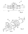
- Figure 2
- shows a side view of the device;
- Figure 3
- shows a perspective view of a first housing part to be connected to a high-pressure line;
- Figure 4
- shows a perspective view of a second housing part to be connected to a return line;
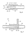
- Figure 5
- shows a section IX-IX from
Figure 4 through the second housing part; - Figure 6
- shows a section X-X from
Figure 3 through the second housing part; - Figure 7
- shows a section XI-XI from
Figure 4 through the second housing part. -
Figure 1 shows a fuel return system for a 4-cylinder engine identified overall as 210 which has a total of four fuel injectors (not shown) to which retainingdevices 212 are clipped. These retainingdevices 212 possessconnectors 214 which engage a matching socket in the fuel injector. The excess fuel which is taken through thereturn lines 216 to be suctioned off is taken to theconnectors 214 through these sockets. Thissuction device 218 is attached by asuitable retaining clip 220 to the engine or in the engine compartment. - As can be seen from
Figure 2 , thesuction device 218 has afirst connection 222 to which a high-pressure line 224 can be connected. Fuel under pressure is transported in this high-pressure line 224 towards thesuction device 218. In a center area of thesuction device 218, there is asecond connection 226 to which thereturn line 216 is connected. Athird connection 228 is provided opposite thefirst connection 222 to which adrain line 230 can be connected. The fuel brought in through the high-pressure line 224 and thereturn line 216 of thesuction device 218 is taken away through thisdrain line 230, for example, to the tank. - The suction device 28 consists of a
housing part 232, shown inFigure 3 , onto which thefirst connection 222 is formed and asecond housing part 234, which is shown inFigure 4 . Thesecond connection 226 and thethird connection 228 project radially or axially from thissecond housing part 234. In addition,areas 236 can be seen in whichhousing ribs 238 are provided running in the longitudinal direction, that is to say axially, to which theretaining clip 220 fastens. - A
fuel injector 240 which is aligned coaxially to thelongitudinal axis 242 of thefirst housing part 232 is provided opposite thefirst connection 222. Thefuel injector 240 is flanked by two retainingarms 244 located opposite each other whose free ends have leadingbevels 248. In addition, the retainingarms 244 are given lockingslots 250 which coact, specifically engage, with lockingtabs 252 on thesecond housing part 234. Theslots 250 and thetabs 252 form retaining means 246 for the retainingarms 244. - It can be seen from
Figure 2 that thefirst housing part 232 has an essentially cartridge-shaped configuration, in which theinjector nozzle 240 extends coaxially and is connected to thefirst connection 222. The injector nozzle possesses anarrow injector opening 254 in which the fluid being carried, specifically the fuel being carried, is accelerated to maximum speed. In the immediate vicinity of this injector opening is the opening 56 of thesecond connection 226 through which the fuel is suctioned off from thereturn line 216 through the negative pressure generated. The exact alignment of theopening 256 relative to thenozzle opening 254 is achieved by astop 258 on thefirst housing part 232 for aninsertion sleeve 260 which is formed coaxially onto thesecond housing part 234 and surrounds the injector nozzle. The diffuser required for the venturi system can be seen in thesecond housing part 234. In addition, twolongitudinal guides 264, which abut the retainingarms 244 laterally when they are latched to the lockingtabs 252, can be seen in the views of the second housing part shown inFigures 6 and 7 . Theselongitudinal guides 264 prevent the twohousing parts - The outlet or opening 256 of the
second connection 226, that is theopening 256 in theflow duct 266 of the venturi system, is shown inFigure 7 . Thisopening 256 lies in a defined position relative to thenozzle opening 254 when thehousing parts - The design of the
device 218 with twohousing parts
Claims (15)
- Device for suctioning fuel from a fuel injector which is connected by way of a return line (216) to the device (218), with a first connection (222) for a high-pressure line (224), a second connection (226) for the return line (216) and a third connection (228) for a drain line (230), wherein the connections (232, 226 and 228) are connected to a venturi system and the first connection (222) opens into an injector nozzle (240) and the second connection (226) opens in the area of the nozzle opening (254), wherein the first connection (222) is formed onto a first housing part (232) of the device (218) and the third connection (228) onto a second housing part (234).
- Device in accordance with claim 1, wherein the injector nozzle (240) is formed onto the first housing part (232).
- Device in accordance with claim 1 or 2, wherein the first housing part (232) is essentially cartridge-shaped and the injector nozzle (240) is located coaxially in the first housing part (232).
- Device in accordance with one of the preceding claims, wherein the second connection (226) is formed onto the first or second housing part (232 or 234).
- Device in accordance with one of the preceding claims, wherein the second housing part (234) has a cartridge-shaped axial extension (260) which encloses the injector nozzle (240).
- Device in accordance with one of the preceding claims, wherein retaining arms (244) extending in the axial direction are provided on the first housing part (232) partially surrounding the second housing part (234), or conversely.
- Device in accordance with claim 6, wherein the retaining arms (244) are configured as locking arms.
- Device in accordance with claim 6 or 7, wherein two oppositely located retaining arms (244) are provided.
- Device in accordance with one of the claims 6 to 8, wherein the second housing part (234) has retaining means (246) for the retaining arms (244).
- Device in accordance with claim 9, wherein the retaining means (246) have locking tabs (252) or locking slots and the retaining arms (244) have locking slots (250) or locking tabs.
- Device in accordance with one of the claims 6 to 10, wherein the second housing part (234) is provided with longitudinal guides (264) for the retaining arms (244).
- Device in accordance with claim 11, wherein the longitudinal guides (264) lie laterally next to the retaining arms (244).
- Device in accordance with claim 11 or 12, wherein at least two longitudinal guides (264) locate a retaining arm (244).
- Device in accordance with one of the claims 11 to 13, wherein the longitudinal guide (234) supports the retaining arm (244) in the peripheral direction.
- Device in accordance with one of the claims 11 to 14, wherein the longitudinal guide (264) is formed by a projection or recess running radially in the longitudinal direction.
Applications Claiming Priority (4)
| Application Number | Priority Date | Filing Date | Title |
|---|---|---|---|
| DE200410058466 DE102004058466B3 (en) | 2004-11-25 | 2004-11-25 | Retaining device for fuel injector used in engine, has base having retaining arms whose free ends are converged and inclined towards base |
| DE200410059343 DE102004059343B3 (en) | 2004-11-29 | 2004-11-29 | Retaining device for fuel injector used in engine, has base having retaining arms whose free ends are converged and inclined towards base |
| DE102004062446A DE102004062446B3 (en) | 2004-12-17 | 2004-12-17 | Attachment for connecting a fuel return line to a fuel injector provides free ends of the retaining arms with a primary section in which they are angled towards each other and towards the base of the main body |
| EP05022768A EP1662132A3 (en) | 2004-11-25 | 2005-10-19 | Device to attach a fuel return line to a fuel injector and device to suction fuel from a fuel injector |
Related Parent Applications (1)
| Application Number | Title | Priority Date | Filing Date |
|---|---|---|---|
| EP05022768A Division EP1662132A3 (en) | 2004-11-25 | 2005-10-19 | Device to attach a fuel return line to a fuel injector and device to suction fuel from a fuel injector |
Publications (2)
| Publication Number | Publication Date |
|---|---|
| EP1903209A1 true EP1903209A1 (en) | 2008-03-26 |
| EP1903209B1 EP1903209B1 (en) | 2009-10-07 |
Family
ID=36631576
Family Applications (2)
| Application Number | Title | Priority Date | Filing Date |
|---|---|---|---|
| EP07024179A Ceased EP1903209B1 (en) | 2004-11-25 | 2005-10-19 | Device to suction fuel from a fuel injector |
| EP05022768A Withdrawn EP1662132A3 (en) | 2004-11-25 | 2005-10-19 | Device to attach a fuel return line to a fuel injector and device to suction fuel from a fuel injector |
Family Applications After (1)
| Application Number | Title | Priority Date | Filing Date |
|---|---|---|---|
| EP05022768A Withdrawn EP1662132A3 (en) | 2004-11-25 | 2005-10-19 | Device to attach a fuel return line to a fuel injector and device to suction fuel from a fuel injector |
Country Status (3)
| Country | Link |
|---|---|
| US (1) | US7331330B2 (en) |
| EP (2) | EP1903209B1 (en) |
| JP (1) | JP2006153015A (en) |
Cited By (3)
| Publication number | Priority date | Publication date | Assignee | Title |
|---|---|---|---|---|
| CN103261683A (en) * | 2010-12-16 | 2013-08-21 | 罗伯特·博世有限公司 | Pump unit for feeding fuel, preferably diesel fuel, from a storage tank to an internal combustion engine |
| US20190048768A1 (en) * | 2016-04-19 | 2019-02-14 | ElringKIinger AG | Ejector device and combination of a cylinder head cover and an ejector device |
| CN111997804A (en) * | 2020-08-21 | 2020-11-27 | 东风汽车股份有限公司 | Venturi tube mounting structure |
Families Citing this family (11)
| Publication number | Priority date | Publication date | Assignee | Title |
|---|---|---|---|---|
| DE10215980B4 (en) * | 2002-04-11 | 2008-03-27 | Siemens Ag | Leakage connection for a fuel injector |
| DE102005016865B4 (en) * | 2005-04-12 | 2006-11-30 | Siemens Ag | Leakage connection and fuel injector with leakage connection |
| DE602006002823D1 (en) * | 2006-08-16 | 2008-10-30 | Delphi Tech Inc | quick coupling |
| DE102007004775A1 (en) * | 2007-01-31 | 2008-08-07 | Audi Ag | Common rail injection system's fuel storage draining method for vehicle i.e. motor vehicle, involves draining fuel storage by extracting fuel, and bringing injection valve into opening position to ventilate system during fuel extraction |
| KR101449760B1 (en) | 2008-09-08 | 2014-10-13 | 타이코에이엠피(유) | Injector double locking connector |
| GB2467321A (en) * | 2009-01-28 | 2010-08-04 | Fluid Transfer Systems Ltd | Snap-fit connector and non-return valve for a fuel injector leak-off line |
| EP2249021A1 (en) * | 2009-05-06 | 2010-11-10 | Delphi Technologies Holding S.à.r.l. | Fuel Delivery System |
| DE102009027459A1 (en) * | 2009-07-03 | 2011-01-05 | Robert Bosch Gmbh | Fuel injector and fuel injection system |
| EP2971748A4 (en) * | 2013-03-15 | 2016-11-30 | United Technologies Corp | Cartridge style ejector pump |
| GB2547010B (en) * | 2016-02-04 | 2019-11-13 | Delphi Tech Ip Ltd | Fuel injectors |
| US11002233B1 (en) * | 2019-11-29 | 2021-05-11 | Caterpillar Inc. | Single-fluid common rail fuel injector with fuel recovery fitting and engine system using same |
Citations (2)
| Publication number | Priority date | Publication date | Assignee | Title |
|---|---|---|---|---|
| US5133324A (en) | 1989-12-13 | 1992-07-28 | Nissan Motor Co., Ltd. | Ejector pump for vehicle fuel tank |
| EP0893598A2 (en) | 1997-07-26 | 1999-01-27 | Lucas Industries Public Limited Company | Fuel system |
Family Cites Families (10)
| Publication number | Priority date | Publication date | Assignee | Title |
|---|---|---|---|---|
| GB2088984B (en) * | 1980-11-22 | 1984-07-04 | Yorkshire Imperial Plastics | Plastics pipe fitting |
| DE59101949D1 (en) * | 1991-07-10 | 1994-07-21 | Gruber Alois Agru Gmbh | Tapping clamp for fluid lines, especially for gas and water. |
| DE9409427U1 (en) | 1994-06-10 | 1995-10-05 | Robert Bosch Gmbh, 70469 Stuttgart | Fuel line connector |
| FR2721088B1 (en) * | 1994-06-10 | 1997-09-12 | Bosch Gmbh Robert | Fuel line connection comprising a nozzle and a device for axially locking it in the connection hole. |
| US5690079A (en) * | 1995-02-24 | 1997-11-25 | Craig; Douglas R. | Apparatus for enhancing fuel efficiency of a vehicle |
| IT1292771B1 (en) * | 1997-06-16 | 1999-02-11 | Elasis Sistema Ricerca Fiat | DEVICE FOR QUICK CONNECTION OF A REFLUX CONNECTOR WITH A FUEL INJECTOR FOR INTERNAL COMBUSTION ENGINES |
| FR2771472B1 (en) * | 1997-11-21 | 2000-01-14 | Renault | SNAP-IN CONNECTION IN PARTICULAR FOR FUEL LINES |
| JP2002202025A (en) * | 2000-11-06 | 2002-07-19 | Auto Network Gijutsu Kenkyusho:Kk | Injector integrated module |
| US6767033B2 (en) * | 2002-10-28 | 2004-07-27 | Lloyd Herbert King, Jr. | Pipe saddle |
| US6830037B1 (en) * | 2004-01-27 | 2004-12-14 | Delphi Technologies, Inc. | Anti-rotation fuel injector clip |
-
2005
- 2005-10-19 EP EP07024179A patent/EP1903209B1/en not_active Ceased
- 2005-10-19 EP EP05022768A patent/EP1662132A3/en not_active Withdrawn
- 2005-11-17 US US11/281,529 patent/US7331330B2/en not_active Expired - Lifetime
- 2005-11-25 JP JP2005340322A patent/JP2006153015A/en not_active Withdrawn
Patent Citations (2)
| Publication number | Priority date | Publication date | Assignee | Title |
|---|---|---|---|---|
| US5133324A (en) | 1989-12-13 | 1992-07-28 | Nissan Motor Co., Ltd. | Ejector pump for vehicle fuel tank |
| EP0893598A2 (en) | 1997-07-26 | 1999-01-27 | Lucas Industries Public Limited Company | Fuel system |
Cited By (5)
| Publication number | Priority date | Publication date | Assignee | Title |
|---|---|---|---|---|
| CN103261683A (en) * | 2010-12-16 | 2013-08-21 | 罗伯特·博世有限公司 | Pump unit for feeding fuel, preferably diesel fuel, from a storage tank to an internal combustion engine |
| US20190048768A1 (en) * | 2016-04-19 | 2019-02-14 | ElringKIinger AG | Ejector device and combination of a cylinder head cover and an ejector device |
| US10982575B2 (en) * | 2016-04-19 | 2021-04-20 | Elringklinger Ag | Ejector device and combination of a cylinder head cover and an ejector device |
| CN111997804A (en) * | 2020-08-21 | 2020-11-27 | 东风汽车股份有限公司 | Venturi tube mounting structure |
| CN111997804B (en) * | 2020-08-21 | 2021-04-23 | 东风汽车股份有限公司 | Venturi tube mounting structure |
Also Published As
| Publication number | Publication date |
|---|---|
| US20060107928A1 (en) | 2006-05-25 |
| EP1903209B1 (en) | 2009-10-07 |
| US7331330B2 (en) | 2008-02-19 |
| EP1662132A2 (en) | 2006-05-31 |
| JP2006153015A (en) | 2006-06-15 |
| EP1662132A3 (en) | 2006-06-07 |
Similar Documents
| Publication | Publication Date | Title |
|---|---|---|
| EP1903209B1 (en) | Device to suction fuel from a fuel injector | |
| US5405175A (en) | Clip attachment of fuel tube to fuel rail | |
| US6182694B1 (en) | Fuel delivery unit having a line connection | |
| US7931007B2 (en) | Fuel-injection device | |
| CN1059487C (en) | Fuel rail assembly | |
| JPH1172066A (en) | Connection device for connecting a backflow connector to an internal combustion engine fuel injection device | |
| CN111373186B (en) | Fluid Line Couplings with Fixing Clamps | |
| US20070216161A1 (en) | Connector for a tubular air conducting element on a turbocharger | |
| EP2058509B1 (en) | Coupling device | |
| JPH10122089A (en) | Fuel supply device and method of manufacturing the same | |
| CN103026047B (en) | Fuel transmission component | |
| US20120060794A1 (en) | Throttle Body To Intake Manifold Mounting | |
| US20090290994A1 (en) | Suction Jet Pump | |
| EP0893598A2 (en) | Fuel system | |
| CN1760530B (en) | Turn lock fuel nozzle assembly | |
| CN107687386A (en) | A kind of fuel injection assemblies for internal combustion engine | |
| JP3846337B2 (en) | Injector fixing method and injector fixing device | |
| CN106104020A (en) | There is the assembly of clamp connection | |
| US20160090954A1 (en) | Connecting device and component group | |
| CN102414430B (en) | Fuel injection valve mounting structure | |
| EP1950483A1 (en) | Connector for circulation, connection structure for connector for circulation, and fuel circulation system | |
| RU2502613C2 (en) | Feed device fastener | |
| US5012784A (en) | Pressure regulator device and fuel line receptor therefor | |
| US20080302430A1 (en) | Backflow Connector and Fuel Injector Having Backflow Connector | |
| JP4181505B2 (en) | Injector with improved connection geometry |
Legal Events
| Date | Code | Title | Description |
|---|---|---|---|
| PUAI | Public reference made under article 153(3) epc to a published international application that has entered the european phase |
Free format text: ORIGINAL CODE: 0009012 |
|
| AC | Divisional application: reference to earlier application |
Ref document number: 1662132 Country of ref document: EP Kind code of ref document: P |
|
| AK | Designated contracting states |
Kind code of ref document: A1 Designated state(s): FR GB |
|
| 17P | Request for examination filed |
Effective date: 20080807 |
|
| 17Q | First examination report despatched |
Effective date: 20080911 |
|
| AKX | Designation fees paid |
Designated state(s): FR GB |
|
| GRAP | Despatch of communication of intention to grant a patent |
Free format text: ORIGINAL CODE: EPIDOSNIGR1 |
|
| RTI1 | Title (correction) |
Free format text: DEVICE TO SUCTION FUEL FROM A FUEL INJECTOR |
|
| GRAS | Grant fee paid |
Free format text: ORIGINAL CODE: EPIDOSNIGR3 |
|
| GRAA | (expected) grant |
Free format text: ORIGINAL CODE: 0009210 |
|
| AC | Divisional application: reference to earlier application |
Ref document number: 1662132 Country of ref document: EP Kind code of ref document: P |
|
| AK | Designated contracting states |
Kind code of ref document: B1 Designated state(s): FR GB |
|
| REG | Reference to a national code |
Ref country code: GB Ref legal event code: FG4D |
|
| PLBE | No opposition filed within time limit |
Free format text: ORIGINAL CODE: 0009261 |
|
| STAA | Information on the status of an ep patent application or granted ep patent |
Free format text: STATUS: NO OPPOSITION FILED WITHIN TIME LIMIT |
|
| 26N | No opposition filed |
Effective date: 20100708 |
|
| REG | Reference to a national code |
Ref country code: FR Ref legal event code: PLFP Year of fee payment: 11 |
|
| REG | Reference to a national code |
Ref country code: FR Ref legal event code: PLFP Year of fee payment: 12 |
|
| REG | Reference to a national code |
Ref country code: FR Ref legal event code: PLFP Year of fee payment: 13 |
|
| REG | Reference to a national code |
Ref country code: FR Ref legal event code: PLFP Year of fee payment: 14 |
|
| PGFP | Annual fee paid to national office [announced via postgrant information from national office to epo] |
Ref country code: GB Payment date: 20211027 Year of fee payment: 17 |
|
| PGFP | Annual fee paid to national office [announced via postgrant information from national office to epo] |
Ref country code: FR Payment date: 20211025 Year of fee payment: 17 |
|
| GBPC | Gb: european patent ceased through non-payment of renewal fee |
Effective date: 20221019 |
|
| PG25 | Lapsed in a contracting state [announced via postgrant information from national office to epo] |
Ref country code: FR Free format text: LAPSE BECAUSE OF NON-PAYMENT OF DUE FEES Effective date: 20221031 |
|
| PG25 | Lapsed in a contracting state [announced via postgrant information from national office to epo] |
Ref country code: GB Free format text: LAPSE BECAUSE OF NON-PAYMENT OF DUE FEES Effective date: 20221019 |