EP1903094B1 - Device for extracting oil from vegetable products - Google Patents
Device for extracting oil from vegetable products Download PDFInfo
- Publication number
- EP1903094B1 EP1903094B1 EP07116827A EP07116827A EP1903094B1 EP 1903094 B1 EP1903094 B1 EP 1903094B1 EP 07116827 A EP07116827 A EP 07116827A EP 07116827 A EP07116827 A EP 07116827A EP 1903094 B1 EP1903094 B1 EP 1903094B1
- Authority
- EP
- European Patent Office
- Prior art keywords
- grinder
- press
- appliance
- vegetable matter
- control means
- Prior art date
- Legal status (The legal status is an assumption and is not a legal conclusion. Google has not performed a legal analysis and makes no representation as to the accuracy of the status listed.)
- Not-in-force
Links
Images

Classifications
-
- B—PERFORMING OPERATIONS; TRANSPORTING
- B30—PRESSES
- B30B—PRESSES IN GENERAL
- B30B9/00—Presses specially adapted for particular purposes
- B30B9/02—Presses specially adapted for particular purposes for squeezing-out liquid from liquid-containing material, e.g. juice from fruits, oil from oil-containing material
- B30B9/04—Presses specially adapted for particular purposes for squeezing-out liquid from liquid-containing material, e.g. juice from fruits, oil from oil-containing material using press rams
- B30B9/06—Presses specially adapted for particular purposes for squeezing-out liquid from liquid-containing material, e.g. juice from fruits, oil from oil-containing material using press rams co-operating with permeable casings or strainers
-
- A—HUMAN NECESSITIES
- A47—FURNITURE; DOMESTIC ARTICLES OR APPLIANCES; COFFEE MILLS; SPICE MILLS; SUCTION CLEANERS IN GENERAL
- A47J—KITCHEN EQUIPMENT; COFFEE MILLS; SPICE MILLS; APPARATUS FOR MAKING BEVERAGES
- A47J19/00—Household machines for straining foodstuffs; Household implements for mashing or straining foodstuffs
- A47J19/02—Citrus fruit squeezers; Other fruit juice extracting devices
- A47J19/025—Citrus fruit squeezers; Other fruit juice extracting devices including a pressing screw
-
- A—HUMAN NECESSITIES
- A47—FURNITURE; DOMESTIC ARTICLES OR APPLIANCES; COFFEE MILLS; SPICE MILLS; SUCTION CLEANERS IN GENERAL
- A47J—KITCHEN EQUIPMENT; COFFEE MILLS; SPICE MILLS; APPARATUS FOR MAKING BEVERAGES
- A47J42/00—Coffee mills; Spice mills
- A47J42/32—Coffee mills; Spice mills with other grinding or pulverising members
- A47J42/34—Coffee mills; Spice mills with other grinding or pulverising members hand driven
-
- B—PERFORMING OPERATIONS; TRANSPORTING
- B30—PRESSES
- B30B—PRESSES IN GENERAL
- B30B1/00—Presses, using a press ram, characterised by the features of the drive therefor, pressure being transmitted directly, or through simple thrust or tension members only, to the press ram or platen
- B30B1/18—Presses, using a press ram, characterised by the features of the drive therefor, pressure being transmitted directly, or through simple thrust or tension members only, to the press ram or platen by screw means
- B30B1/20—Presses, using a press ram, characterised by the features of the drive therefor, pressure being transmitted directly, or through simple thrust or tension members only, to the press ram or platen by screw means driven by hand
-
- B—PERFORMING OPERATIONS; TRANSPORTING
- B30—PRESSES
- B30B—PRESSES IN GENERAL
- B30B11/00—Presses specially adapted for forming shaped articles from material in particulate or plastic state, e.g. briquetting presses, tabletting presses
- B30B11/22—Extrusion presses; Dies therefor
- B30B11/227—Means for dividing the extruded material into briquets
-
- B—PERFORMING OPERATIONS; TRANSPORTING
- B30—PRESSES
- B30B—PRESSES IN GENERAL
- B30B9/00—Presses specially adapted for particular purposes
- B30B9/02—Presses specially adapted for particular purposes for squeezing-out liquid from liquid-containing material, e.g. juice from fruits, oil from oil-containing material
- B30B9/04—Presses specially adapted for particular purposes for squeezing-out liquid from liquid-containing material, e.g. juice from fruits, oil from oil-containing material using press rams
- B30B9/06—Presses specially adapted for particular purposes for squeezing-out liquid from liquid-containing material, e.g. juice from fruits, oil from oil-containing material using press rams co-operating with permeable casings or strainers
- B30B9/065—Presses specially adapted for particular purposes for squeezing-out liquid from liquid-containing material, e.g. juice from fruits, oil from oil-containing material using press rams co-operating with permeable casings or strainers for making briquettes, e.g. from paper
-
- C—CHEMISTRY; METALLURGY
- C11—ANIMAL OR VEGETABLE OILS, FATS, FATTY SUBSTANCES OR WAXES; FATTY ACIDS THEREFROM; DETERGENTS; CANDLES
- C11B—PRODUCING, e.g. BY PRESSING RAW MATERIALS OR BY EXTRACTION FROM WASTE MATERIALS, REFINING OR PRESERVING FATS, FATTY SUBSTANCES, e.g. LANOLIN, FATTY OILS OR WAXES; ESSENTIAL OILS; PERFUMES
- C11B1/00—Production of fats or fatty oils from raw materials
- C11B1/06—Production of fats or fatty oils from raw materials by pressing
Definitions
- the present invention essentially relates to an apparatus for extracting oil from plant material.
- a device for extracting olive oil, peanut, etc. is known from the document FR 581844 .
- This comprises a fixed and mobile nut crusher, ducts in which a crushed plant material descends, and two compressor trays set in motion by a piston supplied with compressed air.
- This olive oil extraction machine, peanut, etc. not only has the disadvantage of being difficult to clean and maintain after use both at the level of the mill and at the level of the compressor trays; but also the disadvantage of not getting the vegetable oil alone.
- this device requires the use of compressed air and therefore a secondary installation without which the device can not operate.
- the main purpose of the invention is to solve the aforementioned problems, that is to say to provide a device of simple design and space-saving, to obtain and isolate a vegetable oil alone.
- Another object of the present invention is to provide an easy-to-maintain appliance whose use does not require any particular device to be put in place beforehand.
- the apparatus according to the invention has the advantage of being usable on an industrial and commercial scale, in a safe and reliable manner and its simple structure makes it possible to obtain an inexpensive manufacturing apparatus.
- the invention solves all of the above technical problems, in a safe and reliable manner, usable on an industrial and commercial scale.
- the invention provides an apparatus for extracting vegetable oil from plant material, as claimed in claims 1 to 15, and comprising a housing in which is mounted successively or alternatively at least a press and a grinder; and comprising at least one decanter, present in the housing; and control means of the mill and the press allowing forced movement of the plant material, at least a portion of the control means and at least a portion of the mill and / or the press being removable for successively controlling the mill and the press.
- one of the control means is a unique means of actuation simplifying the design of the apparatus, such as a manual or motorized mechanism, which can cooperate with either the grinder or with the press.
- the cooperation between the manual or motorized mechanism and the crusher or the press can be carried out by driving one of the control means corresponding to a moving means, such as a screw endless or threaded rod.
- the sole means of operating the crusher and the press corresponds to a manual mechanism consisting of a crank and at least one drive mechanism such as a wheel used to lead to a means of displacement, such as a worm, or threaded rod, mill and / or press.
- the drive mechanism comprises a temporary coupling means with a displacement means consisting of either a worm or threaded rod of the mill, or a worm or threaded rod of the press.
- the coupling means comprises two bevel gears driving a flattened ring.
- the manual mechanism is made at least partly of machined steel or casting.
- the apparatus is provided with at least one security system, preferably a system for blocking one or more control means, such as one or more motorized mechanism (s) when the unit is not properly mounted and closed.
- security system preferably a system for blocking one or more control means, such as one or more motorized mechanism (s) when the unit is not properly mounted and closed.
- the mill is a screw mill, said screw being preferably conical, to drive the plant material downwards.
- the mill comprises at least one grinding means, such as a knife provided with at least one blade, preferably a knife with three or four blades.
- the mill comprises at least one perforated grid, preferably at least two grids having different diameters of perforation, each grid being separated from another by a grinding means such as a knife.
- the mill comprises three grids having different perforation diameters and two knives with a different number of blades, said grids being arranged alternately with said knives.
- the mill comprises a receptacle or receptacle of plant material for containing the plant material to be milled.
- the mill comprises a fastening system, such as a support beam, cooperating with a receptacle or receptacle for the plant material and / or a displacement means constituted by the worm or threaded rod and ensuring a hold in place of said moving means.
- a fastening system such as a support beam
- the fastening system consists of a holding beam and a spring.
- each component of the mill such as the worm, the knife (s), the grid (s), the receptacle of the plant material, the fixing or guiding system is made of either food grade stainless steel or rigid plastic which has the advantage of being moldable.
- the housing comprises a reservoir for receiving crushed and / or pressed plant material, preferably comprising at least one perforated wall serving a filtration of the desired vegetable oil and then constituting the aforementioned decanter.
- the receiving tank of the plant material constitutes a sieve having the shape of a container of any geometry, preferably cylindrical, cubic, having an opening from above, a base or bottom not perforated (e) and one or perforated wall (s), in particular having orifices of about 5 microns in diameter, allowing at least filtration of the desired vegetable oil.
- the press comprises a mountable and / or dismountable plate mounted after actuation of the mill, the displacement of which is controlled by one or more control means comprising at least one moving means. and at least one blocking means.
- the plate moves in translation with the aid of a displacement means constituted by a threaded rod whose end is taken in the thickness of the bottom of the sieve, said plate coming from screw on the other free end of said rod and comprising a locking means for both maintaining the end of the threaded rod taken in the thickness of the bottom of the sieve and screw the tray.
- a displacement means constituted by a threaded rod whose end is taken in the thickness of the bottom of the sieve, said plate coming from screw on the other free end of said rod and comprising a locking means for both maintaining the end of the threaded rod taken in the thickness of the bottom of the sieve and screw the tray.
- the plate comprises at least one notch allowing the plate to be arranged and / or screwed correctly at the top of the sieve.
- each component of the press such as the sieve, the tray, the threaded rod, is made of either food grade stainless steel or food plastic.
- a tool for mounting or dismounting the press platen can be temporarily secured to a translational movement means of the plate, such as at the head of a worm or threaded rod .
- the tool for mounting or dismounting the press platen that can be secured temporarily corresponds to a handle having a flattened ring which can be fixed on the threaded rod taken in the thickness. bottom of the sieve to allow to remove the entire press after use.
- said handle is made of wood, resin, steel or plastic.
- the receiving tank serves as a decanter and has a diameter smaller than the diameter of the housing to define a receiving chamber or decantation at least of the filtered liquid phase.
- the receiving tank serves both as settler and press.
- the decanter formed by the combination of the housing and the receiving tank is provided with at least one emptying means, preferably made on the bottom of the housing, for separating an oil phase from an aqueous phase or to separate an aqueous phase from an oily phase.
- the emptying means corresponds to a tap.
- the decanter is provided with a handle and / or a spout.
- the settling tank has measurement graduations indicating the quantity of liquid.
- the decanter is made of food grade stainless steel or glass.
- the housing comprises a base cooperating with a lateral body defining a receiving chamber in part of the mill and / or the press and the plant material.
- the lateral body constitutes a holding support of the mill.
- the base is made of essentially non-stretchable material, such as wood, resin, steel or plastic.
- the plant material is chosen from the group consisting of wood nuts, seeds, and whole oleiferous drupes including skins, pulp and almond-containing cores.
- whole oleiferous drupes are fresh whole olives, or whole fresh avocados.
- only the kernel of drupes or woody nuts, such as walnut kernels, is used to make oil.
- the method is used on plant materials as previously defined.
- the invention further covers the use of the previously defined apparatus for extracting vegetable oil from plant material in the field of food preparation apparatus as claimed in claim 18.
- the invention as defined above and as resulting from the description of the figures below, representing a presently preferred embodiment of the invention, makes it possible to solve the technical problems previously stated for the purposes of the invention and thus allows to achieve an apparatus for extracting vegetable oil from plant material, safely and reliably, usable on an industrial and commercial scale.
- the device is completely removable and can be easily cleaned.
- the apparatus 10 for extracting oil from plant material comprises a housing 20 in which is mounted successively a mill 30 and a press 60 comprising a worm 31b mounted with a rod 31a; and a decanter 80, preferably present in the housing 20 and at least one control means 31a, 31b, 40, 61, 64a, 64b of the mill 30 and the press 60 for forced displacement of the plant material, preferably at least a portion of the control means 31a, 31b, 40, 61, 64a, 64b and at least a portion of the mill 30 and / or press 60 being removable to successively control the mill 30 and the press 60.
- One of the control means is a single actuating means 40 simplifying the design of the apparatus. This corresponds to a manual mechanism 40 which can cooperate with a displacement means 31a, 31b, 61, such as a worm 31 of the mill 30 or a threaded rod 61 of the press 60.
- Said manual mechanism 40 is composed of a crank 41 and at least one drive mechanism 42, here two bevel gears 42 for driving the rotation of a temporary coupling means 43, such as in the present case a flattened ring 43 and simultaneously a displacement means, here, either the worm 31 of the mill 30, or the threaded rod of the press taken in the temporary coupling means 43.
- This single actuating means 40 is equipped with a closure system, here constituted by two screws 44a, 44b which are inserted either in both orifices 45a, 45b of the manual mechanism 40, into orifices 37a, 37b of a fastening system described hereinafter disposed between the manual mechanism and the mill and in the orifices 39a, 39b of the mill, either in the orifices 45a, 45b of the manual mechanism 40 and in the orifices 21a, 21b of the housing.
- a closure system here constituted by two screws 44a, 44b which are inserted either in both orifices 45a, 45b of the manual mechanism 40, into orifices 37a, 37b of a fastening system described hereinafter disposed between the manual mechanism and the mill and in the orifices 39a, 39b of the mill, either in the orifices 45a, 45b of the manual mechanism 40 and in the orifices 21a, 21b of the housing.
- the single actuating means 40 can be made in the form of a motorized mechanism and provide a security system for blocking one or more control means, such as one or more mechanisms ( s) motorized (s) when the unit is not properly mounted and closed.
- the manual mechanism 40 may be made at least partly of machined steel or casting.
- the apparatus 10 shown in FIGS. figures 1 and 2 essentially involves its upper part consisting of said manual mechanism 40 previously described and the mill 30.
- Said mill 30 comprises a fastening system 37, here constituted by a retaining crossmember and a spring, cooperating with a receptacle or receptacle 32 of the plant material and a displacement means constituted by a rod 31a of the screw endless mill 31b; and thus ensuring a maintenance in place of said worm 31.
- Said fastening system 37 is disposed between the mill 30 and the single actuating means 40. It will be noted that the worm 31 has two distinct parts, namely a part upper constituting the rod 31a smooth and a lower portion constituting a conical screw.
- the mill is provided with lateral bodies 38, here three feet 38a, 38b, 38c, located at 120 ° from each other, allowing the mill to remain stable in a vertical position.
- Said lateral body 38 thus constitutes a support for maintaining said mill 30.
- Fresh whole olives 50a can be introduced into the apparatus 10 either directly into the receiving tray 32 of the mill 30, or through a single opening or a chimney, not shown here, of said manual mechanism 40, said single opening or chimney being located in an area that does not interfere with the operation of said manual mechanism.
- the receiving tray 32 of the mill illustrated in figures 1 and 2 , has the distinction of being mountable or removable and is provided with a double wall. However, it should be noted that it can also be achieved with a single wall mountable or removable.
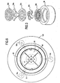
- the worm 31 of the mill ensures the supply of olives 50a to grinding members, illustrated in FIGS. Figures 1 to 3 , composed of several grinding means 34a, 34b, here two knives 34a, 34b and three perforated grids 33a, 33b, 33c having different diameters of perforation.
- the knives 34a, 34b and grids 33a, 33b, 33c are arranged alternately so that each knife 34a, 34b is sandwiched between two grids 33a, 33b, 33c and so that that the grids having large diameters 33a perforation and the knives 34a having fewer blades are placed upstream of the end of the worm and the grids 33c having smaller diameters of perforation and the knives 34b having a more blades are placed downstream of the end of the worm 31.
- the figure 3 shows that the grid 33a having the largest diameter of perforation is located upstream of the end of the worm and the knife 34a having the least blades, here a knife with three blades 34a and the gate 33c having the smaller diameter of the perforations and the four-blade knife 34b are located downstream.
- Such an arrangement of grids 33a, 33b, 33c and knives 34a, 34b makes it possible to grind the vegetable matter progressively, here the fresh whole olives, by reducing the size of the ground vegetable matter.
- the grids and knives cooperate with the worm 31 with a holding member 35 which keeps these grids 33a, 33b, 33c and knives 34a, 34b against the screw.
- This holding element 35 is fixed by screwing to a housing element 36 in which the screw 31 is placed.
- Each component of the mill 30, such as the concentric screw 31, the knife (s) 34a, 34b, the grid (s) 33a, 33b, 33c, the receptacle 32 of the plant material, the fastening system 37 or guide, can be made either of food grade stainless steel or rigid plastic which has the advantage of being able to be molded.
- the crushed olives fall into a housing 20 and more specifically into a receiving tank 62 of crushed and / or pressed plant material, preferably comprising at least one perforated wall used for filtration of the crushed olives.
- vegetable oil sought and constituting a decanter.
- Said receiving tank 62 here constitutes a screen 62 having the shape of a container of any geometry, preferably cylindrical, cubic, having an opening from above, a base or non-perforated bottom (e) and one or walls (s) ) perforated (s), in particular having orifices of about 5 microns in diameter, allowing at least filtration of the desired vegetable oil.
- the press 60 After operating the mill and once all the olives have been milled and joined in the receiving tank 62, the press 60 is provided with a plate mountable and / or removable, whose movement is controlled by several control means comprising at least one moving means 61 and at least one locking means 64a, 64b; then the single actuating means 40 which is fixed with the aid of the aforementioned closure system constituted here by the two screws 44a, 44b which are inserted either in the orifices 45a, 45b of the manual mechanism 40 and in the openings 21a, 21b of the housing.
- the crushed olives 50b can finally be pressed by operating the manual mechanism 40.
- the plate 63 of the press then moves in translation with the aid of a displacement means constituted by the threaded rod 61 of the press whose end is taken in the bottom thickness of the screen, said plate 63 being screwed onto the other free end of said rod 61 and comprising a locking means 64a, 64b allowing both to maintain the end of the threaded rod taken in the thickness of the bottom of the sieve and to screw the tray 63.
- the tray being machined or molded has at least one notch, preferably 5 mm, allowing the tray to be arranged and / or screwed correctly to the top of the screen, preferably about 2.5 cm from the top of the sieve.
- Each component of the press 60 such as the sieve 62, the plate 63, the threaded rod 61, can be made of either food grade stainless steel or food plastic.
- the plate 63 of the press presses the crushed olives 50b against the bottom of the sieve 62.
- Said sieve 62 retains a cake or cake, or more commonly called pomace, constituted by the residues of crushed and pressed olives 50c and passes an aqueous and oily liquid corresponding respectively to the vegetation water or vegetable waters 51 and the desired vegetable oil 52.
- This aqueous and oily liquid is then collected in the casing 20 which has a diameter greater than the diameter of the receiving tank 62, said receiving tank 62 defining a reception or decantation chamber at least filtered aqueous and oily liquid.
- the receiving tank 62 thus serves both as a press 60 when it is provided with the plate 63 and partly as a decanter 80.
- the entire press 60 that is to say the receiving reservoir 62, the tray 63 and the means of Moving and locking the tray, such as the threaded rod 61 and the locking system 64a, 64b, can be removed by means of a tool for mounting or dismounting 65 of the tray.
- Said assembly or disassembly tool 65 of the plate here consisting of a handle 65 comprising a flattened ring 66, is temporarily secured by means of translational movement of the plate, here the threaded rod 61 of which one end is taken in the thickness of the bottom of the sieve 62; and thus allows to remove the entire press after use.
- Said handle 65 can be made of wood, resin, steel or plastic.
- the decanter 80 which can be made of food grade stainless steel or glass, is formed by the combination of the housing 20 and the receiving tank 62. In addition, it can be provided with at least one emptying means 81a, 81b made on one of the decanter walls 80 at any height of the decanter, but preferably in the lower part of the decanter and more preferably at the bottom of the decanter or on the bottom of the housing. These emptying means 81a, 81b, for separating an oily phase from an aqueous phase or separating an aqueous phase from an oily phase, correspond here to valves 81a, 81b.
- the decanter 80 could be provided to provide the decanter 80 with a handle and / or spout and measuring graduations indicating the amount of liquid.
- the housing 20 comprises a base 100 cooperating with the lateral bodies 38a, 38b, 38c, here three feet, defining a receiving chamber in part of the mill and / or the press and the plant material.
- the base can be made of substantially non-stretchable material, such as wood, resin, steel or plastic.
- the device can be used to treat not only fresh whole olives but also other whole oleaginous drupes such as fresh whole avocados or some of the drupes such as almond drupes or woody nuts such as hazelnuts, almonds , and glitches.
- other whole oleaginous drupes such as fresh whole avocados or some of the drupes such as almond drupes or woody nuts such as hazelnuts, almonds , and glitches.
- the previously defined apparatus for extracting vegetable oil from plant material is preferably used in the field of food preparation apparatus.
- the invention provides the previously defined apparatus for extracting and isolating vegetable oil from plant material and effectively resolves the technical problems stated.
- the apparatus according to the invention has the advantage of being uncomplicated to implement, on the one hand by its simple structure design, on the other hand by its practical use requiring no special prior installation and allowing easily maintain the device.
Abstract
Description
La présente invention concerne essentiellement un appareil servant à extraire de l'huile à partir de matière végétale.The present invention essentially relates to an apparatus for extracting oil from plant material.
Un appareil d'extraction d'huile d'olive, d'arachide, etc est connu du document
L'invention a pour but principal de résoudre les problèmes précités, c'est-à-dire de fournir un appareil de conception simple et peu encombrant, permettant d'obtenir et d'isoler une huile végétale seule. La présente invention a aussi pour but principal de réaliser un appareil facile à entretenir dont l'utilisation ne nécessite aucun dispositif particulier à mettre en place au préalable. De plus, l'appareil selon l'invention présente l'avantage d'être utilisable à l'échelle industrielle et commerciale, de manière sûre et fiable et sa structure simple permet d'obtenir un appareil de fabrication peu coûteux.The main purpose of the invention is to solve the aforementioned problems, that is to say to provide a device of simple design and space-saving, to obtain and isolate a vegetable oil alone. Another object of the present invention is to provide an easy-to-maintain appliance whose use does not require any particular device to be put in place beforehand. In addition, the apparatus according to the invention has the advantage of being usable on an industrial and commercial scale, in a safe and reliable manner and its simple structure makes it possible to obtain an inexpensive manufacturing apparatus.
L'invention résout l'ensemble des problèmes techniques ci-dessus, d'une manière sûre et fiable, utilisable à l'échelle industrielle et commerciale.The invention solves all of the above technical problems, in a safe and reliable manner, usable on an industrial and commercial scale.
Ainsi, selon un premier aspect, l'invention fournit un appareil servant à extraire de l'huile végétale à partir de matière végétale, tel que revendiqué dans les revendications 1 à 15, et comprenant un boîtier dans lequel est monté successivement ou alternativement au moins un pressoir et un broyeur ; et comprenant au moins un décanteur, présent dans le boîtier ; et des moyens de commande du broyeur et du pressoir permettant un déplacement forcé de la matière végétale, au moins une partie des moyens de commandes et au moins une partie du broyeur et/ou du pressoir étant démontables pour commander successivement le broyeur et le pressoir.Thus, according to a first aspect, the invention provides an apparatus for extracting vegetable oil from plant material, as claimed in
Selon un mode de réalisation avantageux de l'invention, un des moyens de commande est un moyen unique d'actionnement simplifiant la conception de l'appareil, tel qu'un mécanisme manuel ou motorisé, qui peut coopérer soit avec le broyeur, soit avec le pressoir.According to an advantageous embodiment of the invention, one of the control means is a unique means of actuation simplifying the design of the apparatus, such as a manual or motorized mechanism, which can cooperate with either the grinder or with the press.
Selon une variante particulière de l'invention, la coopération entre le mécanisme manuel ou motorisé et le broyeur ou le pressoir peut s'effectuer par l'entraînement d'un des moyens de commande correspondant à un moyen de déplacement, tel qu'une vis sans fin ou une tige filetée.According to a particular variant of the invention, the cooperation between the manual or motorized mechanism and the crusher or the press can be carried out by driving one of the control means corresponding to a moving means, such as a screw endless or threaded rod.
Selon un autre mode de réalisation avantageux de l'invention, le moyen unique d'actionnement du broyeur et du pressoir correspond à un mécanisme manuel composé d'une manivelle et d'au moins un mécanisme d'entraînement tel qu'une roue servant à entraîner un moyen de déplacement, tel qu'une vis sans fin, ou tige filetée, du broyeur et/ou du pressoir.According to another advantageous embodiment of the invention, the sole means of operating the crusher and the press corresponds to a manual mechanism consisting of a crank and at least one drive mechanism such as a wheel used to lead to a means of displacement, such as a worm, or threaded rod, mill and / or press.
Selon encore un autre mode de réalisation avantageux de l'invention, le mécanisme d'entraînement comprend un moyen de couplage provisoire avec un moyen de déplacement constitué soit d'une vis sans fin ou tige filetée du broyeur, soit d'une vis sans fin ou tige filetée du pressoir.According to yet another advantageous embodiment of the invention, the drive mechanism comprises a temporary coupling means with a displacement means consisting of either a worm or threaded rod of the mill, or a worm or threaded rod of the press.
Selon un mode de réalisation particulier de l'invention, le moyen de couplage comprend deux pignons coniques entraînant une bague méplatée.According to a particular embodiment of the invention, the coupling means comprises two bevel gears driving a flattened ring.
Selon une variante de réalisation de l'invention, le mécanisme manuel est réalisé au moins en partie en acier usiné ou en pièce de fonderie.According to an alternative embodiment of the invention, the manual mechanism is made at least partly of machined steel or casting.
Selon une variante de réalisation particulière de l'invention, l'appareil est muni d'au moins un système de sécurité, de préférence d'un système permettant de bloquer un ou plusieurs moyen(s) de commande, tel qu'un ou des mécanisme(s) motorisé(s) lorsque l'appareil n'est pas correctement monté et fermé.According to a particular embodiment of the invention, the apparatus is provided with at least one security system, preferably a system for blocking one or more control means, such as one or more motorized mechanism (s) when the unit is not properly mounted and closed.
Selon un mode de réalisation avantageux de l'invention, le broyeur est un broyeur à vis sans fin, ladite vis étant de préférence conique, afin d'entraîner la matière végétale vers le bas.According to an advantageous embodiment of the invention, the mill is a screw mill, said screw being preferably conical, to drive the plant material downwards.
Selon un autre mode de réalisation avantageux de l'invention, le broyeur comprend au moins un moyen de broyage, tel qu'un couteau muni d'au moins une lame, de préférence d'un couteau à trois ou quatre lames.According to another advantageous embodiment of the invention, the mill comprises at least one grinding means, such as a knife provided with at least one blade, preferably a knife with three or four blades.
Selon encore un autre mode de réalisation avantageux de l'invention, le broyeur comprend au moins une grille perforée, de préférence au moins deux grilles présentant des diamètres de perforation différents, chaque grille étant séparée d'une autre par un moyen de broyage tel qu'un couteau.According to yet another advantageous embodiment of the invention, the mill comprises at least one perforated grid, preferably at least two grids having different diameters of perforation, each grid being separated from another by a grinding means such as a knife.
Selon une variante de réalisation particulièrement avantageuse de l'invention, le broyeur comporte trois grilles présentant des diamètres de perforation différents et deux couteaux avec un nombre de lames différent, lesdites grilles étant disposées en alternance avec lesdits couteaux.According to a particularly advantageous embodiment of the invention, the mill comprises three grids having different perforation diameters and two knives with a different number of blades, said grids being arranged alternately with said knives.
Selon un mode de réalisation avantageux de l'invention, le broyeur comprend un récipient ou bac récepteur de la matière végétale permettant de contenir la matière végétale à broyer.According to an advantageous embodiment of the invention, the mill comprises a receptacle or receptacle of plant material for containing the plant material to be milled.
Selon un autre mode de réalisation avantageux de l'invention, le broyeur comprend un système de fixation, tel qu'une traverse de maintien, venant coopérer avec un récipient ou bac récepteur de la matière végétale et/ou un moyen de déplacement constitué par la vis sans fin ou tige filetée et assurant un maintien en place dudit moyen de déplacement.According to another advantageous embodiment of the invention, the mill comprises a fastening system, such as a support beam, cooperating with a receptacle or receptacle for the plant material and / or a displacement means constituted by the worm or threaded rod and ensuring a hold in place of said moving means.
Selon encore un autre mode de réalisation avantageux de l'invention, le système de fixation est constitué d'une traverse de maintien et d'un ressort.According to yet another advantageous embodiment of the invention, the fastening system consists of a holding beam and a spring.
Selon une variante de réalisation particulière, chaque composant du broyeur, tel que la vis sans fin, le ou les couteau(x), la ou les grille(s), le bac récepteur de la matière végétale, le système de fixation ou de guidage, est réalisé soit en inox alimentaire soit en matière plastique rigide qui présente l'avantage de pouvoir être moulée.According to a particular embodiment, each component of the mill, such as the worm, the knife (s), the grid (s), the receptacle of the plant material, the fixing or guiding system is made of either food grade stainless steel or rigid plastic which has the advantage of being moldable.
Selon un mode de réalisation de l'invention, le boîtier comprend un réservoir de réception de la matière végétale broyée et/ou pressée, de préférence comprenant au moins une paroi perforée servant à une filtration de l'huile végétale recherchée et constituant alors le décanteur précité.According to one embodiment of the invention, the housing comprises a reservoir for receiving crushed and / or pressed plant material, preferably comprising at least one perforated wall serving a filtration of the desired vegetable oil and then constituting the aforementioned decanter.
Selon un autre mode de réalisation de l'invention, le réservoir de réception de la matière végétale constitue un tamis ayant la forme d'un récipient de géométrie quelconque, de préférence cylindrique, cubique, présentant une ouverture par le haut, une base ou fond non perforé(e) et une ou des paroi(s) perforée(s), en particulier présentant des orifices d'environ 5 microns de diamètre, permettant au moins la filtration de l'huile végétale recherchée.According to another embodiment of the invention, the receiving tank of the plant material constitutes a sieve having the shape of a container of any geometry, preferably cylindrical, cubic, having an opening from above, a base or bottom not perforated (e) and one or perforated wall (s), in particular having orifices of about 5 microns in diameter, allowing at least filtration of the desired vegetable oil.
Selon encore un autre mode de réalisation de l'invention, le pressoir comprend un plateau montable et/ou démontable monté après actionnement du broyeur, dont le déplacement est commandé par un ou des moyen(s) de commande comprenant au moins un moyen de déplacement et au moins un moyen de blocage.According to yet another embodiment of the invention, the press comprises a mountable and / or dismountable plate mounted after actuation of the mill, the displacement of which is controlled by one or more control means comprising at least one moving means. and at least one blocking means.
Selon un mode de réalisation avantageux de l'invention, le plateau se déplace en translation à l'aide d'un moyen de déplacement constitué par une tige filetée dont une extrémité est prise dans l'épaisseur du fond du tamis, ledit plateau venant se visser sur l'autre extrémité libre de ladite tige et comprenant un moyen de blocage permettant à la fois de maintenir l'extrémité de la tige filetée prise dans l'épaisseur du fond du tamis et de visser le plateau.According to an advantageous embodiment of the invention, the plate moves in translation with the aid of a displacement means constituted by a threaded rod whose end is taken in the thickness of the bottom of the sieve, said plate coming from screw on the other free end of said rod and comprising a locking means for both maintaining the end of the threaded rod taken in the thickness of the bottom of the sieve and screw the tray.
Selon un mode de réalisation particulier de l'invention, le plateau comporte au moins une encoche permettant au plateau d'être disposé et/ou vissé correctement en haut du tamis.According to a particular embodiment of the invention, the plate comprises at least one notch allowing the plate to be arranged and / or screwed correctly at the top of the sieve.
Selon un autre mode de réalisation particulier, chaque composant du pressoir, tel que le tamis, le plateau, la tige filetée, est réalisé soit en inox alimentaire soit en plastique alimentaire.According to another particular embodiment, each component of the press, such as the sieve, the tray, the threaded rod, is made of either food grade stainless steel or food plastic.
Selon un autre mode de réalisation avantageux de l'invention, un outil de montage ou démontage du plateau du pressoir peut se solidariser temporairement avec un moyen de déplacement en translation du plateau, tel qu'en tête d'une vis sans fin ou tige filetée.According to another advantageous embodiment of the invention, a tool for mounting or dismounting the press platen can be temporarily secured to a translational movement means of the plate, such as at the head of a worm or threaded rod .
Selon encore un autre mode de réalisation avantageux de l'invention, l'outil de montage ou de démontage du plateau du pressoir pouvant se solidariser temporairement correspond à une poignée comportant une bague méplatée qui peut se fixer sur la tige filetée prise dans l'épaisseur du fond du tamis pour permettre d'enlever l'ensemble du pressoir après son utilisation.According to yet another advantageous embodiment of the invention, the tool for mounting or dismounting the press platen that can be secured temporarily corresponds to a handle having a flattened ring which can be fixed on the threaded rod taken in the thickness. bottom of the sieve to allow to remove the entire press after use.
Selon un mode de réalisation particulier de l'invention, ladite poignée est réalisée en bois, résine, acier ou plastique.According to a particular embodiment of the invention, said handle is made of wood, resin, steel or plastic.
Selon un mode de réalisation avantageux de l'invention, le réservoir de réception sert de décanteur et présente un diamètre inférieur au diamètre du boîtier pour définir une chambre de réception ou décantation au moins de la phase liquide filtrée.According to an advantageous embodiment of the invention, the receiving tank serves as a decanter and has a diameter smaller than the diameter of the housing to define a receiving chamber or decantation at least of the filtered liquid phase.
Selon un autre mode de réalisation avantageux de l'invention, le réservoir de réception sert à la fois de décanteur et de pressoir.According to another advantageous embodiment of the invention, the receiving tank serves both as settler and press.
Selon encore un autre mode de réalisation particulier, le décanteur formé par la combinaison du boîtier et du réservoir de réception est muni d'au moins un moyen de vidange, de préférence réalisé sur le fond du boîtier, permettant de séparer une phase huileuse d'une phase aqueuse ou de séparer une phase aqueuse d'une phase huileuse.According to yet another particular embodiment, the decanter formed by the combination of the housing and the receiving tank is provided with at least one emptying means, preferably made on the bottom of the housing, for separating an oil phase from an aqueous phase or to separate an aqueous phase from an oily phase.
Selon une variante de réalisation de l'invention, le moyen de vidange correspond à un robinet.According to an alternative embodiment of the invention, the emptying means corresponds to a tap.
Selon une autre variante de réalisation de l'invention, le décanteur est muni d'une poignée et/ou d'un bec verseur.According to another embodiment of the invention, the decanter is provided with a handle and / or a spout.
Selon encore une autre variante de réalisation de l'invention, le décanteur présente des graduations de mesure indiquant la quantité de liquide.According to yet another variant embodiment of the invention, the settling tank has measurement graduations indicating the quantity of liquid.
Selon un mode de réalisation particulier de l'invention, le décanteur est réalisé en inox alimentaire ou verre.According to a particular embodiment of the invention, the decanter is made of food grade stainless steel or glass.
Selon un mode de réalisation avantageux de l'invention, le boîtier comprend un socle coopérant avec un corps latéral définissant une chambre de réception en partie du broyeur et/ou du pressoir et de la matière végétale.According to an advantageous embodiment of the invention, the housing comprises a base cooperating with a lateral body defining a receiving chamber in part of the mill and / or the press and the plant material.
Selon un autre mode de réalisation avantageux de l'invention, le corps latéral constitue un support de maintien du broyeur.According to another advantageous embodiment of the invention, the lateral body constitutes a holding support of the mill.
Selon un mode de réalisation particulier de l'invention, le socle est réalisé en matériau essentiellement non extensible, tel que le bois, la résine, l'acier ou encore le plastique.According to a particular embodiment of the invention, the base is made of essentially non-stretchable material, such as wood, resin, steel or plastic.
Selon un mode de réalisation avantageux de l'invention, la matière végétale est choisie parmi le groupe consistant de fruits à coques ligneuses, de pépins, et de drupes oléifères entières comprenant des peaux, de la pulpe et des noyaux contenant des amandes.According to an advantageous embodiment of the invention, the plant material is chosen from the group consisting of wood nuts, seeds, and whole oleiferous drupes including skins, pulp and almond-containing cores.
Selon un autre mode de réalisation avantageux de l'invention, les drupes oléifères entières sont des olives entières fraîches, ou des avocats entiers frais.According to another advantageous embodiment of the invention, whole oleiferous drupes are fresh whole olives, or whole fresh avocados.
Selon encore un autre mode de réalisation avantageux de l'invention, seule l'amande des drupes ou fruits à coques ligneuses, tel que les cerneaux de noix, est utilisé pour fabriquer de l'huile.According to yet another advantageous embodiment of the invention, only the kernel of drupes or woody nuts, such as walnut kernels, is used to make oil.
Selon un deuxième aspect, l'invention couvre aussi un procédé d'extraction d'huile végétale à partir de matière végétale, tel que revendiqué dans les revendications 16, 17, et caractérisé en ce qu'il comprend :
- a) un broyage des matières végétales effectué à l'aide d'un broyeur précédemment défini commandé par des moyens de commande du broyeur,
- b) un démontage d'au moins une partie des moyens de commande du broyeur,
- c) une mise en place de ladite au moins une partie des moyens de commande du broyeur sur un pressoir tel que précédemment défini,
- d) un pressage des matières végétales broyées et une filtration simultanée permettant de séparer un gâteau ou tourteau constitué par les résidus des matières végétales broyées et pressées, un liquide aqueux et huileux résultant du pressage, lesdites opérations de pressage et de filtration étant effectuées à l'aide dudit pressoir commandé par des moyens de commande du pressoir,
- e) une décantation de la phase huileuse et aqueuse effectuée à l'aide d'un décanteur précédemment défini,
- f) séparation de la phase huileuse et de la phase aqueuse après décantation.
- a) a grinding of the vegetable matter carried out using a previously defined mill controlled by the control means of the mill,
- b) disassembly of at least a portion of the grinder control means,
- c) an implementation of said at least a portion of the grinder control means on a press as previously defined,
- d) a pressing of the crushed plant material and a simultaneous filtration for separating a cake or cake consisting of the residues of crushed and pressed vegetable matter, an aqueous and oily liquid resulting from pressing, said pressing and filtration operations being carried out at using said press controlled by control means of the press,
- e) a decantation of the oily and aqueous phase carried out using a previously defined clarifier,
- f) separation of the oily phase and the aqueous phase after decantation.
Selon un mode de réalisation avantageux de l'invention, le procédé est utilisé sur des matières végétales comme précédemment définies.According to an advantageous embodiment of the invention, the method is used on plant materials as previously defined.
Selon un troisième aspect, l'invention couvre encore l'utilisation de l'appareil précédemment défini servant à extraire de l'huile végétale à partir de matière végétale dans le domaine des appareils de préparation culinaire, tel que revendiqué dans la revendication 18.According to a third aspect, the invention further covers the use of the previously defined apparatus for extracting vegetable oil from plant material in the field of food preparation apparatus as claimed in claim 18.
L'invention telle que précédemment définie et telle que résultant de la description des figures ci-après représentant un mode de réalisation actuellement préféré de l'invention, permet de résoudre les problèmes techniques précédemment énoncés dans les buts de l'invention et permet donc de réaliser un appareil servant à extraire de l'huile végétale à partir de matière végétale, de manière sûre et fiable, utilisable à l'échelle industrielle et commerciale. En particulier, l'appareil est entièrement démontable et peut être facilement nettoyé.The invention as defined above and as resulting from the description of the figures below, representing a presently preferred embodiment of the invention, makes it possible to solve the technical problems previously stated for the purposes of the invention and thus allows to achieve an apparatus for extracting vegetable oil from plant material, safely and reliably, usable on an industrial and commercial scale. In particular, the device is completely removable and can be easily cleaned.
D'autres buts, caractéristiques et avantages de l'invention apparaîtront clairement à la lumière de la description explicative qui va suivre, faite en référence au mode de réalisation actuellement préféré de l'invention, faisant partie intégrante de l'invention mais donné simplement à titre d'illustration et qui ne saurait en aucune façon limiter la portée de l'invention.Other objects, features and advantages of the invention will become apparent in light of the following explanatory description, with reference to the presently preferred embodiment of the invention, being an integral part of the invention but simply given to illustrative and that in no way limit the scope of the invention.
-
La
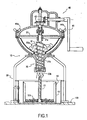
figure 1 représente une vue en coupe longitudinale de l'appareil servant à extraire de l'huile à partir de matière végétale selon la présente invention et selon un mode de réalisation actuellement préféré ;Thefigure 1 is a longitudinal sectional view of the apparatus for extracting oil from plant material according to the present invention and according to a presently preferred embodiment; -
La
figure 2 correspond à une vue en coupe longitudinale du broyeur pris dans son ensemble et du moyen unique d'actionnement constitué ici par un mécanisme manuel présentant une manivelle, un mécanisme d'entraînement, ainsi qu'un moyen de couplage ;Thefigure 2 is a longitudinal sectional view of the mill as a whole and the single actuating means constituted by a manual mechanism having a crank, a drive mechanism, and a coupling means; -
La
figure 3 représente une vue éclatée selon la flèche III des moyens de broyage et des grilles perforées du broyeur.Thefigure 3 represents an exploded view along arrow III of the grinding means and perforated grids of the mill. -
La
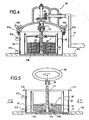
figure 4 représente une vue en coupe longitudinale du décanteur formé par la combinaison du boîtier et du réservoir de réception de la matière végétale broyée et des éléments constituant le pressoir, tels qu'un plateau et des moyens de déplacement et de blocage, ledit pressoir étant muni du moyen unique d'actionnement constitué ici par le mécanisme manuel présentant une manivelle, un mécanisme d'entraînement, ainsi qu'un moyen de couplage ;Thefigure 4 represents a longitudinal sectional view of the settler formed by the combination of the housing and the receiving tank of the ground vegetable material and the elements constituting the press, such as a plate and moving and blocking means, said press being provided with the unique means of actuation here by the manual mechanism having a crank, a drive mechanism, and a coupling means; -
La
figure 5 correspond à une vue en coupe longitudinale du décanteur comme précédemment décrit présentant un moyen de déplacement en translation du plateau, ici une tige filetée, sur lequel vient se solidariser temporairement un outil de montage ou démontage du plateau du pressoir, tel qu'ici une poignée.Thefigure 5 corresponds to a longitudinal sectional view of the clarifier as previously described having means for translational movement of the plate, here a threaded rod, on which is temporarily secured a tool for mounting or dismounting the press plate, such as here a handful . -
La
figure 6 représente une vue en coupe transversale selon l'axe VI-VI du décanteur et du pressoir.Thefigure 6 represents a cross-sectional view along the axis VI-VI of the decanter and the press.
En référence aux
Comme illustré dans la
L'un des moyens de commande est un moyen unique d'actionnement 40 simplifiant la conception de l'appareil. Celui-ci correspond à un mécanisme manuel 40 qui peut coopérer avec un moyen de déplacement 31a, 31b, 61, tel qu'une vis sans fin 31 du broyeur 30 ou une tige filetée 61 du pressoir 60.One of the control means is a single actuating means 40 simplifying the design of the apparatus. This corresponds to a
Ledit mécanisme manuel 40 est composé d'une manivelle 41 et d'au moins un mécanisme d'entraînement 42, ici deux pignons coniques 42 permettant d'entraîner la rotation d'un moyen de couplage provisoire 43, tel que dans le cas présent une bague méplatée 43 et de manière simultanée un moyen de déplacement, ici, soit la vis sans fin 31 du broyeur 30, soit la tige filetée du pressoir prise dans le moyen de couplage provisoire 43.Said
Ce moyen unique d'actionnement 40 est équipé d'un système de fermeture, ici constitué par deux vis 44a, 44b venant s'insérer soit à la fois dans des orifices 45a, 45b du mécanisme manuel 40, dans des orifices 37a, 37b d'un système de fixation décrit ci-après disposé entre le mécanisme manuel et le broyeur ainsi que dans des orifices 39a, 39b du broyeur, soit à la fois dans des orifices 45a, 45b du mécanisme manuel 40 et dans des orifices 21a, 21b du boîtier.This single actuating means 40 is equipped with a closure system, here constituted by two
On peut aussi prévoir que le moyen unique d'actionnement 40 peut être réalisé sous la forme d'un mécanisme motorisé et prévoir un système de sécurité permettant de bloquer un ou plusieurs moyen(s) de commande, tel qu'un ou des mécanisme(s) motorisé(s) lorque l'appareil n'est pas correctement monté et fermé.It can also be provided that the single actuating means 40 can be made in the form of a motorized mechanism and provide a security system for blocking one or more control means, such as one or more mechanisms ( s) motorized (s) when the unit is not properly mounted and closed.
Le mécanisme manuel 40 peut être réalisé au moins en partie en acier usinée ou en pièce de fonderie.The
Dans un premier temps, l'appareil 10 représenté aux
Ledit broyeur 30 comprend un système de fixation 37, constitué ici d'une traverse de maintien et d'un ressort, venant coopérer avec un récipient ou bac récepteur 32 de la matière végétale et un moyen de déplacement constitué par une tige 31a de la vis sans fin 31b du broyeur ; et assurant ainsi un maintien en place de ladite vis sans fin 31. Ledit système de fixation 37 est disposé entre le broyeur 30 et le moyen d'actionnement unique 40. On notera que la vis sans fin 31 comporte deux parties distinctes à savoir une partie supérieure constituant la tige 31a lisse et une partie inférieure constituant une vis conique.
De plus, le broyeur est muni de corps latéraux 38, ici de trois pieds 38a, 38b, 38c, situés à 120° les uns des autres, permettant au broyeur de rester stable en position verticale. Ledit corps latéral 38 constitue donc un support de maintien dudit broyeur 30.In addition, the mill is provided with
Des olives entières fraîches 50a peuvent être introduites dans l'appareil 10 soit directement dans le bac récepteur 32 du broyeur 30, soit par une ouverture simple ou une cheminée, non représentée ici, dudit mécanisme manuel 40, ladite ouverture simple ou cheminée étant située dans une zone ne venant pas gêner le fonctionnement dudit mécanisme manuel. Le bac récepteur 32 du broyeur, illustré aux
Après avoir placé les olives entières fraîches 50a dans le bac récepteur 32 du broyeur ainsi que le système de fixation 37 du broyeur et le moyen d'actionnement 40, les olives 50a sont prêtes à broyer et le mécanisme manuel peut être utilisé. La vis sans fin 31 du broyeur, ici conique, assure l'approvisionnement des olives 50a vers des organes de broyage, illustrés aux
Dans ce mode de réalisation préféré de l'invention, les couteaux 34a, 34b et grilles 33a, 33b, 33c sont disposés alternativement de sorte que chaque couteau 34a, 34b soit pris en sandwich entre deux grilles 33a, 33b, 33c et de manière à ce que les grilles ayant de gros diamètres 33a de perforation et les couteaux 34a comportant moins de lames soient placés en amont de l'extrémité de la vis sans fin et que les grilles 33c ayant des diamètres plus petits de perforation et les couteaux 34b comportant un plus grand nombre de lames soient placés en aval de l'extrémité de la vis sans fin 31.In this preferred embodiment of the invention, the
Ici, la
Les grilles et couteaux coopèrent avec la vis sans fin 31 à l'aide d'un élément de maintien 35 qui permet de garder plaquer ces grilles 33a, 33b, 33c et couteaux 34a, 34b contre la vis. Cet élément de maintien 35 se fixe par vissage à un élément de logement 36 dans lequel se place la vis 31.The grids and knives cooperate with the
Chaque composant du broyeur 30, tel que la vis concentrique 31, le ou les couteau(x) 34a, 34b, la ou les grille(s) 33a, 33b, 33c, le bac récepteur 32 de la matière végétale, le système de fixation 37 ou de guidage, peut être réalisé soit en inox alimentaire soit en matière plastique rigide qui présenta l'avantage de pouvoir être moulée.Each component of the
Au fur et à mesure du broyage, les olives broyées tombent dans un boîtier 20 et plus précisément dans un réservoir de réception 62 de la matière végétale broyée et/ou pressée, de préférence comprenant au moins une paroi perforée servant à une filtration de l'huile végétale recherchée et constituant un décanteur.As and when grinding, the crushed olives fall into a
Ledit réservoir de réception 62 constitue ici un tamis 62 ayant la forme d'un récipient de géométrie quelconque, de préférence cylindrique, cubique, présentant une ouverture par le haut, une base ou fond non perforé(e) et une ou des paroi(s) perforée(s), en particulier présentant des orifices d'environ 5 microns de diamètre, permettant au moins la filtration de l'huile végétale recherchée.Said receiving
Après actionnement du broyeur et une fois que toutes les olives ont été broyées et réunies dans le réservoir de réception 62, le pressoir 60 est muni d'un plateau 63 montable et/ou démontable, dont le déplacement est commandé par plusieurs moyens de commande comprenant au moins un moyen de déplacement 61 et au moins un moyen de blocage 64a, 64b ; puis du moyen unique d'actionnement 40 qu'on fixe à l'aide du système de fermeture précité constitué ici par les deux vis 44a, 44b venant s'insérer soit à la fois dans les orifices 45a, 45b du mécanisme manuel 40 et dans les orifices 21a, 21b du boîtier.After operating the mill and once all the olives have been milled and joined in the receiving
Les olives broyées 50b peuvent enfin être pressées en actionnant le mécanisme manuel 40. En effet, le plateau 63 du pressoir se déplace alors en translation à l'aide d'un moyen de déplacement constitué par la tige filetée 61 du pressoir dont l'extrémité est prise dans l'épaisseur du fond du tamis, ledit plateau 63 venant se visser sur l'autre extrémité libre de ladite tige 61 et comprenant un moyen de blocage 64a, 64b permettant à la fois de maintenir l'extrémité de la tige filetée prise dans l'épaisseur du fond du tamis et de visser le plateau 63.The crushed
Le plateau étant usiné ou moulé comporte au moins une encoche, de préférence de 5 mm, permettant au plateau d'être disposé et/ou vissé correctement en haut du tamis, de préférence à environ 2.5 cm du haut du tamis.The tray being machined or molded has at least one notch, preferably 5 mm, allowing the tray to be arranged and / or screwed correctly to the top of the screen, preferably about 2.5 cm from the top of the sieve.
Chaque composant du pressoir 60, tel que le tamis 62, le plateau 63, la tige filetée 61, peut être réalisé soit en inox alimentaire soit en plastique alimentaire.Each component of the
Lors du pressage des olives broyées, une filtration se déroule par la même occasion : le plateau 63 du pressoir vient presser les olives broyées 50b contre le fond du tamis 62. Ledit tamis 62 retient un gâteau ou tourteau, ou encore appelé plus communément grignon, constitué par les résidus des olives broyées et pressées 50c et laisse passer un liquide aqueux et huileux correspondant respectivement aux eaux de végétation ou margines 51 et à l'huile végétale recherchée 52.During the pressing of the crushed olives, a filtration takes place at the same time: the
Ce liquide aqueux et huileux est alors recueilli dans le boîtier 20 qui présente un diamètre supérieur au diamètre du réservoir de réception 62, ledit réservoir de réception 62 définissant une chambre de réception ou de décantation au moins du liquide aqueux et huileux filtré. Le réservoir de réception 62 sert donc à la fois de pressoir 60 lorsqu'il est muni du plateau 63 et en partie de décanteur 80.This aqueous and oily liquid is then collected in the
Après les étapes de pressage et de filtration, l'ensemble du pressoir 60 c'est-à-dire le réservoir récepteur 62, le plateau 63 et les moyens de déplacement et de blocage du plateau, tels que la tige filetée 61 et le système bloquant 64a, 64b, peut être retiré à l'aide d'un outil de montage ou de démontage 65 du plateau. Ledit outil de montage ou de démontage 65 du plateau, ici constitué d'une poignée 65 comportant une bague méplatée 66, vient se solidariser temporairement au moyen de déplacement en translation du plateau, ici la tige filetée 61 dont l'une des extrémités est prise dans l'épaisseur du fond du tamis 62 ; et permet ainsi d'enlever l'ensemble du pressoir après son utilisation. Ladite poignée 65 peut être réalisée en bois, résine, acier ou plastique.After the pressing and filtering steps, the
Le décanteur 80, pouvant être réalisé en inox alimentaire ou verre, est formé par la combinaison du boîtier 20 et du réservoir de réception 62. De plus, il peut être muni d'au moins un moyen de vidange 81a, 81b réalisé sur une des parois du décanteur 80 à n'importe quelle hauteur du décanteur, mais de préférence dans la partie inférieure du décanteur et de préférence encore au bas du décanteur ou sur le fond du boîtier. Ces moyens de vidange 81a, 81b, permettant de séparer une phase huileuse d'une phase aqueuse ou de séparer une phase aqueuse d'un phase huileuse, correspondent ici à des robinets 81a, 81b.The
En outre, on pourrait prévoir de munir le décanteur 80 d'une poignée et/ou d'un bec verseur et de graduations de mesure indiquant la quantité de liquide.In addition, it could be provided to provide the
Le boîtier 20 comprend un socle 100 coopérant avec les corps latéraux 38a, 38b, 38c, ici trois pieds, définissant une chambre de réception en partie du broyeur et/ou du pressoir et de la matière végétale. Le socle peut être réalisé en matériau essentiellement non extensible, tel que le bois, la résine, l'acier ou encore le plastique.The
L'appareil peut être utilisé pour traiter non seulement des olives entières fraîches mais aussi d'autres drupes oléifères entières comme des avocats entiers frais ou une partie des drupes comme l'amande des drupes ou encore des fruits à coques ligneuses comme les noisettes, amandes, et des pépins.The device can be used to treat not only fresh whole olives but also other whole oleaginous drupes such as fresh whole avocados or some of the drupes such as almond drupes or woody nuts such as hazelnuts, almonds , and glitches.
L'appareil 10 précédemment défini servant à extraire de l'huile végétale à partir de matière végétale est utilisé de préférence dans le domaine des appareils de préparation culinaire.The previously defined apparatus for extracting vegetable oil from plant material is preferably used in the field of food preparation apparatus.
3,5 kg d'olives entières fraîches 50a sont traitées avec l'appareil 10 décrit précédemment et sont donc soumises successivement au broyage, au pressage et à la filtration, ainsi qu'à la décantation puis séparation des phases huileuse 52 et aqueuse 51. Au final, 0,5 L d'huile d'olive filtrée 52 a été obtenu.3.5 kg of fresh
Ainsi, l'invention permet d'obtenir l'appareil précédemment défini servant à extraire et à isoler de l'huile végétale à partir de matière végétale et résout de manière effective les problèmes techniques énoncés. L'appareil selon l'invention présente l'avantage d'être peu compliqué à mettre en oeuvre, d'une part par sa conception de structure simple, d'autre part par son utilisation pratique ne nécessitant aucune installation particulière au préalable et permettant de facilement entretenir l'appareil.Thus, the invention provides the previously defined apparatus for extracting and isolating vegetable oil from plant material and effectively resolves the technical problems stated. The apparatus according to the invention has the advantage of being uncomplicated to implement, on the one hand by its simple structure design, on the other hand by its practical use requiring no special prior installation and allowing easily maintain the device.
Claims (18)
- An appliance (10) serving to extract vegetable oil from vegetable matter (50a), the appliance comprising a housing (20) having mounted therein in succession or in alternation at least one grinder (30) and at least one press (60); and including at least one settling tank (80) present in the housing (20); and control means (31a, 31b, 40, 61, 64a, 64b) for controlling the grinder (30) and the press (60) enabling the vegetable matter to be moved under force, the appliance being characterized in that at least some of the control means (31a, 31b, 40, 61, 64a, 64b) and at least part of the grinder (30) and/or the press (60) are capable of being dismantled to control operation of the grinder (30) and of the press (60) in succession.
- An appliance (10) according to claim 1, characterized in that one of the control means is a single actuator means (40) simplifying the design of the appliance, such as a motor-driven or manual mechanism (40) capable of co-operating either with the grinder (30) or with the press (60).
- An appliance (10) according to claim 1 or claim 2, characterized in that the single actuator means (40) of the grinder (30) and or the press (60) corresponds to a manual mechanism (40) made up of a hand crank (41) and at least one drive mechanism (42) such as a wheel serving to drive one of the control means corresponding to a movement means (31a, 61) such as a wormscrew (31) or a threaded rod (61), of the grinder (30) and/or of the press (60).
- An appliance (10) according to any one of claims 1 to 3, characterized in that the derive mechanism (42) includes temporary coupling means (43) for coupling with a movement means (31a, 61) constituted either by a wormscrew (31) or a threaded rod of the grinder (30), or by a wormscrew or a threaded rod (61) of the press (60).
- An appliance (10) according to any one of claims 1 to 4, characterized in that the grinder (30) includes at least one grinder means (34a, 34b), such as a knife (34a, 34b) provided with at least one blade, preferably a knife having three blades (34a) or four blades (34b).
- An appliance (10) according to any one of claims 1 to 5, characterized in that the grinder (30) includes at least one perforated grid (33a, 33b, 33c), preferably at least two grids (33a, 33b, 33c) presenting perforations of different diameters, each grid being separated from another by a grinder means (34a, 34b) such as a knife.
- An appliance (10) according to any one of claims 1 to 6, characterized in that the grinder (30) includes a fastener system (37), such as a supporting cross-member that co-operates with a receptacle or receiver tray (32) for receiving the vegetable matter and/or a movement means (31a, 31b) comprising the wormscrew (31a, 31b) or threaded rod of the grinder (30), and serving to hold said movement means (31a, 31b) in place.
- An appliance (10) according to any one of claim 1 to 7, characterized in that the housing (20) includes a receiver tank (62) for receiving the ground (50b) and/or pressed (50c) vegetable matter, preferably including at least one perforated wall serving to filter the looked-for vegetable oil and thus constituting the above-specified settling tank (80).
- An appliance (10) according to any one of claims 1 to 8, characterized in that the press (60) includes a plate (63) that is mountable and/or dismountable, and that is mounted after the grinder (30) has been actuated, movement thereof being controlled by one or several control means (61, 64a, 64b) including at least one movement means (61) and at least one blocking means (64a, 64b).
- An appliance (10) according to any one of claims 1 to 9, characterized in that a tool (65) for mounting or dismounting the plate (63) of the press (60) may be secured temporarily with a movement means (61) for moving the plate in translation, such as at the head of a wormscrew or threaded rod (61).
- An appliance (10) according to any one of claims 8 to 10, characterized in that the receiver tank (62) serves as a settling tank (80) and presents a diameter that is smaller than the diameter of the housing (20), so as to define a chamber for receiving or settling at least the filtered liquid phase (51, 52).
- An appliance (10) according to any one of claims 1 to 11, characterized in that the settling tank (80) formed by the combination of the housing (20) and the receiver tank (62) is provided with at least one emptying means (81a, 81b), preferably constituted by the bottom of the housing (20), enabling an oily phase (52) to be separated form an aqueous phase (51) or an aqueous phase (51) to be separated form an oily phase (52).
- An appliance (10) according to any one of claims 1 to 11, characterized in that the housing (20) includes a base (100) co-operating with a lateral body (38a, 38b, 38c) defining a reception chamber for receiving part of the grinder (30) and/or of the press (60), and the vegetable matter.
- An appliance (10) according to any one of claims 1 to 13, characterized in that the vegetable matter is selected from the group comprising fruit with ligneous shells (nuts), seeds, and whole oil-bearing drupes (50a) comprising skins, pulp, and stones containing kernels.
- An appliance (10) according to claim 14, characterized in that the whole oil-bearing drupes are fresh whole olives (50a), or fresh whole avocados.
- A method of extracting vegetable oil from vegetable matter (50a), the method being characterized in that it comprises:a) grinding the vegetable matter (50a) with the help of a grinder (30) controlled by control means (31a, 31b, 40) for the grinder (30), as defined in any one of claims 1 to 15;b) dismounting at least part of the control means (40) for the grinder (30);c) installing said at least one portion of the control means (40) for the grinder (30) on a press (60) as defined in any one of claims 1 to 15;d) pressing the ground vegetable matter (50b) and simultaneously filtering it enabling an oil-cake constituted by the residue (50c) of the ground and pressed vegetable matter to be separated from an aqueous and oily liquid (51 and 52) resulting from the pressing, said dressing and filtering operations being performed with the help of said press (60) controlled by the control means (40, 61, 64a, 64b) for the press (60);e) settling the oily phase (52) and the aqueous phase (51) with the help of a settling tank (80) according to any one of claims 1 to 15; andf) separating the oily phase (52) from the aqueous phase (51) after settling.
- A method according to claim 16, characterized in that it is used on vegetable matter according to claim 14 or claim 15.
- The use of the appliance (10) for extracting vegetable oil from vegetable matter according to any one of claims 1 to 15 in the field of kitchen appliances.
Applications Claiming Priority (1)
| Application Number | Priority Date | Filing Date | Title |
|---|---|---|---|
| FR0653864A FR2906110A1 (en) | 2006-09-21 | 2006-09-21 | APPARATUS FOR EXTRACTING OIL FROM PLANT MATERIAL |
Publications (2)
| Publication Number | Publication Date |
|---|---|
| EP1903094A1 EP1903094A1 (en) | 2008-03-26 |
| EP1903094B1 true EP1903094B1 (en) | 2010-03-24 |
Family
ID=37897425
Family Applications (1)
| Application Number | Title | Priority Date | Filing Date |
|---|---|---|---|
| EP07116827A Not-in-force EP1903094B1 (en) | 2006-09-21 | 2007-09-20 | Device for extracting oil from vegetable products |
Country Status (4)
| Country | Link |
|---|---|
| EP (1) | EP1903094B1 (en) |
| AT (1) | ATE461988T1 (en) |
| DE (1) | DE602007005428D1 (en) |
| FR (1) | FR2906110A1 (en) |
Families Citing this family (11)
| Publication number | Priority date | Publication date | Assignee | Title |
|---|---|---|---|---|
| ITAN20080041A1 (en) * | 2008-09-24 | 2010-03-25 | Moanda Konde | PLANT FOR THE PRODUCTION OF PALM OIL |
| IT1395532B1 (en) * | 2009-07-23 | 2012-09-28 | Santoro | SINGLE CONSTRUCTION SITE FOR THE REDUCTION OF HUMIDITY AND THE BAKING OF VEGETABLE WASTE MATERIALS MOVED BY A VERTICAL HYDRAULIC PRESS |
| US8677894B2 (en) | 2011-08-01 | 2014-03-25 | Olive X-Press Ltd. | Device for preparing olive paste for oil extraction |
| CN103300457A (en) * | 2012-03-07 | 2013-09-18 | 浙江农林大学 | Automatic blocking and crushing device and multifunction integrated fruit and vegetable squeezer |
| FR2997278B1 (en) * | 2012-10-30 | 2014-12-26 | Seb Sa | CULINARY PREPARATION ELECTRICAL APPLIANCE COMPRISING AN AXIALLY GUIDED PRESSING SCREW |
| CN103978721A (en) * | 2013-02-08 | 2014-08-13 | 东莞市格非电器有限公司 | Domestic fine filtration press |
| CN108097398A (en) * | 2017-12-31 | 2018-06-01 | 贵州大学 | A kind of household meat mincer |
| US11457772B2 (en) * | 2019-09-04 | 2022-10-04 | Helen Of Troy Limited | Manual coffee grinder |
| CN111685572B (en) * | 2020-06-15 | 2021-05-07 | 晏雨扬 | Small-size juice extractor |
| CN112157938A (en) * | 2020-09-08 | 2021-01-01 | 张长友 | Natural pigment extraction element is used in weaving |
| CN112522023B (en) * | 2020-11-30 | 2021-08-03 | 重庆檬泰生物科技有限公司 | Citrus fruit peeling device |
Family Cites Families (4)
| Publication number | Priority date | Publication date | Assignee | Title |
|---|---|---|---|---|
| FR581844A (en) | 1924-05-20 | 1924-12-06 | Apparatus for the extraction of olive oil, peanuts, etc. | |
| US2757696A (en) * | 1954-04-02 | 1956-08-07 | Billard Anthony Frederick | Juice extracting machines |
| FR2537499A1 (en) * | 1982-12-14 | 1984-06-15 | Gros Francois | Manually controlled fruit press and crusher adaptable to such a press |
| ITTO980444A1 (en) * | 1998-05-22 | 1999-11-22 | Novus Centro Distribuzione Dis | PROCESS AND EQUIPMENT FOR THE PRODUCTION OF OLIVE OIL WITHOUT CRUSHING OF HAZELNUTS. |
-
2006
- 2006-09-21 FR FR0653864A patent/FR2906110A1/en not_active Withdrawn
-
2007
- 2007-09-20 DE DE602007005428T patent/DE602007005428D1/en active Active
- 2007-09-20 AT AT07116827T patent/ATE461988T1/en not_active IP Right Cessation
- 2007-09-20 EP EP07116827A patent/EP1903094B1/en not_active Not-in-force
Also Published As
| Publication number | Publication date |
|---|---|
| DE602007005428D1 (en) | 2010-05-06 |
| FR2906110A1 (en) | 2008-03-28 |
| ATE461988T1 (en) | 2010-04-15 |
| EP1903094A1 (en) | 2008-03-26 |
Similar Documents
| Publication | Publication Date | Title |
|---|---|---|
| EP1903094B1 (en) | Device for extracting oil from vegetable products | |
| EP0346392B1 (en) | Appliance for extracting juice and pulp from fruit and vegetables | |
| CA2404512C (en) | Rotating tool drive unit for food processing apparatus, and food processing apparatus equipped with same | |
| EP2326220B1 (en) | Electrical household appliance for preparing juice | |
| US9763470B2 (en) | Two stage cold press juicer | |
| CN2740095Y (en) | Vegetable and fruit peeler with double knives | |
| EP0378136B1 (en) | Citrus fruit pulp cutter | |
| EP2721979B1 (en) | Kitchen appliance comprising a food-insertion device | |
| EP2277673B1 (en) | A device for partial cutting of vegetables and associated method | |
| FR3042396A1 (en) | ELECTRICAL APPARATUS FOR PREPARING JUICE BY FOOD PRESSING | |
| FR2525075A1 (en) | FOOD PASTE EXTRUDER | |
| EP0019539A1 (en) | Method and machines for removing shells from hard-boiled eggs | |
| EP2120612B1 (en) | Citrus squeezer for squeezing a whole citrus | |
| EP2606778B1 (en) | Elektrohaushaltsgerät zur Getränkezubereitung, das mit einem Arbeitsbehälter und einer Filtervorrichtung ausgestattet ist | |
| FR2912632A1 (en) | Automatic/semi-automatic type press for orange, has separator units integrated to blades and arranged between blades and cone so that dome is movable, and ejection unit driven in rotation along direction opposite to that of cone | |
| EP0211706B1 (en) | Process and apparatus for separating liquids and solids, in particular fruit juices | |
| EP0516551A1 (en) | Method of sorting vegetal products, particularly stems of mushrooms | |
| WO2023031292A1 (en) | Food preparation appliance, tool and cover of such an appliance | |
| FR2912631A1 (en) | Automatic or semi-automatic press for citrus fruit i.e. orange, has pressing dome moving with respect to blades and pressing cone and including support wall that has perforations communicating with reservoir arranged on top of dome | |
| FR2508283A1 (en) | PROCESS AND APPARATUS FOR PRODUCING VEGETABLE PRODUCTS IN SPHERICAL FORM | |
| WO2022122531A1 (en) | Device for producing juice from whole fruit or vegetables | |
| FR2608032A1 (en) | Apparatus for extracting juices from fruit and vegetables | |
| FR3136754A1 (en) | Water treatment device equipped with a filter cartridge and a rotating agitator. | |
| FR3114589A3 (en) | Household food or organic waste reducing recycler | |
| FR2873010A1 (en) | Food processor has feeder tube for fruit and vegetable which has internal rib, rammer with corresponding longitudinal groove fitting into this |
Legal Events
| Date | Code | Title | Description |
|---|---|---|---|
| PUAI | Public reference made under article 153(3) epc to a published international application that has entered the european phase |
Free format text: ORIGINAL CODE: 0009012 |
|
| 17P | Request for examination filed |
Effective date: 20070920 |
|
| AK | Designated contracting states |
Kind code of ref document: A1 Designated state(s): AT BE BG CH CY CZ DE DK EE ES FI FR GB GR HU IE IS IT LI LT LU LV MC MT NL PL PT RO SE SI SK TR |
|
| AX | Request for extension of the european patent |
Extension state: AL BA HR MK YU |
|
| AKX | Designation fees paid |
Designated state(s): AT BE BG CH CY CZ DE DK EE ES FI FR GB GR HU IE IS IT LI LT LU LV MC MT NL PL PT RO SE SI SK TR |
|
| GRAP | Despatch of communication of intention to grant a patent |
Free format text: ORIGINAL CODE: EPIDOSNIGR1 |
|
| GRAS | Grant fee paid |
Free format text: ORIGINAL CODE: EPIDOSNIGR3 |
|
| GRAA | (expected) grant |
Free format text: ORIGINAL CODE: 0009210 |
|
| AK | Designated contracting states |
Kind code of ref document: B1 Designated state(s): AT BE BG CH CY CZ DE DK EE ES FI FR GB GR HU IE IS IT LI LT LU LV MC MT NL PL PT RO SE SI SK TR |
|
| REG | Reference to a national code |
Ref country code: GB Ref legal event code: FG4D Free format text: NOT ENGLISH |
|
| REG | Reference to a national code |
Ref country code: CH Ref legal event code: EP |
|
| REG | Reference to a national code |
Ref country code: IE Ref legal event code: FG4D |
|
| REF | Corresponds to: |
Ref document number: 602007005428 Country of ref document: DE Date of ref document: 20100506 Kind code of ref document: P |
|
| REG | Reference to a national code |
Ref country code: NL Ref legal event code: VDEP Effective date: 20100324 |
|
| PG25 | Lapsed in a contracting state [announced via postgrant information from national office to epo] |
Ref country code: LT Free format text: LAPSE BECAUSE OF FAILURE TO SUBMIT A TRANSLATION OF THE DESCRIPTION OR TO PAY THE FEE WITHIN THE PRESCRIBED TIME-LIMIT Effective date: 20100324 |
|
| LTIE | Lt: invalidation of european patent or patent extension |
Effective date: 20100324 |
|
| PG25 | Lapsed in a contracting state [announced via postgrant information from national office to epo] |
Ref country code: LV Free format text: LAPSE BECAUSE OF FAILURE TO SUBMIT A TRANSLATION OF THE DESCRIPTION OR TO PAY THE FEE WITHIN THE PRESCRIBED TIME-LIMIT Effective date: 20100324 Ref country code: SI Free format text: LAPSE BECAUSE OF FAILURE TO SUBMIT A TRANSLATION OF THE DESCRIPTION OR TO PAY THE FEE WITHIN THE PRESCRIBED TIME-LIMIT Effective date: 20100324 Ref country code: PL Free format text: LAPSE BECAUSE OF FAILURE TO SUBMIT A TRANSLATION OF THE DESCRIPTION OR TO PAY THE FEE WITHIN THE PRESCRIBED TIME-LIMIT Effective date: 20100324 Ref country code: AT Free format text: LAPSE BECAUSE OF FAILURE TO SUBMIT A TRANSLATION OF THE DESCRIPTION OR TO PAY THE FEE WITHIN THE PRESCRIBED TIME-LIMIT Effective date: 20100324 Ref country code: FI Free format text: LAPSE BECAUSE OF FAILURE TO SUBMIT A TRANSLATION OF THE DESCRIPTION OR TO PAY THE FEE WITHIN THE PRESCRIBED TIME-LIMIT Effective date: 20100324 |
|
| REG | Reference to a national code |
Ref country code: IE Ref legal event code: FD4D |
|
| PG25 | Lapsed in a contracting state [announced via postgrant information from national office to epo] |
Ref country code: EE Free format text: LAPSE BECAUSE OF FAILURE TO SUBMIT A TRANSLATION OF THE DESCRIPTION OR TO PAY THE FEE WITHIN THE PRESCRIBED TIME-LIMIT Effective date: 20100324 Ref country code: ES Free format text: LAPSE BECAUSE OF FAILURE TO SUBMIT A TRANSLATION OF THE DESCRIPTION OR TO PAY THE FEE WITHIN THE PRESCRIBED TIME-LIMIT Effective date: 20100705 Ref country code: SE Free format text: LAPSE BECAUSE OF FAILURE TO SUBMIT A TRANSLATION OF THE DESCRIPTION OR TO PAY THE FEE WITHIN THE PRESCRIBED TIME-LIMIT Effective date: 20100324 Ref country code: RO Free format text: LAPSE BECAUSE OF FAILURE TO SUBMIT A TRANSLATION OF THE DESCRIPTION OR TO PAY THE FEE WITHIN THE PRESCRIBED TIME-LIMIT Effective date: 20100324 Ref country code: NL Free format text: LAPSE BECAUSE OF FAILURE TO SUBMIT A TRANSLATION OF THE DESCRIPTION OR TO PAY THE FEE WITHIN THE PRESCRIBED TIME-LIMIT Effective date: 20100324 Ref country code: GR Free format text: LAPSE BECAUSE OF FAILURE TO SUBMIT A TRANSLATION OF THE DESCRIPTION OR TO PAY THE FEE WITHIN THE PRESCRIBED TIME-LIMIT Effective date: 20100625 |
|
| PG25 | Lapsed in a contracting state [announced via postgrant information from national office to epo] |
Ref country code: CZ Free format text: LAPSE BECAUSE OF FAILURE TO SUBMIT A TRANSLATION OF THE DESCRIPTION OR TO PAY THE FEE WITHIN THE PRESCRIBED TIME-LIMIT Effective date: 20100324 Ref country code: BG Free format text: LAPSE BECAUSE OF FAILURE TO SUBMIT A TRANSLATION OF THE DESCRIPTION OR TO PAY THE FEE WITHIN THE PRESCRIBED TIME-LIMIT Effective date: 20100624 Ref country code: SK Free format text: LAPSE BECAUSE OF FAILURE TO SUBMIT A TRANSLATION OF THE DESCRIPTION OR TO PAY THE FEE WITHIN THE PRESCRIBED TIME-LIMIT Effective date: 20100324 Ref country code: IS Free format text: LAPSE BECAUSE OF FAILURE TO SUBMIT A TRANSLATION OF THE DESCRIPTION OR TO PAY THE FEE WITHIN THE PRESCRIBED TIME-LIMIT Effective date: 20100724 |
|
| PLBE | No opposition filed within time limit |
Free format text: ORIGINAL CODE: 0009261 |
|
| STAA | Information on the status of an ep patent application or granted ep patent |
Free format text: STATUS: NO OPPOSITION FILED WITHIN TIME LIMIT |
|
| PG25 | Lapsed in a contracting state [announced via postgrant information from national office to epo] |
Ref country code: DK Free format text: LAPSE BECAUSE OF FAILURE TO SUBMIT A TRANSLATION OF THE DESCRIPTION OR TO PAY THE FEE WITHIN THE PRESCRIBED TIME-LIMIT Effective date: 20100324 Ref country code: IE Free format text: LAPSE BECAUSE OF FAILURE TO SUBMIT A TRANSLATION OF THE DESCRIPTION OR TO PAY THE FEE WITHIN THE PRESCRIBED TIME-LIMIT Effective date: 20100324 Ref country code: PT Free format text: LAPSE BECAUSE OF FAILURE TO SUBMIT A TRANSLATION OF THE DESCRIPTION OR TO PAY THE FEE WITHIN THE PRESCRIBED TIME-LIMIT Effective date: 20100726 |
|
| 26N | No opposition filed |
Effective date: 20101228 |
|
| BERE | Be: lapsed |
Owner name: MONTAGNON, FRANCOIS Effective date: 20100930 |
|
| PG25 | Lapsed in a contracting state [announced via postgrant information from national office to epo] |
Ref country code: IT Free format text: LAPSE BECAUSE OF FAILURE TO SUBMIT A TRANSLATION OF THE DESCRIPTION OR TO PAY THE FEE WITHIN THE PRESCRIBED TIME-LIMIT Effective date: 20100324 |
|
| PG25 | Lapsed in a contracting state [announced via postgrant information from national office to epo] |
Ref country code: MC Free format text: LAPSE BECAUSE OF NON-PAYMENT OF DUE FEES Effective date: 20100930 |
|
| REG | Reference to a national code |
Ref country code: DE Ref legal event code: R119 Ref document number: 602007005428 Country of ref document: DE Effective date: 20110401 |
|
| PG25 | Lapsed in a contracting state [announced via postgrant information from national office to epo] |
Ref country code: DE Free format text: LAPSE BECAUSE OF NON-PAYMENT OF DUE FEES Effective date: 20110401 Ref country code: BE Free format text: LAPSE BECAUSE OF NON-PAYMENT OF DUE FEES Effective date: 20100930 |
|
| PG25 | Lapsed in a contracting state [announced via postgrant information from national office to epo] |
Ref country code: MT Free format text: LAPSE BECAUSE OF FAILURE TO SUBMIT A TRANSLATION OF THE DESCRIPTION OR TO PAY THE FEE WITHIN THE PRESCRIBED TIME-LIMIT Effective date: 20100324 |
|
| REG | Reference to a national code |
Ref country code: CH Ref legal event code: PL |
|
| GBPC | Gb: european patent ceased through non-payment of renewal fee |
Effective date: 20110920 |
|
| PG25 | Lapsed in a contracting state [announced via postgrant information from national office to epo] |
Ref country code: LI Free format text: LAPSE BECAUSE OF NON-PAYMENT OF DUE FEES Effective date: 20110930 Ref country code: CH Free format text: LAPSE BECAUSE OF NON-PAYMENT OF DUE FEES Effective date: 20110930 |
|
| PG25 | Lapsed in a contracting state [announced via postgrant information from national office to epo] |
Ref country code: GB Free format text: LAPSE BECAUSE OF NON-PAYMENT OF DUE FEES Effective date: 20110920 Ref country code: CY Free format text: LAPSE BECAUSE OF FAILURE TO SUBMIT A TRANSLATION OF THE DESCRIPTION OR TO PAY THE FEE WITHIN THE PRESCRIBED TIME-LIMIT Effective date: 20100324 |
|
| PG25 | Lapsed in a contracting state [announced via postgrant information from national office to epo] |
Ref country code: HU Free format text: LAPSE BECAUSE OF FAILURE TO SUBMIT A TRANSLATION OF THE DESCRIPTION OR TO PAY THE FEE WITHIN THE PRESCRIBED TIME-LIMIT Effective date: 20100925 Ref country code: LU Free format text: LAPSE BECAUSE OF NON-PAYMENT OF DUE FEES Effective date: 20100920 |
|
| PG25 | Lapsed in a contracting state [announced via postgrant information from national office to epo] |
Ref country code: TR Free format text: LAPSE BECAUSE OF FAILURE TO SUBMIT A TRANSLATION OF THE DESCRIPTION OR TO PAY THE FEE WITHIN THE PRESCRIBED TIME-LIMIT Effective date: 20100324 |
|
| REG | Reference to a national code |
Ref country code: FR Ref legal event code: PLFP Year of fee payment: 10 |
|
| PGFP | Annual fee paid to national office [announced via postgrant information from national office to epo] |
Ref country code: FR Payment date: 20160923 Year of fee payment: 10 |
|
| REG | Reference to a national code |
Ref country code: FR Ref legal event code: ST Effective date: 20180531 |
|
| PG25 | Lapsed in a contracting state [announced via postgrant information from national office to epo] |
Ref country code: FR Free format text: LAPSE BECAUSE OF NON-PAYMENT OF DUE FEES Effective date: 20171002 |