EP1902921A2 - Flurförderzeug mit einem Verbrennungsmotor - Google Patents
Flurförderzeug mit einem Verbrennungsmotor Download PDFInfo
- Publication number
- EP1902921A2 EP1902921A2 EP07016577A EP07016577A EP1902921A2 EP 1902921 A2 EP1902921 A2 EP 1902921A2 EP 07016577 A EP07016577 A EP 07016577A EP 07016577 A EP07016577 A EP 07016577A EP 1902921 A2 EP1902921 A2 EP 1902921A2
- Authority
- EP
- European Patent Office
- Prior art keywords
- combustion engine
- internal combustion
- speed
- load
- detecting
- Prior art date
- Legal status (The legal status is an assumption and is not a legal conclusion. Google has not performed a legal analysis and makes no representation as to the accuracy of the status listed.)
- Granted
Links
Images

Classifications
-
- B—PERFORMING OPERATIONS; TRANSPORTING
- B60—VEHICLES IN GENERAL
- B60K—ARRANGEMENT OR MOUNTING OF PROPULSION UNITS OR OF TRANSMISSIONS IN VEHICLES; ARRANGEMENT OR MOUNTING OF PLURAL DIVERSE PRIME-MOVERS IN VEHICLES; AUXILIARY DRIVES FOR VEHICLES; INSTRUMENTATION OR DASHBOARDS FOR VEHICLES; ARRANGEMENTS IN CONNECTION WITH COOLING, AIR INTAKE, GAS EXHAUST OR FUEL SUPPLY OF PROPULSION UNITS IN VEHICLES
- B60K6/00—Arrangement or mounting of plural diverse prime-movers for mutual or common propulsion, e.g. hybrid propulsion systems comprising electric motors and internal combustion engines
- B60K6/20—Arrangement or mounting of plural diverse prime-movers for mutual or common propulsion, e.g. hybrid propulsion systems comprising electric motors and internal combustion engines the prime-movers consisting of electric motors and internal combustion engines, e.g. HEVs
- B60K6/42—Arrangement or mounting of plural diverse prime-movers for mutual or common propulsion, e.g. hybrid propulsion systems comprising electric motors and internal combustion engines the prime-movers consisting of electric motors and internal combustion engines, e.g. HEVs characterised by the architecture of the hybrid electric vehicle
- B60K6/46—Series type
-
- B—PERFORMING OPERATIONS; TRANSPORTING
- B60—VEHICLES IN GENERAL
- B60W—CONJOINT CONTROL OF VEHICLE SUB-UNITS OF DIFFERENT TYPE OR DIFFERENT FUNCTION; CONTROL SYSTEMS SPECIALLY ADAPTED FOR HYBRID VEHICLES; ROAD VEHICLE DRIVE CONTROL SYSTEMS FOR PURPOSES NOT RELATED TO THE CONTROL OF A PARTICULAR SUB-UNIT
- B60W20/00—Control systems specially adapted for hybrid vehicles
- B60W20/10—Controlling the power contribution of each of the prime movers to meet required power demand
-
- B—PERFORMING OPERATIONS; TRANSPORTING
- B60—VEHICLES IN GENERAL
- B60L—PROPULSION OF ELECTRICALLY-PROPELLED VEHICLES; SUPPLYING ELECTRIC POWER FOR AUXILIARY EQUIPMENT OF ELECTRICALLY-PROPELLED VEHICLES; ELECTRODYNAMIC BRAKE SYSTEMS FOR VEHICLES IN GENERAL; MAGNETIC SUSPENSION OR LEVITATION FOR VEHICLES; MONITORING OPERATING VARIABLES OF ELECTRICALLY-PROPELLED VEHICLES; ELECTRIC SAFETY DEVICES FOR ELECTRICALLY-PROPELLED VEHICLES
- B60L50/00—Electric propulsion with power supplied within the vehicle
- B60L50/10—Electric propulsion with power supplied within the vehicle using propulsion power supplied by engine-driven generators, e.g. generators driven by combustion engines
- B60L50/15—Electric propulsion with power supplied within the vehicle using propulsion power supplied by engine-driven generators, e.g. generators driven by combustion engines with additional electric power supply
-
- B—PERFORMING OPERATIONS; TRANSPORTING
- B60—VEHICLES IN GENERAL
- B60W—CONJOINT CONTROL OF VEHICLE SUB-UNITS OF DIFFERENT TYPE OR DIFFERENT FUNCTION; CONTROL SYSTEMS SPECIALLY ADAPTED FOR HYBRID VEHICLES; ROAD VEHICLE DRIVE CONTROL SYSTEMS FOR PURPOSES NOT RELATED TO THE CONTROL OF A PARTICULAR SUB-UNIT
- B60W10/00—Conjoint control of vehicle sub-units of different type or different function
- B60W10/04—Conjoint control of vehicle sub-units of different type or different function including control of propulsion units
- B60W10/06—Conjoint control of vehicle sub-units of different type or different function including control of propulsion units including control of combustion engines
-
- B—PERFORMING OPERATIONS; TRANSPORTING
- B60—VEHICLES IN GENERAL
- B60W—CONJOINT CONTROL OF VEHICLE SUB-UNITS OF DIFFERENT TYPE OR DIFFERENT FUNCTION; CONTROL SYSTEMS SPECIALLY ADAPTED FOR HYBRID VEHICLES; ROAD VEHICLE DRIVE CONTROL SYSTEMS FOR PURPOSES NOT RELATED TO THE CONTROL OF A PARTICULAR SUB-UNIT
- B60W10/00—Conjoint control of vehicle sub-units of different type or different function
- B60W10/04—Conjoint control of vehicle sub-units of different type or different function including control of propulsion units
- B60W10/08—Conjoint control of vehicle sub-units of different type or different function including control of propulsion units including control of electric propulsion units, e.g. motors or generators
-
- B—PERFORMING OPERATIONS; TRANSPORTING
- B60—VEHICLES IN GENERAL
- B60W—CONJOINT CONTROL OF VEHICLE SUB-UNITS OF DIFFERENT TYPE OR DIFFERENT FUNCTION; CONTROL SYSTEMS SPECIALLY ADAPTED FOR HYBRID VEHICLES; ROAD VEHICLE DRIVE CONTROL SYSTEMS FOR PURPOSES NOT RELATED TO THE CONTROL OF A PARTICULAR SUB-UNIT
- B60W20/00—Control systems specially adapted for hybrid vehicles
-
- F—MECHANICAL ENGINEERING; LIGHTING; HEATING; WEAPONS; BLASTING
- F02—COMBUSTION ENGINES; HOT-GAS OR COMBUSTION-PRODUCT ENGINE PLANTS
- F02D—CONTROLLING COMBUSTION ENGINES
- F02D29/00—Controlling engines, such controlling being peculiar to the devices driven thereby, the devices being other than parts or accessories essential to engine operation, e.g. controlling of engines by signals external thereto
- F02D29/06—Controlling engines, such controlling being peculiar to the devices driven thereby, the devices being other than parts or accessories essential to engine operation, e.g. controlling of engines by signals external thereto peculiar to engines driving electric generators
-
- B—PERFORMING OPERATIONS; TRANSPORTING
- B60—VEHICLES IN GENERAL
- B60L—PROPULSION OF ELECTRICALLY-PROPELLED VEHICLES; SUPPLYING ELECTRIC POWER FOR AUXILIARY EQUIPMENT OF ELECTRICALLY-PROPELLED VEHICLES; ELECTRODYNAMIC BRAKE SYSTEMS FOR VEHICLES IN GENERAL; MAGNETIC SUSPENSION OR LEVITATION FOR VEHICLES; MONITORING OPERATING VARIABLES OF ELECTRICALLY-PROPELLED VEHICLES; ELECTRIC SAFETY DEVICES FOR ELECTRICALLY-PROPELLED VEHICLES
- B60L2200/00—Type of vehicles
- B60L2200/40—Working vehicles
- B60L2200/44—Industrial trucks or floor conveyors
-
- B—PERFORMING OPERATIONS; TRANSPORTING
- B60—VEHICLES IN GENERAL
- B60L—PROPULSION OF ELECTRICALLY-PROPELLED VEHICLES; SUPPLYING ELECTRIC POWER FOR AUXILIARY EQUIPMENT OF ELECTRICALLY-PROPELLED VEHICLES; ELECTRODYNAMIC BRAKE SYSTEMS FOR VEHICLES IN GENERAL; MAGNETIC SUSPENSION OR LEVITATION FOR VEHICLES; MONITORING OPERATING VARIABLES OF ELECTRICALLY-PROPELLED VEHICLES; ELECTRIC SAFETY DEVICES FOR ELECTRICALLY-PROPELLED VEHICLES
- B60L2240/00—Control parameters of input or output; Target parameters
- B60L2240/40—Drive Train control parameters
- B60L2240/42—Drive Train control parameters related to electric machines
- B60L2240/421—Speed
-
- B—PERFORMING OPERATIONS; TRANSPORTING
- B60—VEHICLES IN GENERAL
- B60L—PROPULSION OF ELECTRICALLY-PROPELLED VEHICLES; SUPPLYING ELECTRIC POWER FOR AUXILIARY EQUIPMENT OF ELECTRICALLY-PROPELLED VEHICLES; ELECTRODYNAMIC BRAKE SYSTEMS FOR VEHICLES IN GENERAL; MAGNETIC SUSPENSION OR LEVITATION FOR VEHICLES; MONITORING OPERATING VARIABLES OF ELECTRICALLY-PROPELLED VEHICLES; ELECTRIC SAFETY DEVICES FOR ELECTRICALLY-PROPELLED VEHICLES
- B60L2240/00—Control parameters of input or output; Target parameters
- B60L2240/40—Drive Train control parameters
- B60L2240/44—Drive Train control parameters related to combustion engines
- B60L2240/441—Speed
-
- B—PERFORMING OPERATIONS; TRANSPORTING
- B60—VEHICLES IN GENERAL
- B60L—PROPULSION OF ELECTRICALLY-PROPELLED VEHICLES; SUPPLYING ELECTRIC POWER FOR AUXILIARY EQUIPMENT OF ELECTRICALLY-PROPELLED VEHICLES; ELECTRODYNAMIC BRAKE SYSTEMS FOR VEHICLES IN GENERAL; MAGNETIC SUSPENSION OR LEVITATION FOR VEHICLES; MONITORING OPERATING VARIABLES OF ELECTRICALLY-PROPELLED VEHICLES; ELECTRIC SAFETY DEVICES FOR ELECTRICALLY-PROPELLED VEHICLES
- B60L2240/00—Control parameters of input or output; Target parameters
- B60L2240/40—Drive Train control parameters
- B60L2240/44—Drive Train control parameters related to combustion engines
- B60L2240/443—Torque
-
- B—PERFORMING OPERATIONS; TRANSPORTING
- B60—VEHICLES IN GENERAL
- B60W—CONJOINT CONTROL OF VEHICLE SUB-UNITS OF DIFFERENT TYPE OR DIFFERENT FUNCTION; CONTROL SYSTEMS SPECIALLY ADAPTED FOR HYBRID VEHICLES; ROAD VEHICLE DRIVE CONTROL SYSTEMS FOR PURPOSES NOT RELATED TO THE CONTROL OF A PARTICULAR SUB-UNIT
- B60W50/00—Details of control systems for road vehicle drive control not related to the control of a particular sub-unit, e.g. process diagnostic or vehicle driver interfaces
- B60W2050/0001—Details of the control system
- B60W2050/0002—Automatic control, details of type of controller or control system architecture
- B60W2050/0008—Feedback, closed loop systems or details of feedback error signal
- B60W2050/0011—Proportional Integral Differential [PID] controller
-
- B—PERFORMING OPERATIONS; TRANSPORTING
- B60—VEHICLES IN GENERAL
- B60W—CONJOINT CONTROL OF VEHICLE SUB-UNITS OF DIFFERENT TYPE OR DIFFERENT FUNCTION; CONTROL SYSTEMS SPECIALLY ADAPTED FOR HYBRID VEHICLES; ROAD VEHICLE DRIVE CONTROL SYSTEMS FOR PURPOSES NOT RELATED TO THE CONTROL OF A PARTICULAR SUB-UNIT
- B60W2510/00—Input parameters relating to a particular sub-units
- B60W2510/06—Combustion engines, Gas turbines
- B60W2510/0638—Engine speed
-
- B—PERFORMING OPERATIONS; TRANSPORTING
- B60—VEHICLES IN GENERAL
- B60W—CONJOINT CONTROL OF VEHICLE SUB-UNITS OF DIFFERENT TYPE OR DIFFERENT FUNCTION; CONTROL SYSTEMS SPECIALLY ADAPTED FOR HYBRID VEHICLES; ROAD VEHICLE DRIVE CONTROL SYSTEMS FOR PURPOSES NOT RELATED TO THE CONTROL OF A PARTICULAR SUB-UNIT
- B60W2510/00—Input parameters relating to a particular sub-units
- B60W2510/06—Combustion engines, Gas turbines
- B60W2510/0657—Engine torque
-
- B—PERFORMING OPERATIONS; TRANSPORTING
- B60—VEHICLES IN GENERAL
- B60W—CONJOINT CONTROL OF VEHICLE SUB-UNITS OF DIFFERENT TYPE OR DIFFERENT FUNCTION; CONTROL SYSTEMS SPECIALLY ADAPTED FOR HYBRID VEHICLES; ROAD VEHICLE DRIVE CONTROL SYSTEMS FOR PURPOSES NOT RELATED TO THE CONTROL OF A PARTICULAR SUB-UNIT
- B60W2510/00—Input parameters relating to a particular sub-units
- B60W2510/08—Electric propulsion units
- B60W2510/081—Speed
-
- B—PERFORMING OPERATIONS; TRANSPORTING
- B60—VEHICLES IN GENERAL
- B60W—CONJOINT CONTROL OF VEHICLE SUB-UNITS OF DIFFERENT TYPE OR DIFFERENT FUNCTION; CONTROL SYSTEMS SPECIALLY ADAPTED FOR HYBRID VEHICLES; ROAD VEHICLE DRIVE CONTROL SYSTEMS FOR PURPOSES NOT RELATED TO THE CONTROL OF A PARTICULAR SUB-UNIT
- B60W2710/00—Output or target parameters relating to a particular sub-units
- B60W2710/06—Combustion engines, Gas turbines
- B60W2710/0644—Engine speed
-
- B—PERFORMING OPERATIONS; TRANSPORTING
- B60—VEHICLES IN GENERAL
- B60W—CONJOINT CONTROL OF VEHICLE SUB-UNITS OF DIFFERENT TYPE OR DIFFERENT FUNCTION; CONTROL SYSTEMS SPECIALLY ADAPTED FOR HYBRID VEHICLES; ROAD VEHICLE DRIVE CONTROL SYSTEMS FOR PURPOSES NOT RELATED TO THE CONTROL OF A PARTICULAR SUB-UNIT
- B60W2710/00—Output or target parameters relating to a particular sub-units
- B60W2710/08—Electric propulsion units
- B60W2710/081—Speed
-
- B—PERFORMING OPERATIONS; TRANSPORTING
- B60—VEHICLES IN GENERAL
- B60Y—INDEXING SCHEME RELATING TO ASPECTS CROSS-CUTTING VEHICLE TECHNOLOGY
- B60Y2200/00—Type of vehicle
- B60Y2200/10—Road Vehicles
- B60Y2200/15—Fork lift trucks, Industrial trucks
-
- Y—GENERAL TAGGING OF NEW TECHNOLOGICAL DEVELOPMENTS; GENERAL TAGGING OF CROSS-SECTIONAL TECHNOLOGIES SPANNING OVER SEVERAL SECTIONS OF THE IPC; TECHNICAL SUBJECTS COVERED BY FORMER USPC CROSS-REFERENCE ART COLLECTIONS [XRACs] AND DIGESTS
- Y02—TECHNOLOGIES OR APPLICATIONS FOR MITIGATION OR ADAPTATION AGAINST CLIMATE CHANGE
- Y02P—CLIMATE CHANGE MITIGATION TECHNOLOGIES IN THE PRODUCTION OR PROCESSING OF GOODS
- Y02P90/00—Enabling technologies with a potential contribution to greenhouse gas [GHG] emissions mitigation
- Y02P90/60—Electric or hybrid propulsion means for production processes
-
- Y—GENERAL TAGGING OF NEW TECHNOLOGICAL DEVELOPMENTS; GENERAL TAGGING OF CROSS-SECTIONAL TECHNOLOGIES SPANNING OVER SEVERAL SECTIONS OF THE IPC; TECHNICAL SUBJECTS COVERED BY FORMER USPC CROSS-REFERENCE ART COLLECTIONS [XRACs] AND DIGESTS
- Y02—TECHNOLOGIES OR APPLICATIONS FOR MITIGATION OR ADAPTATION AGAINST CLIMATE CHANGE
- Y02T—CLIMATE CHANGE MITIGATION TECHNOLOGIES RELATED TO TRANSPORTATION
- Y02T10/00—Road transport of goods or passengers
- Y02T10/60—Other road transportation technologies with climate change mitigation effect
- Y02T10/62—Hybrid vehicles
-
- Y—GENERAL TAGGING OF NEW TECHNOLOGICAL DEVELOPMENTS; GENERAL TAGGING OF CROSS-SECTIONAL TECHNOLOGIES SPANNING OVER SEVERAL SECTIONS OF THE IPC; TECHNICAL SUBJECTS COVERED BY FORMER USPC CROSS-REFERENCE ART COLLECTIONS [XRACs] AND DIGESTS
- Y02—TECHNOLOGIES OR APPLICATIONS FOR MITIGATION OR ADAPTATION AGAINST CLIMATE CHANGE
- Y02T—CLIMATE CHANGE MITIGATION TECHNOLOGIES RELATED TO TRANSPORTATION
- Y02T10/00—Road transport of goods or passengers
- Y02T10/60—Other road transportation technologies with climate change mitigation effect
- Y02T10/64—Electric machine technologies in electromobility
-
- Y—GENERAL TAGGING OF NEW TECHNOLOGICAL DEVELOPMENTS; GENERAL TAGGING OF CROSS-SECTIONAL TECHNOLOGIES SPANNING OVER SEVERAL SECTIONS OF THE IPC; TECHNICAL SUBJECTS COVERED BY FORMER USPC CROSS-REFERENCE ART COLLECTIONS [XRACs] AND DIGESTS
- Y02—TECHNOLOGIES OR APPLICATIONS FOR MITIGATION OR ADAPTATION AGAINST CLIMATE CHANGE
- Y02T—CLIMATE CHANGE MITIGATION TECHNOLOGIES RELATED TO TRANSPORTATION
- Y02T10/00—Road transport of goods or passengers
- Y02T10/60—Other road transportation technologies with climate change mitigation effect
- Y02T10/7072—Electromobility specific charging systems or methods for batteries, ultracapacitors, supercapacitors or double-layer capacitors
Definitions
- the invention relates to a truck with at least one internal combustion engine, at least one device for controlling the internal combustion engine, at least one generator driven by the internal combustion engine, at least one electric drive element and at least one device for controlling the electric drive element.
- the invention also relates to a method for operating such a truck.
- Electromotive drives are cost-effective, virtually free of maintenance as three-phase asynchronous motors and offer great advantages in regulating the driving speed, especially when used as a traction motor.
- speed-controlled control is common because there, in contrast, for example, road vehicles, where usually a power control of the drive motor is present, or in construction machines that are often torque-controlled, for precise positioning of the vehicle, especially on slopes, the exact adherence to the driving speed has the highest priority.
- the torque which is necessary to minimize the speed difference is usually determined from the difference between the setpoint speed and the actual rotational speed of the electric traction drive motor.
- an electric traction drive is often used in trucks with internal combustion engine.
- the rotational speed of the internal combustion engine for example based on the position of the accelerator pedal, adjusted so that the engine delivers sufficient power in each case to reach the predetermined by the pedal position travel speed with the desired acceleration and then to hold.
- the high noise level especially at high speeds of the internal combustion engine, disadvantageous. High speeds are also associated with high fuel consumption and exhaust emissions and lead to increased wear of the engine.
- the invention is therefore based on the object, a truck with at least one internal combustion engine, at least one device for controlling the internal combustion engine, at least one driven by the internal combustion engine generator, at least one electric drive element and at least one device for controlling the electric drive element and a method for operating a to provide such a vehicle in which unnecessarily high speeds of the engine are reliably avoided.
- At least one device is provided for detecting the load of the internal combustion engine.
- the load of the internal combustion engine By detecting the load of the internal combustion engine, it can be seen whether the power taken off at the instantaneous speed corresponds to the maximum possible power at that speed.
- This information can be used as a basis for measures to optimize the operation, in particular consumption, noise level or wear. For example, it can be seen whether the engine is operating at the current speed, additional power can be removed, or there is the potential for speed reduction, i. the speed of the engine can be lowered so far that the power taken approximately corresponds to the maximum achievable power at the selected speed.
- This information can be passed on to an operator as well as used to automatically optimize the operation.
- means for comparing detected load of the internal combustion engine and target load of the internal combustion engine are provided.
- the target load is the load of the engine at a given speed, which results when the engine provides the power required immediately to operate the vehicle.
- By comparing the target load and the actual load it can be determined whether the power required by the engine can be provided, whether the internal combustion engine for the required performance high speed or whether required and delivered power cover. Based on this information, the speed of the internal combustion engine can be optimally adjusted for the power to be provided.
- the means for detecting the load of the internal combustion engine comprises at least one means for detecting the engine speed and / or the engine torque.
- These parameters can be easily determined for example via sensors and are often required for functions of an engine control unit, which is why their determination is often provided anyway in internal combustion engines according to the prior art.
- the electric drive element is designed as an electric motor, preferably as a three-phase asynchronous motor.
- Electric motors in particular three-phase asynchronous motors, are easy to manufacture and maintain and have a low noise level and a good control behavior.
- the means for detecting the load of the internal combustion engine comprise at least one means for detecting performance data of the electric drive element, preferably for detecting characteristics of an electric motor.
- the load of the internal combustion engine can be determined therefrom.
- Characteristics of the power can be, for example, in three-phase induction motors as determined in the inverter motor torque and the engine speed, as well as also suitable for determining these parameters other parameters according to the prior art.
- the electric motor is part of a traction drive.
- a traction drive of a truck the advantages of an electric motor come particularly well to bear.
- At least one device is provided for detecting the rotational speed of the traction drive. As a result, the driving speed of the vehicle can be monitored
- the device for detecting the rotational speed of the traction drive is designed as a device for detecting the rotational speed of the electric motor.
- Devices for detecting the speed of the electric motor are often already provided, since the speed of the control of the electric motor serves as an important input.
- the relationship between the rotational speed of the traction drive and the rotational speed of the electric motor is predetermined and when using no or a rigid translation in operation not changeable.
- the load adaptation of the internal combustion engine can be optimized, for example by operating at higher driving speeds, which typically lead to higher power requirements Pre-adjustment to this power requirement is made.
- the object is achieved in that the actual load of the internal combustion engine is determined, compared with the target load and a parameter V is calculated for the deviation.
- the comparison variable for the deviation between the target load and the actual load serves as a controlled variable, according to which the actually delivered load can be adapted to the required load to be provided. Based on this size, the speed of the engine for the performance to be performed can be optimally adjusted.
- the rotational speed of the traction drive motor is determined, compared with the predetermined by the control of the traction drive motor speed and a parameter E is calculated for the deviation.
- the comparison quantity E for the desired and delivered power at the traction drive gives a measure of the required power and thus serves as a controlled variable for the nominal load of the internal combustion engine.
- the parameter X is formed by multiplying the parameter V and the parameter E by a suitable weighting factor, and then calculating the difference between the resulting variables.
- the weighting factors allow an optimal adaptation to the conditions of the drive, in particular to the different characteristics of electric motor and internal combustion engine.
- the characteristic variable X formed from the parameters V and E is used as a controlled variable for the rotational speed of the internal combustion engine, in particular for a calculation according to the PID algorithm.
- the parameter X is particularly well suited to control the speed of the internal combustion engine, as this reflects the state of the drive system very well.
- At least one upper limit value and at least one lower limit value for the nominal rotational speed of the internal combustion engine are set.
- FIG. 1 the structure of an industrial truck according to the invention is shown schematically. On the presentation of aggregates and components, such as parts of the hydraulic or electrical system, which are not required for understanding the invention, has been largely dispensed with.
- An internal combustion engine 1 drives a generator 2 and a hydraulic pump 3.
- the hydraulic pump 3 is connected to a hydraulic circuit, not shown here, which may include, for example, lifting and / or tilting cylinder for a mast.
- the generator 2 is designed in the present embodiment as a three-phase synchronous generator and is connected to a rectifier 4 in connection. Via a DC or DC intermediate circuit 5, a drive converter 6 is connected, which in turn supplies a designed as a three-phase asynchronous motor drive motor 7 with power.
- the drive motor 7 forms with a drive axle 8a the drive 8 of the truck.
- an electric controller 9 which controls the rotational speed of the travel motor 7 in accordance with the speed specifications of a control unit 10.
- the control unit 10 is connected to the controller 11 of the internal combustion engine 1, the rectifier 4 and the inverter 6 via data lines 12 in connection, the data exchange can be done, for example, according to the CAN bus standard.
- the control unit 10 receives via controls, not shown here, such as a driving and / or brake pedal specifications for the driving speed of the vehicle. It is customary for industrial trucks to use the so-called speed-controlled control, because for the precise positioning of the vehicle, especially on slopes, the exact compliance with the driving speed has top priority. In this type of control is usually from the difference between the target speed and actual speed of the electric Travel drive motor 7 determines the torque that is necessary to minimize the speed difference. In addition, the control unit 10 receives information about the power requirement of the hydraulic circuit, which is covered in front of the drive unit 8 primarily.
- the control unit 10 includes in the illustrated embodiment, the essential devices for implementing the invention.
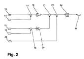
- Figure 2 shows the schematic structure of a circuit for carrying out a method according to the invention.
- a device 13 for detecting the load of the internal combustion engine 1 a device 14 for determining the nominal load of the internal combustion engine 1
- a device 15 for detecting the rotational speed of the electric motor 7 a device 16 for specifying the rotational speed of the electric motor 7 are provided.
- the device 13 for detecting the load of the internal combustion engine 1 is integrated in the present embodiment in the controller 11 of the internal combustion engine 1 and essentially comprises a sensor for detecting the engine speed and means for detecting the amount of injected fuel.
- the device 15 for detecting the rotational speed of the electric motor 7 is in the present embodiment, a self-built in the electric motor 7 sensor, but if the translation between the electric motor 7 and drive wheel is known to be a vehicle speed sensor.
- the device 16 for specifying the rotational speed of the electric motor 7 is integrated in the controller 9 of the electric motor 7.
- An attached to an accelerator pedal signal generator gives the accelerator pedal position to the control unit 10, which predetermines the accelerator pedal position a certain desired speed and thus with known translation between the electric motor 7 and the drive wheel and a target speed of the electric motor 7 necessary to achieve the target speed.
- the target load of the internal combustion engine 1 results from the power requirements by the generator 2 and the hydraulic pump 3, which are set in relation to the maximum power of the internal combustion engine 1 at a given speed.
- a first subtraction device 17 the target load determined by the device 14 for determining the nominal load of the internal combustion engine 1 is subtracted from the actual load determined by the device 13 for detecting the load on the internal combustion engine 1, and the value obtained in this comparison is then transmitted to a first multiplication device 18 which multiplies this by an adaptation factor K1 and thus determines a first controlled variable V.
- the adaptation factor K1 is predetermined and was determined empirically for the respective drive unit.
- the actual rotational speed detected by the rotational speed sensing device 15 of the electric motor 7 is compared with the target rotational speed and the obtained value is transmitted to a second multiplication device 20 where it is multiplied by a further adaptation factor K2, thus a second one To calculate controlled variable E.
- the controlled variables E and V are transmitted to a subtraction device 21, where they are subtracted from one another and thus a combined controlled variable X is determined which characterizes the deviation of the drive device from the desired state.
- an input value for a PID controller 24 is generated in which then calculates the target speed of the engine 1 and transmitted to the controller 11 of the engine 1.
- the desired value W is usually equal to zero, since in an ideally set drive, both the desired load and the actual load of the internal combustion engine 1 as well as the setpoint rotational speed and the actual rotational speed of the electric motor 7 always coincide.
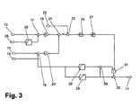
- FIG. A development of the invention is shown in FIG. There are provided a device 13 for detecting the load of the internal combustion engine 1, a device 25 for determining the actual speed of the internal combustion engine 1, a device 15 for detecting the rotational speed of the electric motor 7 and a device 16 for specifying the rotational speed of the electric motor 7.
- the target load of the internal combustion engine 1 is determined in a computing device 26 by means of a characteristic stored in the controller 11 of the internal combustion engine 1 from the actual rotational speed of the internal combustion engine 1. The calculation is done by taking at given speed, the one at this speed specifies maximum possible power of the internal combustion engine 1, based on the stored in the engine control 11 of the engine 1 map of that operating state is determined at which this power can be provided with minimal consumption.
- the load determined for this operating state is used as a target load for the further procedure.
- other calculation methods for the target load of the internal combustion engine 1 are conceivable, in which the actual speed of the internal combustion engine 1 is included, so for example, instead of a consumption-optimized torque-optimized adjustment of the target load.
- a first subtraction device 17 the determined load of the internal combustion engine 1 is subtracted from the nominal load, the value obtained is weighted by means of a first multiplication device 18 with an adaptation factor K1 and thus the parameter V is generated.
- the setpoint and actual rotational speeds of the electric traction motor 7 are also processed in a second subtraction device 19 and a second multiplication device 20 to form a parameter E.
- the characteristics E and V are combined in a subtraction device 21 to the combined controlled variable X and then compared in a third subtraction device 23 with the stored in the storage device 22 setpoint W.
- the value obtained is fed as input value into a PID controller 24 in which a dimensionless setpoint value L for the load is generated and set in a limiter 27 when an upper or lower limit value is exceeded on this limit value.
- a dimensionless setpoint value L for the load is generated and set in a limiter 27 when an upper or lower limit value is exceeded on this limit value.
- 0 or 1 is defined as the upper or lower limit value, but use cases with other limit values are also conceivable.
- a lower limit for the setpoint speed of the internal combustion engine 1 is determined in a first calculation device 28 on the basis of a characteristic stored there, and in a second calculation device 29 on the basis of a further characteristic curve.
- the lower limit value is subtracted from the upper limit value and the difference in a multiplier device 31 is multiplied by the value L.
- the value thus calculated is added to the lower limit value and the setpoint speed of the internal combustion engine 1 is calculated and transmitted to the controller 11 of the internal combustion engine 1.
- the apparatus described in FIG. 3 and the method implemented therewith have a number of advantages over the simple embodiment, which has been shown schematically in FIG.
- the specification of limit values for the setpoint speed of the internal combustion engine within limit values determined on the basis of the speed of the traction motor makes it possible, for example, to pre-adjust the rotational speed at the typically increasing power requirement at higher driving speeds.
- the individual components which serve to determine and / or evaluate the parameters for the electric motor 7 and the internal combustion engine 1 can either be provided as discrete components or integrated in an independent assembly.
- a distribution of these components to the controller 9 of the electric motor 7, the controller 11 of the internal combustion engine 1 or the control unit 10 is conceivable.
- the determination of the load of the internal combustion engine 1 can take place not only via the rotational speed of the internal combustion engine 1 and the injection quantity depending on the design of the internal combustion engine 1 and the controller 11 but also on other parameters, in particular by the power values of the consumer are detected and summed up in suitable devices.
- the electric drive element is not designed as a drive motor but for example as a drive for other units or functions of the truck or as a servomotor.
- Other electrical consumers can also be included in the system and the power required by you can be taken into account.
- the use is in one Vehicle with a hybrid drive conceivable in which, for example, in the circuit 5, a battery or a capacitor is provided to mitigate, for example, power peaks or to allow purely electrical operation in buildings.
Landscapes
- Engineering & Computer Science (AREA)
- Chemical & Material Sciences (AREA)
- Combustion & Propulsion (AREA)
- Mechanical Engineering (AREA)
- Transportation (AREA)
- Automation & Control Theory (AREA)
- Power Engineering (AREA)
- General Engineering & Computer Science (AREA)
- Control Of Vehicle Engines Or Engines For Specific Uses (AREA)
- Hybrid Electric Vehicles (AREA)
- Auxiliary Drives, Propulsion Controls, And Safety Devices (AREA)
Abstract
Description
- Die Erfindung betrifft ein Flurförderzeug mit mindestens einem Verbrennungsmotor, mindestens einer Vorrichtung zur Steuerung des Verbrennungsmotors, mindestens einem von dem Verbrennungsmotor angetriebenen Generator, mindestens einem elektrischen Antriebselement sowie mindestens einer Vorrichtung zur Steuerung des elektrischen Antriebselements. Die Erfindung betrifft ebenso ein Verfahren zum Betrieb eines derartigen Flurförderzeugs.
- Für Flurförderzeuge ist eine Vielzahl verschiedener Antriebskonzepte bekannt. Weit verbreitet sind batteriebetriebene Fahrzeuge mit elektrischem Fahrantrieb sowie Fahrzeuge mit Verbrennungsmotor und hydrodynamischer, hydrostatischer oder elektrischer Kraftübertragung.
- Elektromotorische Antriebe sind kostengünstig, als Drehstrom-Asynchronmotoren praktisch wartungsfrei und bieten insbesondere beim Einsatz als Fahrmotor große Vorteile bei der Regelung der Fahrgeschwindigkeit. Bei Flurförderzeugen ist dabei die so genannte geschwindigkeitsgeregelte Steuerung üblich, da dort, im Gegensatz beispielsweise zu Straßenkraftfahrzeugen, bei denen üblicherweise eine Leistungssteuerung des Antriebsmotors vorliegt, oder bei Baumaschinen, die häufig drehmomentgeregelt sind, zum präzisen Positionieren des Fahrzeugs, insbesondere auch an Steigungen, das genaue Einhalten der Fahrgeschwindigkeit oberste Priorität besitzt. Bei dieser Regelungsart wird üblicherweise aus der Differenz von Solldrehzahl und Istdrehzahl des elektrischen Fahrantriebsmotors das Drehmoment bestimmt, das zur Minimierung der Drehzahldifferenz nötig ist.
- Aufgrund der guten Regeleigenschaften von Elektromotoren sowie der Möglichkeit, Bauteile batteriebetriebener Fahrzeuge zu verwenden, wird auch bei Flurförderzeugen mit Verbrennungsmotor häufig ein elektrischer Fahrantrieb verwendet. Dabei wird dann die Drehzahl des Verbrennungsmotors, beispielsweise anhand der Stellung des Fahrpedals, so eingestellt, dass der Verbrennungsmotor in jedem Fall genügend Leistung liefert, um die durch die Pedalstellung vorgegebene Fahrgeschwindigkeit mit der gewünschten Beschleunigung zu erreichen und danach auch zu halten. Gegenüber batteriebetriebenen Fahrzeugen ist dabei jedoch der hohe Geräuschpegel, insbesondere bei hohen Drehzahlen des Verbrennungsmotors, nachteilig. Hohe Drehzahlen sind zudem mit hohem Kraftstoffverbrauch und Abgasemissionen verbunden und führen zu erhöhtem Verschleiß des Verbrennungsmotors.
- Der Erfindung liegt daher die Aufgabe zugrunde, ein Flurförderzeug mit mindestens einem Verbrennungsmotor, mindestens einer Vorrichtung zur Steuerung des Verbrennungsmotors, mindestens einem von dem Verbrennungsmotor angetriebenen Generator, mindestens einem elektrischen Antriebselement sowie mindestens einer Vorrichtung zur Steuerung des elektrischen Antriebselements sowie ein Verfahren zum Betrieb eines derartigen Fahrzeugs zu schaffen, bei dem unnötig hohe Drehzahlen des Verbrennungsmotors zuverlässig vermieden werden.
- Diese Aufgabe wird bezüglich des Flurförderzeugs erfindungsgemäß dadurch gelöst, dass mindestens eine Vorrichtung zur Erfassung der Belastung des Verbrennungsmotors vorgesehen ist. Indem die Belastung des Verbrennungsmotors erfasst wird, ist ersichtlich, ob die bei der augenblicklichen Drehzahl abgenommene Leistung der bei dieser Drehzahl maximal möglichen Leistung entspricht. Diese Information kann als Grundlage von Maßnahmen zur Optimierung des Betriebs, insbesondere von Verbrauch, Geräuschpegel oder Verschleiß verwendet werden. Beispielsweise wird ersichtlich ob der Verbrennungsmotor bei der augenblicklichen Drehzahl ausgelastet ist, zusätzliche Leistung abgenommen werden kann oder die Möglichkeit zur Drehzahlreduzierung besteht, d.h. die Drehzahl des Motors soweit abgesenkt werden kann, dass die entnommene Leistung annähernd der bei der gewählten Drehzahl maximal entnehmbaren Leistung entspricht. Diese Information kann sowohl an eine Bedienperson weitergegeben als auch zur automatischen Optimierung des Betriebs verwendet werden.
- Zweckmäßigerweise sind Mittel zum Vergleich von erfasster Belastung des Verbrennungsmotors und Solllast des Verbrennungsmotors vorgesehen. Die Solllast ist dabei die Belastung des Verbrennungsmotors bei gegebener Drehzahl, die sich ergibt, wenn der Verbrennungsmotor die augenblicklich zum Betrieb des Fahrzeugs erforderliche Leistung erbringt. Durch Vergleich von Solllast und tatsächlicher Belastung kann ermittelt werden, ob die vom Verbrennungsmotor verlangte Leistung erbracht werden kann, ob der Verbrennungsmotor eine für die geforderte Leistung zu hohe Drehzahl aufweist oder ob sich verlangte und gelieferte Leistung decken. Ausgehend von dieser Information kann die Drehzahl des Verbrennungsmotors für die zu erbringende Leistung optimal eingestellt werden.
- Es ist zweckmäßig, wenn die Mittel zur Erfassung der Last des Verbrennungsmotors mindestens ein Mittel zur Erfassung der Motordrehzahl und/oder des Motordrehmoments umfassen. Diese Kenngrößen können beispielsweise über Sensoren leicht ermittelt werden und werden häufig für Funktionen eines Motorsteuergeräts benötigt, weshalb ihre Ermittlung bei Verbrennungsmotoren nach dem Stand der Technik häufig ohnehin vorgesehen ist.
- Es ist zweckmäßig, wenn das elektrische Antriebselement als Elektromotor, vorzugsweise als Drehstrom-Asynchronmotor, ausgebildet ist. Elektromotoren, insbesondere Drehstrom-Asynchronmotoren, sind einfach in Herstellung und Wartung und weisen ein niedriges Geräuschniveau sowie ein gutes Regelverhalten auf.
- Weiterhin ist es von Vorteil, wenn die Mittel zur Erfassung der Belastung des Verbrennungsmotors mindestens ein Mittel zur Erfassung von Leistungsdaten des elektrischen Antriebselements, vorzugsweise zur Erfassung von Kenngrößen eines Elektromotors, umfassen. Indem die Leistungsdaten des elektrischen Antriebselements als wesentlichem Empfänger der vom Verbrennungsmotor gelieferten Leistung bekannt sind, kann daraus die Belastung des Verbrennungsmotors ermittelt werden. Kenngrößen für die Leistung können beispielsweise bei Drehstrom-Asynchronmotoren das im Umrichter bestimmte Motordrehmoment und die Motordrehzahl sein, ebenso aber auch zur Bestimmung dieser Kenngrößen geeignete andere Parameter nach dem Stand der Technik.
- Es ist ebenfalls zweckmäßig, wenn der Elektromotor Bestandteil eines Fahrantriebs ist. Bei einem Fahrantrieb eines Flurförderzeugs kommen die Vorteile eines Elektromotors besonders gut zum Tragen.
- Es ist vorteilhaft, wenn mindestens eine Vorrichtung zur Erfassung der Drehzahl des Fahrantriebs vorgesehen ist. Dadurch kann die Fahrgeschwindigkeit des Fahrzeugs überwacht werden
- Vorteilhafterweise ist die Vorrichtung zur Erfassung der Drehzahl des Fahrantriebs als Vorrichtung zur Erfassung der Drehzahl des Elektromotors ausgebildet. Vorrichtungen zur Erfassung der Drehzahl des Elektromotors sind häufig bereits vorgesehen, da die Drehzahl der Steuerung des Elektromotors als wichtige Eingangsgröße dient. Der Zusammenhang zwischen Drehzahl des Fahrantriebs und Drehzahl des Elektromotors ist vorgegeben und bei Verwendung keiner oder einer starren Übersetzung auch im Betrieb nicht veränderlich.
- Es ist weiterhin vorteilhaft, wenn Mittel zum Vergleich von erfasster und benötigter Drehzahl des Fahrantriebs vorgesehen sind. Damit kann gegebenenfalls eine Differenz zwischen gewünschter und tatsächlicher Geschwindigkeit ermittelt werden. Dies ermöglicht die Bestimmung der benötigten Leistung und damit der benötigten Drehzahl des Verbrennungsmotors, um die gewünschte Fahrgeschwindigkeit zu erreichen.
- Zweckmäßigerweise sind Mittel zur Berechnung der Solldrehzahl des Verbrennungsmotors aus der erfassten Last und der Solllast des Verbrennungsmotors sowie der tatsächlichen und der benötigten Drehzahl des Fahrantriebs vorgesehen. Dadurch kann die Regelreserve und die Dynamik des Verbrennungsmotors verbessert werden.
- Indem Mittel zur Festlegung von Grenzwerten für die Solldrehzahl des Verbrennungsmotors in Abhängigkeit von der tatsächlichen und/oder der benötigten Drehzahl des Fahrantriebs vorgesehen sind, kann die Lastanpassung des Verbrennungsmotors optimiert werden, beispielsweise indem bei höheren Fahrgeschwindigkeiten, die typischerweise einen höheren Leistungsbedarf erwarten lassen, eine Voranpassung an diesen Leistungsbedarf vorgenommen wird.
- Bezüglich des Verfahrens wird die Aufgabe erfindungsgemäß dadurch gelöst, dass die Istlast des Verbrennungsmotors ermittelt, mit der Solllast verglichen und eine Kenngröße V für die Abweichung berechnet wird. Die Vergleichsgröße für die Abweichung von Solllast und tatsächlicher Belastung dient als Regelgröße, nach der die tatsächlich erbrachte Last an die zu erbringende Solllast angepasst werden kann. Ausgehend von dieser Größe kann die Drehzahl des Verbrennungsmotors für die zu erbringende Leistung optimal eingestellt werden.
- Es ist besonders vorteilhaft, wenn die Drehzahl des Fahrantriebsmotors ermittelt, mit der von der Steuerung des Fahrantriebsmotors vorgegebenen Drehzahl verglichen und eine Kenngröße E für die Abweichung berechnet wird. Die Vergleichsgröße E für die am Fahrantrieb gewünschte und die gelieferte Leistung gibt ein Maß für die benötigte Leistung und dient damit als Regelgröße für die Solllast des Verbrennungsmotors.
- Es ist ebenfalls vorteilhaft, wenn aus der Kenngröße V und der Kenngröße E eine einzige Kenngröße X berechnet wird. Dadurch wird der Zustand des Antriebssystems in einer einzigen Kenngröße wiedergegeben, was die Regelung des Systems erleichtert.
- In einer zweckmäßigen Weiterbildung der Erfindung wird die Kenngröße X gebildet, indem die Kenngröße V und die Kenngröße E jeweils mit einem geeigneten Gewichtungsfaktor multipliziert und anschließend die Differenz der so entstandenen Größen berechnet wird. Die Gewichtungsfaktoren ermöglichen eine optimale Anpassung an die Gegebenheiten des Antriebs, insbesondere an die unterschiedliche Charakteristik von Elektromotor und Verbrennungsmotor.
- Weiterhin ist es vorteilhaft, wenn die aus den Kenngrößen V und E gebildete Kenngröße X als Regelgröße für die Drehzahl des Verbrennungsmotors, insbesondere bei einer Berechung nach dem PID-Algorithmus, verwendet wird. Die Kenngröße X ist besonders gut geeignet, um die Drehzahl des Verbrennungsmotors zu regeln, da diese den Zustand des Antriebssystems sehr gut wiedergibt.
- Es ist ebenfalls vorteilhaft, wenn anhand der tatsächlichen und/oder der benötigten Drehzahl des Fahrantriebs mindestens ein oberer Grenzwert sowie mindestens ein unterer Grenzwert für die Solldrehzahl des Verbrennungsmotors festgelegt werden. Dadurch kann die Lastanpassung des Verbrennungsmotors bei wechselnden Bedingungen optimiert werden, beispielsweise indem bei höheren Fahrgeschwindigkeiten, die typischerweise einen höheren Leistungsbedarf erwarten lassen, eine Voranpassung an diesen Leistungsbedarf vorgenommen wird.
- Weitere Vorteile und Einzelheiten der Erfindung werden im Folgenden anhand des in der Zeichnung dargestellten Ausführungsbeispiels näher erläutert. Gleiche beziehungsweise funktional gleiche Teile sind mit gleichen Bezugszeichen gekennzeichnet. Dabei zeigt
- Figur 1
- den schematischen Aufbau eines erfindungsgemäßen Flurförderzeugs,
- Figur 2
- den schematischen Aufbau einer Schaltung zur Durchführung des erfindungsgemäßen Verfahrens (Bild 3),
- Figur 3
- den schematischen Aufbau einer weiteren Schaltung zur Durchführung des erfindungsgemäßen Verfahrens.
- In Figur 1 ist schematisch der Aufbau eines erfindungsgemäßen Flurförderzeugs gezeigt. Auf die Darstellung von Aggregaten und Komponenten, wie beispielsweise Teile der hydraulischen oder elektrischen Anlage, die zum Verständnis der Erfindung nicht erforderlich sind, wurde weitgehend verzichtet. Ein Verbrennungsmotor 1 treibt einen Generator 2 sowie eine Hydraulikpumpe 3 an. Die Hydraulikpumpe 3 ist mit einem hier nicht dargestellten Hydraulikkreis verbunden, der beispielsweise Hub- und/oder Neigezylinder für einen Hubmast umfassen kann. Der Generator 2 ist im vorliegenden Ausführungsbeispiel als dreiphasiger Synchrongenerator ausgeführt und steht mit einem Gleichrichter 4 in Verbindung. Über einen Gleichstrom- bzw. Gleichspannungszwischenkreis 5 ist ein Fahrumrichter 6 angeschlossen, der wiederum einen als Drehstrom-Asynchronmotor ausgebildeten Fahrmotor 7 mit Strom versorgt. Der Fahrmotor 7 bildet mit einer Antriebsachse 8a den Fahrantrieb 8 des Flurförderzeugs. Im Fahrumrichter 6 integriert ist eine elektrische Steuerung 9, die die Drehzahl des Fahrmotors 7 entsprechend der Geschwindigkeitsvorgaben einer Steuereinheit 10 regelt. Die Steuereinheit 10 steht mit der Steuerung 11 des Verbrennungsmotors 1, dem Gleichrichter 4 sowie dem Umrichter 6 über Datenleitungen 12 in Verbindung, wobei der Datenaustausch beispielsweise nach dem CAN-Bus-Standard erfolgen kann.
- Die Steuereinheit 10 erhält über hier nicht dargestellte Bedienelemente, wie beispielsweise ein Fahr- und/oder Bremspedal Vorgaben für die Fahrgeschwindigkeit des Fahrzeugs. Es ist bei Flurförderzeugen üblich, die so genannte geschwindigkeitsgeregelte Steuerung zu verwenden, da zum präzisen Positionieren des Fahrzeugs, insbesondere auch an Steigungen, das genaue Einhalten der Fahrgeschwindigkeit oberste Priorität besitzt. Bei dieser Regelungsart wird üblicherweise aus der Differenz von Solldrehzahl und Istdrehzahl des elektrischen Fahrantriebsmotors 7 das Drehmoment bestimmt, das zur Minimierung der Drehzahldifferenz nötig ist. Zusätzlich erhält die Steuereinheit 10 Informationen über den Leistungsbedarf des Hydraulikkreises, der vorrangig vor dem Fahrantrieb 8 gedeckt wird. Die Steuereinheit 10 enthält im gezeigten Ausführungsbeispiel auch die wesentlichen Vorrichtungen zur Realisierung der Erfindung.
- Figur 2 zeigt den schematischen Aufbau einer Schaltung zur Durchführung eines erfindungsgemäßen Verfahrens. Es sind eine erfindungsgemäße Vorrichtung 13 zur Erfassung der Belastung des Verbrennungsmotors 1, eine Vorrichtung 14 zur Ermittlung der Solllast des Verbrennungsmotors 1, eine Vorrichtung 15 zur Erfassung der Drehzahl des Elektromotors 7 sowie eine Vorrichtung 16 zur Vorgabe der Drehzahl des Elektromotors 7 vorgesehen.
- Die Vorrichtung 13 zur Erfassung der Belastung des Verbrennungsmotors 1 ist im vorliegenden Ausführungsbeispiel in die Steuerung 11 des Verbrennungsmotors 1 integriert und umfasst im Wesentlichen einen Sensor zur Erfassung der Motordrehzahl sowie Mittel zur Erfassung der Menge des eingespritzten Kraftstoffs.
- Die Vorrichtung 15 zur Erfassung der Drehzahl des Elektromotors 7 ist im vorliegenden Ausführungsbeispiel ein im Elektromotor 7 selbst verbauter Sensor, kann aber, wenn die Übersetzung zwischen Elektromotor 7 und Antriebsrad bekannt ist, ein Fahrgeschwindigkeitssensor sein.
- Die Vorrichtung 16 zur Vorgabe der Drehzahl des Elektromotors 7 ist in der Steuerung 9 des Elektromotors 7 integriert. Ein an einem Fahrpedal angebrachter Signalgeber gibt die Fahrpedalstellung an die Steuereinheit 10 weiter, wobei diese der Fahrpedalstellung eine bestimmte Wunschgeschwindigkeit und damit bei bekannter Übersetzung zwischen Elektromotor 7 und Antriebsrad auch eine Solldrehzahl des Elektromotors 7 und die zur Erreichung der Solldrehzahl notwendige Leistung vorgibt.
- Die Solllast des Verbrennungsmotors 1 ergibt sich aus den Leistungsanforderungen durch den Generator 2 sowie die Hydraulikpumpe 3, die in Relation zur bei gegebener Drehzahl maximalen Leistung des Verbrennungsmotors 1 gesetzt werden.
- In einer ersten Subtraktionsvorrichtung 17 wird die von der Vorrichtung 14 zur Ermittlung der Solllast des Verbrennungsmotors 1 ermittelte Solllast von der mittels der Vorrichtung 13 zur Erfassung der Belastung des Verbrennungsmotors 1 ermittelten Istlast subtrahiert und der in diesem Vergleich erhaltene Wert anschließend an eine erste Multiplikationsvorrichtung 18 übermittelt, die diesen mit einem Anpassungsfaktor K1 multipliziert und so eine erste Regelgröße V ermittelt. Der Anpassungsfaktor K1 ist vorgegeben und wurde empirisch für die jeweilige Antriebseinheit ermittelt. In einer zweiten Subtraktionsvorrichtung 19 wird die von der Vorrichtung 15 zur Erfassung der Drehzahl des Elektromotors 7 erfasste tatsächliche Drehzahl mit der Solldrehzahl verglichen und der erhaltene Wert an eine zweite Multiplikationsvorrichtung 20 übermittelt, wo er mit einem weiteren Anpassungsfaktor K2 multipliziert wird, um so eine zweite Regelgröße E zu berechnen.
- Die Regelgrößen E und V werden an eine Subtraktionsvorrichtung 21 übermittelt, dort voneinander subtrahiert und so eine kombinierte Regelgröße X ermittelt, die die Abweichung der Antriebseinrichtung vom Sollzustand charakterisiert.
- Durch Vergleich der Kenngröße X mit einem in einer Speichervorrichtung 22 vorgehaltenen Sollwert W in einer vierten Subtraktionsvorrichtung 23 wird ein Eingangswert für einen PID-Regler 24 erzeugt, in dem danach die Solldrehzahl des Verbrennungsmotors 1 berechnet und an die Steuerung 11 des Verbrennungsmotors 1 übermittelt wird. Der Sollwert W ist üblicherweise gleich Null, da bei einem ideal eingestellten Antrieb sowohl Solllast und tatsächliche Last des Verbrennungsmotors 1 als auch Solldrehzahl und tatsächliche Drehzahl des Elektromotors 7 jeweils übereinstimmen.
- Eine Weiterbildung der Erfindung ist in Figur 3 gezeigt. Es sind eine erfindungsgemäße Vorrichtung 13 zur Erfassung der Belastung des Verbrennungsmotors 1, eine Vorrichtung 25 zur Ermittlung der Istdrehzahl des Verbrennungsmotors 1, eine Vorrichtung 15 zur Erfassung der Drehzahl des Elektromotors 7 sowie eine Vorrichtung 16 zur Vorgabe der Drehzahl des Elektromotors 7 vorgesehen. Bei dieser Ausbildung der Erfindung wird die Solllast des Verbrennungsmotors 1 in einer Berechnungsvorrichtung 26 mittels einer in der Steuerung 11 des Verbrennungsmotors 1 abgelegten Kennlinie aus der Ist-Drehzahl des Verbrennungsmotors 1 ermittelt. Die Berechnung erfolgt, indem bei gegebener Drehzahl, die eine bei dieser Drehzahl maximal mögliche Leistung des Verbrennungsmotors 1 vorgibt, anhand des in der Motorsteuerung 11 des Verbrennungsmotors 1 abgelegten Kennfeldes derjenige Betriebszustand ermittelt wird, bei dem diese Leistung mit minimalem Verbrauch erbracht werden kann. Die für diesen Betriebszustand ermittelte Last wird als Solllast für das weitere Verfahren verwendet. Es sind jedoch auch andere Berechnungsmethoden für die Solllast des Verbrennungsmotors 1 denkbar, in die die Istdrehzahl des Verbrennungsmotors 1 einbezogen wird, so kann beispielsweise insbesondere anstelle einer verbrauchsoptimierten eine drehmomentoptimierte Einstellung der Solllast erfolgen.
- In einer ersten Subtraktionsvorrichtung 17 wird die ermittelte Last des Verbrennungsmotors 1 von der Solllast abgezogen, der erhaltene Wert mittels einer ersten Multiplikationsvorrichtung 18 mit einem Anpassungsfaktor K1 gewichtet und so die Kenngröße V generiert. Ebenso wie im vorhergehenden Ausführungsbeispiel werden auch Soll- und Istdrehzahl des elektrischen Fahrmotors 7 in einer zweiten Subtraktionsvorrichtung 19 sowie einer zweiten Multiplikationsvorrichtung 20 zu einer Kenngröße E aufbereitet. Die Kenngrößen E und V werden in einer Subtraktionsvorrichtung 21 zu der kombinierten Regelgröße X kombiniert und dann in einer dritten Subtraktionsvorrichtung 23 mit dem in der Speichervorrichtung 22 vorgehaltenen Sollwert W vergleichen. Der erhaltene Wert wird als Eingangswert in einen PID-Regler 24 gespeist, in dem ein dimensionsloser Sollwert L für die Last generiert und in einem Begrenzer 27 bei Überschreiten eines oberen oder unteren Grenzwertes auf diesen Grenzwert gesetzt wird. Im vorliegenden Ausführungsbeispiel ist als oberer beziehungsweise unterer Grenzwert 0 beziehungsweise 1 definiert, es sind jedoch auch Anwendungsfälle mit anderen Grenzwerten denkbar.
- Aus der Solldrehzahl des Elektromotors 7 wird in einer ersten Berechnungsvorrichtung 28 anhand einer dort abgelegten Kennlinie eine Obergrenze und in einer zweiten Berechnungsvorrichtung 29 anhand einer weiteren Kennlinie eine Untergrenze für die Solldrehzahl des Verbrennungsmotors 1 ermittelt. In einer weiteren Subtraktionsvorrichtung 30 wird der untere Grenzwert vom oberen Grenzwert abgezogen und die Differenz in einer Multiplikationsvorrichtung 31 mit dem Wert L multipliziert. In einer Additionsvorrichtung 32 wird der so berechnete Wert zu dem unteren Grenzwert addiert und so die Solldrehzahl des Verbrennungsmotors 1 berechnet und an die Steuerung 11 des Verbrennungsmotors 1 übermittelt.
- Die in Figur 3 beschriebene Vorrichtung und das damit durchgeführte Verfahren weisen gegenüber der einfachen Ausführungsform, die in Figur 2 schematisch dargestellt wurde, eine Reihe von Vorteilen auf. Indem die Solllast des Verbrennungsmotors 1 mithilfe der ermittelten Drehzahl des Verbrennungsmotors 1 vorgegeben wird, ist es möglich, bei geringen Drehzahlen eine kleinere Solllast vorzugeben und damit eine höhere Regelreserve und Dynamik des Verbrennungsmotors 1 zu erreichen. Die Vorgabe von Grenzwerten für die Solldrehzahl des Verbrennungsmotors innerhalb von anhand der Drehzahl des Fahrmotors ermittelten Grenzwerten ermöglicht es beispielsweise, eine Voranpassung der Drehzahl an den bei höheren Fahrgeschwindigkeiten typischerweise steigenden Leistungsbedarf vorzunehmen.
- Im Ausführungsbeispiel wurde die Erfindung für den Fall der Vorwärtsfahrt des Flurförderzeugs erläutert. Bei Rückwärtsfahrt wird die negative Solldrehzahl des Fahrantriebsmotors 7 durch eine Vorzeichenanpassung berücksichtigt.
- Selbstverständlich sind auch andere Ausführungsformen der Erfindung denkbar. So können beispielsweise die einzelnen Komponenten, die zur Ermittlung und/oder Auswertung der Kenngrößen für Elektromotor 7 und Verbrennungsmotor 1 dienen, entweder als diskrete Bausteine vorgesehen oder in einer eigenständigen Baugruppe integriert sein. Auch eine Verteilung diese Komponenten auf die Steuerung 9 des Elektromotors 7, die Steuerung 11 des Verbrennungsmotors 1 oder die Steuerungseinheit 10 ist denkbar. Die Ermittlung der Belastung des Verbrennungsmotors 1 kann außer über die Drehzahl des Verbrennungsmotors 1 und die Einspritzmenge je nach Bauweise des Verbrennungsmotors 1 und der Steuerung 11 auch über andere Kenngrößen erfolgen, insbesondere auch, indem die Leistungswerte der Verbraucher in geeigneten Vorrichtungen erfasst und aufsummiert werden.
- Selbstverständlich sind auch Ausführungsformen denkbar, bei denen das elektrische Antriebselement nicht als Fahrmotor sondern beispielsweise als Antrieb für andere Aggregate oder Funktionen des Flurförderzeugs oder als Stellmotor ausgebildet ist. Auch weitere elektrische Verbraucher könne in das System einbezogen und die von Ihnen geforderte Leistung berücksichtigt werden. Ebenso ist die Verwendung in einem Fahrzeug mit einem Hybridantrieb denkbar, bei dem beispielsweise im Stromkreis 5 noch eine Batterie oder ein Kondensator vorgesehen ist, um beispielsweise Leistungsspitzen abzumildern oder rein elektrischen Betrieb in Gebäuden zu ermöglichen.
Claims (17)
- Flurförderzeug mit mindestens einem Verbrennungsmotor (1), mindestens einer Vorrichtung (11) zur Steuerung des Verbrennungsmotors, mindestens einem von dem Verbrennungsmotor (1) angetriebenen Generator (2), mindestens einem elektrischen Antriebselement (7) sowie mindestens einer Vorrichtung (9) zur Steuerung des elektrischen Antriebselements, dadurch gekennzeichnet, dass mindestens eine Vorrichtung (13) zur Erfassung der Belastung des Verbrennungsmotors (1) vorgesehen ist.
- Flurförderzeug nach Anspruch 1, dadurch gekennzeichnet, dass Mittel (17) zum Vergleich der erfassten Belastung des Verbrennungsmotors (1) und der Solllast des Verbrennungsmotors (1) vorgesehen sind.
- Flurförderzeug nach Anspruch 1 oder 2, dadurch gekennzeichnet, dass die Mittel (13) zur Erfassung der Belastung des Verbrennungsmotors (1) mindestens ein Mittel zur Erfassung der Motordrehzahl und/oder des Motordrehmoments umfassen.
- Flurförderzeug nach einem der Ansprüche 1 bis 3, dadurch gekennzeichnet, dass das elektrische Antriebselement (7) als Elektromotor, vorzugsweise als Drehstrom-Asynchronmotor (7) ausgebildet ist.
- Flurförderzeug nach einem der Ansprüche 1 bis 4, dadurch gekennzeichnet, dass die Mittel (13) zur Erfassung der Belastung des Verbrennungsmotors (1) mindestens ein Mittel zur Erfassung von Leistungsdaten des elektrischen Antriebselements, vorzugsweise zur Erfassung von Kenngrößen eines Elektromotors (7), umfassen.
- Flurförderzeug nach einem der Ansprüche 1 bis 5, dadurch gekennzeichnet, dass der Elektromotor (7) Bestandteil eines Fahrantriebs (8) ist.
- Flurförderzeug nach einem der Ansprüche 1 bis 6, dadurch gekennzeichnet, dass mindestens eine Vorrichtung (15) zur Erfassung der Drehzahl des Fahrantriebs (8) vorgesehen ist.
- Flurförderzeug nach einem der Ansprüche 1 bis 7, dadurch gekennzeichnet, dass die Vorrichtung (15) zur Erfassung der Drehzahl des Fahrantriebs (8) als Vorrichtung (15) zur Erfassung der Drehzahl des Elektromotors (7) ausgebildet ist.
- Flurförderzeug nach einem der Ansprüche 1 bis 8, dadurch gekennzeichnet, dass Mittel (19) zum Vergleich von erfasster und benötigter Drehzahl des Fahrantriebs (8) vorgesehen sind.
- Flurförderzeug nach einem der Ansprüche 1 bis 9, dadurch gekennzeichnet, dass Mittel (24) zur Berechnung der Solldrehzahl des Verbrennungsmotors (1) aus der erfassten Last und der Solllast des Verbrennungsmotors (1) sowie der tatsächlichen und der benötigten Drehzahl des Fahrantriebs (8) vorgesehen sind.
- Flurförderzeug nach einem der Ansprüche 1 bis 10, dadurch gekennzeichnet, dass Mittel zur Festlegung von Grenzwerten für die Solldrehzahl des Verbrennungsmotors in Abhängigkeit von der tatsächlichen und/oder der benötigten Drehzahl des Fahrantriebs (8) vorgesehen sind
- Verfahren zum Betrieb eines Flurförderzeugs nach einem der vorhergehenden Ansprüche, dadurch gekennzeichnet, dass die Istlast des Verbrennungsmotors (1) ermittelt, mit der Solllast verglichen und eine Kenngröße V für die Abweichung berechnet wird.
- Verfahren nach Anspruch 12, dadurch gekennzeichnet, dass die Drehzahl des Fahrantriebsmotors (7) ermittelt, mit der von der Steuerung (9) des Fahrantriebsmotors (7) vorgegebenen Drehzahl verglichen und eine Kenngröße E für die Abweichung berechnet wird.
- Verfahren nach einem der Ansprüche 12 oder 13, dadurch gekennzeichnet, dass aus der Kenngröße V und der Kenngröße E eine einzige Kenngröße X berechnet wird.
- Verfahren nach einem der Ansprüche 12 bis 14, dadurch gekennzeichnet, dass die Kenngröße X gebildet wird, indem die Kenngröße V und die Kenngröße E jeweils mit einem geeigneten Gewichtungsfaktor multipliziert und anschließend die Differenz der so entstandenen Größen berechnet wird.
- Verfahren nach einem der Ansprüche 12 bis 15, dadurch gekennzeichnet, dass die aus den Kenngrößen V und E gebildete Kenngröße X als Regelgröße für die Drehzahl des Verbrennungsmotors (1), insbesondere bei einer Berechung nach dem PID-Algorithmus, verwendet wird.
- Verfahren nach einem der Ansprüche 12 bis 16, dadurch gekennzeichnet, dass anhand der tatsächlichen und/oder der benötigten Drehzahl des Fahrantriebs (8) mindestens ein oberer Grenzwert sowie mindestens ein unterer Grenzwert für die Solldrehzahl des Verbrennungsmotors (1) festgelegt werden.
Applications Claiming Priority (2)
| Application Number | Priority Date | Filing Date | Title |
|---|---|---|---|
| DE102006044049 | 2006-09-20 | ||
| DE102006053631A DE102006053631A1 (de) | 2006-09-20 | 2006-11-14 | Flurförderzeug mit einem Verbrennungsmotor |
Publications (3)
| Publication Number | Publication Date |
|---|---|
| EP1902921A2 true EP1902921A2 (de) | 2008-03-26 |
| EP1902921A3 EP1902921A3 (de) | 2009-07-15 |
| EP1902921B1 EP1902921B1 (de) | 2016-10-12 |
Family
ID=38830363
Family Applications (1)
| Application Number | Title | Priority Date | Filing Date |
|---|---|---|---|
| EP07016577.4A Not-in-force EP1902921B1 (de) | 2006-09-20 | 2007-08-23 | Flurförderzeug mit einem Verbrennungsmotor |
Country Status (2)
| Country | Link |
|---|---|
| EP (1) | EP1902921B1 (de) |
| DE (1) | DE102006053631A1 (de) |
Citations (3)
| Publication number | Priority date | Publication date | Assignee | Title |
|---|---|---|---|---|
| DE4321767A1 (de) | 1993-06-30 | 1995-01-12 | Linde Ag | Verfahren zum Betreiben eines Flurförderzeugs |
| US5461289A (en) | 1991-10-04 | 1995-10-24 | Mannesmann Aktiengesellschaft | Drive system for a motor vehicle |
| EP1013498A2 (de) | 1998-12-18 | 2000-06-28 | Honda Giken Kogyo Kabushiki Kaisha | Ausgangssteuersystem für ein Serienhybridfahrzeug |
Family Cites Families (5)
| Publication number | Priority date | Publication date | Assignee | Title |
|---|---|---|---|---|
| DE4205770C2 (de) * | 1992-02-21 | 1994-05-05 | Mannesmann Ag | Fahrzeug mit Verbrennungsmotor, elektrischem Generator und Elektromotor |
| US5345154A (en) * | 1993-02-26 | 1994-09-06 | General Electric Company | Electric continuously variable transmission and controls for operation of a heat engine in a closed-loop power-control mode |
| US6907325B1 (en) * | 2003-09-24 | 2005-06-14 | Ford Global Technologies, Llc | Method of operating a hybrid electric vehicle to limit noise, vibration, and harshness |
| US7350611B2 (en) * | 2004-06-15 | 2008-04-01 | Caterpillar Inc | Method for controlling an electric drive machine |
| US7472008B2 (en) * | 2004-07-23 | 2008-12-30 | Caterpillar Inc. | Systems and methods for controlling mobile machine power |
-
2006
- 2006-11-14 DE DE102006053631A patent/DE102006053631A1/de not_active Withdrawn
-
2007
- 2007-08-23 EP EP07016577.4A patent/EP1902921B1/de not_active Not-in-force
Patent Citations (3)
| Publication number | Priority date | Publication date | Assignee | Title |
|---|---|---|---|---|
| US5461289A (en) | 1991-10-04 | 1995-10-24 | Mannesmann Aktiengesellschaft | Drive system for a motor vehicle |
| DE4321767A1 (de) | 1993-06-30 | 1995-01-12 | Linde Ag | Verfahren zum Betreiben eines Flurförderzeugs |
| EP1013498A2 (de) | 1998-12-18 | 2000-06-28 | Honda Giken Kogyo Kabushiki Kaisha | Ausgangssteuersystem für ein Serienhybridfahrzeug |
Also Published As
| Publication number | Publication date |
|---|---|
| DE102006053631A1 (de) | 2008-04-03 |
| EP1902921B1 (de) | 2016-10-12 |
| EP1902921A3 (de) | 2009-07-15 |
Similar Documents
| Publication | Publication Date | Title |
|---|---|---|
| DE3619703C2 (de) | ||
| DE112007000061B4 (de) | Antriebssystem für elektrisch angetriebenes Kipperfahrzeug | |
| DE102007023743B4 (de) | Steuerungsvorrichtung für eine Brennkraftmaschine | |
| EP2443011A1 (de) | Verfahren und vorrichtung zur bestimmung des beginns einer startphase eines verbrennungsmotors in einem hybridfahrzeug | |
| DE112004001397T5 (de) | Fahrzeug und Fahrzeug-Steuerverfahren | |
| DE112011105634T5 (de) | Elektrofahrzeug | |
| DE10337002A1 (de) | Verfahren zur Steuerung der Antriebsleistungsverteilung in einem Kraftfahrzeug mit Hybridantrieb | |
| DE10310105A1 (de) | Regelungs-Algorithmus für ein Wirbelstrom-Bremssystem | |
| WO2007115922A1 (de) | Betriebsarten- und momentenkoordination bei hybrid-kraftfahrzeugantrieben | |
| WO2016055197A1 (de) | Steuervorrichtung für eine elektromaschine, fahrzeug und verfahren | |
| EP3592588B1 (de) | Verfahren zur steuerung eines kraftfahrzeuges und kraftfahrzeug | |
| DE102006001201A1 (de) | Verfahren zur Steuerung eines Batterieladungsvorgangs | |
| DE112023002570T5 (de) | Drehmomentverteilungssystem und -verfahren für Doppelantriebsachsen eines Elektrofahrzeugs | |
| WO2004106104A1 (de) | Kraftfahrzeug und elektronische steuereinrichtung dafür | |
| DE102007004171B4 (de) | Verfahren und Vorrichtung zum Einstellen einer Leerlaufdrehzahl | |
| DE10111562A1 (de) | Verfahren zum Betreiben eines lastabhängigen Stromerzeugungssystems in einem Fahrzeug | |
| DE10153585A1 (de) | Verfahren zur Regelung eines Elektro-Antriebs eines Fahrzeugs | |
| EP2818675A1 (de) | Steuerung für das Antriebssystem einer Arbeitsmaschine | |
| EP1902921B1 (de) | Flurförderzeug mit einem Verbrennungsmotor | |
| CH706518A1 (de) | Steuerung für das Antriebssystem einer Arbeitsmaschine. | |
| EP2709888A1 (de) | Verfahren zum betreiben eines antriebsstrangs eines hybridfahrzeugs | |
| DE102010053560A1 (de) | Lastabwurf eines hybriden Zubehörleistungsmoduls zum Schutz einer Hochspannungsbatterie | |
| DE102012201163B4 (de) | Stellverfahren und steuereinheit zum stellen einer ansteuerfrequenz eines komfortorientiert betreibbaren elektrischen aktuators sowie deren verwendung | |
| DE10232805B4 (de) | Startergeneratorvorrichtung und Verfahren zum Steuern einer Startergeneratorvorrichtung bei einem Kraftfahrzeug | |
| EP1537315B1 (de) | Verfahren und vorrichtung zur steuerung eines antriebsstrangs |
Legal Events
| Date | Code | Title | Description |
|---|---|---|---|
| PUAI | Public reference made under article 153(3) epc to a published international application that has entered the european phase |
Free format text: ORIGINAL CODE: 0009012 |
|
| AK | Designated contracting states |
Kind code of ref document: A2 Designated state(s): AT BE BG CH CY CZ DE DK EE ES FI FR GB GR HU IE IS IT LI LT LU LV MC MT NL PL PT RO SE SI SK TR |
|
| AX | Request for extension of the european patent |
Extension state: AL BA HR MK YU |
|
| PUAL | Search report despatched |
Free format text: ORIGINAL CODE: 0009013 |
|
| AK | Designated contracting states |
Kind code of ref document: A3 Designated state(s): AT BE BG CH CY CZ DE DK EE ES FI FR GB GR HU IE IS IT LI LT LU LV MC MT NL PL PT RO SE SI SK TR |
|
| AX | Request for extension of the european patent |
Extension state: AL BA HR MK RS |
|
| 17P | Request for examination filed |
Effective date: 20091204 |
|
| 17Q | First examination report despatched |
Effective date: 20100113 |
|
| AKX | Designation fees paid |
Designated state(s): AT BE BG CH CY CZ DE DK EE ES FI FR GB GR HU IE IS IT LI LT LU LV MC MT NL PL PT RO SE SI SK TR |
|
| GRAP | Despatch of communication of intention to grant a patent |
Free format text: ORIGINAL CODE: EPIDOSNIGR1 |
|
| INTG | Intention to grant announced |
Effective date: 20160602 |
|
| GRAS | Grant fee paid |
Free format text: ORIGINAL CODE: EPIDOSNIGR3 |
|
| GRAA | (expected) grant |
Free format text: ORIGINAL CODE: 0009210 |
|
| AK | Designated contracting states |
Kind code of ref document: B1 Designated state(s): AT BE BG CH CY CZ DE DK EE ES FI FR GB GR HU IE IS IT LI LT LU LV MC MT NL PL PT RO SE SI SK TR |
|
| REG | Reference to a national code |
Ref country code: GB Ref legal event code: FG4D Free format text: NOT ENGLISH |
|
| REG | Reference to a national code |
Ref country code: CH Ref legal event code: EP |
|
| REG | Reference to a national code |
Ref country code: AT Ref legal event code: REF Ref document number: 836210 Country of ref document: AT Kind code of ref document: T Effective date: 20161015 |
|
| REG | Reference to a national code |
Ref country code: IE Ref legal event code: FG4D Free format text: LANGUAGE OF EP DOCUMENT: GERMAN |
|
| REG | Reference to a national code |
Ref country code: DE Ref legal event code: R096 Ref document number: 502007015181 Country of ref document: DE |
|
| REG | Reference to a national code |
Ref country code: DE Ref legal event code: R082 Ref document number: 502007015181 Country of ref document: DE Representative=s name: PATENTSHIP PATENTANWALTSGESELLSCHAFT MBH, DE |
|
| REG | Reference to a national code |
Ref country code: LT Ref legal event code: MG4D |
|
| REG | Reference to a national code |
Ref country code: NL Ref legal event code: MP Effective date: 20161012 |
|
| REG | Reference to a national code |
Ref country code: DE Ref legal event code: R082 Ref document number: 502007015181 Country of ref document: DE Representative=s name: PATENTSHIP PATENTANWALTSGESELLSCHAFT MBH, DE |
|
| PG25 | Lapsed in a contracting state [announced via postgrant information from national office to epo] |
Ref country code: LV Free format text: LAPSE BECAUSE OF FAILURE TO SUBMIT A TRANSLATION OF THE DESCRIPTION OR TO PAY THE FEE WITHIN THE PRESCRIBED TIME-LIMIT Effective date: 20161012 |
|
| PG25 | Lapsed in a contracting state [announced via postgrant information from national office to epo] |
Ref country code: GR Free format text: LAPSE BECAUSE OF FAILURE TO SUBMIT A TRANSLATION OF THE DESCRIPTION OR TO PAY THE FEE WITHIN THE PRESCRIBED TIME-LIMIT Effective date: 20170113 Ref country code: SE Free format text: LAPSE BECAUSE OF FAILURE TO SUBMIT A TRANSLATION OF THE DESCRIPTION OR TO PAY THE FEE WITHIN THE PRESCRIBED TIME-LIMIT Effective date: 20161012 Ref country code: LT Free format text: LAPSE BECAUSE OF FAILURE TO SUBMIT A TRANSLATION OF THE DESCRIPTION OR TO PAY THE FEE WITHIN THE PRESCRIBED TIME-LIMIT Effective date: 20161012 |
|
| PG25 | Lapsed in a contracting state [announced via postgrant information from national office to epo] |
Ref country code: PT Free format text: LAPSE BECAUSE OF FAILURE TO SUBMIT A TRANSLATION OF THE DESCRIPTION OR TO PAY THE FEE WITHIN THE PRESCRIBED TIME-LIMIT Effective date: 20170213 Ref country code: FI Free format text: LAPSE BECAUSE OF FAILURE TO SUBMIT A TRANSLATION OF THE DESCRIPTION OR TO PAY THE FEE WITHIN THE PRESCRIBED TIME-LIMIT Effective date: 20161012 Ref country code: ES Free format text: LAPSE BECAUSE OF FAILURE TO SUBMIT A TRANSLATION OF THE DESCRIPTION OR TO PAY THE FEE WITHIN THE PRESCRIBED TIME-LIMIT Effective date: 20161012 Ref country code: NL Free format text: LAPSE BECAUSE OF FAILURE TO SUBMIT A TRANSLATION OF THE DESCRIPTION OR TO PAY THE FEE WITHIN THE PRESCRIBED TIME-LIMIT Effective date: 20161012 Ref country code: IS Free format text: LAPSE BECAUSE OF FAILURE TO SUBMIT A TRANSLATION OF THE DESCRIPTION OR TO PAY THE FEE WITHIN THE PRESCRIBED TIME-LIMIT Effective date: 20170212 Ref country code: PL Free format text: LAPSE BECAUSE OF FAILURE TO SUBMIT A TRANSLATION OF THE DESCRIPTION OR TO PAY THE FEE WITHIN THE PRESCRIBED TIME-LIMIT Effective date: 20161012 |
|
| REG | Reference to a national code |
Ref country code: DE Ref legal event code: R097 Ref document number: 502007015181 Country of ref document: DE |
|
| PG25 | Lapsed in a contracting state [announced via postgrant information from national office to epo] |
Ref country code: CZ Free format text: LAPSE BECAUSE OF FAILURE TO SUBMIT A TRANSLATION OF THE DESCRIPTION OR TO PAY THE FEE WITHIN THE PRESCRIBED TIME-LIMIT Effective date: 20161012 Ref country code: SK Free format text: LAPSE BECAUSE OF FAILURE TO SUBMIT A TRANSLATION OF THE DESCRIPTION OR TO PAY THE FEE WITHIN THE PRESCRIBED TIME-LIMIT Effective date: 20161012 Ref country code: DK Free format text: LAPSE BECAUSE OF FAILURE TO SUBMIT A TRANSLATION OF THE DESCRIPTION OR TO PAY THE FEE WITHIN THE PRESCRIBED TIME-LIMIT Effective date: 20161012 Ref country code: RO Free format text: LAPSE BECAUSE OF FAILURE TO SUBMIT A TRANSLATION OF THE DESCRIPTION OR TO PAY THE FEE WITHIN THE PRESCRIBED TIME-LIMIT Effective date: 20161012 Ref country code: EE Free format text: LAPSE BECAUSE OF FAILURE TO SUBMIT A TRANSLATION OF THE DESCRIPTION OR TO PAY THE FEE WITHIN THE PRESCRIBED TIME-LIMIT Effective date: 20161012 |
|
| PLBE | No opposition filed within time limit |
Free format text: ORIGINAL CODE: 0009261 |
|
| STAA | Information on the status of an ep patent application or granted ep patent |
Free format text: STATUS: NO OPPOSITION FILED WITHIN TIME LIMIT |
|
| PG25 | Lapsed in a contracting state [announced via postgrant information from national office to epo] |
Ref country code: IT Free format text: LAPSE BECAUSE OF FAILURE TO SUBMIT A TRANSLATION OF THE DESCRIPTION OR TO PAY THE FEE WITHIN THE PRESCRIBED TIME-LIMIT Effective date: 20161012 Ref country code: BG Free format text: LAPSE BECAUSE OF FAILURE TO SUBMIT A TRANSLATION OF THE DESCRIPTION OR TO PAY THE FEE WITHIN THE PRESCRIBED TIME-LIMIT Effective date: 20170112 |
|
| 26N | No opposition filed |
Effective date: 20170713 |
|
| PG25 | Lapsed in a contracting state [announced via postgrant information from national office to epo] |
Ref country code: SI Free format text: LAPSE BECAUSE OF FAILURE TO SUBMIT A TRANSLATION OF THE DESCRIPTION OR TO PAY THE FEE WITHIN THE PRESCRIBED TIME-LIMIT Effective date: 20161012 |
|
| REG | Reference to a national code |
Ref country code: CH Ref legal event code: PL |
|
| PG25 | Lapsed in a contracting state [announced via postgrant information from national office to epo] |
Ref country code: MC Free format text: LAPSE BECAUSE OF FAILURE TO SUBMIT A TRANSLATION OF THE DESCRIPTION OR TO PAY THE FEE WITHIN THE PRESCRIBED TIME-LIMIT Effective date: 20161012 |
|
| GBPC | Gb: european patent ceased through non-payment of renewal fee |
Effective date: 20170823 |
|
| PG25 | Lapsed in a contracting state [announced via postgrant information from national office to epo] |
Ref country code: CH Free format text: LAPSE BECAUSE OF NON-PAYMENT OF DUE FEES Effective date: 20170831 Ref country code: LI Free format text: LAPSE BECAUSE OF NON-PAYMENT OF DUE FEES Effective date: 20170831 |
|
| REG | Reference to a national code |
Ref country code: FR Ref legal event code: ST Effective date: 20180430 |
|
| REG | Reference to a national code |
Ref country code: IE Ref legal event code: MM4A |
|
| REG | Reference to a national code |
Ref country code: BE Ref legal event code: MM Effective date: 20170831 |
|
| PG25 | Lapsed in a contracting state [announced via postgrant information from national office to epo] |
Ref country code: LU Free format text: LAPSE BECAUSE OF NON-PAYMENT OF DUE FEES Effective date: 20170823 |
|
| PG25 | Lapsed in a contracting state [announced via postgrant information from national office to epo] |
Ref country code: GB Free format text: LAPSE BECAUSE OF NON-PAYMENT OF DUE FEES Effective date: 20170823 Ref country code: IE Free format text: LAPSE BECAUSE OF NON-PAYMENT OF DUE FEES Effective date: 20170823 |
|
| PG25 | Lapsed in a contracting state [announced via postgrant information from national office to epo] |
Ref country code: FR Free format text: LAPSE BECAUSE OF NON-PAYMENT OF DUE FEES Effective date: 20170831 Ref country code: BE Free format text: LAPSE BECAUSE OF NON-PAYMENT OF DUE FEES Effective date: 20170831 |
|
| PG25 | Lapsed in a contracting state [announced via postgrant information from national office to epo] |
Ref country code: MT Free format text: LAPSE BECAUSE OF FAILURE TO SUBMIT A TRANSLATION OF THE DESCRIPTION OR TO PAY THE FEE WITHIN THE PRESCRIBED TIME-LIMIT Effective date: 20161012 |
|
| REG | Reference to a national code |
Ref country code: AT Ref legal event code: MM01 Ref document number: 836210 Country of ref document: AT Kind code of ref document: T Effective date: 20170823 |
|
| PG25 | Lapsed in a contracting state [announced via postgrant information from national office to epo] |
Ref country code: AT Free format text: LAPSE BECAUSE OF NON-PAYMENT OF DUE FEES Effective date: 20170823 |
|
| RIC2 | Information provided on ipc code assigned after grant |
Ipc: B60W 10/08 20060101ALN20080102BHEP Ipc: B60W 10/06 20060101ALN20080102BHEP Ipc: B60W 20/00 20160101AFI20080102BHEP Ipc: B60K 6/46 20071001ALI20080102BHEP |
|
| PG25 | Lapsed in a contracting state [announced via postgrant information from national office to epo] |
Ref country code: HU Free format text: LAPSE BECAUSE OF FAILURE TO SUBMIT A TRANSLATION OF THE DESCRIPTION OR TO PAY THE FEE WITHIN THE PRESCRIBED TIME-LIMIT; INVALID AB INITIO Effective date: 20070823 |
|
| PG25 | Lapsed in a contracting state [announced via postgrant information from national office to epo] |
Ref country code: CY Free format text: LAPSE BECAUSE OF NON-PAYMENT OF DUE FEES Effective date: 20161012 |
|
| PG25 | Lapsed in a contracting state [announced via postgrant information from national office to epo] |
Ref country code: TR Free format text: LAPSE BECAUSE OF FAILURE TO SUBMIT A TRANSLATION OF THE DESCRIPTION OR TO PAY THE FEE WITHIN THE PRESCRIBED TIME-LIMIT Effective date: 20161012 |
|
| PGFP | Annual fee paid to national office [announced via postgrant information from national office to epo] |
Ref country code: DE Payment date: 20230822 Year of fee payment: 17 |
|
| REG | Reference to a national code |
Ref country code: DE Ref legal event code: R119 Ref document number: 502007015181 Country of ref document: DE |
|
| PG25 | Lapsed in a contracting state [announced via postgrant information from national office to epo] |
Ref country code: DE Free format text: LAPSE BECAUSE OF NON-PAYMENT OF DUE FEES Effective date: 20250301 |