EP1902810A1 - Friction stir spot welding method - Google Patents
Friction stir spot welding method Download PDFInfo
- Publication number
- EP1902810A1 EP1902810A1 EP07015992A EP07015992A EP1902810A1 EP 1902810 A1 EP1902810 A1 EP 1902810A1 EP 07015992 A EP07015992 A EP 07015992A EP 07015992 A EP07015992 A EP 07015992A EP 1902810 A1 EP1902810 A1 EP 1902810A1
- Authority
- EP
- European Patent Office
- Prior art keywords
- steel plate
- coated
- steel plates
- metal
- plates
- Prior art date
- Legal status (The legal status is an assumption and is not a legal conclusion. Google has not performed a legal analysis and makes no representation as to the accuracy of the status listed.)
- Granted
Links
- 238000000034 method Methods 0.000 title claims description 33
- 238000003466 welding Methods 0.000 title description 4
- 238000003756 stirring Methods 0.000 title 1
- 229910000831 Steel Inorganic materials 0.000 claims abstract description 200
- 239000010959 steel Substances 0.000 claims abstract description 200
- 238000005304 joining Methods 0.000 claims abstract description 72
- 229910052751 metal Inorganic materials 0.000 claims abstract description 59
- 239000002184 metal Substances 0.000 claims abstract description 59
- 239000007787 solid Substances 0.000 claims abstract description 5
- 229910001209 Low-carbon steel Inorganic materials 0.000 claims description 28
- 230000003014 reinforcing effect Effects 0.000 claims description 3
- 238000005260 corrosion Methods 0.000 abstract description 14
- 230000007797 corrosion Effects 0.000 abstract description 14
- 230000000052 comparative effect Effects 0.000 description 13
- 238000003825 pressing Methods 0.000 description 13
- 238000010586 diagram Methods 0.000 description 10
- 238000010008 shearing Methods 0.000 description 10
- 239000011248 coating agent Substances 0.000 description 9
- 238000000576 coating method Methods 0.000 description 9
- XEEYBQQBJWHFJM-UHFFFAOYSA-N Iron Chemical compound [Fe] XEEYBQQBJWHFJM-UHFFFAOYSA-N 0.000 description 3
- HCHKCACWOHOZIP-UHFFFAOYSA-N Zinc Chemical compound [Zn] HCHKCACWOHOZIP-UHFFFAOYSA-N 0.000 description 3
- 229910052782 aluminium Inorganic materials 0.000 description 3
- XAGFODPZIPBFFR-UHFFFAOYSA-N aluminium Chemical compound [Al] XAGFODPZIPBFFR-UHFFFAOYSA-N 0.000 description 3
- 238000011156 evaluation Methods 0.000 description 3
- 239000000155 melt Substances 0.000 description 3
- 230000001629 suppression Effects 0.000 description 3
- 229910052725 zinc Inorganic materials 0.000 description 3
- 239000011701 zinc Substances 0.000 description 3
- 229910001566 austenite Inorganic materials 0.000 description 2
- 238000010276 construction Methods 0.000 description 2
- 230000000694 effects Effects 0.000 description 2
- 239000000463 material Substances 0.000 description 2
- 238000002844 melting Methods 0.000 description 2
- 230000008018 melting Effects 0.000 description 2
- 239000000203 mixture Substances 0.000 description 2
- RYGMFSIKBFXOCR-UHFFFAOYSA-N Copper Chemical compound [Cu] RYGMFSIKBFXOCR-UHFFFAOYSA-N 0.000 description 1
- 238000005275 alloying Methods 0.000 description 1
- 238000001816 cooling Methods 0.000 description 1
- 229910052802 copper Inorganic materials 0.000 description 1
- 239000010949 copper Substances 0.000 description 1
- 230000008020 evaporation Effects 0.000 description 1
- 238000001704 evaporation Methods 0.000 description 1
- 229910052742 iron Inorganic materials 0.000 description 1
- 238000012986 modification Methods 0.000 description 1
- 230000004048 modification Effects 0.000 description 1
- 229910052721 tungsten Inorganic materials 0.000 description 1
- 239000013585 weight reducing agent Substances 0.000 description 1
- 210000000707 wrist Anatomy 0.000 description 1
Images




Classifications
-
- B—PERFORMING OPERATIONS; TRANSPORTING
- B23—MACHINE TOOLS; METAL-WORKING NOT OTHERWISE PROVIDED FOR
- B23K—SOLDERING OR UNSOLDERING; WELDING; CLADDING OR PLATING BY SOLDERING OR WELDING; CUTTING BY APPLYING HEAT LOCALLY, e.g. FLAME CUTTING; WORKING BY LASER BEAM
- B23K20/00—Non-electric welding by applying impact or other pressure, with or without the application of heat, e.g. cladding or plating
- B23K20/12—Non-electric welding by applying impact or other pressure, with or without the application of heat, e.g. cladding or plating the heat being generated by friction; Friction welding
- B23K20/122—Non-electric welding by applying impact or other pressure, with or without the application of heat, e.g. cladding or plating the heat being generated by friction; Friction welding using a non-consumable tool, e.g. friction stir welding
- B23K20/1265—Non-butt welded joints, e.g. overlap-joints, T-joints or spot welds
Definitions
- the present invention relates to a friction spot joining method.
- a resistance spot welding method As a method of spot-joining a plurality of steel plates overlaid in the thickness direction thereof as a work piece used for, for example, a car body of an automobile, a resistance spot welding method has been well known conventionally in which a to-be-joined part of the plurality of overlaid steel plates is clipped between copper electrodes and are conducted to generate resistance heat by the conduction so that the to-be-joined part is joined by the resistance heat.
- a friction spot joining method was proposed as a method of spot-joining a plurality of aluminum plates overlaid in the thickness direction thereof.
- the plurality of aluminum plates are overlaid and a rotary tool is rotated and allowed to press a to-be-joined part of the plural overlaid aluminum plates for generating frictional heat to cause plastic flow at the to-be-joined part, thereby spot-joining the to-be-joined part in a solid state.
- the friction spot joining method attains a desired nugget irrespective of the inherent resistances of the to-be-joined plates and is accordingly applicable to joining of a plurality of steel plates, such as the above case where three or more steel plates including a mild steel plate and a high-tensile steel plate are joined together.
- 2006-21217 for example, a plurality of steel plates are overlaid, laser light is irradiated at a to-be-joined part of a plurality of overlaid steel plates, and a rotary tool is rotated and allowed to press the to-be-joined part thereof to generate frictional heat for causing plastic flow at the to-be-joined part, thereby friction-spot-joining the to-be-joined part.
- the laser light is irradiated to the to-be-joined part of the steel plates in order to suppress wear of the rotary tool.
- the outer plate for a car body must have high corrosion resistance, and therefore, metal-coated steel plates are used as the outer plate usually.
- metal-coated steel plates are used as the outer plate usually.
- the rotary tool when the rotary tool is rotated and allowed to press the to-be-joined part of the overlaid steel plates from the metal-coated steel plate side, the rotary tool will slip on the metal coating having a small friction coefficient to generate less frictional heat, thereby elongating time required for joining.
- the metal coating will be melted and evaporated to lower the corrosion resistance of the metal-coated steel plate.
- the present invention has been made in view of the foregoing and has its object of suppressing lowering of the corrosion resistance of a metal-coated steel plate while suppressing elongation of time required for joining in a friction spot joining method.
- a first aspect of the present invention provides a friction spot joining method in which a plurality of steel plates are overlaid and a to-be-joined part of the plurality of overlaid steel plates is friction-spot-joined in a solid state by causing plastic flow at the to-be-joined part by frictional heat generated by rotating a rotary tool and allowing it to press the to-be-joined part, comprising the steps of: preparing, as the plurality of steel plates, at least one first non-coated steel plate and at least one second metal-coated steel plate; overlaying the plurality of steel plates in such a fashion that at least one of two steel plates located on respective sides in an overlaying direction is the first non-coated steel plate; and rotating the rotary tool and allowing it to press the to-be-joined part of the plurality of overlaid steel plates from the first non-coated steel plate side.
- the plurality of steel plates are overlaid in such a fashion that at least one of the two steel plates located on the respective sides in the overlaying direction is the first non-coated steel plate, and the rotary tool is rotated and allowed to press the to-be-joined part of the plurality of overlaid steel plates from the first non-coated steel plate side, so that the rotary tool hardly slips to promote generation of frictional heat. Accordingly, elongation of time required for joining is suppressed. Further, rotation and pressing of the rotary tool from the first non-coated steel plate side less melts and evaporates the low-melting-point metal coating intervening between the steel plates. Accordingly, lowering of the corrosion resistance of the second metal-coated steel plate is suppressed. In consequence, lowering of the corrosion resistance of the metal-coated steel plate is suppressed while elongation of time required for joining is suppressed.
- a second aspect of the present invention is the friction spot joining method of the first aspect, wherein in the overlaying step, the plurality of steel plates are overlaid in such a fashion that one of the two steel plates located on the respective sides in the overlaying direction is the first non-coated steel plate while the other is the second metal-coated steel plate, and the method further including the steps of: preparing a receiving member having a diameter larger than a diameter of a shoulder part of the rotary tool; and allowing the receiving member to receive the to-be-joined part of the plurality of overlaid steel plates in such a fashion that the second metal-coated steel plate is set against the receiving member,
- a member having a diameter larger than the shoulder part of the rotary tool is prepared; the plurality of steel plates are overlaid in such a fashion that one of the two steel plates located on the respective sides in the overlaying direction is the first non-coated steel plate while the other is the second metal-coated steel plate; the receiving member is allowed to receive the to-be-joined part of the plurality of overlaid steel plates in such a fashion that the second metal-coated steel plate is set against the receiving member; and then, the rotary tool is rotated and allowed to press the to-be-joined part from the first non-coated steel plate side. This releases frictional heat from the receiving member, so that the metal coating of the second steel plate on the side against the receiving member is further less melted and evaporated. Hence, lowering of the corrosion resistance of the second metal-coated steel plate is suppressed definitely.
- a third aspect of the present invention is the friction spot joining method of the first or second aspect, wherein the first steel plate is a high-tensile steel plate, and the second steel plate is a mild steel plate.
- the rotary tool is rotated and allowed to press the to-be-joined part of the plurality of steel plates from the non-coated high-tensile steel plate side, which has high material strength and less plastic flowability, so that sufficient plastic flow is caused at the to-be-joined part of the high-tensile steel plate.
- a fourth aspect of the present invention is the friction spot joining method of the third aspect, wherein in the steel plates preparing step, one non-coated high-tensile steel plate and one metal-coated mild steel plates are prepared as the plurality of steel plates.
- a fifth aspect of the present invention is the friction spot joining method of the fourth aspect, wherein the non-coated high-tensile steel plate is used as an inner plate for a car body, and the metal-coated mild steel plate is used as an outer plate for the car body.
- the joint strength between the one non-coated high-tensile steel plate used for a car body and the one metal-coated mild steel plate used for the car body increases. Further, any dimple, which has been formed by rotation and pressing by the rotary tool, is not formed in the outer face of the metal-coated mild steel plate used as an outer plate for a car body, thereby securing the appearance of the car body.
- a sixth aspect of the present invention is the friction spot joining method of the third aspect, wherein in the steel plates preparing step, two non-coated high-tensile steel plates and one metal-coated mild steel plate are prepared as the plurality of metal plates, and in the overlaying step, the two non-coated high-tensile plates and the one metal-coated mild steel plate are overlaid in this order.
- a seventh aspect of the present invention is the friction spot joining method of the sixth aspect, wherein the two non-coated high-tensile steel plates are used as an inner plate and a reinforcing plate for a car body, respectively, and the one metal-coated mild steel plate is used as an outer plate for the car body.
- any dimple, which has been formed by rotation and pressing by the rotary tool, is not formed in the outer face of the metal-coated mild steel plate used as an outer plate for a car body, thereby securing the appearance of the car body.
- a plurality of steel plates are overlaid in such a fashion that at least one of the two steel plates located on the respective sides in the overlaying direction is the first non-coated steel plate, and the rotary tool is rotated and allowed to press the to-be-joined part of the plurality of overlaid steel plates from the first non-coated steel plate side, so that the rotary tool hardly slips to promote generation of frictional heat, thereby suppressing elongation of time required for joining.
- rotation and pressing of the rotary tool from the first non-coated steel plate less melts and evaporates the low-melting-point metal coating intervening between the steel plates, thereby suppressing lowering of the corrosion resistance of the second metal-coated steel plate.
- FIG. 1 is a schematic diagram showing a construction of a joining gun 1 in the present embodiment.
- the joining gun 1 includes a joining unit 2 as a friction spot joining apparatus and a gripping frame 3 mounted at, for example, a wrist of a robot (not shown).
- the joining gun 1 spot-joins, in a solid sate (a state in which each steel plate W1, W2 (see FIG. 2 ) are not melted), a plurality of steel plates W1, W2 of a work piece W used for a car body of an automobile in such a fashion that the plurality of steel plates W1, W2 are overlaid at least partially in the thickness direction.
- the steel plate W1 includes two first non-coated steel plates W1a, W1b, and the steel plate W2 is one second metal-coated steel plate.
- the first steel plates W1a, W1b are made of high-tensile steel having a tensile strength of 340 MPa or larger while the second steel plate W2 is made of mild steel having a tensile strength smaller than 340 MPa.
- the two first steel plates W1a, W1b are used as an inner plate and a reinforcing plate for a car body while the one second steel plate W2 is used as an outer plate for the car body.
- the joining unit 2 includes an apparatus body 4, a pressing shaft motor 5, and a rotary shaft motor 6. Below the apparatus body 4, a rotary tool 7 is mounted.
- the rotary tool 7 includes a cylindrical shoulder part 7a and a cylindrical pin 7b protruding downward from the central part at the bottom of the shoulder part 7a and having a diameter smaller than that of the shoulder part 7a.
- the rotary tool 7 is rotated around the rotation axis X by the rotary shaft motor 6 and is moved up and down in the direction of the rotation axis X by the pressing shaft motor 5.
- the pressing shaft motor 5 and the rotary shaft motor 6 are connected to a control board (not shown) that controls them.
- a metal-made (steel-made) cylindrical receiving member 8 is mounted at the end of an arm 3a in an L-shape in section of the gripping frame 3. To-be-joined part of the work piece W is clipped between the rotary tool 7 and the receiving member 8. The diameter of the receiving member 8 is set larger than the diameter of the shoulder part 7a of the rotary tool 7.
- the second metal-coated steel plate W2 and the first non-coated steel plates W1b, W1a are overlaid in this order to form the work piece W, and the receiving member 8 is allowed to receive the to-be-joined part of the work piece W with the second steel plate W2 of the work piece W set against the receiving member 8.
- the three steel plates W1a, W1b, W2 are overlaid on the receiving member 8 in a state in which one (the upper one) of two steel plates located on the respective sides in the overlaying direction (vertical direction in FIG.2 ) is the first steel plate W1a while the other (the lower one in FIG. 2 ) is the second plate W2 .
- the pressing shaft motor 5 (see FIG. 1 ) is driven with the rotary tool 7 rotated to move the rotary tool 7 downward.
- the pressing shaft motor 5 is driven to move the rotary tool 7 downward until the pin 7b is in contact with the surface of the work piece W , that is, the surface of the first non-coated steel plate W1a.
- the to-be-joined part of the work piece W is clipped between the rotary tool 7 and the receiving member 8 and are pressed in the direction of the rotation axis X (downward in FIG. 2 ).
- This causes friction between the rotating rotary tool 7 and the surface of the first steel plate W1a to generate frictional heat.
- the thus generated frictional heat is transferred from the first steel plate W1a to the first steel plate W1b and then to the second steel plate W2 to soften the first steel plate W1b and the second steel plate W2.
- the pressing shaft motor 5 is reversed to raise the rotating rotary tool 7 with the rotary tool 7 rotated, so that the rotary tool 7 is pulled out from the work W , as shown in FIG. 2D.
- the work piece W is cooled (left for cooling) to be hardened, thereby completing joining of the work piece W.
- the pressure and the number of rotation of the rotary tool 7 and the joining period are set in the above joining process so that the to-be-joined part of the work piece W does not reach a temperature at which the steel plates W1, W2 are melted by frictional heat, for example, so that it reaches a temperature at which an austenitic structure is generated.
- a stationary pressure unit having a servo motor as the pressure shaft motor was employed as the joining unit.
- a ceramic-made rotary tool was used as the rotary tool.
- the diameter of the shoulder part of the rotary tool was 10 mm.
- the diameter and the length of the pin of the rotary tool were 3 mm and 1.27 mm, respectively.
- High-tensile steel plates (JIS 3135 SPFC980Y) on a 980 MPa level having a thickness of 1.0 mm were used as the first steel plates.
- the compositions of the first steel plates are indicated in FIG. 3.
- a mild steel plate on a 270 MPa level was used as the second steel plate.
- the second steel plate was zinc-coated and was subjected to an alloying process to obtain a galvaneal steel plate having a coating weight of 55 g/m 2 and a thickness of 0.7 mm.
- the melting point of the alloyed hot dip zinc coating which depends on the content ratio of zinc to iron, is within the range between 530 and 600 °C.
- the pressure and the number of rotation of the rotary tool were set to 19.6 kN and 1000 rpm, respectively, and the joining period was set to 3.0 s in Working Example 1.
- a tensile strength test was performed on each joint between the upper plates and the middle plates and each joint between the middle plates and the lower plates of the work pieces after joining, and the tensile shearing strength of each joint is measured.
- the plurality of steel plates W1a, W1b, W2 are overlaid in such a fashion that at least one of the two steel plates located on the respective sides in the overlaying direction is the first steel plate W1a, and the rotary tool 7 is rotated and allowed to press the to-be-joined part of the overlaid plural steel plates W1a, W1b, W2 from the first non-coated steel plate W1a side. Accordingly, the rotary tool 7 hardly slips and frictional heat is readily generated, thereby suppressing elongation of time required for joining.
- rotation and pressing of the rotary tool 7 from the first non-coated steel plate W1a side less melts and evaporates the low-melting-point metal coating intervening between the steel plates W1 and W2, thereby suppressing lowering of the corrosion resistance of the second metal-coated steel plate W2 .
- both elongation of time required for joining and lowering of the corrosion resistance of the metal-coated steel plate W2 are suppressed.
- the receiving member 8 is prepared which has a diameter larger than the shoulder part 7a of the rotary tool 7; the plurality of steel plates W1a, W1b, W2 are overlaid in such a fashion that one of the two steel plates located on the respective sides in the overlaying direction is the first non-coated steel plate W1a while the other is the second metal-coated steel plate W2 ; the receiving member 8 is allowed to receive the to-be-joined part of the plurality of overlaid steel plates W1a, W1b, W2 in such a fashion that the second metal-coated steel plate W2 is set against the receiving member 8; and the rotary tool 7 is rotated and allowed to press the to-be-joined part from the first non-coated steel plate W1a side. Release of the frictional heat results in further less melting and evaporation of the metal coating of the second steel plate W2 on the side against the receiving member 8, thereby suppressing lowering
- the rotary tool 7 is rotated and allowed to press the to-be-joined part of the plurality of overlaid steel plates W1a, W1b, W2 from the non-coated high-tensile steel plate W1a side, which has high material strength and less plastic flowability, so as to cause sufficient plastic flow at the to-be-joined part of the high-tensile steel plate W1a.
- This increases the joint strength between the non-coated high-tensile steel plates W1a, W1b and the metal-coated mild steel plate W2.
- any dimple (see FIG. 2 ), which has been formed by the rotation and pressing of the rotary tool 7, is not formed in the outer face of the metal-coated mild steel plate W2 used as an outer plate for a car body, thereby securing the appearance of the car body.
- the work piece W is used for a car body of an automobile, but may be used for any other article.
- the work piece W is composed of the two first steel plates W1a, W1b and the one second steel plate W2 in the above embodiment, but the present invention is not limited thereto.
- the number of the first steel plates W1 may be one or plural, and the number of the second steel plates W2 may be one or plural as well.
- the work piece W may be composed of one first steel plate W1 and one second steel plate W2.
- the first steel plate W1 and the second steel plate W2 are used as an inner plate and outer plate for a car body, respectively.
- the three steel plates W1a, W1b, W2 are overlaid in such a fashion that one of the two steel plates located on the respective sides in the overlaying direction is the first steel plate W1a while the other is the second steel plate W2.
- the present invention only requires an arrangement in which the plurality of steel plates W1, W2 are overlaid in such a fashion that at least one of the two steel plates located on the respective sides in the overlaying direction is the first steel plate W1 so that the rotating rotary tool 7 presses the to-be-joined part of the plurality of overlaid steel plates W1, W2 from the first steel plate W1 side.
- the diameter of the receiving member 7 is set larger than the diameter of the shoulder part 7a of the rotary tool 7 in the above embodiment, but may be set equal to or smaller than that of the shoulder part 7a thereof.
- the rotary tool 7 includes the shoulder part 7a and the pin 7b.
- the present invention is not limited thereto, and the shoulder part 7a may have two stages as shown in FIG. 9 or may be formed in a helical form as shown in FIG. 10.
- the friction spot joining method in accordance with the present invention is applicable to fields necessitating suppression of both elongation of time required for joining and lowering of the corrosion resistance of a metal-coated steel plate.
Landscapes
- Engineering & Computer Science (AREA)
- Mechanical Engineering (AREA)
- Pressure Welding/Diffusion-Bonding (AREA)
Abstract


Description
- The present invention relates to a friction spot joining method.
- As a method of spot-joining a plurality of steel plates overlaid in the thickness direction thereof as a work piece used for, for example, a car body of an automobile, a resistance spot welding method has been well known conventionally in which a to-be-joined part of the plurality of overlaid steel plates is clipped between copper electrodes and are conducted to generate resistance heat by the conduction so that the to-be-joined part is joined by the resistance heat.
- As steel plates for car bodies, mild steel has been employed up to now while there is a growing trend toward employment of high-tensile steel for weight reduction of automobiles.
- In the above method, however, if three or more to-be-joined steel plates including a mild steel plate and a high-tensile steel plate have different inherent resistances, it is difficult to attain a desired nugget.
- Recently, a friction spot joining method was proposed as a method of spot-joining a plurality of aluminum plates overlaid in the thickness direction thereof. In the proposed method, the plurality of aluminum plates are overlaid and a rotary tool is rotated and allowed to press a to-be-joined part of the plural overlaid aluminum plates for generating frictional heat to cause plastic flow at the to-be-joined part, thereby spot-joining the to-be-joined part in a solid state.
- The friction spot joining method attains a desired nugget irrespective of the inherent resistances of the to-be-joined plates and is accordingly applicable to joining of a plurality of steel plates, such as the above case where three or more steel plates including a mild steel plate and a high-tensile steel plate are joined together. Referring to
Japanese Patent Application Laid Open Publication No. 2006-21217 - In general, the outer plate for a car body must have high corrosion resistance, and therefore, metal-coated steel plates are used as the outer plate usually. In joining such a metal-coated steel plate and a non-coated steel plate by the aforementioned friction spot joining method, when the rotary tool is rotated and allowed to press the to-be-joined part of the overlaid steel plates from the metal-coated steel plate side, the rotary tool will slip on the metal coating having a small friction coefficient to generate less frictional heat, thereby elongating time required for joining. Besides, when the rotary tool is rotated and allowed to press it from the metal-coated steel plate side, the metal coating will be melted and evaporated to lower the corrosion resistance of the metal-coated steel plate.
- The present invention has been made in view of the foregoing and has its object of suppressing lowering of the corrosion resistance of a metal-coated steel plate while suppressing elongation of time required for joining in a friction spot joining method.
- A first aspect of the present invention provides a friction spot joining method in which a plurality of steel plates are overlaid and a to-be-joined part of the plurality of overlaid steel plates is friction-spot-joined in a solid state by causing plastic flow at the to-be-joined part by frictional heat generated by rotating a rotary tool and allowing it to press the to-be-joined part, comprising the steps of: preparing, as the plurality of steel plates, at least one first non-coated steel plate and at least one second metal-coated steel plate; overlaying the plurality of steel plates in such a fashion that at least one of two steel plates located on respective sides in an overlaying direction is the first non-coated steel plate; and rotating the rotary tool and allowing it to press the to-be-joined part of the plurality of overlaid steel plates from the first non-coated steel plate side.
- Thus, the plurality of steel plates are overlaid in such a fashion that at least one of the two steel plates located on the respective sides in the overlaying direction is the first non-coated steel plate, and the rotary tool is rotated and allowed to press the to-be-joined part of the plurality of overlaid steel plates from the first non-coated steel plate side, so that the rotary tool hardly slips to promote generation of frictional heat. Accordingly, elongation of time required for joining is suppressed. Further, rotation and pressing of the rotary tool from the first non-coated steel plate side less melts and evaporates the low-melting-point metal coating intervening between the steel plates. Accordingly, lowering of the corrosion resistance of the second metal-coated steel plate is suppressed. In consequence, lowering of the corrosion resistance of the metal-coated steel plate is suppressed while elongation of time required for joining is suppressed.
- A second aspect of the present invention is the friction spot joining method of the first aspect, wherein in the overlaying step, the plurality of steel plates are overlaid in such a fashion that one of the two steel plates located on the respective sides in the overlaying direction is the first non-coated steel plate while the other is the second metal-coated steel plate, and the method further including the steps of: preparing a receiving member having a diameter larger than a diameter of a shoulder part of the rotary tool; and allowing the receiving member to receive the to-be-joined part of the plurality of overlaid steel plates in such a fashion that the second metal-coated steel plate is set against the receiving member,
- In the above aspect, a member having a diameter larger than the shoulder part of the rotary tool is prepared; the plurality of steel plates are overlaid in such a fashion that one of the two steel plates located on the respective sides in the overlaying direction is the first non-coated steel plate while the other is the second metal-coated steel plate; the receiving member is allowed to receive the to-be-joined part of the plurality of overlaid steel plates in such a fashion that the second metal-coated steel plate is set against the receiving member; and then, the rotary tool is rotated and allowed to press the to-be-joined part from the first non-coated steel plate side. This releases frictional heat from the receiving member, so that the metal coating of the second steel plate on the side against the receiving member is further less melted and evaporated. Hence, lowering of the corrosion resistance of the second metal-coated steel plate is suppressed definitely.
- A third aspect of the present invention is the friction spot joining method of the first or second aspect, wherein the first steel plate is a high-tensile steel plate, and the second steel plate is a mild steel plate.
- In the above aspect, the rotary tool is rotated and allowed to press the to-be-joined part of the plurality of steel plates from the non-coated high-tensile steel plate side, which has high material strength and less plastic flowability, so that sufficient plastic flow is caused at the to-be-joined part of the high-tensile steel plate. This results in an increase in joint strength between the non-coated high-tensile steel plate and the metal-coated mild steel plate.
- A fourth aspect of the present invention is the friction spot joining method of the third aspect, wherein in the steel plates preparing step, one non-coated high-tensile steel plate and one metal-coated mild steel plates are prepared as the plurality of steel plates.
- Accordingly, the joint strength between the one non-coated high-tensile steel plate and the one metal-coated mild steel plate increases.
- A fifth aspect of the present invention is the friction spot joining method of the fourth aspect, wherein the non-coated high-tensile steel plate is used as an inner plate for a car body, and the metal-coated mild steel plate is used as an outer plate for the car body.
- Accordingly, the joint strength between the one non-coated high-tensile steel plate used for a car body and the one metal-coated mild steel plate used for the car body increases. Further, any dimple, which has been formed by rotation and pressing by the rotary tool, is not formed in the outer face of the metal-coated mild steel plate used as an outer plate for a car body, thereby securing the appearance of the car body.
- A sixth aspect of the present invention is the friction spot joining method of the third aspect, wherein in the steel plates preparing step, two non-coated high-tensile steel plates and one metal-coated mild steel plate are prepared as the plurality of metal plates, and in the overlaying step, the two non-coated high-tensile plates and the one metal-coated mild steel plate are overlaid in this order.
- Accordingly, the joint strength between the two non-coated high-tensile steel plates and the one metal-coated mild steel plate increases.
- A seventh aspect of the present invention is the friction spot joining method of the sixth aspect, wherein the two non-coated high-tensile steel plates are used as an inner plate and a reinforcing plate for a car body, respectively, and the one metal-coated mild steel plate is used as an outer plate for the car body.
- This increase the joint strength between the two non-coated high-tensile steel plates used for a car body and the one metal-coated mild steel plate used for the car body. Further, any dimple, which has been formed by rotation and pressing by the rotary tool, is not formed in the outer face of the metal-coated mild steel plate used as an outer plate for a car body, thereby securing the appearance of the car body.
- In the present invention, a plurality of steel plates are overlaid in such a fashion that at least one of the two steel plates located on the respective sides in the overlaying direction is the first non-coated steel plate, and the rotary tool is rotated and allowed to press the to-be-joined part of the plurality of overlaid steel plates from the first non-coated steel plate side, so that the rotary tool hardly slips to promote generation of frictional heat, thereby suppressing elongation of time required for joining. Further, rotation and pressing of the rotary tool from the first non-coated steel plate less melts and evaporates the low-melting-point metal coating intervening between the steel plates, thereby suppressing lowering of the corrosion resistance of the second metal-coated steel plate. Hence, both suppression of elongation of time required for joining and suppression of lowering of the corrosion resistance of the metal-coated steel plate are achieved.
-
- FIG. 1 is a schematic diagram showing a construction of a joining gun in one embodiment of the present invention.
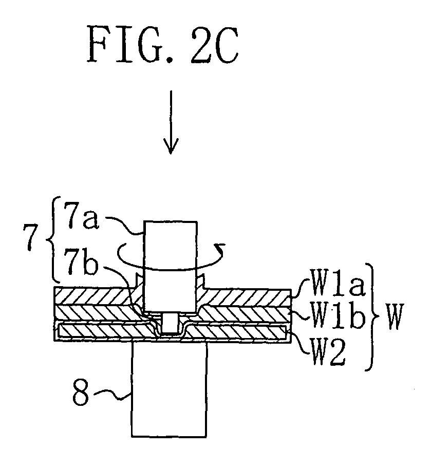
- FIG.2 shows a process of friction-spot-joining a work piece by the joining gun, wherein FIG. 2A is a diagram showing a state in which a rotary tool starts rotating; FIG. 2B is a diagram showing a state in which the rotary tool is thrust into a second steel plate;
- FIG. 2C is a diagram showing a state in which the rotary tool is thrust into a third steel plate; and FIG. 2D is a diagram showing a state in which the rotary tool is pulled out from the work piece.
- FIG. 3 is a list indicating compositions of a first steel plate in Working Examples and Comparative Examples.
- FIG. 4 is a diagram showing a friction spot joining of a work piece by the joining gun in Working Examples.
- FIG. 5 is a diagram showing a friction spot joining of a work piece by the joining gun in Comparative Examples.
- FIG. 6 is a list indicating joining conditions in friction spot joining of a work piece by the joining gun, the tensile shearing strengths of joints, and evaluation results in Working Examples and Comparative Examples.
- FIG. 7 is a graph showing the tensile shearing strengths of the joints in Working Examples.
- FIG. 8 is a graph showing the tensile shearing strengths of the joints in Comparative Examples.
- FIG. 9 is a diagram showing a modified example of the rotary tool.
- FIG. 10 is a diagram showing another modified example of the rotary tool.
- Embodiments of the present invention will be described below in detail with reference to the accompanying drawings.
- FIG. 1 is a schematic diagram showing a construction of a joining
gun 1 in the present embodiment. As shown in FIG. 1, the joininggun 1 includes a joiningunit 2 as a friction spot joining apparatus and agripping frame 3 mounted at, for example, a wrist of a robot (not shown). The joininggun 1 spot-joins, in a solid sate (a state in which each steel plate W1, W2 (see FIG. 2) are not melted), a plurality of steel plates W1, W2 of a work piece W used for a car body of an automobile in such a fashion that the plurality of steel plates W1, W2 are overlaid at least partially in the thickness direction. In the present embodiment, the steel plate W1 includes two first non-coated steel plates W1a, W1b, and the steel plate W2 is one second metal-coated steel plate. The first steel plates W1a, W1b are made of high-tensile steel having a tensile strength of 340 MPa or larger while the second steel plate W2 is made of mild steel having a tensile strength smaller than 340 MPa. The two first steel plates W1a, W1b are used as an inner plate and a reinforcing plate for a car body while the one second steel plate W2 is used as an outer plate for the car body. - The joining
unit 2 includes anapparatus body 4, apressing shaft motor 5, and arotary shaft motor 6. Below theapparatus body 4, arotary tool 7 is mounted. Therotary tool 7 includes acylindrical shoulder part 7a and acylindrical pin 7b protruding downward from the central part at the bottom of theshoulder part 7a and having a diameter smaller than that of theshoulder part 7a. Therotary tool 7 is rotated around the rotation axis X by therotary shaft motor 6 and is moved up and down in the direction of the rotation axis X by thepressing shaft motor 5. Thepressing shaft motor 5 and therotary shaft motor 6 are connected to a control board (not shown) that controls them. - At the end of an
arm 3a in an L-shape in section of thegripping frame 3, a metal-made (steel-made) cylindrical receivingmember 8 is mounted. To-be-joined part of the work piece W is clipped between therotary tool 7 and the receivingmember 8. The diameter of the receivingmember 8 is set larger than the diameter of theshoulder part 7a of therotary tool 7. - Description will be given below with reference to FIG. 2 to a process of friction-spot-joining the work piece W by the joining
gun 1. - First, as shown in FIG. 2A, the second metal-coated steel plate W2 and the first non-coated steel plates W1b, W1a are overlaid in this order to form the work piece W, and the receiving
member 8 is allowed to receive the to-be-joined part of the work piece W with the second steel plate W2 of the work piece W set against the receivingmember 8. In other words, the three steel plates W1a, W1b, W2 are overlaid on the receivingmember 8 in a state in which one (the upper one) of two steel plates located on the respective sides in the overlaying direction (vertical direction in FIG.2) is the first steel plate W1a while the other (the lower one in FIG. 2) is the second plate W2. - Next, when the rotary shaft motor 6 (see FIG.1) is driven, the
rotary tool 7 is rotated around the rotation axis X (see FIG. 1). - After the number of rotation of the
rotary tool 7 reaches a target number of rotation, the pressing shaft motor 5 (see FIG. 1) is driven with therotary tool 7 rotated to move therotary tool 7 downward. - In this way, the
pressing shaft motor 5 is driven to move therotary tool 7 downward until thepin 7b is in contact with the surface of the work piece W, that is, the surface of the first non-coated steel plate W1a. Whereby, the to-be-joined part of the work piece W is clipped between therotary tool 7 and the receivingmember 8 and are pressed in the direction of the rotation axis X (downward in FIG. 2). This causes friction between therotating rotary tool 7 and the surface of the first steel plate W1a to generate frictional heat. The thus generated frictional heat is transferred from the first steel plate W1a to the first steel plate W1b and then to the second steel plate W2 to soften the first steel plate W1b and the second steel plate W2. - When the rotation and pressing of the
rotary tool 7 is continued, as shown in FIG. 2B and FIG. 2C, plastic flow is caused in the first and second steel plates W1a, W1b, and W2. The frictional heat is released from the receivingmember 8 having the diameter larger than the diameter of theshoulder part 7a. - After the plastic flow is allowed to be generated in the work piece W for a predetermined period of time, the
pressing shaft motor 5 is reversed to raise therotating rotary tool 7 with therotary tool 7 rotated, so that therotary tool 7 is pulled out from the work W, as shown in FIG. 2D. - Thereafter, the work piece W is cooled (left for cooling) to be hardened, thereby completing joining of the work piece W.
- It is noted that the pressure and the number of rotation of the
rotary tool 7 and the joining period are set in the above joining process so that the to-be-joined part of the work piece W does not reach a temperature at which the steel plates W1, W2 are melted by frictional heat, for example, so that it reaches a temperature at which an austenitic structure is generated. - Working Examples of the present invention will be described below.
- A stationary pressure unit having a servo motor as the pressure shaft motor was employed as the joining unit.
- A ceramic-made rotary tool was used as the rotary tool. The diameter of the shoulder part of the rotary tool was 10 mm. The diameter and the length of the pin of the rotary tool were 3 mm and 1.27 mm, respectively.
- High-tensile steel plates (
JIS 3135 SPFC980Y) on a 980 MPa level having a thickness of 1.0 mm were used as the first steel plates. The compositions of the first steel plates are indicated in FIG. 3. - A mild steel plate on a 270 MPa level was used as the second steel plate. The second steel plate was zinc-coated and was subjected to an alloying process to obtain a galvaneal steel plate having a coating weight of 55 g/m2 and a thickness of 0.7 mm. The melting point of the alloyed hot dip zinc coating, which depends on the content ratio of zinc to iron, is within the range between 530 and 600 °C.
- In Working Examples 1 and 2, one galvaneal steel plate (Zn-Fe coated mild steel plate) and two high-tensile steel plates (DP980) were overlaid in this order to form a work piece, as shown in FIG. 4, and the rotary tool was rotated and allowed to press the to-be-joined part of the work piece from above to friction-spot-join the to-be-joined part. The to-be-joined part of the work piece at joining was heated up to the temperature at which an austenite structure is generated by the frictional heat.
- In Comparative Examples 1, 2, and 3, two high-tensile steel plates and one galvaneal steel plate were overlaid in this order to form a work piece, as shown in FIG. 5, and the rotary tool was rotated and allowed to press the to-be-joined part of the work piece from above to friction-spot-join the to-be-joined part. The to-be-joined part of the work piece at joining was heated up to the temperature at which an austenite structure is generated by the frictional heat, likewise Working Examples.
- As indicated in FIG. 6, the pressure and the number of rotation of the rotary tool were set to 19.6 kN and 1000 rpm, respectively, and the joining period was set to 3.0 s in Working Example 1.
- In Working Example 2, the pressure and the number of rotation of the rotary tool were set to 19.6 kN and 3000 rpm, respectively, and the joining period was set to 5.0 s.
- In Comparative Example 1, the pressure and the number of rotation of the rotary tool were set to 19.6 kN and 1000 rpm, respectively, and the joining period was set to 5.0 s.
- In Comparative Example 2, the pressure and the number of rotation of the rotary tool were set to 19.6 kN and 3000 rpm, respectively, and the joining period was set to 5.0 s.
- In Comparative Example 3, the pressure and the number of rotation of the rotary tool were set to 19.6 kN and 1000 rpm, respectively, and the joining period was set to 3.0 s.
- A tensile strength test was performed on each joint between the upper plates and the middle plates and each joint between the middle plates and the lower plates of the work pieces after joining, and the tensile shearing strength of each joint is measured.
- Evaluation was made by comparing the tensile shearing strengths of the joints with the resistance spot welding JIS class A average values (hereinafter referred to as RSW JIS class A average values) concerning the conventional resistance spot welding.
- In Working Examples 1 and 2, all the tensile shearing strengths at the respective joints were larger than the respective RSW JIS class A average values, as indicated in FIG. 6 and FIG. 7.
- In contrast, as indicated in FIG. 6 and FIG. 8, though all the tensile shearing strengths at the respective joint parts were larger than the respective RSW JIS class A average values in Comparative Example 1, the tensile shearing strength of the joint between the upper plate and the middle plate was larger than but that of the joint between the middle plate and the lower plate was smaller than the respective RSW JIS class A average values in Comparative Example 2. Specifically, in Comparative Example 2, the tensile shearing strength of the to-be-joined part between the high-tensile steel plates was smaller than the corresponding RSW JIS class A average values. Similarly to Comparative Example 2, the tensile shearing strength of the to-be-joined part between the middle plate and the lower plate was smaller than the corresponding RSW JIS class A average values in Comparative Example 3.
- As described above, in the present embodiment, the plurality of steel plates W1a, W1b, W2 are overlaid in such a fashion that at least one of the two steel plates located on the respective sides in the overlaying direction is the first steel plate W1a, and the
rotary tool 7 is rotated and allowed to press the to-be-joined part of the overlaid plural steel plates W1a, W1b, W2 from the first non-coated steel plate W1a side. Accordingly, therotary tool 7 hardly slips and frictional heat is readily generated, thereby suppressing elongation of time required for joining. Further, rotation and pressing of therotary tool 7 from the first non-coated steel plate W1a side less melts and evaporates the low-melting-point metal coating intervening between the steel plates W1 and W2, thereby suppressing lowering of the corrosion resistance of the second metal-coated steel plate W2. Thus, both elongation of time required for joining and lowering of the corrosion resistance of the metal-coated steel plate W2 are suppressed. - Moreover, the following arrangement achieves release of the frictional heat from the receiving
member 8. Namely: the receivingmember 8 is prepared which has a diameter larger than theshoulder part 7a of therotary tool 7; the plurality of steel plates W1a, W1b, W2 are overlaid in such a fashion that one of the two steel plates located on the respective sides in the overlaying direction is the first non-coated steel plate W1a while the other is the second metal-coated steel plate W2; the receivingmember 8 is allowed to receive the to-be-joined part of the plurality of overlaid steel plates W1a, W1b, W2 in such a fashion that the second metal-coated steel plate W2 is set against the receivingmember 8; and therotary tool 7 is rotated and allowed to press the to-be-joined part from the first non-coated steel plate W1a side. Release of the frictional heat results in further less melting and evaporation of the metal coating of the second steel plate W2 on the side against the receivingmember 8, thereby suppressing lowering of the corrosion resistance of the second metal-coated steel plate W2 definitely. - Furthermore, the
rotary tool 7 is rotated and allowed to press the to-be-joined part of the plurality of overlaid steel plates W1a, W1b, W2 from the non-coated high-tensile steel plate W1a side, which has high material strength and less plastic flowability, so as to cause sufficient plastic flow at the to-be-joined part of the high-tensile steel plate W1a. This increases the joint strength between the non-coated high-tensile steel plates W1a, W1b and the metal-coated mild steel plate W2. - As well, the joint strength among the two non-coated high-tensile steel plates W1a, W1b used for a car body and the one metal-coated mild steel plate W2 used for the car body can be increased. In addition, any dimple (see FIG. 2), which has been formed by the rotation and pressing of the
rotary tool 7, is not formed in the outer face of the metal-coated mild steel plate W2 used as an outer plate for a car body, thereby securing the appearance of the car body. - In the above embodiment, the work piece W is used for a car body of an automobile, but may be used for any other article.
- The work piece W is composed of the two first steel plates W1a, W1b and the one second steel plate W2 in the above embodiment, but the present invention is not limited thereto. The number of the first steel plates W1 may be one or plural, and the number of the second steel plates W2 may be one or plural as well. For example, the work piece W may be composed of one first steel plate W1 and one second steel plate W2. In this case, the first steel plate W1 and the second steel plate W2 are used as an inner plate and outer plate for a car body, respectively.
- In the above embodiment, the three steel plates W1a, W1b, W2 are overlaid in such a fashion that one of the two steel plates located on the respective sides in the overlaying direction is the first steel plate W1a while the other is the second steel plate W2. The present invention only requires an arrangement in which the plurality of steel plates W1, W2 are overlaid in such a fashion that at least one of the two steel plates located on the respective sides in the overlaying direction is the first steel plate W1 so that the
rotating rotary tool 7 presses the to-be-joined part of the plurality of overlaid steel plates W1, W2 from the first steel plate W1 side. - Further, the diameter of the receiving
member 7 is set larger than the diameter of theshoulder part 7a of therotary tool 7 in the above embodiment, but may be set equal to or smaller than that of theshoulder part 7a thereof. - In the above embodiment, the
rotary tool 7 includes theshoulder part 7a and thepin 7b. The present invention is not limited thereto, and theshoulder part 7a may have two stages as shown in FIG. 9 or may be formed in a helical form as shown in FIG. 10. - The present invention is not limited to the embodiments, and any other different embodiments may be made without departing from the sprit and scope of the present invention.
- The above embodiments are mere preferred examples in every aspect and should not be construed definitely. The scope of the invention is to be determined by the following claims, and the description imposes no constraint on the present invention. In addition, any modifications and variations belonging to the scope equivalent to the claims may be made within the scope of the present invention.
- As described above, the friction spot joining method in accordance with the present invention is applicable to fields necessitating suppression of both elongation of time required for joining and lowering of the corrosion resistance of a metal-coated steel plate.
Claims (7)
- A friction spot joining method in which a plurality of steel plates (W) are overlaid and a to-be-joined part of the plurality of overlaid steel plates (W) is friction-spot-joined in a solid state by causing plastic flow at the to-be-joined part by frictional heat generated by rotating a rotary tool (7) and allowing it to press the to-be-joined part, comprising the steps of:preparing, as the plurality of steel plate, at least one first non-coated steel plate (W1) and at least one second metal-coated steel plate (W2);overlaying the plurality of steel plates in such a fashion that at least one of two steel plates located on respective sides in an overlaying direction is the first non-coated steel plate (W1); androtating the rotary tool (7) and allowing it to press the to-be-joined part of the plurality of overlaid steel plates from the first non-coated steel plate side (W1).
- The friction spot joining method of Claim 1,wherein in the overlaying step, the plurality of steel plates are overlaid in such a fashion that one of the two steel plates located on the respective sides in the overlaying direction is the first non-coated steel plate (W1) while the other is the second metal-coated steel plate (W2),the method further comprising the steps of:preparing a receiving member (8) having a diameter larger than a diameter of a shoulder part (7a) of the rotary tool (7); andallowing the receiving member (7) to receive the to-be-joined part of the plurality of overlaid steel plates in such a fashion that the second metal-coated steel plate (W2) is set against the receiving member (8).
- The friction spot joining method of Claim 1 or 2,wherein the first steel plate (W1) is a high-tensile steel plate, andthe second steel plate (W2) is a mild steel plate.
- The friction spot joining method of Claim 3,wherein in the steel plates preparing step, one non-coated high-tensile steel plate (W1) and one metal-coated mild steel plate (W2) are prepared as the plurality of steel plates.
- The friction spot joining method of Claim 4,wherein the non-coated high-tensile steel plate (W1) is used as an inner plate for a car body, andthe metal-coated mild steel plate (W2) is used as an outer plate for the car body.
- The friction spot joining method of Claim 3,wherein in the steel plates preparing step, two non-coated high-tensile steel plates (W1) and one metal-coated mild steel plate (W2) are prepared as the plurality of metal plates, andin the overlaying step, the two non-coated high-tensile plates (W1) and the one metal-coated mild steel plate (W2) are overlaid in this order.
- The friction spot joining method of Claim 6,wherein the two non-coated high-tensile steel plates (W1) are used as an inner plate and a reinforcing plate for a car body, respectively, andthe one metal-coated mild steel plate (W2) is used as an outer plate for the car body.
Applications Claiming Priority (1)
| Application Number | Priority Date | Filing Date | Title |
|---|---|---|---|
| JP2006252314A JP4770661B2 (en) | 2006-09-19 | 2006-09-19 | Friction spot welding method |
Publications (2)
| Publication Number | Publication Date |
|---|---|
| EP1902810A1 true EP1902810A1 (en) | 2008-03-26 |
| EP1902810B1 EP1902810B1 (en) | 2011-11-30 |
Family
ID=38830438
Family Applications (1)
| Application Number | Title | Priority Date | Filing Date |
|---|---|---|---|
| EP07015992A Ceased EP1902810B1 (en) | 2006-09-19 | 2007-08-14 | Friction stir spot welding method |
Country Status (4)
| Country | Link |
|---|---|
| US (1) | US20080067215A1 (en) |
| EP (1) | EP1902810B1 (en) |
| JP (1) | JP4770661B2 (en) |
| CN (1) | CN101147999B (en) |
Cited By (2)
| Publication number | Priority date | Publication date | Assignee | Title |
|---|---|---|---|---|
| US20150183053A1 (en) * | 2013-12-27 | 2015-07-02 | Uacj Corporation | Process for spot-joining stacked metal foils |
| US20210339337A1 (en) * | 2018-10-11 | 2021-11-04 | Kawasaki Jukogyo Kabushiki Kaisha | Friction stir joining device, method of operating the same and joint structure |
Families Citing this family (18)
| Publication number | Priority date | Publication date | Assignee | Title |
|---|---|---|---|---|
| US8317079B2 (en) * | 2008-10-08 | 2012-11-27 | GM Global Technology Operations LLC | Clinching method and tool for performing the same |
| JP2012218009A (en) * | 2011-04-05 | 2012-11-12 | Suzuki Motor Corp | Method of bonding dissimilar metal materials and bonded body of dissimilar metal materials |
| JP5826141B2 (en) * | 2012-09-18 | 2015-12-02 | 本田技研工業株式会社 | Friction stir welding method |
| JP2016215264A (en) * | 2015-05-26 | 2016-12-22 | 株式会社東芝 | Friction stir welding tool and friction stir welding apparatus |
| CN105252136B (en) * | 2015-11-23 | 2017-11-14 | 哈尔滨工业大学 | A kind of method that metal surface coating is realized using stirring friction treatment |
| JP6505618B2 (en) * | 2016-02-05 | 2019-04-24 | 株式会社東芝 | Friction stir welding method and joined body |
| JP6650801B2 (en) * | 2016-03-17 | 2020-02-19 | 川崎重工業株式会社 | Friction stir spot welding method and friction stir spot welding apparatus |
| CN107755876B (en) * | 2016-08-23 | 2021-01-01 | 苹果公司 | Joining components having different structural compositions by friction stir welding |
| JP2019058933A (en) | 2017-09-27 | 2019-04-18 | 日本軽金属株式会社 | Manufacturing method of liquid-cooled jacket |
| JP2019058934A (en) | 2017-09-27 | 2019-04-18 | 日本軽金属株式会社 | Manufacturing method of liquid-cooled jacket |
| JP6978294B2 (en) * | 2017-11-30 | 2021-12-08 | 矢崎総業株式会社 | Terminal connection method and terminal |
| JP6769427B2 (en) | 2017-12-18 | 2020-10-14 | 日本軽金属株式会社 | How to manufacture a liquid-cooled jacket |
| JP6927128B2 (en) | 2018-04-02 | 2021-08-25 | 日本軽金属株式会社 | How to manufacture a liquid-cooled jacket |
| JP2019181473A (en) | 2018-04-02 | 2019-10-24 | 日本軽金属株式会社 | Liquid-cooled jacket manufacturing method |
| JP7070389B2 (en) | 2018-12-19 | 2022-05-18 | 日本軽金属株式会社 | Joining method |
| JP7223651B2 (en) * | 2019-07-01 | 2023-02-16 | 川崎重工業株式会社 | Welding system and its operation method |
| JP7160864B2 (en) * | 2020-07-15 | 2022-10-25 | フタバ産業株式会社 | Resistance spot welding method and resistance spot welding device |
| DE102023000731A1 (en) | 2023-03-01 | 2024-09-05 | Jonathan Rodemers | Process for joining woven materials to metals using soft metals and/or their alloys |
Citations (4)
| Publication number | Priority date | Publication date | Assignee | Title |
|---|---|---|---|---|
| JP2002210564A (en) | 2001-01-18 | 2002-07-30 | Nippon Yakin Kogyo Co Ltd | Painted plate welding method |
| EP1375050A1 (en) | 2001-03-29 | 2004-01-02 | Kawasaki Jukogyo Kabushiki Kaisha | Machining control method, machining control device, computer program for executing the method, and information storage medium having the computer program stored therein |
| EP1498210A1 (en) * | 2003-07-15 | 2005-01-19 | Mazda Motor Corporation | Friction stir welding method and friction stir welded structure |
| JP2006021217A (en) | 2004-07-07 | 2006-01-26 | Kawasaki Heavy Ind Ltd | Friction stir welding equipment for spot welding |
Family Cites Families (14)
| Publication number | Priority date | Publication date | Assignee | Title |
|---|---|---|---|---|
| US5729463A (en) * | 1995-09-01 | 1998-03-17 | Ulsab Trust | Designing and producing lightweight automobile bodies |
| JP3681156B2 (en) * | 2000-05-10 | 2005-08-10 | 住友軽金属工業株式会社 | Spot joint and spot joint method |
| JP2002273579A (en) * | 2001-03-15 | 2002-09-25 | Hitachi Ltd | Method of joining iron-based material and its structure |
| JP3785105B2 (en) * | 2002-03-18 | 2006-06-14 | 住友軽金属工業株式会社 | Dissimilar metal member joining method |
| JP2004276724A (en) * | 2003-03-14 | 2004-10-07 | Tokyu Car Corp | Car body for rolling stock and its manufacturing method |
| JP2005021931A (en) * | 2003-06-30 | 2005-01-27 | Tokyu Car Corp | Lap joining method and lap joining structure of plate materials |
| JP4479416B2 (en) * | 2004-08-25 | 2010-06-09 | マツダ株式会社 | Friction spot welding method and apparatus |
| JP4729921B2 (en) * | 2004-12-24 | 2011-07-20 | マツダ株式会社 | Friction spot welding method and apparatus |
| JP4804011B2 (en) * | 2005-02-02 | 2011-10-26 | 住友軽金属工業株式会社 | Friction stir spot welding method |
| JP2006224146A (en) * | 2005-02-17 | 2006-08-31 | Kobe Steel Ltd | Dissimilar material joining method |
| JP4672434B2 (en) * | 2005-05-18 | 2011-04-20 | 住友軽金属工業株式会社 | Friction stir spot welding method |
| US20070039154A1 (en) * | 2005-08-02 | 2007-02-22 | Mazda Motor Corporation | Frictional spot joining method and frictional spot joining apparatus |
| JP4869817B2 (en) * | 2006-07-28 | 2012-02-08 | 川崎重工業株式会社 | Friction stir welding equipment |
| WO2008023500A1 (en) * | 2006-08-21 | 2008-02-28 | Osaka University | Process for working metal members and structures |
-
2006
- 2006-09-19 JP JP2006252314A patent/JP4770661B2/en not_active Expired - Fee Related
-
2007
- 2007-08-09 CN CN2007101407585A patent/CN101147999B/en not_active Expired - Fee Related
- 2007-08-10 US US11/889,233 patent/US20080067215A1/en not_active Abandoned
- 2007-08-14 EP EP07015992A patent/EP1902810B1/en not_active Ceased
Patent Citations (4)
| Publication number | Priority date | Publication date | Assignee | Title |
|---|---|---|---|---|
| JP2002210564A (en) | 2001-01-18 | 2002-07-30 | Nippon Yakin Kogyo Co Ltd | Painted plate welding method |
| EP1375050A1 (en) | 2001-03-29 | 2004-01-02 | Kawasaki Jukogyo Kabushiki Kaisha | Machining control method, machining control device, computer program for executing the method, and information storage medium having the computer program stored therein |
| EP1498210A1 (en) * | 2003-07-15 | 2005-01-19 | Mazda Motor Corporation | Friction stir welding method and friction stir welded structure |
| JP2006021217A (en) | 2004-07-07 | 2006-01-26 | Kawasaki Heavy Ind Ltd | Friction stir welding equipment for spot welding |
Cited By (5)
| Publication number | Priority date | Publication date | Assignee | Title |
|---|---|---|---|---|
| US20150183053A1 (en) * | 2013-12-27 | 2015-07-02 | Uacj Corporation | Process for spot-joining stacked metal foils |
| US9302343B2 (en) * | 2013-12-27 | 2016-04-05 | Uacj Corporation | Process for spot-joining stacked metal foils |
| US20210339337A1 (en) * | 2018-10-11 | 2021-11-04 | Kawasaki Jukogyo Kabushiki Kaisha | Friction stir joining device, method of operating the same and joint structure |
| US12168261B2 (en) * | 2018-10-11 | 2024-12-17 | Kawasaki Jukogyo Kabushiki Kaisha | Friction stir joining device, method of operating the same and joint structure |
| US12496655B2 (en) | 2018-10-11 | 2025-12-16 | Kawasaki Jukogyo Kabushiki Kaisha | Friction stir joining device, method of operating the same and joint structure |
Also Published As
| Publication number | Publication date |
|---|---|
| CN101147999B (en) | 2012-01-04 |
| CN101147999A (en) | 2008-03-26 |
| US20080067215A1 (en) | 2008-03-20 |
| JP4770661B2 (en) | 2011-09-14 |
| EP1902810B1 (en) | 2011-11-30 |
| JP2008073693A (en) | 2008-04-03 |
Similar Documents
| Publication | Publication Date | Title |
|---|---|---|
| EP1902810B1 (en) | Friction stir spot welding method | |
| Mallick | Joining for lightweight vehicles | |
| KR100785557B1 (en) | Steel sheet for dissimilar materials weldbonding to aluminum material and dissimilar materials bonded body | |
| US8960523B2 (en) | Friction stir welding of dissimilar metals | |
| US20090291322A1 (en) | Joined body and process for manufacturing the same | |
| Meschut et al. | Innovative joining technologies for multi-material structures | |
| EP1291115B1 (en) | Interface preparation for weld joints | |
| Yang et al. | Friction self-piercing riveting (F-SPR) of aluminum alloy to magnesium alloy using a flat die | |
| US20100089977A1 (en) | Friction stir welding of dissimilar metals | |
| Lazarevic et al. | Experimental analysis of friction stir forming for dissimilar material joining application | |
| CN109746560B (en) | Welding electrode | |
| Fujimoto et al. | Development of friction spot joining | |
| US20090261146A1 (en) | Donor material technology for friction stir welding | |
| JP7526404B2 (en) | Method for joining metal materials | |
| CN110202245B (en) | Improving Mechanical Properties of Aluminum-Steel Welds by Limiting Plate Deformation | |
| Sahin et al. | Mechanical and metalurgical properties of friction welded aluminium joints | |
| JP2009113077A (en) | Friction spot welding method | |
| JP2008212984A (en) | Friction spot joining method and friction spot joining structure | |
| JP7570998B2 (en) | Method for manufacturing metal joint | |
| Yasui et al. | Characteristics of High Speed Welding between 6063 and S 45 C by Means of Friction Stirring-Study on Welding in Dissimilar Metals by Means of Friction Stirring(1 st Report)- | |
| GB2636506A (en) | Welded body, method for friction stir spot welding, and device for friction stir spot welding | |
| Li et al. | Friction self-piercing riveting (F-SPR) of AA6061-T6 to AZ31B | |
| Đurić et al. | Tensile-shear testing of resistance element welded joint of carbon fiber-reinforced polymer and DP500 steel | |
| Suzuki et al. | Dissimilar metals Joining Process using GMAW has High strength and One side access characteristic, and the Automation robot system | |
| JP7586993B1 (en) | Method for manufacturing metal joint |
Legal Events
| Date | Code | Title | Description |
|---|---|---|---|
| PUAI | Public reference made under article 153(3) epc to a published international application that has entered the european phase |
Free format text: ORIGINAL CODE: 0009012 |
|
| AK | Designated contracting states |
Kind code of ref document: A1 Designated state(s): AT BE BG CH CY CZ DE DK EE ES FI FR GB GR HU IE IS IT LI LT LU LV MC MT NL PL PT RO SE SI SK TR |
|
| AX | Request for extension of the european patent |
Extension state: AL BA HR MK YU |
|
| 17P | Request for examination filed |
Effective date: 20080710 |
|
| 17Q | First examination report despatched |
Effective date: 20080807 |
|
| AKX | Designation fees paid |
Designated state(s): DE |
|
| GRAP | Despatch of communication of intention to grant a patent |
Free format text: ORIGINAL CODE: EPIDOSNIGR1 |
|
| GRAS | Grant fee paid |
Free format text: ORIGINAL CODE: EPIDOSNIGR3 |
|
| GRAA | (expected) grant |
Free format text: ORIGINAL CODE: 0009210 |
|
| AK | Designated contracting states |
Kind code of ref document: B1 Designated state(s): DE |
|
| REG | Reference to a national code |
Ref country code: DE Ref legal event code: R096 Ref document number: 602007019012 Country of ref document: DE Effective date: 20120301 |
|
| REG | Reference to a national code |
Ref country code: DE Ref legal event code: R084 Ref document number: 602007019012 Country of ref document: DE Effective date: 20111206 |
|
| PLBE | No opposition filed within time limit |
Free format text: ORIGINAL CODE: 0009261 |
|
| STAA | Information on the status of an ep patent application or granted ep patent |
Free format text: STATUS: NO OPPOSITION FILED WITHIN TIME LIMIT |
|
| 26N | No opposition filed |
Effective date: 20120831 |
|
| REG | Reference to a national code |
Ref country code: DE Ref legal event code: R097 Ref document number: 602007019012 Country of ref document: DE Effective date: 20120831 |
|
| PGFP | Annual fee paid to national office [announced via postgrant information from national office to epo] |
Ref country code: DE Payment date: 20200804 Year of fee payment: 14 |
|
| REG | Reference to a national code |
Ref country code: DE Ref legal event code: R119 Ref document number: 602007019012 Country of ref document: DE |
|
| PG25 | Lapsed in a contracting state [announced via postgrant information from national office to epo] |
Ref country code: DE Free format text: LAPSE BECAUSE OF NON-PAYMENT OF DUE FEES Effective date: 20220301 |