EP1901498A2 - Mobile communication system and communication method thereof - Google Patents
Mobile communication system and communication method thereof Download PDFInfo
- Publication number
- EP1901498A2 EP1901498A2 EP20070114303 EP07114303A EP1901498A2 EP 1901498 A2 EP1901498 A2 EP 1901498A2 EP 20070114303 EP20070114303 EP 20070114303 EP 07114303 A EP07114303 A EP 07114303A EP 1901498 A2 EP1901498 A2 EP 1901498A2
- Authority
- EP
- European Patent Office
- Prior art keywords
- path
- data
- paths
- radio network
- network controller
- Prior art date
- Legal status (The legal status is an assumption and is not a legal conclusion. Google has not performed a legal analysis and makes no representation as to the accuracy of the status listed.)
- Withdrawn
Links
Images


Classifications
-
- H—ELECTRICITY
- H04—ELECTRIC COMMUNICATION TECHNIQUE
- H04W—WIRELESS COMMUNICATION NETWORKS
- H04W40/00—Communication routing or communication path finding
- H04W40/02—Communication route or path selection, e.g. power-based or shortest path routing
- H04W40/12—Communication route or path selection, e.g. power-based or shortest path routing based on transmission quality or channel quality
-
- H—ELECTRICITY
- H04—ELECTRIC COMMUNICATION TECHNIQUE
- H04B—TRANSMISSION
- H04B7/00—Radio transmission systems, i.e. using radiation field
- H04B7/24—Radio transmission systems, i.e. using radiation field for communication between two or more posts
- H04B7/26—Radio transmission systems, i.e. using radiation field for communication between two or more posts at least one of which is mobile
- H04B7/2612—Arrangements for wireless medium access control, e.g. by allocating physical layer transmission capacity
-
- H—ELECTRICITY
- H04—ELECTRIC COMMUNICATION TECHNIQUE
- H04L—TRANSMISSION OF DIGITAL INFORMATION, e.g. TELEGRAPHIC COMMUNICATION
- H04L1/00—Arrangements for detecting or preventing errors in the information received
- H04L1/0001—Systems modifying transmission characteristics according to link quality, e.g. power backoff
-
- H—ELECTRICITY
- H04—ELECTRIC COMMUNICATION TECHNIQUE
- H04L—TRANSMISSION OF DIGITAL INFORMATION, e.g. TELEGRAPHIC COMMUNICATION
- H04L1/00—Arrangements for detecting or preventing errors in the information received
- H04L1/08—Arrangements for detecting or preventing errors in the information received by repeating transmission, e.g. Verdan system
-
- H—ELECTRICITY
- H04—ELECTRIC COMMUNICATION TECHNIQUE
- H04L—TRANSMISSION OF DIGITAL INFORMATION, e.g. TELEGRAPHIC COMMUNICATION
- H04L45/00—Routing or path finding of packets in data switching networks
-
- H—ELECTRICITY
- H04—ELECTRIC COMMUNICATION TECHNIQUE
- H04L—TRANSMISSION OF DIGITAL INFORMATION, e.g. TELEGRAPHIC COMMUNICATION
- H04L45/00—Routing or path finding of packets in data switching networks
- H04L45/12—Shortest path evaluation
- H04L45/121—Shortest path evaluation by minimising delays
-
- H—ELECTRICITY
- H04—ELECTRIC COMMUNICATION TECHNIQUE
- H04L—TRANSMISSION OF DIGITAL INFORMATION, e.g. TELEGRAPHIC COMMUNICATION
- H04L45/00—Routing or path finding of packets in data switching networks
- H04L45/24—Multipath
-
- H—ELECTRICITY
- H04—ELECTRIC COMMUNICATION TECHNIQUE
- H04L—TRANSMISSION OF DIGITAL INFORMATION, e.g. TELEGRAPHIC COMMUNICATION
- H04L45/00—Routing or path finding of packets in data switching networks
- H04L45/70—Routing based on monitoring results
-
- H—ELECTRICITY
- H04—ELECTRIC COMMUNICATION TECHNIQUE
- H04W—WIRELESS COMMUNICATION NETWORKS
- H04W24/00—Supervisory, monitoring or testing arrangements
-
- H—ELECTRICITY
- H04—ELECTRIC COMMUNICATION TECHNIQUE
- H04W—WIRELESS COMMUNICATION NETWORKS
- H04W4/00—Services specially adapted for wireless communication networks; Facilities therefor
- H04W4/06—Selective distribution of broadcast services, e.g. multimedia broadcast multicast service [MBMS]; Services to user groups; One-way selective calling services
-
- H—ELECTRICITY
- H04—ELECTRIC COMMUNICATION TECHNIQUE
- H04W—WIRELESS COMMUNICATION NETWORKS
- H04W48/00—Access restriction; Network selection; Access point selection
- H04W48/08—Access restriction or access information delivery, e.g. discovery data delivery
-
- H—ELECTRICITY
- H04—ELECTRIC COMMUNICATION TECHNIQUE
- H04W—WIRELESS COMMUNICATION NETWORKS
- H04W68/00—User notification, e.g. alerting and paging, for incoming communication, change of service or the like
-
- H—ELECTRICITY
- H04—ELECTRIC COMMUNICATION TECHNIQUE
- H04W—WIRELESS COMMUNICATION NETWORKS
- H04W88/00—Devices specially adapted for wireless communication networks, e.g. terminals, base stations or access point devices
- H04W88/08—Access point devices
-
- H—ELECTRICITY
- H04—ELECTRIC COMMUNICATION TECHNIQUE
- H04W—WIRELESS COMMUNICATION NETWORKS
- H04W88/00—Devices specially adapted for wireless communication networks, e.g. terminals, base stations or access point devices
- H04W88/12—Access point controller devices
Definitions
- the present invention relates to a mobile communication system and communication method thereof, and more particularly to a mobile communication system and communication method thereof that, during handover, copies and transmi ts data to which transmission sequence numbers have been added from a mobile station to each of a plurality of paths going to a radio network control apparatus by way of a plurality of base stations.
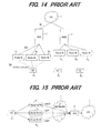
- a W-CDMA mobile communication system is a radio communication system in which a plurality of users shares lines, and as shown in FIG. 14, comprises: a core network (CN) 1, radio network controllers (RNC) 2, 3, radio base stations (Nodes B) 4 1 to 4 3 , 5 1 to 5 3 , and mobile stations (UE: User Equipment) 6 1 to 6 3 .
- the radio network controllers RNC and radio base stations (Nodes B) are connected by wired connections using an ATM network or IP network, and the radio base stations (Nodes B) and mobile stations UE are connected by radio connections.
- the core network 1 is a network for performing routing in a mobile communication system, and the core network 1 can be constructed using an ATM switching network, packet switching network, router network, etc.
- the core network 1 is also connected to other public networks (PSTN), which makes it possible for the mobile stations 6 1 to 6 3 to perform communication with fixed telephones.
- the radio network controllers (RNC) 2, 3, are positioned as superior devices of the radio base stations (hereafter referred to as base stations) 4 1 to 4 3 , 5 1 to 5 3 , and they perform control (management of the radio resources that are used) of these base stations.
- the RNC also has a handover control function that, during handover, receives a signal from one mobile station 6i by way of the plurality of base stations, then selects data having the best quality and transmits that data to the core network 1.
- the radio resources for the base stations 4 1 to 4 3 are managed by the RNC 2 and the radio resources for the base stations 5 1 to 5 3 are managed by the RNC 3, while the base stations 4 1 to 4 3 and 5 1 to 5 3 perform radio communication with a mobile station 6i.
- a mobile station 6i is within the radio area of a base station, a radio connection is established with that base station, and communication is performed with another communication apparatus by way of the core network 1.
- An interface lu is set as the interface between the core network 1 and RNCs 2, 3, and the interface lub is set as the interface between the RNCs 2, 3 and each of the base stations 4 1 to 4 3 , 5 1 to 5 3 , and the interface Uu is set as the interface between the base stations 4 1 to 4 3 , 5 1 to 5 3 and the mobile stations 6 1 to 6 3 .
- the HSDPA High Speed Downlink Packet Access
- the HSUPA High Speed Uplink Packet Access
- the HSUPA method is a broadband data transmission function for the purpose of increasing performance of a dedicated channel when a mobile station transfers data in the UP direction, and particularly is a data transmission function used in the UP direction when the mobile station is in the handover state.
- FIG. 15 is a drawing that explains the logical connection of the HSUPA method during handover.
- the mobile station 6 is connected to the radio network controller 2 by a plural i ty of paths via base stations 4, to 4 3 and IP network 7, and the mobile station 6 makes a number of copies of the data to be transmitted that corresponds to the number of paths, then transmits the copied data to the radio network controller 2 via each of the paths.
- the mobile station 6 attaches a TSN (Transmission Sequence Number) that indicates the data transmission sequence to each data.
- TSN Transmission Sequence Number
- the mobile station 6 when transmitting data Xn to the core network 1, the mobile station 6 copies that data Xn a number of times that corresponds to the number of paths (three in the figure), attaches the same transmission sequence number (TSN) to each copy of the data Xn and transmits the data Xn to the RNC 2 via each of the paths.
- TSN transmission sequence number
- the RNC 2 receives the data Xn via each of the paths, rearranges the received data using the TSN, performs selection combining of the data and then transmits the selected data to the core network CN.
- the method for the RNC to use the plurality of identical data Xn received via the plurality of paths is not regulated, and that identical plurality of received data Xn can be arbitrarily handled by any method as long as the data transmission sequence is sufficiently assured based on the TSN.
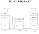
- FIG. 17 is a drawing showing the layer structure of each unit in the HSUPA method, where the mobile station (UE) comprises a physical layer (PHY) of layer L1 and MAC sub layers (MAC-d, MAC-es/MAC-e) of layer L2.
- the MAC sub layers comprise a MAC-d (MAC-dedicated) layer, MAC-e (MAC-enhanced) layer, and MAC-es layer (MAC-enhanced sub layer).
- the base station (Node B) comprises a physical layer (PHY) for communicating with a mobile station by the Uu interface, and a TNL layer (Transport Network Layer) for packet communication with the radio network controller (RNC) by the lub interface.
- RNC Radio Network Controller
- it comprises a MAC-e layer and EDCH FP (Enhanced DCH Frame Protocol) layer.
- the radio network controller comprises a TNL layer, EDCH FP layer, MAC-es layer and MAC-d layer.
- FIG. 18 is a drawing that explains the procedure for creating a data (transport block) TRB by the mobile station.
- the mobile station 6 uses data that is sent via a dedicated channel DCH such as a DTCH (Dedicated Traffic Channel) or DCCH (Dedicated Control Channel) to create a data packet (MAC-d PDU data) for the MAC-d layer.
- DCH dedicated Traffic Channel
- DCCH Dedicated Control Channel
- MAC-d PDU data MAC-d PDU data
- RLC PDU data Dedicated Control Channel
- the mobile station multiplexes several MAC-d PDU data, attaches a transmission sequence number TSN to the start, and creates the data (MAC-es PDU) of the MAC-es layer.
- the mobile station multiplexes a plurality of these MAC-es PDU data, attaches a MAC-e header to the start, creates the data (MAC-e PDU) of the MAC-e layer and transmits this data as a transport block TRB to the base station by the Uu interface.
- the MAC-e header specifies the DDI (Data Description Identifier) and N of each MAC-es PDU data, where N specifies the number of MAC-d PDU data that is included in the MAC-es PDU data, and DDI specifies the size and ID of each MAC-d PDU data.
- FIG. 19 is a drawing that explains the multiplexing relationship of the MAC-d PDU, MAC-es PDU and MAC-e PDU data, where N1 number of MAC-d PDU are multiplexed to create one MAC-es PDU, and n number of MAC-es PDU are multiplexed to create one MAC-e PDU.
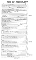
- the base station receives a transport block (MAC-e PDU) from the mobile station, it creates an EDCH lub FP frame as shown in FIG. 20 according to EDCH FP protocol, and transmits it to the RNC in a TNL layer.
- MAC-e PDU transport block
- the base station adds the starting 5-byte data (header CRC, FSN (Frame Sequence Number), CFN (Connection Frame Sequence) and N of MAC-es PDU (number of sub frames, etc.) to the MAC-e PDU header, adds the number of retransmissions of each MAC-es PDU (N of HARQ Retransm) to the MAC-e PDU header, and creates an EDCH lub FP frame. As shown in FIG.
- the radio network controller RNC receives an EDCH lub FP frame for each logical channel, the RNC performs retransmission control (HARQ control) and, in addition by reference to the MAC-e header it divides the MAC-e PDU into MAC-es PDU, and further divides the MAC-es PDU into MAC-d PDU.
- HARQ control retransmission control
- the radio network controller RNC performs rearrangement of the received data and selection combining of the data by reference to the transmission sequence number TSN that is attached to data by the mobile station when transmitting data, thereafter gives that rearranged MAC-d PDU to the RLC sub layer (higher-order protocol), and transmits dedicated-channel data to the core network via that RLC sub layer.
- the radio network controller monitors the communication state of each path, determines to transmit data over all of a plurality of paths, transmit data over two or more specified paths, or transmit data over only one specified path based on the communication state of each path, and notifies the mobile station of the determined path/paths; and the mobile station transmits the copied data over the notified path/paths, so it may be possible to control the amount of transmission data by changing the number of paths over which the copied data is transmitted in conformity with the communication state of the path/paths.
- the radio network controller by monitoring the line usage rate of each of the paths between the base stations and the radio network controller and transmitting data over a path/paths whose line usage rate is less than a set value and not transmitting data over a path/paths whose line usage rate is greater than a set value, it may be possible to avoid applying a large load to the Iub line, and thus it may be possible to eliminate adverse effects (lost or delayed packets) on other communication services. Also, according to an embodiment of the present invention, by dynamically changing the line which is used in conformity with the network environment, it may be possible to improve the data quality and the communication efficiency.
- the RNC by determining to transmit data over all paths, transmit data over two or more specified paths or transmit data over only one specified path based on the communication state, it may be possible to reduce the amount of data to be processed by the RNC in conformity with the communication state, as well as it may be possible to reduce the amount of transmission data transmitted and decrease the amount of power consumed by the mobile station.
- the radio network controller notifies the mobile station of a correlation list that correlates path information that indicates which path/paths data is to be transmitted over, and an identifier that specifies that path information, and the radio network controller uses that identifier to notify the mobile station of the path/paths over which data is to be transmitted, so it may be possible to notify the mobile station of the path/paths over which to transmit data without affecting the traffic.
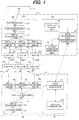
- FIG. 1 is a drawing showing part of the construction of the mobile communication system of the present invention, comprising: a core network (CN) 11, one radio network controller (RNC) 12, three radio base stations (Nodes B) 13 0 to 13 2 , and one mobile station (UE: User Equipment) 14, where the mobile station 14 reaches a cell boundary and is in a soft handover state, and it is connected wi th the RNC 12 via paths PT0 to PT2.
- the radio base stations (Nodes B) 13 1 to 13 3 exist in each of the paths PT0 to PT2, and communication is performed between the mobile station 14 and each of the base stations by way of the Uu interface, and communication is performed between each of the base stations 13 1 to 13 3 and the radio network controller 12 by way of the lub interface.
- the data flow is shown by the solid lines, and the flow of the control signals is shown by the dashed lines.
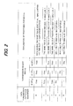
- FIG. 2 is a drawing explaining the path list PLT in a case where three paths are connected between a mobile station and radio network controller due to a handover.
- the MAC-es processing unit 33 (to be described in detail later) of the mobile station 14 makes three copies of the MAC-es PDU data for each time slot, attaches the same transmission sequence number TSN to each and inputs the data to the three MAC-e processing units 34 0 to 34 2 , and the MAC-e processing units create respective MAC-e data and transmit the data over the three paths PT0 to PT2 (3 GPP specifications).
- the MAC-es processing unit 33 of the mobile station 14 makes two copies of the MAC-es PDU data for each time slot, attaches the same transmission sequence number TSN to each and inputs the data to two specified MAC-e processing units 34 0 to 34 2 , and the MAC-e processing units create respective MAC-e data and transmit the data over two specified paths PT0 and PT1.
- the MAC-es processing unit 33 of the mobile station 14 does not copy the MAC-es PDU data, attaches the transmission sequence number TSN to the data and inputs the data to one MAC-e processing unit 34 0 , and that MAC-e processing unit creates MAC-e data and transmits it over one path PT0.
- the data transmission path determination/notification unit 29 transmits a path list PLT to the mobile station, and based on the lub line usage rate for each path, determines whether to transmit data over three paths PT0 to PT2, transmit data over two specified paths, or transmit data over one specified path, andusingan identifier notifies the mobile station of which path/paths was determined.
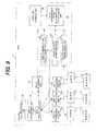
- FIG. 3 is a drawing explaining a sequence for explaining initial setting of the path list and identifier notification control.
- the data transmission path determination/notification unit 29 of the radio network controller 12 receives the path list PLT from the path list storage unit 28 (S01) and notifies the mobile station 14 (S02).
- the data transmission path ID unit 37 of the mobile station 14 notifies the path list storage unit 36 of the path list PLT that was sent from the radio network controller 12, and the path list storage unit 36 stores that path list (S03).
- the data transmission path determination/notification unit 29 makes an inquiry to the lub line usage rate monitoring unit 27 of the lub line usage status (S04), and based on the line usage rate of each lub line lub #0 to lub #2, calculates the optimal data transmission path/paths (S05).
- the data transmission path determination/notification unit 29 makes a reference to the path list PLT that is stored by the path list storage unit 28 to find the identifier that corresponds to the calculated transmission path/paths (S06), and notifies the mobile station 14 of that identifier (S07).
- the data transmission path ID unit 37 of the mobile station 14 makes a reference to the path list PLT that is stored by the path list storage unit 36, finds the data transmission path/paths specified by the identifier (S08) and sets that data transmission path/paths in the MAC-es processing unit 33 (S09).
- S08 the data transmission path/paths specified by the identifier
- S09 the data transmission path/paths in the MAC-es processing unit 33
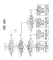
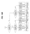
- FIG. 4A and FIG. 4B are flowcharts of the transmission path determination process of steps S05 to S06.
- the data transmission path determination/notification unit 29 checks whether the line usage rates ⁇ of lub #0, lub #1 and lub#2 are a set value, for example 80% or less.
- the line usage rate is the ratio of the maximum allowable bandwidth Bmax and the actually allotted bandwidth (used bandwidth) Buse, and can be calculated from the following equation.
- ⁇ Buse / Bmax ⁇ 100 %
- the data transmission path determination/notification unit 29 determines that communication is not possible (step 123).
- the MAC-es processing unit 33 makes three copies of the MAC-es PDU data according to an instruction from the data transmission path ID uni t 37, and inputs the data to the MAC-e processing unit 34 0 to 34 2 .
- FIG. 6 is a drawing for explaining the TSN that are assigned by the MAC-es processing unit 33 of the mobile station 14 for each time slot, and the transmission data image to MAC-e.
- the MAC-e processing units 34 0 to 34 2 multiplex a plurality of MAC-es PDU data to create MAC-e PDU data and transmi ts that data as transport block data over the corresponding paths PT0 to PT2. After that, the MAC-es processing unit 33 and MAC-e processing units 34 0 to 34 2 perform the same processing as described above for each time slot and transmit the copied data over paths PT0 to PT2. The transmission sequence number is incremented up one number at a time for each time slot.
- the MAC-es processing unit 23 of the radio network controller 12 divides out the MAC-d PDU data from the MAC-es PDU data that has been divided out from the MAC-e PDU data by each MAC-e processing unit, as well as rearranges the data by reference to the transmission sequence numbers TSN, then inputs that data to the MAC-d processing unit 24.
- the MAC-d processing unit 24 gives the MAC-d PDU data as is to the RLC processing unit 25 as RLC-PDU data, and the RLC processing unit 25 selects specified RLC-PDU data acquired from paths PT0 to PT2 and deletes unnecessary data, then removes the header from the selected RLC-PDU data resulting in dedicated data and transmits this dedicated data to the core network 11.
- the MAC-es processing unit 33 makes two copies of the MAC-es PDU data according to an instruction from the data transmission path ID unit 37, and inputs the data to the MAC-e processing units 34 0 to 34 1 .
- FIG. 8 is a drawing for explaining the TSN that are assigned by the MAC-es processing unit 33 of the mobile station 14 for each time slot, and the transmission data image to MAC-e.
- the MAC-e processing units 34 0 to 34 1 multiplex a plurality of MAC-es PDU data to create MAC-e PDU data and transmi ts that data as transport block data over the corresponding paths PT0 to PT1. After that, the MAC-es processing unit 33 and MAC-e processing units 34 0 to 34 1 perform the same processing as described above for each time slot and transmit the same data A1 to Ax over paths PT0 to PT1. The transmission sequence number is incremented up one number at a time for each time slot.
- the MAC-es processing unit 23 of the radio network controller 12 divides out the MAC-d PDU data from the MAC-es PDU data that has been divided out from the MAC-e PDU data by each MAC-e processing unit, as well as rearranges the data by reference to the transmission sequence numbers TSN, then inputs that data to the MAC-d processing unit 24.
- the MAC-d processing unit 24 gives the MAC-d PDU data as is to the RLC processing unit 25 as RLC-PDU data, and the RLC processing unit 25 selects specified RLC-PDU data acquired from paths PT0 to PT1 and deletes unnecessary data, then removes the header from the selected RLC-PDU data and transmits individual data to the core network 11.
- the data transmission path/paths were determined by the process shown in FIG. 4A and FIG. 4B based on the line usage rate, however, it is also possible to determine the data transmission path/paths by measuring other characteristics that indicate a network environment instead of using the line usage rate. Change in a network environment can be measured by (1) radio quality, (2) communication delay time between the RNC and Node B, (3) E-DCH throughput status, (4) lub quality, etc. Therefore, it is possible to perform control so that the data transmission path/paths are set by measuring these characteristics. Moreover, it is possible to perform control so that the data transmission path/paths are determined by measuring two or more of these characteristics.
- FIG. 9 is a drawing of the construction of a radio network controller 12 that measures the aforementioned characteristics and determines the data transmission path/paths, where the same reference numbers are given to parts that are the same as those of the construction shown in FIG. 1.
- This construction differs in that there is: a delay measurement unit 51 that measures the communication delay status between the RNC and Nodes B, a radio quality monitoring unit that monitors the radio quality between the mobile station and base stations, and a E-DCH communication quality monitoring unit 53 that monitors E-DCH throughput information or lub quality.
- the delay measurement unit 51 acquires the communication delay status between the RNC and Nodes B using a conventional function.
- the delay measurement unit 51 periodically transmits a packet for measuring delay to each base station and measures the time until a response is returned, then inputs that time to the data transmission path determination/notification unit 29 as the delay time of the lub line.
- the data transmission path determination/notification unit 29 determines that the communication quality of an lub line is good when the delay time is short.
- the radio quality monitoring unit 52 monitors the radio quality based on the N of HARQ Retransm (number of retransmissions in the radio zone) within the E-DCH lub FP frame shown in FIG. 20, and inputs the number of retransmissions to the data transmission path determination/notification unit 29.
- the data transmission path determination/notification unit 29 determines that the quality is poor when the number of retransmissions is greater than a set number, and that the quality is good when the number of transmissions is less than that set number.
- the E-DCH communication quality monitoring unit 53 monitors the frame amount of E-DCH lub FP (see FIG. 20) that the MAC-e processing units 22 0 to 22 2 received over a set period of time as E-DCH throughput information, and inputs that frame amount to the data transmission path determination/notification unit 29.
- the data transmission path determination/notification unit 29 determines that the communication quality of a line is good when the frame amount is greater than a set value.
- the E-DCH communication quality monitoring unit 53 checks the FSN continuity within the E-DCH lub FP (See FIG. 20), and inputs information indicating whether there is continuity or no continuity to the data transmission path determination/notification unit 29.
- the data transmission path determination/notification 29 unit determines that the quality is good when there is FSN continuity.
- FIG. 10 A and FIG.10B are flowcharts showing the processing performed by the data transmission path determination/notification unit 29 that determines the data transmission path/paths according to the communication delay time, where a combination of data transmission paths is determined so that when the communication delay time of a line is less than a set time, data is transmitted over that line, and when the delay time of a line is greater than a set time, data is not transferred over that line, an identifier ID that specifies that combination is then found and the mobile station is notified of that identifier ID.
- FIG. 10A and FIG. 10B are flowcharts of processing that follows the same logic as the processing shown in FIG. 4A and FIG.4B.
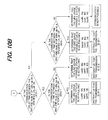
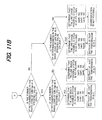
- FIG.11 A and FIG.11B are flowcharts showing the processing performed by the data transmission path determination/notification unit 29 that determines the data transmission path/paths according to the number of retransmissions, where a combination of data transmission paths is determined so that when the number of retransmissions of a line is less than a set number of times, data is transmitted over that line, and when greater than the set number of times, data is not transmitted over that line, an identifier ID that specifies that combination is then found and the mobile station is notified of that identifier ID.
- FIG.11 A and FIG.11B are flowcharts showing the processing performed by the data transmission path determination/notification unit 29 that determines the data transmission path/paths according to the number of retransmissions, where a combination of data transmission paths is determined so that when the number of retransmissions of a line is less than a set number of times, data is transmitted over that line, and when greater than the set number of times, data is not transmitted over that line, an identifier ID
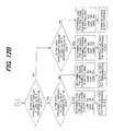
- FIG. 12A and FIG.12B are flowcharts showing the processing performed by the data transmission path determination/notification unit 29 that determines the data transmission path/paths according to the amount of data throughput, where a combination of data transmission paths is determined so that when the amount of throughput of a line is greater than a set value, data is transmitted over that line, and when less than the set number of time, data is not transmitted over that line, an identifier ID that specifies that combination is then found and the mobile station is notified of that identifier ID.
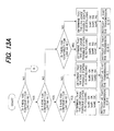
- 13B are flowcharts showing the processing performed by the data transmission path determination/notification unit 29 that determines the data transmission path/paths according to FSN continuity, where a combination of data transmission paths is determined so that when there is a line having FSN continuity, data is transmitted over that line, and when there is no FSN continuity, data is not transmitted over that line, an identifier ID that specifies that combination is then found and the mobile station is notified of that identifier ID.
- the invention also provides a computer program or a computer program product for carrying out any of the methods described herein, and a computer readable medium having stored thereon a program for carrying out any of the methods described herein.
- a computer program embodying the invention may be stored on a computer-readable medium, or it could, for example, be in the form of a signal such as a downloadable data signal provided from an Internet website, or it could be in any other form.
Abstract
Description
- The present invention relates to a mobile communication system and communication method thereof, and more particularly to a mobile communication system and communication method thereof that, during handover, copies and transmi ts data to which transmission sequence numbers have been added from a mobile station to each of a plurality of paths going to a radio network control apparatus by way of a plurality of base stations.
- A W-CDMA mobile communication system is a radio communication system in which a plurality of users shares lines, and as shown in FIG. 14, comprises: a core network (CN) 1, radio network controllers (RNC) 2, 3, radio base stations (Nodes
B) 41 to 43, 51 to 53, and mobile stations (UE: User Equipment) 61 to 63. The radio network controllers RNC and radio base stations (Nodes B) are connected by wired connections using an ATM network or IP network, and the radio base stations (Nodes B) and mobile stations UE are connected by radio connections.
Thecore network 1 is a network for performing routing in a mobile communication system, and thecore network 1 can be constructed using an ATM switching network, packet switching network, router network, etc. Thecore network 1 is also connected to other public networks (PSTN), which makes it possible for themobile stations 61 to 63 to perform communication with fixed telephones.
The radio network controllers (RNC) 2, 3, are positioned as superior devices of the radio base stations (hereafter referred to as base stations) 41 to 43, 51 to 53, and they perform control (management of the radio resources that are used) of these base stations. The RNC also has a handover control function that, during handover, receives a signal from one mobile station 6i by way of the plurality of base stations, then selects data having the best quality and transmits that data to thecore network 1. The radio resources for thebase stations 41 to 43 are managed by theRNC 2 and the radio resources for thebase stations 51 to 53 are managed by theRNC 3, while thebase stations 41 to 43 and 51 to 53 perform radio communication with a mobile station 6i. When a mobile station 6i is within the radio area of a base station, a radio connection is established with that base station, and communication is performed with another communication apparatus by way of thecore network 1. - An interface lu is set as the interface between the
core network 1 andRNCs RNCs base stations 41 to 43, 51 to 53, and the interface Uu is set as the interface between thebase stations 41 to 43, 51 to 53 and themobile stations 61 to 63.
In this mobile communication system, in order to make high speed data transmission in the DOWN direction possible, the HSDPA (High Speed Downlink Packet Access) method is used, and in order to make high speed data transmission in the UP direction possible, the HSUPA (High Speed Uplink Packet Access) method is proposed. The HSUPA method is a broadband data transmission function for the purpose of increasing performance of a dedicated channel when a mobile station transfers data in the UP direction, and particularly is a data transmission function used in the UP direction when the mobile station is in the handover state. - FIG. 15 is a drawing that explains the logical connection of the HSUPA method during handover. The
mobile station 6 is connected to theradio network controller 2 by a plural i ty of paths viabase stations 4, to 43 andIP network 7, and themobile station 6 makes a number of copies of the data to be transmitted that corresponds to the number of paths, then transmits the copied data to theradio network controller 2 via each of the paths. When doing this, themobile station 6 attaches a TSN (Transmission Sequence Number) that indicates the data transmission sequence to each data. In other words, as shown in FIG. 16, when transmitting data Xn to thecore network 1, themobile station 6 copies that data Xn a number of times that corresponds to the number of paths (three in the figure), attaches the same transmission sequence number (TSN) to each copy of the data Xn and transmits the data Xn to theRNC 2 via each of the paths.
TheRNC 2 receives the data Xn via each of the paths, rearranges the received data using the TSN, performs selection combining of the data and then transmits the selected data to the core network CN. In the HSPUA system, the method for the RNC to use the plurality of identical data Xn received via the plurality of paths is not regulated, and that identical plurality of received data Xn can be arbitrarily handled by any method as long as the data transmission sequence is sufficiently assured based on the TSN. - FIG. 17 is a drawing showing the layer structure of each unit in the HSUPA method, where the mobile station (UE) comprises a physical layer (PHY) of layer L1 and MAC sub layers (MAC-d, MAC-es/MAC-e) of layer L2. The MAC sub layers comprise a MAC-d (MAC-dedicated) layer, MAC-e (MAC-enhanced) layer, and MAC-es layer (MAC-enhanced sub layer). The base station (Node B) comprises a physical layer (PHY) for communicating with a mobile station by the Uu interface, and a TNL layer (Transport Network Layer) for packet communication with the radio network controller (RNC) by the lub interface. Moreover, it comprises a MAC-e layer and EDCH FP (Enhanced DCH Frame Protocol) layer. The radio network controller comprises a TNL layer, EDCH FP layer, MAC-es layer and MAC-d layer.
- FIG. 18 is a drawing that explains the procedure for creating a data (transport block) TRB by the mobile station. First, the
mobile station 6 uses data that is sent via a dedicated channel DCH such as a DTCH (Dedicated Traffic Channel) or DCCH (Dedicated Control Channel) to create a data packet (MAC-d PDU data) for the MAC-d layer. This MAC-d PDU data is the same as the data packet (RLC PDU data) of the RLC sub layer. Next, the mobile station multiplexes several MAC-d PDU data, attaches a transmission sequence number TSN to the start, and creates the data (MAC-es PDU) of the MAC-es layer. After that, the mobile station multiplexes a plurality of these MAC-es PDU data, attaches a MAC-e header to the start, creates the data (MAC-e PDU) of the MAC-e layer and transmits this data as a transport block TRB to the base station by the Uu interface. The MAC-e header specifies the DDI (Data Description Identifier) and N of each MAC-es PDU data, where N specifies the number of MAC-d PDU data that is included in the MAC-es PDU data, and DDI specifies the size and ID of each MAC-d PDU data. - FIG. 19 is a drawing that explains the multiplexing relationship of the MAC-d PDU, MAC-es PDU and MAC-e PDU data, where N1 number of MAC-d PDU are multiplexed to create one MAC-es PDU, and n number of MAC-es PDU are multiplexed to create one MAC-e PDU.
When the base station receives a transport block (MAC-e PDU) from the mobile station, it creates an EDCH lub FP frame as shown in FIG. 20 according to EDCH FP protocol, and transmits it to the RNC in a TNL layer. In other words, the base station adds the starting 5-byte data (header CRC, FSN (Frame Sequence Number), CFN (Connection Frame Sequence) and N of MAC-es PDU (number of sub frames, etc.) to the MAC-e PDU header, adds the number of retransmissions of each MAC-es PDU (N of HARQ Retransm) to the MAC-e PDU header, and creates an EDCH lub FP frame.
As shown in FIG. 21, in the case where the radio network controller RNC receives an EDCH lub FP frame for each logical channel, the RNC performs retransmission control (HARQ control) and, in addition by reference to the MAC-e header it divides the MAC-e PDU into MAC-es PDU, and further divides the MAC-es PDU into MAC-d PDU. Next, since there is a plurality of paths between the RNC and UE, the radio network controller RNC performs rearrangement of the received data and selection combining of the data by reference to the transmission sequence number TSN that is attached to data by the mobile station when transmitting data, thereafter gives that rearranged MAC-d PDU to the RLC sub layer (higher-order protocol), and transmits dedicated-channel data to the core network via that RLC sub layer. - In the conventional HSPUA function described above, there are the following problems.
- Problem No. 1
The first problem is that, when the number of paths over which the copied data are transmitted is taken to be m, the overall used bandwidth of the lub line between the RNC and base station increases by m times, which places a very large load on the lub line.
As shown in FIG. 16, data is transmitted between themobile station 6 andRNC 2 via three paths (branches). In other words, themobile station 6 transmits the same data over the threepaths # RNC 2 performs selection combining of the data that is obtained from each path, then extracts one data f low and transmi ts it to thecore network 1. Therefore, in the case where themobile station 6 transmits 10 MB of data to the core network, the mobile station transmits 10 MB of data over each of the three lub lines for a total of 30 MB, and the RNC selects just 10 MB from among that data and transmits it to the core network. When taking a comprehensive look, 20 MB of data of the 10 MB x 3 = 30 MB of data are useless data.
Considering that the lub line belongs to a typical IP network, the large load on that lub line adversely affects other communication services (lost or delayed packets), and as a result, in order to perform highly reliable communication, the communication cost becomes high. -
- Problem No. 2
The second problem is that the data to be processed by the MAC-es processing unit of theRNC 2 increases.
Like the first problem, the amount of data input to the MAC-es processing unit increases, and the ratio between the amount of input data and amount of output data is 3:1. In order to perform selection combining of the data, the input data must be held in a buffer, however, when the amount of data that is transmitted from themobile station 6 is large, the amount of buffered data becomes extremely large, and large processing capability is required. As a result, there is a problem in that the cost of theRNC 2 increases and the size of theRNC 2 also increases. - Problem No. 3
The third problem is that the power consumed by the mobile station to transmit data increases. HSUPA is a function for the purpose of transmitting a large amount of data, and requires that the mobile station copy data a number of times that corresponds to the number of paths. Therefore, there is a problem in that a large amount of power is required by themobile station 6 to transmit the data.
Flow control technology has been proposed for HSDPA and HSUPA as prior art (seeJP 2004-312739A - It is desirable to eliminate any large load that is applied to the Iub line during HSUPA.
It is also desirable to lighten the amount of data to be processed by the MAC-es processing unit of the RNC.
It is also desirable to reduce the amount of power consumed by the mobile station. -
- Communication Method
According to an embodiment of a first aspect t of the present invention, there is provided a communication method in a mobile communication system that, during handover, copies and transmits data, to which transmission sequence numbers have been attached, over a plurality of paths from a mobile station to a radio network controller via a plurality of base stations, comprises : a step of monitoring the communication state of each path by the radio network controller; a step of determining to transmit data over all of a plurality of paths, transmit data over two or more specified paths, or transmit data over only one specified path based on the communication state of each path; a step of notifying the mobile station of the determined path/paths; and a step of transmitting the copied data over the notified path/paths from the mobile station to the radio network controller.
The communication method described above preferably further comprises in the radio network controller: a step of notifying the mobile station of a correlation list that correlates path information that indicates which path/paths data is to be transmitted over, and an identifier that specifies that path information; and a step of notifying the mobile station of the determined path/paths using the identifier.
Preferably, the radio network controller, in the communication state monitoring step, monitors the line usage rate of each path between the base stations and radio network controller; and in the path determination step, determines to transmit said data over the path/paths whose line usage rate is less than a set value. -
- Radio Network Controller
According to an embodiment of a second aspect of the present invention, there is provided a radio network controller in a communication system that during handover copies and transmits data, to which transmission sequence numbers have been attached, over a plurality of paths from a mobile station to a radio network controller via a plurality of base stations, comprises: a communication state monitoring unit that monitors the communication state of each path; a data transmission path notification unit that determines to transmit data over all of a plurality of paths, transmit data over two or more specified paths, or transmit data over only one specified path based on the communication state of each path, and notifies the mobile station of the determined path/paths; and a processing unit that rearranges the copied data which is received from the determined path/paths based on the transmission sequence numbers, performs selection combining of the data and transmits the data to a core network.
Preferably, the radio network controller further comprises a list storage unit that stores a correlation list that correlates path information that indicates which path/paths data is to be transmitted over, and an identifier that specifies that path information; wherein the data transmission path notification unit notifies the mobile station of the correlation list, and uses the identifier to notify the mobile station of the determined path/paths.
Preferably, the communication state monitoring unit of the radio network controller comprises a line usage rate monitoring unit that monitors the line usage rate of each path between the base stations and radio network controller; and the data transmission path notification unit determines to transmit data over the path/paths whose line usage rate is less than a set value. -
- Mobile Station
According to an embodiment of a third aspect of the present invention, there is provided a mobile station in a mobile communication system that during handover copies and transmits data, to which transmission sequence numbers have been attached, over a plurality of paths from the mobile station to a radio network controller via a plurality of base stations, comprises : a list storage unit that receives and stores a correlation list from a radio network controller that correlates path information that indicates which path/paths data is to be transmitted over, and an identifier that specifies that path information; a data transmission path identifying unit that receives an identifier from the radio network controller that indicates which path/paths the data is to be transmitted over, and makes a reference to the correlation list to identify the path/paths that correspond to the identifier; and a processing unit that copies and transmits the data over the path/paths that correspond to the identifier. -
- Mobile Communication System
According to an embodiment of a fourth aspect of the present invention, there is provided a mobile communication system that during handover copies and transmits data, to which transmission sequence numbers have been attached, over a plurality of paths from a mobile station to a radio network controller via a plurality of base stations, wherein the radio network controller comprises: a communication state monitoring unit that monitors the communication state of each path; a data transmission path notification unit that determines to transmit data over all of a plurality of paths, transmit data over two or more specified paths, or transmit data over only one specified path based on the communication state of each path, and notifies the mobile station of the determined path/paths; and a processing unit that rearranges the copied data which is received from the determined path/paths based on the transmission sequence numbers, performs selection combining of the data and transmits the data to a core network; and the mobile station comprises: a receiving unit that receives transmission path specification information from the radio network controller that specifies which path/paths data is to be transmitted over; and a processing unit that copies and transmits the data over the specified path/paths.
Preferably, the radio network controller further comprises a correlation list storage unit that stores a correlation list that correlates path information that indicates which path/paths data is to be transmitted over, and an identifier that specifies that path information; the mobile station further comprises a list storage unit that receives and stores the correlation list from the radio network controller; the data transmission path notification unit uses the identifier to notify the mobile station of the determined path/paths; and the receiving unit receives the identifier from the radio network controller, makes a reference to the correlation list to obtain the path/paths that correspond to the identifier and inputs said obtained path/paths to the processing unit. - According to an embodiment of the present invention, the radio network controller monitors the communication state of each path, determines to transmit data over all of a plurality of paths, transmit data over two or more specified paths, or transmit data over only one specified path based on the communication state of each path, and notifies the mobile station of the determined path/paths; and the mobile station transmits the copied data over the notified path/paths, so it may be possible to control the amount of transmission data by changing the number of paths over which the copied data is transmitted in conformity with the communication state of the path/paths. For example, by monitoring the line usage rate of each of the paths between the base stations and the radio network controller and transmitting data over a path/paths whose line usage rate is less than a set value and not transmitting data over a path/paths whose line usage rate is greater than a set value, it may be possible to avoid applying a large load to the Iub line, and thus it may be possible to eliminate adverse effects (lost or delayed packets) on other communication services.
Also, according to an embodiment of the present invention, by dynamically changing the line which is used in conformity with the network environment, it may be possible to improve the data quality and the communication efficiency.
Moreover, according to an embodiment of the present invention, by determining to transmit data over all paths, transmit data over two or more specified paths or transmit data over only one specified path based on the communication state, it may be possible to reduce the amount of data to be processed by the RNC in conformity with the communication state, as well as it may be possible to reduce the amount of transmission data transmitted and decrease the amount of power consumed by the mobile station.
Furthermore, according to an embodiment of the present invention, the radio network controller notifies the mobile station of a correlation list that correlates path information that indicates which path/paths data is to be transmitted over, and an identifier that specifies that path information, and the radio network controller uses that identifier to notify the mobile station of the path/paths over which data is to be transmitted, so it may be possible to notify the mobile station of the path/paths over which to transmit data without affecting the traffic.
Other features and advantages of embodiments of the present invention will be apparent from the following description taken in conjunction with the accompanying drawings. -
- FIG. 1 is a drawing showing part of the construction of the mobile communication system of an embodiment of the present invention.
- FIG. 2 is a drawing that explains a path list PLT.
- FIG. 3 is a drawing of a sequence for explaining initial setting of the path list and notification control for identifiers.
- FIG. 4A and FIG. 4B are flowcharts of the process for determining the most optimal transmission path/paths.
- FIG. 5 is a drawing for explaining the data transmission operation by the mobile station when the radio network controller specifies ID=0 as the identifier that specifies the data transmission path/paths.
- FIG. 6 is a drawing for explaining the TSN that are assigned by the MAC-es processing unit of the mobile station for each time slot, and the transmission data image to MAC-e.
- FIG. 7 is a drawing for explaining the data transmission operation by the mobile station when the radio network controller specifies ID=1 as the identifier that specifies the data transmission path/paths.
- FIG. 8 is a drawing for explaining the TSN that are assigned by the MAC-es processing unit of the mobile station for each time slot, and the transmission data image to MAC-e.
- FIG. 9 is a drawing of the construction of a radio network controller that measures the characteristics of the network environment and determines the data transmission path/paths.
- FIG. 10 A and FIG. 10B are flowcharts showing the processing performed by the data transmission path determination/notification unit that determines the data transmission path/paths according to the communication delay time.
- FIG. 11 A and FIG.11B are flowcharts showing the processing performed by the data transmission path determination/notification unit that determines the data transmission path/paths according to the number of retransmissions.
- FIG. 12 A and FIG.12B are flowcharts showing the processing performed by the data transmission path determination/notification unit that determines the data transmission path/paths according to the amount of data throughput.
- FIG. 13 A and FIG.13B are flowcharts showing the processing performed by the data transmission path determination/notification unit t that determines the data transmission path/paths according to continuity of the FSN.
- FIG. 14 is a drawing that shows the construction of a radio communication system in which the lines of the W-CDMA mobile communication system are shared by a plurality of users.
- FIG. 15 is a drawing that explains the logical connection in the HSUPA method during handover.
- FIG. 16 is another drawing that explains the logical connection in the HSUPA method during handover.
- FIG. 17 is a drawing showing the layer structure of each unit in the HSUPA method.
- FIG. 18 is a drawing that explains the procedure for creating a data transport block TRB by the mobile station.
- FIG. 19 is a drawing that explains the multiplexing relationship of the MAC-d PDU, MAC-es PDU and MAC-e PDU.
- FIG. 20 is a drawing that explains an EDCH lub FP frame.
- FIG. 21 is a drawing that explains the processing by a radio network controller.
- FIG. 1 is a drawing showing part of the construction of the mobile communication system of the present invention, comprising: a core network (CN) 11, one radio network controller (RNC) 12, three radio base stations (Nodes B) 130 to 132, and one mobile station (UE: User Equipment) 14, where the
mobile station 14 reaches a cell boundary and is in a soft handover state, and it is connected wi th theRNC 12 via paths PT0 to PT2. The radio base stations (Nodes B) 131 to 133 exist in each of the paths PT0 to PT2, and communication is performed between themobile station 14 and each of the base stations by way of the Uu interface, and communication is performed between each of the base stations 131 to 133 and theradio network controller 12 by way of the lub interface. The data flow is shown by the solid lines, and the flow of the control signals is shown by the dashed lines. -
- Radio Network Controller
Theradio network controller 12 comprises: aprocessing unit 12a that performs processing on the frames received from the base stations; and apath control unit 12b that performs control of determining which path/paths themobile station 14 is to transmit data over. Theprocessing unit 12a comprises: lub interfaces 210, 211, 212, MAC-e processing units 220, 221, 222, a MAC-es processing unit 23, a MAC-d processing unit 24 andRLC processing unit 25.
The lub interfaces 210, 211, 212 control communication with the base stations, as well as measure and store the lub line usage rates. The MAC-e processing units 220, 221, 222 use the lub FP frames (see FIG. 20) that are received from the base stations to perform MAC-e processing, and divide out the MAC-es PDU data and input that data to the MAC-es processing unit 23. The MAC-es processing unit 23 further divides out the MAC-d PDU data from the MAC-es PDU data that was divided out in each MAC-e processing, and by reference to the transmission sequence number TSN, rearranges the data and inputs that data to the MAC-d processing unit 24. The MAC-d processing unit 24 gives the MAC-d PDU data to theRLC processing unit 25 as is as RLC-PDU data, and theRLC processing unit 25 selects specified RLC-PDU data from among the data obtained from each path, removes the header and transmits that data as individual data to thecore network 11.
The path controlunit 12b comprises: an lub line usagerate monitoring unit 27, pathlist storage unit 28 and data transmission path determination/notification unit 29. The lub line usagerate monitoring unit 27 makes an inquiry to each of the lub interfaces 210, 211, 212 of the usage rate of the lub lines, and monitors the lub line usage rates between each of the base stations (Nodes B) 130 to 132 and theradio network controller 12. The pathlist storage unit 28 stores a path list PLT that correlates path information that indicates over which path/paths the mobile station transmits data, and an identifier (data transmission pattern ID) that specifies that path information. - FIG. 2 is a drawing explaining the path list PLT in a case where three paths are connected between a mobile station and radio network controller due to a handover. The identifier ID=0 specifies that data is to be copied three times and transmitted over three paths PT0 to PT2, ID =1 instructs data is to be copied two times and transmitted over two paths PT0, PT1, ID=2 instructs that data is to be copied two times and transmitted over two paths PT1, PT2, ID=3 instructs that data is to be copied two times and transmitted over two paths PT0, PT2, ID=4 instructs that data is not to be copied and is to be transmitted over one path PT0, ID=5 instructs that data is not to be copied and is to be transmitted over one path PT1, and ID=6 instructs that data is not to be copied and is to be transmitted over one path PT2.
For example, when identifier ID=0 is instructed, the MAC-es processing unit 33 (to be described in detail later) of themobile station 14 makes three copies of the MAC-es PDU data for each time slot, attaches the same transmission sequence number TSN to each and inputs the data to the three MAC-e processing units 340 to 342, and the MAC-e processing units create respective MAC-e data and transmit the data over the three paths PT0 to PT2 (3 GPP specifications). When the identifier ID=1 is instructed, the MAC-es processing unit 33 of themobile station 14 makes two copies of the MAC-es PDU data for each time slot, attaches the same transmission sequence number TSN to each and inputs the data to two specified MAC-e processing units 340 to 342, and the MAC-e processing units create respective MAC-e data and transmit the data over two specified paths PT0 and PT1. Also, when identifier ID=4 is instructed, the MAC-es processing unit 33 of themobile station 14 does not copy the MAC-es PDU data, attaches the transmission sequence number TSN to the data and inputs the data to one MAC-e processing unit 340, and that MAC-e processing unit creates MAC-e data and transmits it over one path PT0.
When the mobile station is connected to the radio network controller by a plurality of paths (three paths in the figure) due to handover control, the data transmission path determination/notification unit 29 transmits a path list PLT to the mobile station, and based on the lub line usage rate for each path, determines whether to transmit data over three paths PT0 to PT2, transmit data over two specified paths, or transmit data over one specified path, andusingan identifier notifies the mobile station of which path/paths was determined. -
- Mobile Station
The mobile station comprises: aprocessing unit 14a that performs processing of creating transmission data (transport block data) and transmitting that data over a path/paths, and apath control unit 14b that performs control of determining which path/paths to transmit the data over. Theprocessing unit 14a comprises: aRLC processing unit 31, a MAC-dprocessing unit t 32, a MAC-es processing unit 33 and MAC-es processing units 340 to 342. TheRLC processing unit 31 creates RLC PDU data from dedicated channel (DTCH, DCCH) data (see FIG. 18), and the MAC-d processing unit 32 receives that RLC PDU data as MAC-d PDU data and transmits it as is to the MAC-esprocessing unit t 33. The MAC-esprocessing unit t 33 multiplexes MAC-d PDU data, attaches a transmission sequence number TSN and creates MAC-es PDU data, then according to an instruction from thepath control unit 14b, it makes a specified number of copies of the MAC-es PDU data for each time slot and inputs that data to the corresponding MAC-e processing units 340 to 342. The MAC-e processing units 340 to 342 multiplex a plurality of MAC-es PDU data to create MAC-e PDU data, and transmit that data over the corresponding paths PT0-PT2 as transport block data.
The path controlunit 14b comprises a pathlist storage unit 36 and data transmissionpath ID unit 37. The data transmissionpath ID unit 37 receives the path list PLT (see FIG. 2) that is sent from theradio network controller 12 according to control by the data transmission path determination/notification unit 29 and stores that path list in the pathlist storage unit 36, as well as receives an identifier from the data transmission path determination/notification unit 29 that specifies the data transmission path/paths, makes a reference to the path list and obtains the transmission paths that correspond to that identifier, and then inputs the transmission paths to the MAC-e processing unit 33. - FIG. 3 is a drawing explaining a sequence for explaining initial setting of the path list and identifier notification control. When due to handover control, the mobile station and radio network controller are connected by a plurality of paths, for example three paths, the data transmission path determination/
notification unit 29 of theradio network controller 12 receives the path list PLT from the path list storage unit 28 (S01) and notifies the mobile station 14 (S02). The data transmissionpath ID unit 37 of themobile station 14 notifies the pathlist storage unit 36 of the path list PLT that was sent from theradio network controller 12, and the pathlist storage unit 36 stores that path list (S03).
Next, the data transmission path determination/notification unit 29 makes an inquiry to the lub line usagerate monitoring unit 27 of the lub line usage status (S04), and based on the line usage rate of each lubline lub # 0 tolub # 2, calculates the optimal data transmission path/paths (S05). Next, the data transmission path determination/notification unit 29 makes a reference to the path list PLT that is stored by the pathlist storage unit 28 to find the identifier that corresponds to the calculated transmission path/paths (S06), and notifies themobile station 14 of that identifier (S07).
The data transmissionpath ID unit 37 of themobile station 14 makes a reference to the path list PLT that is stored by the pathlist storage unit 36, finds the data transmission path/paths specified by the identifier (S08) and sets that data transmission path/paths in the MAC-es processing unit 33 (S09).
When HSUPA service is provided, by performing the processing of steps S04 to S09 in realtime according to the line status, the data transmission path/paths of the mobile station are changed, making it possible to transfer data more efficiently. - FIG. 4A and FIG. 4B are flowcharts of the transmission path determination process of steps S05 to S06.
The data transmission path determination/notification unit 29 checks whether the line usage rates η oflub # 0,lub # 1 andlub# 2 are a set value, for example 80% or less. The line usage rate is the ratio of the maximum allowable bandwidth Bmax and the actually allotted bandwidth (used bandwidth) Buse, and can be calculated from the following equation.
lines lub # 0,lub # 1 andlub # 2 are 80% or less (steps 101 to 103), the data transmission path determination/notification unit 29 determines that all of thelines lub # 0,lub # 1 andlub # 2 can be used (step 104), and sends the identifier ID=0 (see FIG. 2) to the mobile station (step 105).
When the line usage rates of twolines lub # 0 andlub # 1 are 80% or less and the line usage rate ofline lub # 2 is greater than 80% (steps 101 to 103), the data transmission path determination/notification unit 29 determines that lines lub #0 andlub # 1 can be used and thatline lub # 2 cannot be used (step 106), and sends the identifier ID= 1 to the mobile station (step 107).
When the line usage rates of twolines lub # 0 andlub # 2 are 80% or less and the line usage rate ofline lub # 1 is greater than 80% (steps 101 to 102, 108), the data transmission path determination/notification unit 29 determines that lines lub #0 andlub # 2 can be used and thatline lub # 1 cannot be used (step 109), and sends the identifier ID=3 to the mobile station (step 110).
When the line usage rate of oneline lub # 0 is 80% or less, and the usage rates of twolines lub# 1 andlub # 2 are greater than 80% (steps 101 to 102, 108), the data transmission path determination/notification unit 29 determines thatline lub # 0 can be used and that lines lub #1 andlub # 2 cannot be used (step 111), and sends the identifier ID=4 to the mobile station (step 112).
When the line usage rates of twolines lub # 1 andlub # 2 are 80% or less and the line usage rate ofline lub # 0 is greater than 80% (steps notification unit 29 determines that lines lub #1 andlub # 2 can be used and thatline lub # 0 cannot be used (step 115), and sends the identifier ID=2 to the mobile station (step 116).
When the line usage rate of oneline lub # 1 is 80% or less, and the usage rates of twolines lub# 0 andlub # 2 are greater than 80% (steps notification unit 29 determines thatline lub # 1 can be used and that lines lub #0 andlub # 2 cannot be used (step 117), and sends the identifier ID=5 to the mobile station (step 118).
When the line usage rate of oneline lub # 2 is 80% or less, and the usage rates of twolines lub# 0 andlub # 1 are greater than 80% (steps notification unit 29 determines thatline lub # 2 can be used and that lines lub #0 andlub # 1 cannot be used (step 120), and sends the identifier ID=6 to the mobile station (step 121).
When the line usage rates of all of thelines lub # 0,lub# 1 andlub# 2 are greater than 80% (step 122), the data transmission path determination/notification unit 29 determines that communication is not possible (step 123). - FIG. 5 is a drawing for explaining the data transmission operation by the
mobile station 14 when theradio network controller 12 instructs ID=0 as the identifier that specifies the data transmission path/paths. In the case of ID=0, data transmission is performed according to 3 GPP specifications. The data transmissionpath ID unit 37 ofmobile station 14 makes a reference to the path list PLT to find the data transmission paths that correspond to identifier ID=0 and sets them in the MAC-es processing unit 33. The MAC-es processing unit 33 multiplexes MAC-d PDU data, as well as attaches a transmission sequence number TSN=1 and creates MAC-es PDU data for the first time slot. Next, the MAC-es processing unit 33 makes three copies of the MAC-es PDU data according to an instruction from the data transmission pathID uni t 37, and inputs the data to the MAC-e processing unit 340 to 342. FIG. 6 is a drawing for explaining the TSN that are assigned by the MAC-es processing unit 33 of themobile station 14 for each time slot, and the transmission data image to MAC-e. The transmission sequence number TSN increases by one for each time slot. Also, in the case of identifier ID=0, the same data A1 to A15 are transmitted to the MAC-e processing units 340 to 342 for each time slot.
The MAC-e processing units 340 to 342 multiplex a plurality of MAC-es PDU data to create MAC-e PDU data and transmi ts that data as transport block data over the corresponding paths PT0 to PT2. After that, the MAC-es processing unit 33 and MAC-e processing units 340 to 342 perform the same processing as described above for each time slot and transmit the copied data over paths PT0 to PT2. The transmission sequence number is incremented up one number at a time for each time slot. - On the other hand, the MAC-
es processing unit 23 of theradio network controller 12 divides out the MAC-d PDU data from the MAC-es PDU data that has been divided out from the MAC-e PDU data by each MAC-e processing unit, as well as rearranges the data by reference to the transmission sequence numbers TSN, then inputs that data to the MAC-d processing unit 24. The MAC-d processing unit 24 gives the MAC-d PDU data as is to theRLC processing unit 25 as RLC-PDU data, and theRLC processing unit 25 selects specified RLC-PDU data acquired from paths PT0 to PT2 and deletes unnecessary data, then removes the header from the selected RLC-PDU data resulting in dedicated data and transmits this dedicated data to thecore network 11. - FIG. 7 is a drawing for explaining the data transmission operation by the
mobile station 14 when theradio network controller 12 instructs ID=1 as the identifier that specifies the data transmission path/paths.
The data transmissionpath ID unit 37 of themobile station 14 makes a reference to the path list PLT to find the data transmission paths (PT0, PT1) that corresponds to the identifier ID=1 and sets them in the MAC-es processing unit 33. The MAC-es processing unit 33 multiplexes a plurality of MAC-d PDU data, as well as attaches the transmission sequence number TSN=1 and creates MAC-es PDU data for the first time slot. Next, the MAC-es processing unit 33 makes two copies of the MAC-es PDU data according to an instruction from the data transmissionpath ID unit 37, and inputs the data to the MAC-e processing units 340 to 341. FIG. 8 is a drawing for explaining the TSN that are assigned by the MAC-es processing unit 33 of themobile station 14 for each time slot, and the transmission data image to MAC-e. The transmission sequence number TSN increases by one for each time slot. Also, in the case of identifier ID=1, the same data A1 to Ax are transmitted to the MAC-e processing units 340 to 341 for each time slot.
The MAC-e processing units 340 to 341 multiplex a plurality of MAC-es PDU data to create MAC-e PDU data and transmi ts that data as transport block data over the corresponding paths PT0 to PT1. After that, the MAC-es processing unit 33 and MAC-e processing units 340 to 341 perform the same processing as described above for each time slot and transmit the same data A1 to Ax over paths PT0 to PT1. The transmission sequence number is incremented up one number at a time for each time slot.
On the other hand, the MAC-es processing unit 23 of theradio network controller 12 divides out the MAC-d PDU data from the MAC-es PDU data that has been divided out from the MAC-e PDU data by each MAC-e processing unit, as well as rearranges the data by reference to the transmission sequence numbers TSN, then inputs that data to the MAC-d processing unit 24. The MAC-d processing unit 24 gives the MAC-d PDU data as is to theRLC processing unit 25 as RLC-PDU data, and theRLC processing unit 25 selects specified RLC-PDU data acquired from paths PT0 to PT1 and deletes unnecessary data, then removes the header from the selected RLC-PDU data and transmits individual data to thecore network 11. - In the embodiment described above, the data transmission path/paths were determined by the process shown in FIG. 4A and FIG. 4B based on the line usage rate, however, it is also possible to determine the data transmission path/paths by measuring other characteristics that indicate a network environment instead of using the line usage rate. Change in a network environment can be measured by (1) radio quality, (2) communication delay time between the RNC and Node B, (3) E-DCH throughput status, (4) lub quality, etc. Therefore, it is possible to perform control so that the data transmission path/paths are set by measuring these characteristics. Moreover, it is possible to perform control so that the data transmission path/paths are determined by measuring two or more of these characteristics.
FIG. 9 is a drawing of the construction of aradio network controller 12 that measures the aforementioned characteristics and determines the data transmission path/paths, where the same reference numbers are given to parts that are the same as those of the construction shown in FIG. 1. This construction differs in that there is: adelay measurement unit 51 that measures the communication delay status between the RNC and Nodes B, a radio quality monitoring unit that monitors the radio quality between the mobile station and base stations, and a E-DCH communicationquality monitoring unit 53 that monitors E-DCH throughput information or lub quality.
Thedelay measurement unit 51 acquires the communication delay status between the RNC and Nodes B using a conventional function. In other words, thedelay measurement unit 51 periodically transmits a packet for measuring delay to each base station and measures the time until a response is returned, then inputs that time to the data transmission path determination/notification unit 29 as the delay time of the lub line. The data transmission path determination/notification unit 29 determines that the communication quality of an lub line is good when the delay time is short.
The radioquality monitoring unit 52 monitors the radio quality based on the N of HARQ Retransm (number of retransmissions in the radio zone) within the E-DCH lub FP frame shown in FIG. 20, and inputs the number of retransmissions to the data transmission path determination/notification unit 29. The data transmission path determination/notification unit 29 determines that the quality is poor when the number of retransmissions is greater than a set number, and that the quality is good when the number of transmissions is less than that set number.
The E-DCH communicationquality monitoring unit 53 monitors the frame amount of E-DCH lub FP (see FIG. 20) that the MAC-e processing units 220 to 222 received over a set period of time as E-DCH throughput information, and inputs that frame amount to the data transmission path determination/notification unit 29. The data transmission path determination/notification unit 29 determines that the communication quality of a line is good when the frame amount is greater than a set value. Also, the E-DCH communicationquality monitoring unit 53 checks the FSN continuity within the E-DCH lub FP (See FIG. 20), and inputs information indicating whether there is continuity or no continuity to the data transmission path determination/notification unit 29. The data transmission path determination/notification 29 unit determines that the quality is good when there is FSN continuity. - FIG. 10 A and FIG.10B are flowcharts showing the processing performed by the data transmission path determination/
notification unit 29 that determines the data transmission path/paths according to the communication delay time, where a combination of data transmission paths is determined so that when the communication delay time of a line is less than a set time, data is transmitted over that line, and when the delay time of a line is greater than a set time, data is not transferred over that line, an identifier ID that specifies that combination is then found and the mobile station is notified of that identifier ID. FIG. 10A and FIG. 10B are flowcharts of processing that follows the same logic as the processing shown in FIG. 4A and FIG.4B.
FIG.11 A and FIG.11B are flowcharts showing the processing performed by the data transmission path determination/notification unit 29 that determines the data transmission path/paths according to the number of retransmissions, where a combination of data transmission paths is determined so that when the number of retransmissions of a line is less than a set number of times, data is transmitted over that line, and when greater than the set number of times, data is not transmitted over that line, an identifier ID that specifies that combination is then found and the mobile station is notified of that identifier ID.
FIG. 12A and FIG.12B are flowcharts showing the processing performed by the data transmission path determination/notification unit 29 that determines the data transmission path/paths according to the amount of data throughput, where a combination of data transmission paths is determined so that when the amount of throughput of a line is greater than a set value, data is transmitted over that line, and when less than the set number of time, data is not transmitted over that line, an identifier ID that specifies that combination is then found and the mobile station is notified of that identifier ID.
FIG. 13 A and FIG. 13B are flowcharts showing the processing performed by the data transmission path determination/notification unit 29 that determines the data transmission path/paths according to FSN continuity, where a combination of data transmission paths is determined so that when there is a line having FSN continuity, data is transmitted over that line, and when there is no FSN continuity, data is not transmitted over that line, an identifier ID that specifies that combination is then found and the mobile station is notified of that identifier ID.
As many apparently widely different embodiments of the present invention can be made without departing from the spirit and scope thereof, it is to be understood that the invention is not limited to the specific embodiments thereof except as defined in the appended claims.
In any of the above aspects, the various features may be implemented in hardware, or as software modules running on one or more processors. Features of one aspect may be applied to any of the other aspects.
The invention also provides a computer program or a computer program product for carrying out any of the methods described herein, and a computer readable medium having stored thereon a program for carrying out any of the methods described herein. A computer program embodying the invention may be stored on a computer-readable medium, or it could, for example, be in the form of a signal such as a downloadable data signal provided from an Internet website, or it could be in any other form.
Claims (18)
- A communication method in a mobile communication system that copies and transmits data, to which transmission sequence numbers have been attached, over a plurality of paths from a mobile station to a radio network controller via a plurality of base stations, comprising:a step of monitoring the communication state of each path by the radio network controller;a step of determining to transmit data over all of a plurality of paths, transmit data over two or more specified paths, or transmit data over only one specified path based on the communication state of each path;a step of notifying the mobile station of the determined path/paths ; anda step of transmitting the copied data over said notified path/paths from the mobile station to the radio network controller.
- The communication method of claim 1, further comprisinga step of selecting said data received from each path and rearranging the data in the radio network controller and transmitting the data to a core network from the radio network controller.
- The communication method of claim 1 or 2, further comprising in the radio network controller;a step of notifying the mobile station of a correlation list that correlates path information that indicates which path/paths data is to be transmitted over and an identifier that specifies that path information; anda step of notifying the mobile station of said determined path/paths using the identifier.
- The communication method of any preceding claim, whereinthe radio network controller monitors, in said communication state monitoring step, the line usage rate of each path between the base stations and radio network controller ; and determines in said path determination step, to transmit said data over the path/paths whose line usage rate is less than a set value.
- The communication method of any preceding claim, whereinthe radio network controller monitors, in said communication state monitoring step, the communication delay time in each path between the base stations and radio network controller; and determines, in said path determination step, to transmit said data over the path/paths whose communication delay time is less than a set value.
- The communication method of any preceding claim, whereinthe radio network controller monitors, in said communication state monitoring step, the amount of data throughput in each path between the base stations and radio network controller; and determines, in said path determination step, to transmit said data over the path/paths whose amount of data throughput is larger than a set value.
- The communication method of any preceding claim, whereinthe radio network controller monitors, in said communication state monitoring step, the continuity of the transmission sequence numbers FSN in each path between the base stations and radio network controller; and determines, in said path determination step, to transmit said data over the path/paths having said continuity.
- The communication method of any preceding claim, whereinin said communication state monitoring step, said radio network controller monitors the number of retransmissions in the radio zone of each path as said communication state; andin said path determination step, said radio network controller determines to transmit said data over the path/paths whose number of retransmissions is less than a set value.
- A radio network controller in a mobile communication system, that copies and transmits data, to which transmission sequence numbers have been attached, over a plurality of paths from a mobile station to a radio network controller via a plurality of base stations, comprising:a communication state monitoring unit that monitors the communication state of each path;a data transmission path notification unit that determines to transmit data over all of a plurality of paths, transmit data over two or more specified paths, or transmit data over only one specified path based on the communication state of each path, and notifies the mobile station of the determined path/paths; anda processing unit that rearranges the copied data which is received from said determined path/paths based on said transmission sequence numbers, performs selection combining of the data and transmits the data to a core network.
- The radio network controller of claim 9, further comprisinga list storage unit that stores a correlation list that correlates path information that indicates which path/paths data is to be transmitted over, and an identifier that specifies that path information; whereinsaid data transmission path notification unit notifies the mobile station of said correlation list, and uses the identifier to notify the mobile station of said determined path/paths.
- The radio network controller of claim 9 or 10, whereinsaid communication state monitoring unit comprisesa line usage rate monitoring unit that monitors the line usage rate of each path between the base stations and radio network controller andsaid data transmission path notification unit determines to transmit said data over the path/paths whose line usage rate is less than a set value.
- The radio network controller of any of claims 9 to 11, whereinsaid communication state monitoring unit comprisesa communication delay time measurement unit that measures the communication delay time in each path between the base stations and radio network controller; andsaid data transmission path notification unit determines to transmit said data over the path/paths whose communication delay time is less than a set value.
- The radio network controller of any of claims 9 to 12, whereinsaid communication state monitoring unit comprisesa data throughput amount monitoring unit that monitors the amount of data throughput in each path between the base stations and radio network controller; andsaid data transmission path notification unit determines to transmit said data over the path/paths whose amount of data throughput is larger than a set value.
- The radio network controller of any of claims 9 to 13, whereinsaid communication state monitoring unit comprisesa frame continuity monitoring unit that monitors the continuity of the transmission sequence numbers FSN in each path between the base stations and radio network controller; andsaid data transmission path notification unit determines to transmit said data over the path/paths having said continuity.
- The radio network controller of any of claims 9 to 14, whereinsaid communication state monitoring unit comprisesa retransmission number monitoring unit that monitors the number of retransmissions in the radio zone of each path as said communication state ; andsaid data transmission path notification unit determines to transmit said data over the path/paths whose number of the retransmissions is less than a set value.
- A mobile station in a mobile communication system, which copies and transmits data, to which transmission sequence numbers have been attached, over a plurality of paths from a mobile station to a radio network controller via a plurality of base stations, comprising:a list storage unit that receives and stores a correlation list from a radio network controller that correlates path information that indicates which path/paths data is to be transmitted over, and an identifier that specifies that path information;a data transmission path identifying unit that receives an identifier from the radio network controller that indicates which path/paths said data is to be transmitted over, and makes a reference to said correlation list to identify the path/paths that correspond to the identifier; anda processing unit that copies and transmits said data over the path/paths that correspond to said identifier.
- A mobile communication system that copies and transmits data, to which transmission sequence numbers have been attached, over a plurality of paths from a mobile station to a radio network controller via a plural i ty of base stations, wherein
said radio network controller comprises:a communication state monitoring unit that monitors the communication state of each path;a data transmission path notification unit that determines to transmit data over all of a plurality of paths, transmit data over two or more specified paths, or transmit data over only one specified path based on the communication state of each path, and notifies the mobile station of the determined path/paths; anda processing unit that rearranges the copied data which is received from said determined path/paths based on said transmission sequence numbers, performs selection combining of the data and transmits the data to a core network; andsaid mobile station comprises:a receiving unit that receives transmission path specification information from the radio network controller that specifies which path/paths data is to be transmitted over; anda processing unit that copies and transmits said data over the specified path/paths. - The mobile communication system of claim 17, whereinsaid radio network controller further comprises a correlation list storage unit that stores a correlation list that correlates path information that indicates which path/paths data is to be transmitted over, and an identifier that specifies that path information;said mobile station further comprises a list storage unit that receives and stores said correlation list from the radio network controller; andsaid data transmission path notification unit uses the identifier to notify the mobile station of said determined path/paths; and said receiving unit receives the identifier from the radio network controller, makes a reference to said correlation list to obtain the path/paths that correspond to the identifier and inputs said obtained path/paths to the processing unit.
Applications Claiming Priority (1)
| Application Number | Priority Date | Filing Date | Title |
|---|---|---|---|
| JP2006249288A JP5233102B2 (en) | 2006-09-14 | 2006-09-14 | Mobile communication system and communication method thereof |
Publications (2)
| Publication Number | Publication Date |
|---|---|
| EP1901498A2 true EP1901498A2 (en) | 2008-03-19 |
| EP1901498A3 EP1901498A3 (en) | 2012-07-04 |
Family
ID=38896765
Family Applications (1)
| Application Number | Title | Priority Date | Filing Date |
|---|---|---|---|
| EP20070114303 Withdrawn EP1901498A3 (en) | 2006-09-14 | 2007-08-14 | Mobile communication system and communication method thereof |
Country Status (5)
| Country | Link |
|---|---|
| US (1) | US7872996B2 (en) |
| EP (1) | EP1901498A3 (en) |
| JP (1) | JP5233102B2 (en) |
| KR (1) | KR100940410B1 (en) |
| CN (1) | CN101146361B (en) |
Cited By (2)
| Publication number | Priority date | Publication date | Assignee | Title |
|---|---|---|---|---|
| WO2015188874A1 (en) * | 2014-06-13 | 2015-12-17 | Telefonaktiebolaget L M Ericsson (Publ) | Routing and transmission in mesh networks |
| US10412656B2 (en) | 2015-06-22 | 2019-09-10 | Telefonaktiebolaget Lm Ericsson (Publ) | Path selection in wireless mesh networks |
Families Citing this family (18)
| Publication number | Priority date | Publication date | Assignee | Title |
|---|---|---|---|---|
| JP5140975B2 (en) * | 2006-09-14 | 2013-02-13 | 富士通株式会社 | Mobile communication system and communication method thereof |
| JP5233102B2 (en) * | 2006-09-14 | 2013-07-10 | 富士通株式会社 | Mobile communication system and communication method thereof |
| KR20140023450A (en) * | 2007-09-28 | 2014-02-26 | 인터디지탈 패튼 홀딩스, 인크 | Method and apparatus for layer 2 processing and creation of protocol data units for wireless communications |
| JP5211740B2 (en) | 2008-02-18 | 2013-06-12 | 富士通株式会社 | Communication method and relay device |
| JP2011103567A (en) * | 2009-11-11 | 2011-05-26 | Sony Corp | Communication system, communication method and radio communication apparatus |
| US8989140B2 (en) | 2010-06-28 | 2015-03-24 | Qualcomm Incorporated | System and method for mobility in a multi-point HSDPA communication network |
| US8891356B2 (en) * | 2010-06-28 | 2014-11-18 | Qualcomm Incorporated | System and method for multi-point HSDPA communication utilizing a multi-link RLC sublayer |
| US8989004B2 (en) | 2010-11-08 | 2015-03-24 | Qualcomm Incorporated | System and method for multi-point HSDPA communication utilizing a multi-link PDCP sublayer |
| US9125098B2 (en) | 2011-08-03 | 2015-09-01 | Qualcomm Incorporated | Method and apparatus for flow congestion control in multiflow networks |
| US8737211B2 (en) | 2011-08-03 | 2014-05-27 | Qualcomm Incorporated | Methods and apparatuses for network configuration of user equipment communication modes in multiflow systems |
| CN103765952B (en) * | 2011-08-17 | 2018-04-03 | 瑞典爱立信有限公司 | Method and control network node in radio access network |
| US20130142114A1 (en) * | 2011-12-05 | 2013-06-06 | Qualcomm Incorporated | Enhancement of Replay Protection in Wireless Communication Systems |
| US20150089382A1 (en) * | 2013-09-26 | 2015-03-26 | Wu-chi Feng | Application context migration framework and protocol |
| CN105703890B (en) * | 2014-11-28 | 2020-10-20 | 电信科学技术研究院 | Method and equipment for data transmission |
| WO2016192773A1 (en) | 2015-06-02 | 2016-12-08 | Telefonaktiebolaget Lm Ericsson (Publ) | Network node and method therein for handover in wireless communication network |
| JP6545827B2 (en) | 2015-06-02 | 2019-07-17 | テレフオンアクチーボラゲット エルエム エリクソン(パブル) | Communication device for handover in a wireless communication network and method thereof |
| US10855409B2 (en) * | 2016-10-11 | 2020-12-01 | Qualcomm Incorporated | Media access control header and transport block formats |
| CN107968748A (en) * | 2016-10-20 | 2018-04-27 | 华为技术有限公司 | The method and device that a kind of multichannel run-off is sent |
Family Cites Families (21)
| Publication number | Priority date | Publication date | Assignee | Title |
|---|---|---|---|---|
| US5920817A (en) * | 1994-05-20 | 1999-07-06 | Ntt Mobile Communications Network Inc. | Mobile communication system with reliable handover scheme |
| US6097733A (en) * | 1997-06-13 | 2000-08-01 | Nortel Networks Corporation | System and associated method of operation for managing bandwidth in a wireless communication system supporting multimedia communications |
| JPH1155718A (en) * | 1997-08-05 | 1999-02-26 | Kokusai Electric Co Ltd | Cellular radio system for cdma system |
| US6496477B1 (en) * | 1999-07-09 | 2002-12-17 | Texas Instruments Incorporated | Processes, articles, and packets for network path diversity in media over packet applications |
| US6882648B2 (en) * | 2000-03-29 | 2005-04-19 | Fujitsu Limited | Communication device |
| US7224964B2 (en) | 2000-08-23 | 2007-05-29 | Novatel Wireless, Inc. | Method and apparatus for distributed data transfer over multiple independent wireless networks |
| ATE411686T1 (en) * | 2000-09-13 | 2008-10-15 | Motorola Inc | NETWORK, METHOD AND SERVER FOR DATA TRANSMISSION |
| JP2002101042A (en) * | 2000-09-26 | 2002-04-05 | Seiko Instruments Inc | Method of data communication in phs, and portable terminal for phs |
| US6853641B2 (en) * | 2000-12-20 | 2005-02-08 | Nortel Networks Limited | Method of protecting traffic in a mesh network |
| KR100444730B1 (en) * | 2001-12-24 | 2004-08-16 | 한국전자통신연구원 | Demodulating apparatus of a base station for wideband code division multiple access system and method thereof |
| KR20030069671A (en) * | 2002-02-22 | 2003-08-27 | 삼성전자주식회사 | Apparatus and method for transmitting cell in a telecommunication system |
| US7546145B2 (en) | 2002-10-15 | 2009-06-09 | Nokia Corporation | Method, network node and system for managing interfaces in a distributed radio access network |
| WO2004077870A1 (en) * | 2003-02-26 | 2004-09-10 | Fujitsu Limited | Diversity handover method in mobile communication, control station, and mobile terminal device |
| US7535876B2 (en) | 2003-04-01 | 2009-05-19 | Alcatel-Lucent Usa Inc. | Method of flow control for HSDPA and HSUPA |
| EP2367377B1 (en) * | 2003-04-11 | 2015-05-13 | Fujitsu Limited | Mobile communication system of data dispersion |
| US7082302B1 (en) * | 2003-12-08 | 2006-07-25 | Nortel Networks Limited | Methods and systems for combining data frames in diversity hand-off |
| SE0401211D0 (en) | 2004-05-07 | 2004-05-07 | Ericsson Telefon Ab L M | Method in a communication system |
| EP1718098B1 (en) * | 2004-12-15 | 2008-07-23 | Matsushita Electric Industrial Co., Ltd. | Support of guaranteed bit-rate traffic for uplink transmissions |
| JP4526459B2 (en) * | 2005-08-01 | 2010-08-18 | シャープ株式会社 | Base station selection control method for cellular mobile communication system |
| JP5233102B2 (en) * | 2006-09-14 | 2013-07-10 | 富士通株式会社 | Mobile communication system and communication method thereof |
| JP5140975B2 (en) * | 2006-09-14 | 2013-02-13 | 富士通株式会社 | Mobile communication system and communication method thereof |
-
2006
- 2006-09-14 JP JP2006249288A patent/JP5233102B2/en not_active Expired - Fee Related
-
2007
- 2007-08-14 EP EP20070114303 patent/EP1901498A3/en not_active Withdrawn
- 2007-08-15 US US11/889,650 patent/US7872996B2/en not_active Expired - Fee Related
- 2007-08-27 KR KR20070086267A patent/KR100940410B1/en not_active IP Right Cessation
- 2007-09-07 CN CN2007101492501A patent/CN101146361B/en not_active Expired - Fee Related
Non-Patent Citations (1)
| Title |
|---|
| None * |
Cited By (2)
| Publication number | Priority date | Publication date | Assignee | Title |
|---|---|---|---|---|
| WO2015188874A1 (en) * | 2014-06-13 | 2015-12-17 | Telefonaktiebolaget L M Ericsson (Publ) | Routing and transmission in mesh networks |
| US10412656B2 (en) | 2015-06-22 | 2019-09-10 | Telefonaktiebolaget Lm Ericsson (Publ) | Path selection in wireless mesh networks |
Also Published As
| Publication number | Publication date |
|---|---|
| JP5233102B2 (en) | 2013-07-10 |
| KR20080024968A (en) | 2008-03-19 |
| KR100940410B1 (en) | 2010-02-02 |
| CN101146361B (en) | 2011-05-18 |
| JP2008072451A (en) | 2008-03-27 |
| US7872996B2 (en) | 2011-01-18 |
| EP1901498A3 (en) | 2012-07-04 |
| CN101146361A (en) | 2008-03-19 |
| US20080069043A1 (en) | 2008-03-20 |
Similar Documents
| Publication | Publication Date | Title |
|---|---|---|
| EP1901499B1 (en) | Mobile communication system and communication method thereof | |
| EP1901498A2 (en) | Mobile communication system and communication method thereof | |
| KR101086683B1 (en) | Method and apparatus for performing buffer status reporting | |
| KR100902573B1 (en) | Method for operating enhanced rlc entity and rnc entity for wcdma and system thereof | |
| US7075911B2 (en) | Method and system for enhanced packet transmission in cellular networks | |
| EP1710962B1 (en) | Method and apparatus for scheduling uplink packet transmission in a mobile communication system | |
| KR101120649B1 (en) | Method and apparatus for handling scheduling information report | |
| JP4417418B2 (en) | Method and apparatus for transmitting / receiving control information of uplink packet data service in mobile communication system | |
| CN102598833B (en) | Method and knot for transport network congestion control for enhanced uplink communications | |
| KR101059876B1 (en) | Data Transmission Volume Selection Method for Guaranteeing Service Quality of Mobile Communication System | |
| US20030031119A1 (en) | Method and apparatus for transmitting user data in an HSDPA mobile communication system | |
| KR100880986B1 (en) | Method and apparatus for transmiting/receiving control information of uplink packet data service in mobile telecommunication system | |
| EP1677457B1 (en) | Method and apparatus for signalling control information of uplink packet data service in mobile telecommunication system | |
| KR20100121894A (en) | Apparatus and method for reporting buffer status of ue in mobile communication system | |
| US8363547B2 (en) | Communication method and radio network control device in a mobile communication system | |
| RU2370914C2 (en) | Packet planning in wireless access system | |
| KR20060082733A (en) | Method and apparatus for reporting event-triggered buffer status of ue in mobile telecommunication system |
Legal Events
| Date | Code | Title | Description |
|---|---|---|---|
| PUAI | Public reference made under article 153(3) epc to a published international application that has entered the european phase |
Free format text: ORIGINAL CODE: 0009012 |
|
| AK | Designated contracting states |
Kind code of ref document: A2 Designated state(s): AT BE BG CH CY CZ DE DK EE ES FI FR GB GR HU IE IS IT LI LT LU LV MC MT NL PL PT RO SE SI SK TR |
|
| AX | Request for extension of the european patent |
Extension state: AL BA HR MK YU |
|
| PUAL | Search report despatched |
Free format text: ORIGINAL CODE: 0009013 |
|
| AK | Designated contracting states |
Kind code of ref document: A3 Designated state(s): AT BE BG CH CY CZ DE DK EE ES FI FR GB GR HU IE IS IT LI LT LU LV MC MT NL PL PT RO SE SI SK TR |
|
| AX | Request for extension of the european patent |
Extension state: AL BA HR MK RS |
|
| 17P | Request for examination filed |
Effective date: 20130102 |
|
| RAP1 | Party data changed (applicant data changed or rights of an application transferred) |
Owner name: FUJITSU LTD. |
|
| AKX | Designation fees paid |
Designated state(s): DE FR GB |
|
| STAA | Information on the status of an ep patent application or granted ep patent |
Free format text: STATUS: EXAMINATION IS IN PROGRESS |
|
| 17Q | First examination report despatched |
Effective date: 20170127 |
|
| GRAP | Despatch of communication of intention to grant a patent |
Free format text: ORIGINAL CODE: EPIDOSNIGR1 |
|
| STAA | Information on the status of an ep patent application or granted ep patent |
Free format text: STATUS: GRANT OF PATENT IS INTENDED |
|
| RIC1 | Information provided on ipc code assigned before grant |
Ipc: H04W 40/12 20090101ALI20180117BHEP Ipc: H04W 24/00 20090101ALN20180117BHEP Ipc: H04W 88/12 20090101ALN20180117BHEP Ipc: H04L 12/727 20130101ALI20180117BHEP Ipc: H04W 36/00 20090101AFI20180117BHEP Ipc: H04L 12/701 20130101ALI20180117BHEP Ipc: H04W 48/00 20090101ALN20180117BHEP Ipc: H04L 1/00 20060101ALI20180117BHEP Ipc: H04W 88/08 20090101ALN20180117BHEP Ipc: H04W 68/00 20090101ALN20180117BHEP Ipc: H04L 12/721 20130101ALI20180117BHEP Ipc: H04W 48/08 20090101ALN20180117BHEP Ipc: H04W 4/06 20090101ALN20180117BHEP Ipc: H04L 12/707 20130101ALI20180117BHEP Ipc: H04L 1/08 20060101ALI20180117BHEP |
|
| RIC1 | Information provided on ipc code assigned before grant |
Ipc: H04L 1/08 20060101ALI20180119BHEP Ipc: H04W 88/08 20090101ALN20180119BHEP Ipc: H04L 12/707 20130101ALI20180119BHEP Ipc: H04L 1/00 20060101ALI20180119BHEP Ipc: H04W 40/12 20090101ALI20180119BHEP Ipc: H04W 36/00 20090101AFI20180119BHEP Ipc: H04L 12/721 20130101ALI20180119BHEP Ipc: H04W 24/00 20090101ALN20180119BHEP Ipc: H04W 48/00 20090101ALN20180119BHEP Ipc: H04W 88/12 20090101ALN20180119BHEP Ipc: H04W 68/00 20090101ALN20180119BHEP Ipc: H04L 12/701 20130101ALI20180119BHEP Ipc: H04W 4/06 20090101ALN20180119BHEP Ipc: H04L 12/727 20130101ALI20180119BHEP Ipc: H04W 48/08 20090101ALN20180119BHEP |
|
| INTG | Intention to grant announced |
Effective date: 20180212 |
|
| STAA | Information on the status of an ep patent application or granted ep patent |
Free format text: STATUS: THE APPLICATION IS DEEMED TO BE WITHDRAWN |
|
| 18D | Application deemed to be withdrawn |
Effective date: 20180623 |
|
| RIC1 | Information provided on ipc code assigned before grant |
Ipc: H04W 68/00 20090101ALN20180119BHEP Ipc: H04L 12/707 20130101ALI20180119BHEP Ipc: H04W 40/12 20090101ALI20180119BHEP Ipc: H04W 88/08 20090101ALN20180119BHEP Ipc: H04W 48/08 20090101ALN20180119BHEP Ipc: H04L 1/00 20060101ALI20180119BHEP Ipc: H04L 1/08 20060101ALI20180119BHEP Ipc: H04L 12/721 20130101ALI20180119BHEP Ipc: H04W 4/06 20090101ALN20180119BHEP Ipc: H04W 48/00 20090101ALN20180119BHEP Ipc: H04W 36/00 20090101AFI20180119BHEP Ipc: H04W 24/00 20090101ALN20180119BHEP Ipc: H04L 12/701 20130101ALI20180119BHEP Ipc: H04W 88/12 20090101ALN20180119BHEP Ipc: H04L 12/727 20130101ALI20180119BHEP |