EP1901137A1 - Linear fusing nip zone - Google Patents
Linear fusing nip zone Download PDFInfo
- Publication number
- EP1901137A1 EP1901137A1 EP07116662A EP07116662A EP1901137A1 EP 1901137 A1 EP1901137 A1 EP 1901137A1 EP 07116662 A EP07116662 A EP 07116662A EP 07116662 A EP07116662 A EP 07116662A EP 1901137 A1 EP1901137 A1 EP 1901137A1
- Authority
- EP
- European Patent Office
- Prior art keywords
- linear
- belts
- flat
- nip zone
- surface plates
- Prior art date
- Legal status (The legal status is an assumption and is not a legal conclusion. Google has not performed a legal analysis and makes no representation as to the accuracy of the status listed.)
- Granted
Links
- 230000007246 mechanism Effects 0.000 claims description 18
- 238000000034 method Methods 0.000 claims description 6
- 238000010438 heat treatment Methods 0.000 description 5
- 238000010586 diagram Methods 0.000 description 2
- 238000003384 imaging method Methods 0.000 description 2
- 229920001971 elastomer Polymers 0.000 description 1
- 239000000806 elastomer Substances 0.000 description 1
- 230000020169 heat generation Effects 0.000 description 1
Images


Classifications
-
- G—PHYSICS
- G03—PHOTOGRAPHY; CINEMATOGRAPHY; ANALOGOUS TECHNIQUES USING WAVES OTHER THAN OPTICAL WAVES; ELECTROGRAPHY; HOLOGRAPHY
- G03G—ELECTROGRAPHY; ELECTROPHOTOGRAPHY; MAGNETOGRAPHY
- G03G15/00—Apparatus for electrographic processes using a charge pattern
- G03G15/20—Apparatus for electrographic processes using a charge pattern for fixing, e.g. by using heat
- G03G15/2003—Apparatus for electrographic processes using a charge pattern for fixing, e.g. by using heat using heat
- G03G15/2014—Apparatus for electrographic processes using a charge pattern for fixing, e.g. by using heat using heat using contact heat
- G03G15/2064—Apparatus for electrographic processes using a charge pattern for fixing, e.g. by using heat using heat using contact heat combined with pressure
-
- G—PHYSICS
- G03—PHOTOGRAPHY; CINEMATOGRAPHY; ANALOGOUS TECHNIQUES USING WAVES OTHER THAN OPTICAL WAVES; ELECTROGRAPHY; HOLOGRAPHY
- G03G—ELECTROGRAPHY; ELECTROPHOTOGRAPHY; MAGNETOGRAPHY
- G03G15/00—Apparatus for electrographic processes using a charge pattern
- G03G15/20—Apparatus for electrographic processes using a charge pattern for fixing, e.g. by using heat
- G03G15/2003—Apparatus for electrographic processes using a charge pattern for fixing, e.g. by using heat using heat
- G03G15/2014—Apparatus for electrographic processes using a charge pattern for fixing, e.g. by using heat using heat using contact heat
- G03G15/206—Structural details or chemical composition of the pressure elements and layers thereof
-
- G—PHYSICS
- G03—PHOTOGRAPHY; CINEMATOGRAPHY; ANALOGOUS TECHNIQUES USING WAVES OTHER THAN OPTICAL WAVES; ELECTROGRAPHY; HOLOGRAPHY
- G03G—ELECTROGRAPHY; ELECTROPHOTOGRAPHY; MAGNETOGRAPHY
- G03G2215/00—Apparatus for electrophotographic processes
- G03G2215/20—Details of the fixing device or porcess
- G03G2215/2003—Structural features of the fixing device
- G03G2215/2009—Pressure belt
-
- G—PHYSICS
- G03—PHOTOGRAPHY; CINEMATOGRAPHY; ANALOGOUS TECHNIQUES USING WAVES OTHER THAN OPTICAL WAVES; ELECTROGRAPHY; HOLOGRAPHY
- G03G—ELECTROGRAPHY; ELECTROPHOTOGRAPHY; MAGNETOGRAPHY
- G03G2215/00—Apparatus for electrophotographic processes
- G03G2215/20—Details of the fixing device or porcess
- G03G2215/2003—Structural features of the fixing device
- G03G2215/2016—Heating belt
-
- G—PHYSICS
- G03—PHOTOGRAPHY; CINEMATOGRAPHY; ANALOGOUS TECHNIQUES USING WAVES OTHER THAN OPTICAL WAVES; ELECTROGRAPHY; HOLOGRAPHY
- G03G—ELECTROGRAPHY; ELECTROPHOTOGRAPHY; MAGNETOGRAPHY
- G03G2215/00—Apparatus for electrophotographic processes
- G03G2215/20—Details of the fixing device or porcess
- G03G2215/2003—Structural features of the fixing device
- G03G2215/2016—Heating belt
- G03G2215/2022—Heating belt the fixing nip having both a stationary and a rotating belt support member opposing a pressure member
-
- G—PHYSICS
- G03—PHOTOGRAPHY; CINEMATOGRAPHY; ANALOGOUS TECHNIQUES USING WAVES OTHER THAN OPTICAL WAVES; ELECTROGRAPHY; HOLOGRAPHY
- G03G—ELECTROGRAPHY; ELECTROPHOTOGRAPHY; MAGNETOGRAPHY
- G03G2215/00—Apparatus for electrophotographic processes
- G03G2215/20—Details of the fixing device or porcess
- G03G2215/2003—Structural features of the fixing device
- G03G2215/2016—Heating belt
- G03G2215/2025—Heating belt the fixing nip having a rotating belt support member opposing a pressure member
- G03G2215/2032—Heating belt the fixing nip having a rotating belt support member opposing a pressure member the belt further entrained around additional rotating belt support members
Definitions
- Embodiments are generally related to image processing. Embodiments are also related to the field of nipping mechanisms. Embodiments are additionally related to linear fusing in nipping mechanisms.
- a nipping mechanism is usually provided in a fixing device disposed downstream from a transfer belt for transporting a sheet having a toner image transferred through a photosensitive drum.
- a nipping mechanism comprises a fixing roller having a heater embedded therein, and a pressure roller disposed in opposed relation to the fixing roller while allowing the lower portion thereof to be in close contact with the fixing roller.
- a fixing device in a two-roll system composed of a heating roll and a pressure roll, that is being kept in contact with each other, is employed passing through the recording medium over the surface.
- An unfixed toner image can be formed through the nip zone.
- a nip zone is formed when the recording medium is in contact with both rolls.
- the toner in the electrographic apparatus is molten by heat and pressure so that the toner image is fixed on the surface of the recording medium as a permanent image.
- the heating member of each has an endless belt shape.
- a graph 100 illustrates traditional roll pairs.
- the graph shows that traditional roll pairs are limited due to a relationship between roll diameters, elastomer thickness, and the available load. For example, to achieve a 30ms (milliseconds) dwell time when a 100ppm (pulse position modulation) rate is required, a nip width of 14.04mm (millimeters) is required. As speeds increase to 150ppm, an equivalent nip grows to 21.06m. At 200ppm the nip width is 28.08mm.
- the load (pounds) 102 defines the horizontal axis and dwell time (ms) 104 defines the vertical axis.
- the graph also shows the representations in specific values 106 when plotted.
- nipping mechanism with fusing enhancement that can be used in image processing for providing improved performance is needed.
- the sheet nipping mechanism and nipping mechanism for fixing devices can be enhanced by using a method of linear fusing in nipping mechanism.
- An image forming apparatus defined by two flat, linear surface plates and two belts independently routed outside one of the two flat linear surface plates using a combination of rollers providing a stiff, linear, no-friction plane scalable in dimension to form the linear nip zone.
- the linear nip zone is further defined having and entrance defined by entrance rollers operating within each of the two belts and an exit defined by exit rollers operating within each of the two belts.
- Force loading devices associated with each of the two flat linear surface plates provide a load required for the two flat linear surface plates to enable the linear nip zone to achieve proper image performance.
- At least one heater source can be associated with each of the two belts for providing heat onto surfaces of the two belts that will directly contact paper processed through the linear nip zone.
- the image forming apparatus further comprises at least one heat source associated with each of said two belts, said at least one heat source providing heat directly to a surface said two belts that will directly contact paper processed through the linear nip zone.
- the image forming apparatus further comprises force loading devices associated with each of said two flat linear surface plates, said force loading devices providing a load required for said two flat linear surface plates to enable the linear nip zone to achieve proper image performance.
- said linear nip zone is further defined by having and entrance defined by entrance rollers operating within each of said two belts and an exit defined by exit rollers operating within each of said two belts.
- the apparatus further comprises force loading devices associated with each of said two unheated flat linear air bearing surface plates, said force loading devices providing a load required for said plates to enable the nip zone to achieve proper image performance.
- the image forming apparatus further comprises at least one heater roller associated with each of said two independent non-permeable belts, said at least one heater roller providing heat directly to a surface said two independent non-permeable belts that will directly contact paper processed through the nip zone.
- the image forming apparatus further comprises force loading devices associated with each of said two unheated flat linear air bearing surface plates, said force loading devices providing a load required for said plates to enable the nip zone to achieve proper image performance.
- the image forming apparatus further comprises at least one heater roller associated with each of said two independent non-permeable belts, said at least one heater roller providing heat directly to a surface said two independent non-permeable belts that will directly contact paper processed through the nip zone.
- the two independent belts are non-permeable belts.
- heat is applied to the external, contact surface of the two independent belts with heater rollers.
- heat is applied to the external, contact surface of the two independent non-permeable belts with heater rollers.
- FIG. 1 labeled “prior art” illustrates a graph representation showing traditional roll pairs with reference to load and dwell time used for nipping mechanisms.
- FIG. 2 illustrates a perspective view of an image forming apparatus of a linear fusing nip zone, in accordance with a preferred embodiment.
- FIG. 3 illustrates a block diagram of a linear fusing nip zone, in accordance with a
- FIG. 4 illustrates a sectional view with the usage of two opposing flat air bearings to create a linear nip of a linear fusing nip zone, in accordance with a preferred embodiment.
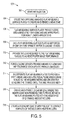
- FIG. 5 illustrates a high-level flow chart showing the functionality of a linear fusing nip zone, in accordance with a preferred embodiment.
- FIG. 2 illustrated is a perspective view 200 of an image forming apparatus of a linear fusing nip zone, in accordance with a preferred embodiment.
- the tracking rollers 202 are placed in context with the linear air bearing surface plates 204.
- FIG. 3 illustrated is a block diagram 300 of a linear fusing nip zone, in accordance with a preferred embodiment.
- This system paper enters 310 into an image forming apparatus with the help of an entrance roller 312.
- the entrance roller 312 is configured and set with two opposing unheated flat air bearing surface plates 204 for creating an extended linear zone.
- the flat air bearing surface plates provide a zero media-bend zone for fusing.
- Each flat air bearing surface plate is supported by one or more springs, or force loading devices 316, thereby providing the load required for achieving proper image performance when an image is being processed.
- the belt placement unit 304 includes two independent non-permeable belts for creating the fusing nip zone.
- the belts are controlled by belt tracking motion 306 and belt tensioning motion 308.
- the heater rollers 302 and a tracking roller 202 are shown in contact with the belts for heating and running the belt when printing is being done.
- the heater rollers 302 are ideally positioned to directly heat the surface of the side of the belt that comes into contact with paper during linear fusing nip zone operation.
- heat rollers 302 are shown, it should be appreciated that the rollers do not need to be heated and that another heat source, such as a heat lamp, could be used to heat the surface of the belts that comes into direct contact with the medium (paper).
- the exit roller 318 acts as an output interface through which the printed paper is sent out of the image forming apparatus of a linear fusing nip zone.
- FIG. 4 illustrated is a sectional view of a nipping mechanism 400 using two opposing sections.
- the design encircled by the dashed line 404 is located below a mirror image of components that make of the upper section of the nipping mechanism.
- flat air bearing surface plates 204 create part of a linear nip of a linear fusing nip zone.
- a nipping mechanism 400 uses two opposing unheated flat linear air bearing surface plates 204 to create an extended linear zone wherein two independent non-permeable belts 301 travel between thereby creating the fusing nip zone.
- the belts 301 are controlled by belt tracking motion control 306 and by belt tensioning motion control 308 over tracking rollers 202.
- the heater rollers 302 and tracking rollers 202 are set for running the belts 301 when printing is being done in an image forming zone created between the outside surface of belts 301 within the linear fusing nip zone.
- paper 310 can enter into the processing unit with the help of the belts 301 and entrance rollers 312.
- the entrance rollers 312 are further configured and set with two opposing unheated flat air bearing surface plates 204 and thereby create an extended linear zone.
- the loading operation in the image forming apparatus of a linear fusing nip zone moves in tandem to enable jam clearance 402 in-between the entrance rollers 312 and the linear flat air bearing surface plates 204.
- Flat air bearing surface plates 204 provide a zero media-bend zone for fusing. These flat air bearing surface plates 204 are appropriate for highly loaded applications. Each flat air bearings plate 204 can be supported by one or more springs, or force-loading devices, thereby providing the load required for achieving proper media handling and performance through the system 400.
- the force-loading device provided by the combination of rollers and belts 301 provide a means for removing any tolerance stack-ups and parallelism issues in an image forming apparatus of a linear fusing nip zone.
- the exit rollers 318 act as an output interface through which the printed paper is sent out of the image forming apparatus of the linear fusing nip zone.
- Fusing of images onto paper can be more effective using the embodiment shown in FIG. 4 because the belts 301 are heated directly on their outer surface by a heat source such as the heater rollers 302, before the belts 301 come into direct contact with paper within the fusing nip zone.
- a heat source such as the heater rollers 302
- Other heat source can be used to accomplish heating of the outer surface of belts 30, such as a heat lamp and other heat source known in the art.
- Heated rollers are ideal because less heat is generated within the system housing by direct contact with heated rollers as opposed to a radiating heat source.
- heat is generated on the belt using a heat source located opposite the contract surface of the belts 301. Heat applied to the backside of a belt, opposite the contacting surface of the belt, relies on heat transfer to warm the contact surface, which is a less efficient way to heat a belt and also results in unwanted heat generation within the overall system compartment or housing.
- FIG. 5 illustrates a high-level flow chart 500 showing the functionality of a linear fusing nip zone, in accordance with a preferred embodiment.
- initialization can occur.
- two opposing unheated flat air bearing surface plates are utilized to create an extended linear zone.
- Flat air bearing surface plates provide a zero media-bend zone for fusing and are appropriate for highly loaded applications as indicated in block 506.
- each flat air bearing surface plate is supported by one or more springs or force loading devices.
- the load required for achieving proper image performance is provided to the flat air bearing surface plates by the one or more springs or force loading devices as indicated in block 510.
- Force loading devices can also be used for providing a means for removing any tolerance stack ups and parallelism issues as depicted in block 512.
- Flat air bearing plates are incorporated in the system to provide a stiff, linear and a non-frictional plane which can be scaled to required widths and lengths for achieving the desired dwell time and process width as described in block 514.
- An extended linear nip zone is further created where two independent non permeable belts travel between the flat air bearing plates with the assistance of entrance rollers and exit rollers as indicated in block 516.
- a heated fusing nip zone is created by application of heat to contact surfaces of the belts with heater rollers as indicated in block 518.
Landscapes
- Physics & Mathematics (AREA)
- General Physics & Mathematics (AREA)
- Fixing For Electrophotography (AREA)
Abstract
Description
- Embodiments are generally related to image processing. Embodiments are also related to the field of nipping mechanisms. Embodiments are additionally related to linear fusing in nipping mechanisms.
- Processes and devices have been used for image processing in which a nipping mechanism can be applied to an image processing apparatus which is being represented by electro photographic copiers, laser printers or facsimile machines. A nipping mechanism is usually provided in a fixing device disposed downstream from a transfer belt for transporting a sheet having a toner image transferred through a photosensitive drum. A nipping mechanism comprises a fixing roller having a heater embedded therein, and a pressure roller disposed in opposed relation to the fixing roller while allowing the lower portion thereof to be in close contact with the fixing roller.
- In such an electrographic apparatus generally a fixing device in a two-roll system composed of a heating roll and a pressure roll, that is being kept in contact with each other, is employed passing through the recording medium over the surface. An unfixed toner image can be formed through the nip zone. A nip zone is formed when the recording medium is in contact with both rolls. Then the toner in the electrographic apparatus is molten by heat and pressure so that the toner image is fixed on the surface of the recording medium as a permanent image. As the case may be in place of the heating roll and pressure roll, the heating member of each has an endless belt shape.
- As xerographic imaging systems continue to increase in speed, the need to provide an adequate nip width to a fuser toner and then to a media also increases. Referring to FIG. 1, labeled as prior-art, a
graph 100 illustrates traditional roll pairs. The graph shows that traditional roll pairs are limited due to a relationship between roll diameters, elastomer thickness, and the available load. For example, to achieve a 30ms (milliseconds) dwell time when a 100ppm (pulse position modulation) rate is required, a nip width of 14.04mm (millimeters) is required. As speeds increase to 150ppm, an equivalent nip grows to 21.06m. At 200ppm the nip width is 28.08mm. In the graph the load (pounds) 102 defines the horizontal axis and dwell time (ms) 104 defines the vertical axis. The graph also shows the representations inspecific values 106 when plotted. - Hence there is a need to provide an adequate nip width to a fuser toner by using a nipping mechanism. As xerographic imaging systems continue to increase in speed, a nipping mechanism with fusing enhancement that can be used in image processing for providing improved performance is needed. Ideally the sheet nipping mechanism and nipping mechanism for fixing devices can be enhanced by using a method of linear fusing in nipping mechanism.
- The following summary is provided to facilitate an understanding of some of the innovative features unique to the embodiments disclosed and is not intended to be a full description. A full appreciation of the various aspects of the embodiments can be gained by taking the entire specification, claims, drawings, and abstract as a whole.
- It is, therefore, one aspect of the present invention to provide for an improved image forming apparatus.
- It is another aspect of the present invention to provide for an improved nipping mechanism.
- It is a further aspect of the present invention to provide for an improved image performance by providing a fusing nip mechanism.
- It is a further aspect of the present invention to provide for an improved image performance by providing a fusing nip mechanism.
- The aforementioned aspects and other objectives and advantages can now be achieved as described herein. An image forming apparatus defined by two flat, linear surface plates and two belts independently routed outside one of the two flat linear surface plates using a combination of rollers providing a stiff, linear, no-friction plane scalable in dimension to form the linear nip zone. The linear nip zone is further defined having and entrance defined by entrance rollers operating within each of the two belts and an exit defined by exit rollers operating within each of the two belts. Force loading devices associated with each of the two flat linear surface plates provide a load required for the two flat linear surface plates to enable the linear nip zone to achieve proper image performance. At least one heater source (e.g., a heat roller) can be associated with each of the two belts for providing heat onto surfaces of the two belts that will directly contact paper processed through the linear nip zone.
In a further embodiment the image forming apparatus further comprises at least one heat source associated with each of said two belts, said at least one heat source providing heat directly to a surface said two belts that will directly contact paper processed through the linear nip zone.
In a further embodiment the image forming apparatus further comprises force loading devices associated with each of said two flat linear surface plates, said force loading devices providing a load required for said two flat linear surface plates to enable the linear nip zone to achieve proper image performance.
In a further embodiment said linear nip zone is further defined by having and entrance defined by entrance rollers operating within each of said two belts and an exit defined by exit rollers operating within each of said two belts.
In one embodiment of the image forming apparatus of claim 9, the apparatus further comprises force loading devices associated with each of said two unheated flat linear air bearing surface plates, said force loading devices providing a load required for said plates to enable the nip zone to achieve proper image performance.
In a further embodiment the image forming apparatus further comprises at least one heater roller associated with each of said two independent non-permeable belts, said at least one heater roller providing heat directly to a surface said two independent non-permeable belts that will directly contact paper processed through the nip zone.
In a further embodiment the image forming apparatus further comprises force loading devices associated with each of said two unheated flat linear air bearing surface plates, said force loading devices providing a load required for said plates to enable the nip zone to achieve proper image performance.
In a further embodiment the image forming apparatus further comprises at least one heater roller associated with each of said two independent non-permeable belts, said at least one heater roller providing heat directly to a surface said two independent non-permeable belts that will directly contact paper processed through the nip zone.
In one embodiment of the method of claim 10 the two independent belts are non-permeable belts.
In a further embodiment heat is applied to the external, contact surface of the two independent belts with heater rollers.
In a further embodiment heat is applied to the external, contact surface of the two independent non-permeable belts with heater rollers. - The accompanying figures, in which like reference numerals refer to identical or functionally-similar elements throughout the separate views and which are incorporated in and form a part of the specification, further illustrate the embodiments and, together with the detailed description, serve to explain the embodiments disclosed herein.
- FIG. 1, labeled "prior art", illustrates a graph representation showing traditional roll pairs with reference to load and dwell time used for nipping mechanisms.
- FIG. 2 illustrates a perspective view of an image forming apparatus of a linear fusing nip zone, in accordance with a preferred embodiment.
- FIG. 3 illustrates a block diagram of a linear fusing nip zone, in accordance with a
- FIG. 4 illustrates a sectional view with the usage of two opposing flat air bearings to create a linear nip of a linear fusing nip zone, in accordance with a preferred embodiment.
- FIG. 5 illustrates a high-level flow chart showing the functionality of a linear fusing nip zone, in accordance with a preferred embodiment.
- The particular values and configurations discussed in these non-limiting examples can be varied and are cited merely to illustrate at least one embodiment and are not intended to limit the scope thereof.
- Referring to FIG. 2, illustrated is a
perspective view 200 of an image forming apparatus of a linear fusing nip zone, in accordance with a preferred embodiment. Thetracking rollers 202 are placed in context with the linear air bearingsurface plates 204. - Referring to FIG. 3, illustrated is a block diagram 300 of a linear fusing nip zone, in accordance with a preferred embodiment. In this system paper enters 310 into an image forming apparatus with the help of an
entrance roller 312. Theentrance roller 312 is configured and set with two opposing unheated flat air bearingsurface plates 204 for creating an extended linear zone. The flat air bearing surface plates provide a zero media-bend zone for fusing. Each flat air bearing surface plate is supported by one or more springs, orforce loading devices 316, thereby providing the load required for achieving proper image performance when an image is being processed. Thebelt placement unit 304 includes two independent non-permeable belts for creating the fusing nip zone. The belts are controlled bybelt tracking motion 306 andbelt tensioning motion 308. Theheater rollers 302 and atracking roller 202 are shown in contact with the belts for heating and running the belt when printing is being done. Theheater rollers 302 are ideally positioned to directly heat the surface of the side of the belt that comes into contact with paper during linear fusing nip zone operation. Althoughheat rollers 302 are shown, it should be appreciated that the rollers do not need to be heated and that another heat source, such as a heat lamp, could be used to heat the surface of the belts that comes into direct contact with the medium (paper). Theexit roller 318 acts as an output interface through which the printed paper is sent out of the image forming apparatus of a linear fusing nip zone. - Referring to FIG. 4, illustrated is a sectional view of a
nipping mechanism 400 using two opposing sections. The design encircled by the dashedline 404 is located below a mirror image of components that make of the upper section of the nipping mechanism. In accordance with the embodiment, flat air bearingsurface plates 204 create part of a linear nip of a linear fusing nip zone. Anipping mechanism 400 uses two opposing unheated flat linear air bearingsurface plates 204 to create an extended linear zone wherein twoindependent non-permeable belts 301 travel between thereby creating the fusing nip zone. Thebelts 301 are controlled by belt trackingmotion control 306 and by belttensioning motion control 308 over trackingrollers 202. Theheater rollers 302 and trackingrollers 202 are set for running thebelts 301 when printing is being done in an image forming zone created between the outside surface ofbelts 301 within the linear fusing nip zone. During operation,paper 310 can enter into the processing unit with the help of thebelts 301 andentrance rollers 312. Theentrance rollers 312 are further configured and set with two opposing unheated flat air bearingsurface plates 204 and thereby create an extended linear zone. The loading operation in the image forming apparatus of a linear fusing nip zone moves in tandem to enablejam clearance 402 in-between theentrance rollers 312 and the linear flat air bearingsurface plates 204. - Flat air bearing
surface plates 204 provide a zero media-bend zone for fusing. These flat air bearingsurface plates 204 are appropriate for highly loaded applications. Each flatair bearings plate 204 can be supported by one or more springs, or force-loading devices, thereby providing the load required for achieving proper media handling and performance through thesystem 400. The force-loading device provided by the combination of rollers andbelts 301 provide a means for removing any tolerance stack-ups and parallelism issues in an image forming apparatus of a linear fusing nip zone. Theexit rollers 318 act as an output interface through which the printed paper is sent out of the image forming apparatus of the linear fusing nip zone. - Fusing of images onto paper can be more effective using the embodiment shown in FIG. 4 because the
belts 301 are heated directly on their outer surface by a heat source such as theheater rollers 302, before thebelts 301 come into direct contact with paper within the fusing nip zone. Other heat source can be used to accomplish heating of the outer surface ofbelts 30, such as a heat lamp and other heat source known in the art. Heated rollers, however, are ideal because less heat is generated within the system housing by direct contact with heated rollers as opposed to a radiating heat source. In prior art devices, heat is generated on the belt using a heat source located opposite the contract surface of thebelts 301. Heat applied to the backside of a belt, opposite the contacting surface of the belt, relies on heat transfer to warm the contact surface, which is a less efficient way to heat a belt and also results in unwanted heat generation within the overall system compartment or housing. - Referring to FIG. 5, illustrates a high-
level flow chart 500 showing the functionality of a linear fusing nip zone, in accordance with a preferred embodiment. As depicted atblock 502, initialization can occur. Next, as indicated inblock 504, two opposing unheated flat air bearing surface plates are utilized to create an extended linear zone. Flat air bearing surface plates provide a zero media-bend zone for fusing and are appropriate for highly loaded applications as indicated inblock 506. Thereafter as described inblock 508, each flat air bearing surface plate is supported by one or more springs or force loading devices. The load required for achieving proper image performance is provided to the flat air bearing surface plates by the one or more springs or force loading devices as indicated inblock 510. Force loading devices can also be used for providing a means for removing any tolerance stack ups and parallelism issues as depicted inblock 512. Flat air bearing plates are incorporated in the system to provide a stiff, linear and a non-frictional plane which can be scaled to required widths and lengths for achieving the desired dwell time and process width as described inblock 514. An extended linear nip zone is further created where two independent non permeable belts travel between the flat air bearing plates with the assistance of entrance rollers and exit rollers as indicated inblock 516. Finally, a heated fusing nip zone is created by application of heat to contact surfaces of the belts with heater rollers as indicated inblock 518.
Claims (10)
- An image forming apparatus, comprising:two flat, linear surface plates; andtwo belts independently routed outside one of said two flat linear surface plates using a combination of rollers;wherein said two belts and said flat linear surface plates surrounded by said two belts provide a stiff, linear, no-friction plane scalable in dimension to form a linear nip zone.
- The image forming apparatus of claim 1, wherein said linear nip zone is further defined by having and entrance defined by entrance rollers operating within each of said two belts and an exit defined by exit rollers operating within each of said two belts.
- The image forming apparatus of claim 2, further comprising force loading devices associated with each of said two flat linear surface plates, said force loading devices providing a load required for said two flat linear surface plates to enable the linear nip zone to achieve proper image performance.
- The image forming apparatus of claim 3, further comprising at least one heat source associated with each of said two belts, said at least one heat source providing heat directly to a surface said two belts that will directly contact paper processed through the linear nip zone.
- The image forming apparatus of claim 4 wherein said two felts are non-permeable belts.
- The image forming apparatus of claim 1, further comprising force loading devices associated with each of said two flat linear surface plates, said force loading devices providing a load required for said two flat linear surface plates to enable the linear nip zone to achieve proper image performance.
- The image forming apparatus of claim 6, wherein said linear nip zone is further defined by having and entrance defined by entrance rollers operating within each of said two belts and an exit defined by exit rollers operating within each of said two belts.
- The image forming apparatus of claim 7, further comprising at least one heat source associated with each of said two belts, said at least one heat source providing heat directly to a surface said two belts that will directly contact paper processed through the linear nip zone.
- An image forming apparatus comprising:two unheated flat linear air bearing surface plates providing a stiff, linear, no-friction plane that is scalable to a specified width and length for achieving a desired dwell time and process width as part of forming a linear nip zone; andtwo independent non-permeable belts, each routed outside of one of the two unheated flat linear air bearing surface plates using a combination of rollers, said two unheated flat linear air bearing surface plates, two independent non-permeable belts defining a nip zone having and entrance defined by entrance rollers operating with each of said two independent non-permeable belts and an exit defined by exit rollers operating within each of said two independent non-permeable belts.
- A method for providing a nipping mechanism, comprising:providing two opposing unheated flat air bearing surface plates to create an extended linear zone;supporting each unheated flat air bearing surface plate with force loading devices, wherein loads required for achieving proper image performance is provided to the flat air bearing surface plates by the force loading devices;creating an extended linear nip zone by providing two independent belts configured to travel between the flat air bearing plates with the assistance of rollers including entrance rollers and exit rollers associated with each of said two independent belts;creating a heated fusing nip zone by applying heat to external, contact surfaces of the two independent belts.
Applications Claiming Priority (1)
| Application Number | Priority Date | Filing Date | Title |
|---|---|---|---|
| US11/523,263 US7471923B2 (en) | 2006-09-18 | 2006-09-18 | Linear fusing nip zone |
Publications (2)
| Publication Number | Publication Date |
|---|---|
| EP1901137A1 true EP1901137A1 (en) | 2008-03-19 |
| EP1901137B1 EP1901137B1 (en) | 2014-01-15 |
Family
ID=38996642
Family Applications (1)
| Application Number | Title | Priority Date | Filing Date |
|---|---|---|---|
| EP07116662.3A Not-in-force EP1901137B1 (en) | 2006-09-18 | 2007-09-18 | Linear fusing nip zone |
Country Status (3)
| Country | Link |
|---|---|
| US (1) | US7471923B2 (en) |
| EP (1) | EP1901137B1 (en) |
| JP (1) | JP2008077081A (en) |
Families Citing this family (2)
| Publication number | Priority date | Publication date | Assignee | Title |
|---|---|---|---|---|
| US7947420B2 (en) * | 2007-02-26 | 2011-05-24 | Konica Minolta Business Technologies, Inc. | Image forming method |
| KR101831787B1 (en) * | 2012-09-11 | 2018-02-23 | 에스프린팅솔루션 주식회사 | fusing device and fusing method |
Citations (5)
| Publication number | Priority date | Publication date | Assignee | Title |
|---|---|---|---|---|
| US5319429A (en) * | 1991-11-20 | 1994-06-07 | Konica Corporation | Color image forming apparatus using fixing apparatus for glossy images |
| US6226474B1 (en) * | 1999-12-16 | 2001-05-01 | Nexpress Solutions Llc | Air impingement post fuser receiver member cooler device |
| JP2004117518A (en) | 2002-09-24 | 2004-04-15 | Canon Inc | Heat fixing device and image forming apparatus having the same |
| US20060127142A1 (en) * | 2004-12-13 | 2006-06-15 | Canon Kabushiki Kaisha | Image heating device |
| JP2006178119A (en) | 2004-12-21 | 2006-07-06 | Samsung Yokohama Research Institute Co Ltd | Fixing apparatus and image forming apparatus |
Family Cites Families (12)
| Publication number | Priority date | Publication date | Assignee | Title |
|---|---|---|---|---|
| US4242566A (en) * | 1980-03-21 | 1980-12-30 | Pitney Bowes Inc. | Heat-pressure fusing device |
| JP2000330407A (en) * | 1999-05-24 | 2000-11-30 | Hitachi Ltd | Fixing device |
| JP3993983B2 (en) * | 2001-01-24 | 2007-10-17 | 株式会社リコー | Fixing apparatus and image forming apparatus |
| US6795677B2 (en) * | 2002-09-16 | 2004-09-21 | Xerox Corporation | High speed heat and pressure belt fuser |
| JP4179867B2 (en) * | 2002-12-24 | 2008-11-12 | 株式会社リコー | Fixing apparatus and image forming apparatus |
| JP2004234951A (en) * | 2003-01-29 | 2004-08-19 | Canon Inc | Heating equipment |
| JP4396962B2 (en) * | 2003-03-18 | 2010-01-13 | 株式会社リコー | Fixing device and image forming apparatus having the fixing device |
| US7283759B2 (en) * | 2004-03-31 | 2007-10-16 | Canon Kabushiki Kaisha | Image forming apparatus with heating member control in accordance with type of recording material |
| JP2006030248A (en) * | 2004-07-12 | 2006-02-02 | Ricoh Co Ltd | Toner, fixing device, image forming apparatus |
| JP2006194930A (en) * | 2005-01-11 | 2006-07-27 | Konica Minolta Business Technologies Inc | Fixing apparatus |
| JP2006243471A (en) * | 2005-03-04 | 2006-09-14 | Fuji Xerox Co Ltd | Fixing device and image forming apparatus |
| US7200354B2 (en) * | 2005-06-21 | 2007-04-03 | Canon Kabushiki Kaisha | Image heating apparatus |
-
2006
- 2006-09-18 US US11/523,263 patent/US7471923B2/en not_active Expired - Fee Related
-
2007
- 2007-09-11 JP JP2007234888A patent/JP2008077081A/en active Pending
- 2007-09-18 EP EP07116662.3A patent/EP1901137B1/en not_active Not-in-force
Patent Citations (5)
| Publication number | Priority date | Publication date | Assignee | Title |
|---|---|---|---|---|
| US5319429A (en) * | 1991-11-20 | 1994-06-07 | Konica Corporation | Color image forming apparatus using fixing apparatus for glossy images |
| US6226474B1 (en) * | 1999-12-16 | 2001-05-01 | Nexpress Solutions Llc | Air impingement post fuser receiver member cooler device |
| JP2004117518A (en) | 2002-09-24 | 2004-04-15 | Canon Inc | Heat fixing device and image forming apparatus having the same |
| US20060127142A1 (en) * | 2004-12-13 | 2006-06-15 | Canon Kabushiki Kaisha | Image heating device |
| JP2006178119A (en) | 2004-12-21 | 2006-07-06 | Samsung Yokohama Research Institute Co Ltd | Fixing apparatus and image forming apparatus |
Also Published As
| Publication number | Publication date |
|---|---|
| EP1901137B1 (en) | 2014-01-15 |
| JP2008077081A (en) | 2008-04-03 |
| US20080124145A1 (en) | 2008-05-29 |
| US7471923B2 (en) | 2008-12-30 |
Similar Documents
| Publication | Publication Date | Title |
|---|---|---|
| US8417169B2 (en) | Fixing device and image forming apparatus incorporating same | |
| US7177579B2 (en) | Image heating apparatus | |
| JP5133370B2 (en) | Fixing device and printing device | |
| JP5034874B2 (en) | Fixing device | |
| CN108333898B (en) | Image heating apparatus | |
| EP1901137B1 (en) | Linear fusing nip zone | |
| JP2008216850A (en) | Fixing device and image forming apparatus | |
| JP5959909B2 (en) | Image heating device | |
| JPH08234602A (en) | Fixing device and image forming apparatus | |
| JP6668765B2 (en) | Fixing device and image forming device | |
| US11156947B2 (en) | Fixing device and image forming apparatus | |
| JP7243214B2 (en) | image forming device | |
| JP6797998B2 (en) | Image heating device | |
| JP2005257968A (en) | Fixing device and image forming apparatus | |
| JP2007079037A (en) | Image heating device | |
| JPH06348156A (en) | Heating device | |
| JP2010008684A (en) | Fixing device and image forming apparatus | |
| JP7210893B2 (en) | Fixing device and image forming apparatus provided with same | |
| JP2026002117A (en) | Fixing device and image forming apparatus | |
| JP6573393B2 (en) | Image forming apparatus | |
| JPH08305189A (en) | Heating device and image forming apparatus | |
| JP2024125873A (en) | Sheet conveying device and image forming apparatus | |
| JP2024070828A (en) | Fixing device and image forming apparatus | |
| JP2001146345A (en) | Printing equipment | |
| JP2023154440A (en) | Fixing device |
Legal Events
| Date | Code | Title | Description |
|---|---|---|---|
| PUAI | Public reference made under article 153(3) epc to a published international application that has entered the european phase |
Free format text: ORIGINAL CODE: 0009012 |
|
| AK | Designated contracting states |
Kind code of ref document: A1 Designated state(s): AT BE BG CH CY CZ DE DK EE ES FI FR GB GR HU IE IS IT LI LT LU LV MC MT NL PL PT RO SE SI SK TR |
|
| AX | Request for extension of the european patent |
Extension state: AL BA HR MK YU |
|
| 17P | Request for examination filed |
Effective date: 20080919 |
|
| 17Q | First examination report despatched |
Effective date: 20081023 |
|
| AKX | Designation fees paid |
Designated state(s): DE FR GB |
|
| GRAP | Despatch of communication of intention to grant a patent |
Free format text: ORIGINAL CODE: EPIDOSNIGR1 |
|
| INTG | Intention to grant announced |
Effective date: 20130906 |
|
| GRAS | Grant fee paid |
Free format text: ORIGINAL CODE: EPIDOSNIGR3 |
|
| GRAA | (expected) grant |
Free format text: ORIGINAL CODE: 0009210 |
|
| AK | Designated contracting states |
Kind code of ref document: B1 Designated state(s): DE FR GB |
|
| REG | Reference to a national code |
Ref country code: GB Ref legal event code: FG4D |
|
| REG | Reference to a national code |
Ref country code: DE Ref legal event code: R096 Ref document number: 602007034766 Country of ref document: DE Effective date: 20140220 |
|
| REG | Reference to a national code |
Ref country code: DE Ref legal event code: R097 Ref document number: 602007034766 Country of ref document: DE |
|
| PLBE | No opposition filed within time limit |
Free format text: ORIGINAL CODE: 0009261 |
|
| STAA | Information on the status of an ep patent application or granted ep patent |
Free format text: STATUS: NO OPPOSITION FILED WITHIN TIME LIMIT |
|
| 26N | No opposition filed |
Effective date: 20141016 |
|
| REG | Reference to a national code |
Ref country code: DE Ref legal event code: R097 Ref document number: 602007034766 Country of ref document: DE Effective date: 20141016 |
|
| REG | Reference to a national code |
Ref country code: FR Ref legal event code: PLFP Year of fee payment: 9 |
|
| PGFP | Annual fee paid to national office [announced via postgrant information from national office to epo] |
Ref country code: GB Payment date: 20150825 Year of fee payment: 9 Ref country code: DE Payment date: 20150820 Year of fee payment: 9 |
|
| PGFP | Annual fee paid to national office [announced via postgrant information from national office to epo] |
Ref country code: FR Payment date: 20150824 Year of fee payment: 9 |
|
| REG | Reference to a national code |
Ref country code: DE Ref legal event code: R119 Ref document number: 602007034766 Country of ref document: DE |
|
| GBPC | Gb: european patent ceased through non-payment of renewal fee |
Effective date: 20160918 |
|
| REG | Reference to a national code |
Ref country code: FR Ref legal event code: ST Effective date: 20170531 |
|
| PG25 | Lapsed in a contracting state [announced via postgrant information from national office to epo] |
Ref country code: GB Free format text: LAPSE BECAUSE OF NON-PAYMENT OF DUE FEES Effective date: 20160918 Ref country code: DE Free format text: LAPSE BECAUSE OF NON-PAYMENT OF DUE FEES Effective date: 20170401 Ref country code: FR Free format text: LAPSE BECAUSE OF NON-PAYMENT OF DUE FEES Effective date: 20160930 |