EP1901108A1 - Eye-use lens - Google Patents
Eye-use lens Download PDFInfo
- Publication number
- EP1901108A1 EP1901108A1 EP06756805A EP06756805A EP1901108A1 EP 1901108 A1 EP1901108 A1 EP 1901108A1 EP 06756805 A EP06756805 A EP 06756805A EP 06756805 A EP06756805 A EP 06756805A EP 1901108 A1 EP1901108 A1 EP 1901108A1
- Authority
- EP
- European Patent Office
- Prior art keywords
- lens
- optical region
- power
- lens optical
- distance
- Prior art date
- Legal status (The legal status is an assumption and is not a legal conclusion. Google has not performed a legal analysis and makes no representation as to the accuracy of the status listed.)
- Granted
Links
Images




Classifications
-
- G—PHYSICS
- G02—OPTICS
- G02C—SPECTACLES; SUNGLASSES OR GOGGLES INSOFAR AS THEY HAVE THE SAME FEATURES AS SPECTACLES; CONTACT LENSES
- G02C7/00—Optical parts
- G02C7/02—Lenses; Lens systems ; Methods of designing lenses
- G02C7/04—Contact lenses for the eyes
- G02C7/041—Contact lenses for the eyes bifocal; multifocal
- G02C7/043—Translating type
-
- G—PHYSICS
- G02—OPTICS
- G02C—SPECTACLES; SUNGLASSES OR GOGGLES INSOFAR AS THEY HAVE THE SAME FEATURES AS SPECTACLES; CONTACT LENSES
- G02C7/00—Optical parts
- G02C7/02—Lenses; Lens systems ; Methods of designing lenses
- G02C7/04—Contact lenses for the eyes
- G02C7/048—Means for stabilising the orientation of lenses in the eye
Definitions
- the present invention relates to an ocular lens, and particularly relates to an ocular lens suitable for use as a progressive multifocal far and near contact lens.
- a simultaneous perception type far and near contact lens 100 is known, in which a distance portion 102 for aiding far vision is disposed in the center portion of a lens optical region 101, a near portion 103 for aiding near vision is disposed in the peripheral part of the lens optical region 101, and an intermediate portion 104, in which a power gradually changes, is disposed between the distance portion 102 and the near portion 103 in the far and near contact lens, as shown in FIG. 12 , and the power in the lens optical region 101 is distributed in a concentric circle (Patent Document 1).
- a bifocal alternating-vision contact lens in which a distance portion is provided in the upper part of the lens optical region, and a near portion is provided in the lower part in the far and near contact lens, as described in Patent Document 2.
- a trifocal alternating-vision contact lens is also known in which a distance portion is provided in the upper part of the lens optical region, a near portion is provided in the lower part, and an intermediate portion is provided between the distance portion and the near portion in the far and near contact lens, as described in Patent Document 3.
- Patent Document 1 JP-A 59-208524
- Patent Document 2 US Patent No. 4693572 Specification
- Patent Document 3 UK Patent No. 1025677 Specification
- a power distribution is in an appearance of a concentric circle as shown in FIG. 12 in the far and near contact lens 100 described in Patent Document 1, and the far and near contact lens 100 therefore has no directionality, and is configured so as to function without hindrance even when the contact lens 100 rotates on the cornea of the eye, for example.
- the near portion 103 or the intermediate portion 104 of the contact lens 100 since the near portion 103 or the intermediate portion 104 of the contact lens 100 is positioned at the upper part of a pupil 110 of the eye during far vision, the light entering the pupil 110 through the near portion 103 or the intermediate portion 104 (particularly the near portion 103) may cause blurring or ghosting of the image, a clear image can not be obtained, and there is a risk of lowering contrast.
- an object of the present invention is to provide an ocular lens capable of securing a stable image in the distance portion and the near portion and capable of obtaining a clear image by suppressing blurring, ghosting, and the like of the image.
- a first aspect of the present invention provides a progressive multifocal ocular lens having a distance portion for aiding far vision, an intermediate portion for aiding intermediate vision, and a near portion for aiding near vision in a lens optical region, wherein the distance portion, the intermediate portion, and the near portion are sequentially arranged from an upper end to a lower end of an optical part from one end to the other end along a prescribed direction of the lens optical region, and power in these regions changes continuously.
- a power distribution of the lens optical region is set in accordance with the following formula (1) :
- PowerDist P - Power + ( Max - Add ⁇ ) tan - 1 ( Wave Bnf ⁇ X - Wave ) + tan - 1 Wave wherein each symbol in the formula (1) is defined as follows:
- ranges of values of the P-Power, the Max-Add, the Bnf, and the Wave are as follows: - 25 ⁇ D ⁇ P - Power ⁇ + 25 ⁇ D ; ⁇ 0 ⁇ D ⁇ Max - Add ⁇ + 8 ⁇ D ; 0.5 mm ⁇ Bnf ⁇ 7 mm ; and 1 ⁇ Wave ⁇ 8.
- the power distribution of the lens optical region is set by changing a radius of curvature of at least one of a front surface and a back surface of the lens optical region in a range from the distance portion to the near portion through the intermediate portion.
- the prescribed direction is a vertical direction of an eye during wearing the ocular lens.
- the prescribed direction is set so as to tilt towards the nose of the face from the vertical direction of the eye during wearing the ocular lens.
- the ocular lens is a contact lens having a rotation preventing mechanism at an end part in the prescribed direction, for preventing the lens from rotating.
- the rotation preventing mechanism is a prism ballast provided at the other end in the prescribed direction of the contact lens.
- the rotation preventing mechanism is a slab-off provided at one end part or both end parts in the prescribed direction of the contact lens.
- a power distribution in accordance with formula (1) is set in the prescribed direction of the lens optical region in at least one of the front surface and the back surface of the lens optical region, and an astigmatism degree is set in a direction orthogonal to the prescribed direction.
- a power distribution in accordance with the formula (1) is set in the prescribed direction of the lens optical region in at least one of the front surface and the back surface of the lens optical region, and the other of the front surface and back surface is formed to be a toric surface having an astigmatism correcting function.
- the ocular lens is a contact lens in which the back surface of the lens optical region is fitted on a cornea of an eye, and the back surface is formed to be a toric surface that is formed according to a shape of a cornea in an astigmatic state.
- the lens since all of the upper part of the lens is the distance portion, clearer far vision is possible than in a lens with the power distribution formed in a concentric circle, and image jumping or ghosting can be prevented by continuously changing the power of the lens.
- the power of an entire surface of the lens optical surface can be continuously changed without the occurrence of a mathematically non-continuous point, which aids in enhancing image quality and preventing image jumping.
- the power distribution in the lens optical region of the ocular lens can be specifically adapted to the ocular prescription of the ocular lens wearer. Consequently, power fluctuation in the distance portion and the near portion of the ocular lens can be minimized, and a stable image can therefore be maintained between the distance portion and the near portion.
- the power distribution along the prescribed direction of the lens optical region in the ocular lens is set in accordance with the formula (1), a fine power change corresponding to a movement of the ocular lens or the change of the visual line moving among the distance portion, the intermediate portion, and the near portion of the ocular lens, can be provided in the lens optical region.
- Image blurring and ghosting can therefore be suppressed to a minimum, lowering of contrast of the image can be prevented, and wavering or jumping of the image due to excessive power variation can be suppressed. As a result, a clear image can be secured.
- the prescribed direction of the lens optical region is set so as to be tilted towards the nose side of the face from the vertical direction of the eye during wearing the ocular lens. Since the distance portion, the intermediate portion, and the near portion are therefore arranged in the lens optical region so as to be tilted towards the nose side of the face in the lens optical region, thereby excellently responding to the characteristics of an eye that converges in the near vision.
- the ocular lens is a contact lens provided with a rotation preventing mechanism at an end portion side along the prescribed direction, rotation of the contact lens fitted on the cornea of the eye can be prevented or suppressed by the rotation preventing mechanism. Accordingly, a clear image can always be stably obtained in the distance portion and the near portion of the contact lens.
- the power distribution in accordance with the formula (1) is set along the prescribed direction of the lens optical region on at least one of the front surface and the back surface of the lens optical region, and the astigmatism degree is set in the direction orthogonal to the prescribed direction.
- the ocular lens can therefore be realized that is provided with a function of aiding the far vision and the near vision, as well as a function of correcting astigmatism.
- the power distribution in accordance with the formula (1) is set along the prescribed direction of the lens optical region on at least one of the front surface and the back surface of the lens optical region, and the other one of the front surface and back surface is formed in a toric surface having an astigmatism correcting function.
- the toric surface can therefore perform the astigmatism correcting function independently of the diopter distribution that follows the formula (1). Accordingly, the toric surface can exhibit correcting function to almost all astigmatism, including inverted astigmatism, straight astigmatism, and oblique astigmatism, and the like.
- the ocular lens is a contact lens, with the back surface of the lens optical region fitted on the cornea of the eye, and the back surface is a toric surface formed corresponding to the shape of the cornea in the astigmatic state. Therefore, the astigmatism correcting function can be exhibited and also the rotation preventing function of the ocular lens (contact lens) can be exhibited by fitting the back surface on the cornea of the eye.
- the end portion side along the prescribed direction of the lens optical region in the ocular lens has the rotation preventing mechanism, prevention of the rotation of the ocular lens (contact lens) can be even more effectively realized.
- FIG. 1 is a front view showing a far and near contact lens according to Embodiment 1 of the ocular lens of the present invention.
- FIG. 2 is a sectional view taken along the line II-II in FIG. 1 .
- FIG. 5 is a graph showing a power distribution (when the distance portion shows a minus power) in the lens optical region of FIG. 3 .
- FIG. 6 is a graph showing the power distribution (when the distance portion shows a plus power) in the lens optical region of FIG. 3 .
- the far and near contact lens 10 shown in FIG. 1 is the ocular lens applied to an eye such as a presbyopic eye that deteriorates in a sight adjustment capability, for aiding the sight adjustment capability, and is a progressive multifocal contact lens in which a plurality of powers are progressively arranged within a lens optical region 11 in the center portion.
- the lens optical region 11 of the far and near contact lens 10 is provided with a distance portion 12 having a far vision power for aiding in the far vision, a near portion 13 having a near vision power for aiding in the near vision, and an intermediate portion 14 in which the power progressively changes between the distance portion 12 and the near portion 13.
- a flange part 15 for placing the far and near contact lens 10 on the cornea 2 (see also FIG. 9 ) of an eye 1 is provided on the periphery of the lens optical region 11 in the far and near contact lens 10.
- the reference numeral 3 in FIG. 9 indicates a pupil for taking in light
- 4 indicates the sclera
- 5 indicates the upper eyelid
- 6 indicates the lower eyelid.
- the distance portion 12, the intermediate portion 14, and the near portion 13 are sequentially arranged in the prescribed direction of the lens optical region 11, i.e., from an upper end point A as one end of the lens optical region 11 to a lower end point B as the other end of the lens optical region 11 along the direction of the vertical axis N of the lens optical region 11.
- the direction of the vertical axis N of the lens optical region 11 is the direction that coincides with the vertical direction (upper and lower direction) of the eye 1 when the far and near contact lens 10 is fitted on the eye 1.
- the power distribution of the lens optical region 11 changes right and left symmetrically along the direction of the vertical axis N of the lens optical region 11, i.e., the power is the same along the direction of the lateral axis M orthogonal to the vertical axis N.
- the power is set so as to increase from the distance portion 12 to the near portion 13 through the intermediate portion 14 arranged along the direction of the vertical axis N.
- the vertical axis N of the lens optical region 11 is a straight line passing through the center P of the lens optical region 11 from the upper end point A to the lower end point B.
- the power distribution along the direction of the vertical axis N in the lens optical region 11 is set in accordance with the following formula (1).
- PowerDist P - Power + ( Max - Add ⁇ ) tan - 1 ( Wave Bnf ⁇ X - Wave ) + tan - 1 Wave wherein each symbol in the formula (1) is defined as follows:
- a range of values of the P-Power, the Max-Add, the Bnf, and the Wave are as follows: - 25 ⁇ P - Power ⁇ + 25 ⁇ D ; ⁇ 0 ⁇ D ⁇ Max - Add ⁇ + 8 ⁇ D ; 0.5 mm ⁇ Bnf ⁇ 7 mm ; and 1 ⁇ Wave ⁇ 8.
- FIGS. 5 and 6 The power distribution along the direction of the vertical axis N of the lens optical region 11 set by the formula (1) is shown in FIGS. 5 and 6 .
- the vertical axis indicates the power (D)
- the horizontal axis indicates the distance X (mm) from the upper end point A of the lens optical region 11.
- FIG. 5 shows the case of a far and near contact lens 10 used for myopia in which the distance portion 12 shows a minus power
- FIG. 6 shows the case of a far and near contact lens 10 used for hyperopia in which the distance portion 12 shows a plus power.
- the power distribution of the lens optical region 11 of the far and near contact lens 10 is set from the prescription of the eye of the wearer of the far and near contact lens 10 by obtaining necessary far vision correcting power and near vision correcting power, defining P-Power, Max-Add, Bnf, and Wave from these correcting powers and the like, and substituting the values thus obtained into the formula (1).
- the power distribution along the direction of the vertical axis N in the lens optical region 11 of the far and near contact lens 10 is thus set according to formula (1), whereby a specific power distribution adapted to the prescription of the eye of a lens wearer can be realized, and a fine power variation in accordance with the movement of the far and near contact lens 10 or variation of the visual line moving among the distance portion 12, the intermediate portion 14, and the near portion 13 of the lens optical region 11, can be provided in the lens optical region 11 (particularly the boundary regions of the distance portion 12, the intermediate portion 14, and the near portion 13).
- the power distribution of the lens optical region 11 thus set is obtained by changing, i.e., sequentially shortening, the curvature radius R of at least one of the convex surface 16A ( FIG. 2 ) as the surface of the lens optical region 11 and the concave surface 16B ( FIG. 2 ) as the back surface in the range from the distance portion 12 to the near portion 13 through the intermediate portion 14.
- the concave surface 16B of the lens optical region 11 in a contact lens is formed in a spherical surface or an aspherical surface according to the shape of the cornea 2 of the lens wearer's eye 1, and the change of the abovementioned curvature radius R is therefore achieved with respect to the convex surface 16 of the lens optical region 11.
- the curvature radius R is set to the curvature radius Rh1 at the upper end point A, the same curvature radius Rh2 at point a, point b, and point c on the same lateral axis M, the same curvature radius Rh3 at point d, point e, and point f on the other same lateral axis M, the same curvature radius Rh4 at point g, point h, and point i on the other same lateral axis M, and the curvature radius Rh5 at the lower end point B.
- a prism ballast 17 as a rotation preventing mechanism is formed on the side of the lower end point B along the direction of the vertical axis N of the lens optical region 11.
- the prism ballast 17 is configured so that the portion on the side of the lower end point B of the lens optical region 11 is formed thick to function as a weight that prevents or suppresses rotation of the far and near contact lens 10 that is fitted on the cornea 2 of the eye 1, and always keeps the lower end point B of the lens optical region 11 positioned at a lower position.
- the presence of the prism ballast 17 ensures that the far and near contact lens 10 fitted on the cornea 2 of the eye 1 is always stably positioned with the distance portion 12 of the lens optical region 11 on the upper part of the eye 1, and the near portion 13 on the lower part of the eye 1.
- FIGS. 7 and 8 will be used to describe the manufacturing process for the far and near contact lens 10 whereby the aforementioned curvature radius R is formed in the convex surface 16A of the lens optical region 11, and the prism ballast 17 is formed on the side of the lower end point B of the lens optical region 11.
- a contact lens material 20 to be processed into a far and near contact lens 10 is held in a lens holder 21 and rotated around the rotation axis C, and while a cutting tool 22 is turned around an original point O, this cutting tool 22 approaches or turns against the direction of E with respect to the original point O, thereby changing a distance L between the cutting tool 22 and the original point O.
- a rotation angle ⁇ of the cutting tool 22 that turns from the position corresponding to the upper end point A of the near and far contact lens 10
- the cutting tool 22 is approached to the original point O.
- the convex surface 16A having the aforementioned curvature radius R is formed in the lens optical region 11, the prism ballast 17 is processed, and the far and near contact lens 10 is manufactured.
- the far and near contact lens 10 manufactured as described above is fitted on the cornea 2 of the eye 1, since the prism ballast 17 is provided in the far and near contact lens 10, the distance portion 12 of the lens optical region 11 is stably positioned on the upper part of the eye 1, and the near portion 13 is stably positioned on the lower part of the eye 1. Since most of the pupil 3 of the eye 1 therefore corresponds to the distance portion 12 of the far and near contact lens 10 in far vision, the pupil 3 can take in more light from the distance portion 12 of the far and near contact lens 10, and a clear far vision image can be obtained by the distance portion 12.
- FIG. 10 is a front view showing a modified example of the far and near contact lens shown in FIG. 1 .
- the same reference symbols are used to indicate components that are the same as those of the far and near contact lens 10 according to Embodiment 1, and description thereof is omitted.
- the prescribed direction of the lens optical region 11 in which the distance portion 12, the intermediate portion 14, and the near portion 13 are sequentially arranged is the direction of a tilted axis K that is tilted towards the nose of the face from the direction of the vertical axis N of the lens optical region 11, which coincides with the vertical direction (upper and lower direction) of the eye 1. Accordingly, the upper end point A and the lower end point B of the lens optical region 11 are set on the tilted axis K.
- the prism ballast 17 is also provided on the side of the lower end point BB on the vertical axis N in the lens optical region 11.
- the distance portion 12, the intermediate portion 14, and the near portion 13 are thus sequentially arranged along the tilted axis K that is tilted towards the nose from the vertical axis N of the lens optical region 11, so as to excellently respond to the characteristic of the eye that converges in the near vision.
- the pupil 3 can take in even more light that passes through the near portion 13 of the far and near contact lens 10, and a clear near-vision image can be ensured.
- the same advantages as the advantages of (1) to (4) of the aforementioned embodiments can be exhibited.
- FIG. 11 is a front view showing another modified example of the far and near contact lens shown in FIG. 1 .
- the same reference symbols are used to indicate components that are the same as those of the far and near contact lens 10 in Embodiment 1, and description thereof is omitted.
- the rotation preventing mechanism in the far and near contact lens 10 of the first embodiment is differentiated, and instead of using the prism ballast 17, slab-off parts 41 and 42 are formed, with both end parts in the flange part 15 along the direction of the vertical axis N cut away.
- slab-off parts 41, 42 are retained by the upper eyelid 5 and the lower eyelid 6, respectively, whereby the far and near contact lens 40 is prevented from rotating.
- the slab-off parts 41, 42 may also be formed in the end part of only one side of the flange part 15 in the far and near contact lens 40. Accordingly, in this modified example also, the same advantages of the advantages of (1) to (4) of the far and near contact lens 10 of the first embodiment can be exhibited.
- the power distribution in accordance with the formula (1) is set along the direction of the vertical axis N of the lens optical region 11 in at least one (usually the convex surface 16A) of the convex surface 16A and the concave surface 16B of the lens optical region 11 in the same manner as embodiment 1, and the astigmatism degree is also set in the same convex surface 16A or concave surface 16B (usually the convex surface 16A) as that on which this power distribution is set.
- the astigmatism degree is set along the direction of the lateral axis M orthogonal to the direction of the vertical axis N in which the power distribution according to the formula (1) is set.
- the function of aiding the far vision and the near vision by the distance portion 12 and the near portion 13 can be exhibited based on the power distribution set according to the formula (1), and in addition, the function of correcting the astigmatism (particularly such as inverted astigmatism and straight astigmatism) can be exhibited.
- the power distribution according to the formula (1) is set along the direction of the vertical axis N of the lens optical region 11 in at least one of the convex surface 16A and the concave surface 16B of the lens optical region 11 (usually the convex surface 16A), and the other one of the convex surface 16A and the concave surface 16B (usually the concave surface 16B) is formed to be the toric surface having the astigmatism correcting function.
- the toric surface is formed so as to correspond to the shape of the cornea 2 in an astigmatic state in the eye 1 of the lens wearer.
- the toric surface formed on the concave surface 16B in the lens optical region 11 of the far and near contact lens 10 is formed so as to have different curvature radius of two orthogonal axes corresponding to the shape of the cornea 2 in the astigmatic state.
- the power distribution according to the formula (1) is set along the direction of the vertical axis N of the lens optical region 11 in the convex surface 16A of the lens optical region 11, and the concave surface 16B is formed to be the toric surface having the astigmatism correcting function.
- the toric surface can therefore perform the astigmatism correcting function, irrespective of the power distribution according to the formula (1). Therefore, the toric surface of the concave surface 16B can exhibit the astigmatism correcting function to almost all astigmatism such as inverted astigmatism, straight astigmatism, and oblique astigmatism.
- the concave surface 16B is a toric surface formed according to the shape of the cornea 1 in the astigmatic state, the astigmatism correcting function can be exhibited by fitting this concave surface 16B on the cornea 2 of the eye 1 of the lens wearer, and the rotation preventing function of this far and near contact lens 10 can also be exhibited.
- the rotation preventing mechanism such as the prism ballast 17 or the slab-off parts 41 and 42 is provided on the end part side along the direction of the vertical axis N of the lens optical region 11 in the far and near contact lens 10
- prevention of the rotation of this far and near contact lens 10 can be further effectively realized, by a synergetic effect of the rotation preventing mechanism of the prism ballast 17 or the slab-off 41 and 42, and the rotation preventing function by the aforementioned toric surface.
- the present invention has been described above based on the embodiments, but the present invention is not limited thereto.
- the aforementioned first embodiment and both modified examples, the second embodiment and the third embodiment describe a case that the ocular lens is the contact lens.
- the present invention may provide a spectacle lens implanted into the eye, or the spectacle lens of a spectacle which is worn with spacing from the cornea 2.
Landscapes
- Health & Medical Sciences (AREA)
- Ophthalmology & Optometry (AREA)
- Physics & Mathematics (AREA)
- General Health & Medical Sciences (AREA)
- General Physics & Mathematics (AREA)
- Optics & Photonics (AREA)
- Eyeglasses (AREA)
Abstract
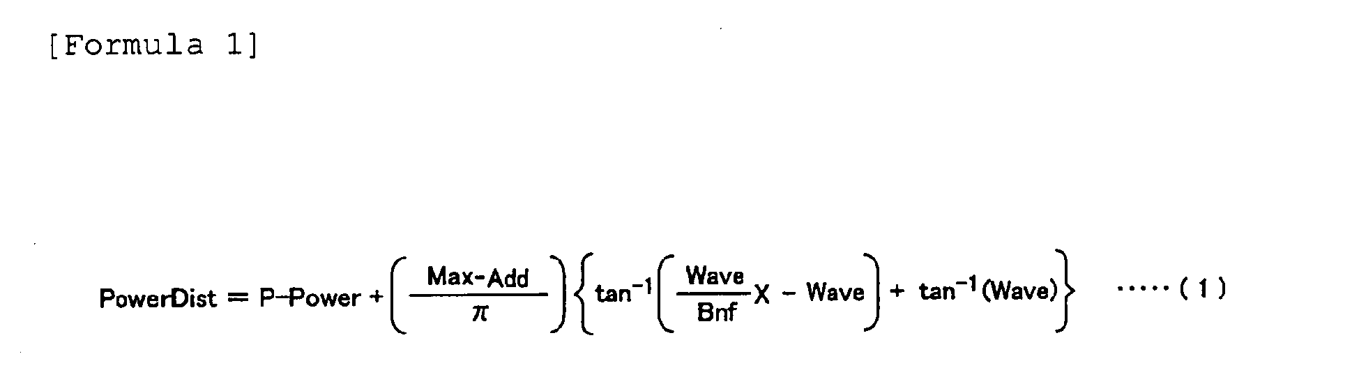
wherein each symbol in the formula (1) is defined as follows:
PowerDist: power distribution (unit: D (diopter));
P-Power: power (unit: D) at one end point of the lens optical region;
Max-Add: power difference (unit: D) between one end point and the other end point of the lens optical region;
Bnf: distance (unit: mm) from one end point of the lens optical region to a boundary between a distance power of the distance portion and a near power of the near portion;
Wave: power variation coefficient (wave degree); and
x: distance (unit: mm) from one end point of the lens optical region.
Description
- The present invention relates to an ocular lens, and particularly relates to an ocular lens suitable for use as a progressive multifocal far and near contact lens.
- A simultaneous perception type far and
near contact lens 100 is known, in which adistance portion 102 for aiding far vision is disposed in the center portion of a lensoptical region 101, anear portion 103 for aiding near vision is disposed in the peripheral part of the lensoptical region 101, and anintermediate portion 104, in which a power gradually changes, is disposed between thedistance portion 102 and thenear portion 103 in the far and near contact lens, as shown inFIG. 12 , and the power in the lensoptical region 101 is distributed in a concentric circle (Patent Document 1). - A bifocal alternating-vision contact lens is known, in which a distance portion is provided in the upper part of the lens optical region, and a near portion is provided in the lower part in the far and near contact lens, as described in
Patent Document 2. A trifocal alternating-vision contact lens is also known in which a distance portion is provided in the upper part of the lens optical region, a near portion is provided in the lower part, and an intermediate portion is provided between the distance portion and the near portion in the far and near contact lens, as described inPatent Document 3. - [Patent Document 1]
JP-A 59-208524
[Patent Document 2]
US Patent No. 4693572 Specification
[Patent Document 3]
UK Patent No. 1025677 - A power distribution is in an appearance of a concentric circle as shown in
FIG. 12 in the far andnear contact lens 100 described in Patent Document 1, and the far andnear contact lens 100 therefore has no directionality, and is configured so as to function without hindrance even when thecontact lens 100 rotates on the cornea of the eye, for example. However, in such a far andnear contact lens 100, since thenear portion 103 or theintermediate portion 104 of thecontact lens 100 is positioned at the upper part of apupil 110 of the eye during far vision, the light entering thepupil 110 through thenear portion 103 or the intermediate portion 104 (particularly the near portion 103) may cause blurring or ghosting of the image, a clear image can not be obtained, and there is a risk of lowering contrast. - In the bifocal or trifocal far and near contact lens described in
Patent Documents Patent Documents - In view of the above-described circumstances, the present invention is provided, and an object of the present invention is to provide an ocular lens capable of securing a stable image in the distance portion and the near portion and capable of obtaining a clear image by suppressing blurring, ghosting, and the like of the image.
- A first aspect of the present invention provides a progressive multifocal ocular lens having a distance portion for aiding far vision, an intermediate portion for aiding intermediate vision, and a near portion for aiding near vision in a lens optical region, wherein the distance portion, the intermediate portion, and the near portion are sequentially arranged from an upper end to a lower end of an optical part from one end to the other end along a prescribed direction of the lens optical region, and power in these regions changes continuously.
- In a second aspect of the present invention according to the first aspect, a power distribution of the lens optical region is set in accordance with the following formula (1) :

wherein each symbol in the formula (1) is defined as follows: - PowerDist: power distribution (unit: D (diopter));
- P-Power: power (unit: D) at one end point of the lens optical region;
- Max-Add: power difference (unit: D) between one end point and the other end point of the lens optical region;
- Bnf: distance (unit: mm) from one end point of the lens optical region to a boundary between a distance power of the distance portion and a near power of the near portion;
- Wave: power variation coefficient (wave degree); and
- x: distance (unit: mm) from one end point of the lens optical region.
- In a third aspect of the present invention according to the second aspect, ranges of values of the P-Power, the Max-Add, the Bnf, and the Wave are as follows:


and
- In a fourth aspect of the present invention according to the first, second, or third aspect, the power distribution of the lens optical region is set by changing a radius of curvature of at least one of a front surface and a back surface of the lens optical region in a range from the distance portion to the near portion through the intermediate portion.
- In a fifth aspect of the present invention according to any of the first through fourth aspects, the prescribed direction is a vertical direction of an eye during wearing the ocular lens.
- In a sixth aspect of the present invention according to any of the first through fourth aspects, the prescribed direction is set so as to tilt towards the nose of the face from the vertical direction of the eye during wearing the ocular lens.
- In a seventh aspect of the present invention according to any of the first through sixth aspects, the ocular lens is a contact lens having a rotation preventing mechanism at an end part in the prescribed direction, for preventing the lens from rotating.
- In an eighth aspect of the present invention according to the seventh aspect, the rotation preventing mechanism is a prism ballast provided at the other end in the prescribed direction of the contact lens.
- In a ninth aspect of the present invention according to the seventh aspect, the rotation preventing mechanism is a slab-off provided at one end part or both end parts in the prescribed direction of the contact lens.
- In a tenth aspect of the present invention according to any of the first through ninth aspects, a power distribution in accordance with formula (1) is set in the prescribed direction of the lens optical region in at least one of the front surface and the back surface of the lens optical region, and an astigmatism degree is set in a direction orthogonal to the prescribed direction.
- In an eleventh aspect of the present invention according to any of the first through ninth aspects, a power distribution in accordance with the formula (1) is set in the prescribed direction of the lens optical region in at least one of the front surface and the back surface of the lens optical region, and the other of the front surface and back surface is formed to be a toric surface having an astigmatism correcting function.
- In a twelfth aspect of the present invention according to the eleventh aspect, the ocular lens is a contact lens in which the back surface of the lens optical region is fitted on a cornea of an eye, and the back surface is formed to be a toric surface that is formed according to a shape of a cornea in an astigmatic state. ADVANTAGE OF THE INVENTION
- According to the first aspect of the present invention, since all of the upper part of the lens is the distance portion, clearer far vision is possible than in a lens with the power distribution formed in a concentric circle, and image jumping or ghosting can be prevented by continuously changing the power of the lens.
- According to the second aspect of the present invention, the power of an entire surface of the lens optical surface can be continuously changed without the occurrence of a mathematically non-continuous point, which aids in enhancing image quality and preventing image jumping.
- According to the second, third, fourth, or fifth aspect of the present invention, since the diopter distribution in the prescribed direction of the lens optical region in the ocular lens is set in accordance with the formula (1), the power distribution in the lens optical region of the ocular lens can be specifically adapted to the ocular prescription of the ocular lens wearer. Consequently, power fluctuation in the distance portion and the near portion of the ocular lens can be minimized, and a stable image can therefore be maintained between the distance portion and the near portion.
- Since the power distribution along the prescribed direction of the lens optical region in the ocular lens is set in accordance with the formula (1), a fine power change corresponding to a movement of the ocular lens or the change of the visual line moving among the distance portion, the intermediate portion, and the near portion of the ocular lens, can be provided in the lens optical region. Image blurring and ghosting can therefore be suppressed to a minimum, lowering of contrast of the image can be prevented, and wavering or jumping of the image due to excessive power variation can be suppressed. As a result, a clear image can be secured.
- According to the sixth aspect of the present invention, the prescribed direction of the lens optical region is set so as to be tilted towards the nose side of the face from the vertical direction of the eye during wearing the ocular lens. Since the distance portion, the intermediate portion, and the near portion are therefore arranged in the lens optical region so as to be tilted towards the nose side of the face in the lens optical region, thereby excellently responding to the characteristics of an eye that converges in the near vision.
- According to the seventh, eighth, or ninth aspect of the present invention, since the ocular lens is a contact lens provided with a rotation preventing mechanism at an end portion side along the prescribed direction, rotation of the contact lens fitted on the cornea of the eye can be prevented or suppressed by the rotation preventing mechanism. Accordingly, a clear image can always be stably obtained in the distance portion and the near portion of the contact lens.
- According to the tenth aspect of the present invention, the power distribution in accordance with the formula (1) is set along the prescribed direction of the lens optical region on at least one of the front surface and the back surface of the lens optical region, and the astigmatism degree is set in the direction orthogonal to the prescribed direction. The ocular lens can therefore be realized that is provided with a function of aiding the far vision and the near vision, as well as a function of correcting astigmatism.
- According to the eleventh aspect of the present invention, the power distribution in accordance with the formula (1) is set along the prescribed direction of the lens optical region on at least one of the front surface and the back surface of the lens optical region, and the other one of the front surface and back surface is formed in a toric surface having an astigmatism correcting function. The toric surface can therefore perform the astigmatism correcting function independently of the diopter distribution that follows the formula (1). Accordingly, the toric surface can exhibit correcting function to almost all astigmatism, including inverted astigmatism, straight astigmatism, and oblique astigmatism, and the like.
- According to the twelfth aspect of the present invention, the ocular lens is a contact lens, with the back surface of the lens optical region fitted on the cornea of the eye, and the back surface is a toric surface formed corresponding to the shape of the cornea in the astigmatic state. Therefore, the astigmatism correcting function can be exhibited and also the rotation preventing function of the ocular lens (contact lens) can be exhibited by fitting the back surface on the cornea of the eye. When the end portion side along the prescribed direction of the lens optical region in the ocular lens has the rotation preventing mechanism, prevention of the rotation of the ocular lens (contact lens) can be even more effectively realized.
- A best mode for carrying out the invention will be described hereinafter based on the drawings.
FIG. 1 is a front view showing a far and near contact lens according to Embodiment 1 of the ocular lens of the present invention.FIG. 2 is a sectional view taken along the line II-II inFIG. 1 .FIG. 5 is a graph showing a power distribution (when the distance portion shows a minus power) in the lens optical region ofFIG. 3 .FIG. 6 is a graph showing the power distribution (when the distance portion shows a plus power) in the lens optical region ofFIG. 3 . - The far and
near contact lens 10 shown inFIG. 1 is the ocular lens applied to an eye such as a presbyopic eye that deteriorates in a sight adjustment capability, for aiding the sight adjustment capability, and is a progressive multifocal contact lens in which a plurality of powers are progressively arranged within a lensoptical region 11 in the center portion. Namely, the lensoptical region 11 of the far andnear contact lens 10 is provided with adistance portion 12 having a far vision power for aiding in the far vision, anear portion 13 having a near vision power for aiding in the near vision, and anintermediate portion 14 in which the power progressively changes between thedistance portion 12 and thenear portion 13. Aflange part 15 for placing the far andnear contact lens 10 on the cornea 2 (see alsoFIG. 9 ) of an eye 1 is provided on the periphery of the lensoptical region 11 in the far andnear contact lens 10. - The
reference numeral 3 inFIG. 9 indicates a pupil for taking in light, 4 indicates the sclera, 5 indicates the upper eyelid, and 6 indicates the lower eyelid. - As shown in
FIGS. 1 and3 , thedistance portion 12, theintermediate portion 14, and thenear portion 13 are sequentially arranged in the prescribed direction of the lensoptical region 11, i.e., from an upper end point A as one end of the lensoptical region 11 to a lower end point B as the other end of the lensoptical region 11 along the direction of the vertical axis N of the lensoptical region 11. The direction of the vertical axis N of the lensoptical region 11 is the direction that coincides with the vertical direction (upper and lower direction) of the eye 1 when the far andnear contact lens 10 is fitted on the eye 1. At this time, the power distribution of the lensoptical region 11 changes right and left symmetrically along the direction of the vertical axis N of the lensoptical region 11, i.e., the power is the same along the direction of the lateral axis M orthogonal to the vertical axis N. However, the power is set so as to increase from thedistance portion 12 to thenear portion 13 through theintermediate portion 14 arranged along the direction of the vertical axis N. Here, the vertical axis N of the lensoptical region 11 is a straight line passing through the center P of the lensoptical region 11 from the upper end point A to the lower end point B. - Specifically, the power distribution along the direction of the vertical axis N in the lens
optical region 11 is set in accordance with the following formula (1).
wherein each symbol in the formula (1) is defined as follows: - PowerDist: power distribution (unit: D (diopter));
- P-Power: power (units: D) at the upper end point A of the lens
optical region 11; - Max-Add: power difference (unit: D) between the upper end point A and the lower end point B of the lens
optical region 11; - Bnf: distance (unit: mm) from the upper end point A of the lens
optical region 11 to a boundary between a distance vision power of thedistance portion 12 and a near vision power of thenear portion 13; - Wave: power variation coefficient (wave degree); and
- x: distance (unit: mm) from the upper end point A of the lens
optical region 11. - Here, a range of values of the P-Power, the Max-Add, the Bnf, and the Wave are as follows:


and
- The power distribution along the direction of the vertical axis N of the lens
optical region 11 set by the formula (1) is shown inFIGS. 5 and 6 . InFIGS. 5 and 6 , the vertical axis indicates the power (D), and the horizontal axis indicates the distance X (mm) from the upper end point A of the lensoptical region 11.FIG. 5 shows the case of a far andnear contact lens 10 used for myopia in which thedistance portion 12 shows a minus power, andFIG. 6 shows the case of a far andnear contact lens 10 used for hyperopia in which thedistance portion 12 shows a plus power. - The power distribution of the lens
optical region 11 of the far andnear contact lens 10 is set from the prescription of the eye of the wearer of the far andnear contact lens 10 by obtaining necessary far vision correcting power and near vision correcting power, defining P-Power, Max-Add, Bnf, and Wave from these correcting powers and the like, and substituting the values thus obtained into the formula (1). The power distribution along the direction of the vertical axis N in the lensoptical region 11 of the far andnear contact lens 10 is thus set according to formula (1), whereby a specific power distribution adapted to the prescription of the eye of a lens wearer can be realized, and a fine power variation in accordance with the movement of the far andnear contact lens 10 or variation of the visual line moving among thedistance portion 12, theintermediate portion 14, and thenear portion 13 of the lensoptical region 11, can be provided in the lens optical region 11 (particularly the boundary regions of thedistance portion 12, theintermediate portion 14, and the near portion 13). - The power distribution of the lens
optical region 11 thus set is obtained by changing, i.e., sequentially shortening, the curvature radius R of at least one of theconvex surface 16A (FIG. 2 ) as the surface of the lensoptical region 11 and theconcave surface 16B (FIG. 2 ) as the back surface in the range from thedistance portion 12 to thenear portion 13 through theintermediate portion 14. Generally, theconcave surface 16B of the lensoptical region 11 in a contact lens is formed in a spherical surface or an aspherical surface according to the shape of thecornea 2 of the lens wearer's eye 1, and the change of the abovementioned curvature radius R is therefore achieved with respect to the convex surface 16 of the lensoptical region 11. - The change of the curvature radius R of the convex surface 16 of the lens
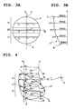
optical region 11 is achieved as shown inFIGS. 3 and 4 , so that the curvature radius R from a rotational axis C parallel to the vertical axis N of the lensoptical region 11 is the same in the lateral direction M, maximum at the upper end point A along the direction of the vertical axis N (R = Rh1), sequentially reduced toward thedistance portion 12, theintermediate portion 14, and the near portion 13 (R = Rh2, Rh3, Rh4), and minimum at the lower end point B (R = Rh5). More specifically, in the lensoptical region 11, the curvature radius R is set to the curvature radius Rh1 at the upper end point A, the same curvature radius Rh2 at point a, point b, and point c on the same lateral axis M, the same curvature radius Rh3 at point d, point e, and point f on the other same lateral axis M, the same curvature radius Rh4 at point g, point h, and point i on the other same lateral axis M, and the curvature radius Rh5 at the lower end point B. - Also, as shown in
FIG. 1 , in the far andnear contact lens 10, aprism ballast 17 as a rotation preventing mechanism is formed on the side of the lower end point B along the direction of the vertical axis N of the lensoptical region 11. As shown inFIG. 2 , theprism ballast 17 is configured so that the portion on the side of the lower end point B of the lensoptical region 11 is formed thick to function as a weight that prevents or suppresses rotation of the far andnear contact lens 10 that is fitted on thecornea 2 of the eye 1, and always keeps the lower end point B of the lensoptical region 11 positioned at a lower position. The presence of theprism ballast 17 ensures that the far andnear contact lens 10 fitted on thecornea 2 of the eye 1 is always stably positioned with thedistance portion 12 of the lensoptical region 11 on the upper part of the eye 1, and thenear portion 13 on the lower part of the eye 1. -
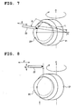
FIGS. 7 and 8 will be used to describe the manufacturing process for the far andnear contact lens 10 whereby the aforementioned curvature radius R is formed in theconvex surface 16A of the lensoptical region 11, and theprism ballast 17 is formed on the side of the lower end point B of the lensoptical region 11. - In one manufacturing process, as shown in
Fig. 7 , acontact lens material 20 to be processed into a far andnear contact lens 10 is held in alens holder 21 and rotated around the rotation axis C, and while acutting tool 22 is turned around an original point O, thiscutting tool 22 approaches or turns against the direction of E with respect to the original point O, thereby changing a distance L between the cuttingtool 22 and the original point O. Along with an increase of a rotation angle θ of thecutting tool 22 that turns from the position corresponding to the upper end point A of the near andfar contact lens 10, the cuttingtool 22 is approached to the original point O. Whereby, theconvex surface 16A having the aforementioned curvature radius R is formed in the lensoptical region 11, theprism ballast 17 is processed, and the far andnear contact lens 10 is manufactured. - As shown in
FIG. 8 , in another manufacturing process, by moving thecutting tool 22 in a direction of G that coincides with the direction of the vertical axis N of the lensoptical region 11, and in a direction F orthogonal to the direction of G, theconvex surface 16A having the curvature radius R is formed in the lensoptical region 11, theprism ballast 17 is processed, and the far andnear contact lens 10 is manufactured, while thecontact lens material 20 is held in thelens holder 21 and rotated around the rotation axis C. - As shown in
FIG. 9 , when the far andnear contact lens 10 manufactured as described above is fitted on thecornea 2 of the eye 1, since theprism ballast 17 is provided in the far andnear contact lens 10, thedistance portion 12 of the lensoptical region 11 is stably positioned on the upper part of the eye 1, and thenear portion 13 is stably positioned on the lower part of the eye 1. Since most of thepupil 3 of the eye 1 therefore corresponds to thedistance portion 12 of the far andnear contact lens 10 in far vision, thepupil 3 can take in more light from thedistance portion 12 of the far andnear contact lens 10, and a clear far vision image can be obtained by thedistance portion 12. In downward vision, being the near vision, since thelower eyelid 6 pushes-up the far andnear contact lens 10 upward, a major part of thepupil 3 of the eye 1 corresponds to thenear portion 13 of the far andnear contact lens 10, thepupil 3 takes in more light from thenear portion 13 of the far andnear contact lens 10, and a clear near-visual image can be obtained by thenear portion 13. - With the aforementioned structure, the following advantages (1) through (4) are exhibited according to the aforementioned embodiment.
- (1) Since the power distribution along the direction of the vertical axis N of the lens
optical region 11 in the far andnear contact lens 10 is set in accordance with the formula (1), the power distribution in the lensoptical region 11 of the far andnear contact lens 10 can be set as a specific power distribution adapted to the prescription of the eye 1 of the lens wearer. Accordingly, the power fluctuation in thedistance portion 12 and thenear portion 13 of the far andnear contact lens 10 can be minimized, and a stable image (far vision image, near-vision image) can therefore be secured between thedistance portion 12 and thenear portion 13. -
- (2) Since the power distribution along the direction of the vertical axis N of the lens
optical region 11 in the far andnear contact lens 10 is set in accordance with the formula (1), A fine power variation corresponding to the movement of the far andnear contact lens 10 or change of the visual line moving among thedistance portion 12, theintermediate portion 14, and thenear portion 13 of the far andnear contact lens 10 can be provided in the lens optical region 11 (particularly the boundaries of thedistance portion 12, theintermediate portion 14, and the near portion 13). Image blurring and ghosting can therefore be kept to a minimum, lowering of the contrast of the image can be prevented, and wavering or jumping of the image due to excessive power variation can be suppressed. As a result, a clear image can be maintained. -
- (3) The
distance portion 12, theintermediate portion 14, and thenear portion 13 are arranged sequentially from the upper end point A to the lower end point B along the direction of the vertical axis N in the lensoptical region 11 of the far andnear contact lens 10. Thedistance portion 12 can therefore be set in a wide range in the necessary location (upper side portion of the lens optical region 11) for far vision, and thenear portion 13 can be set in a wide range in the necessary location (lower side portion of the lens optical region 11) for near vision. As a result, the far andnear contact lens 10 having an excellent sight aiding efficiency can be obtained. -
- (4) Since the far and
near contact lens 10 is provided with theprism ballast 17 as a rotation preventing mechanism on the side of the lower end point B along the direction of the vertical axis N of the lensoptical region 11, rotation of the far andnear contact lens 10 fitted on thecornea 2 of the eye 1 can be prevented or suppressed by theprism ballast 17. Accordingly, a clear far vision image and a clear near-vision image can be stably obtained through thedistance portion 12 and thenear portion 13, respectively, of the far andnear contact lens 10. -
FIG. 10 is a front view showing a modified example of the far and near contact lens shown inFIG. 1 . In this modified example, the same reference symbols are used to indicate components that are the same as those of the far andnear contact lens 10 according to Embodiment 1, and description thereof is omitted. - In the far and
near contact lens 30 in this modified example, the prescribed direction of the lensoptical region 11 in which thedistance portion 12, theintermediate portion 14, and thenear portion 13 are sequentially arranged is the direction of a tilted axis K that is tilted towards the nose of the face from the direction of the vertical axis N of the lensoptical region 11, which coincides with the vertical direction (upper and lower direction) of the eye 1. Accordingly, the upper end point A and the lower end point B of the lensoptical region 11 are set on the tilted axis K. Theprism ballast 17 is also provided on the side of the lower end point BB on the vertical axis N in the lensoptical region 11. - The
distance portion 12, theintermediate portion 14, and thenear portion 13 are thus sequentially arranged along the tilted axis K that is tilted towards the nose from the vertical axis N of the lensoptical region 11, so as to excellently respond to the characteristic of the eye that converges in the near vision. Namely, since a further larger portion of thepupil 3 of the eye 1 corresponds to thenear portion 13 of the far andnear contact lens 10 in the near vision, thepupil 3 can take in even more light that passes through thenear portion 13 of the far andnear contact lens 10, and a clear near-vision image can be ensured. In addition, in this modified example also, the same advantages as the advantages of (1) to (4) of the aforementioned embodiments can be exhibited. -
FIG. 11 is a front view showing another modified example of the far and near contact lens shown inFIG. 1 . In this modified example, the same reference symbols are used to indicate components that are the same as those of the far andnear contact lens 10 in Embodiment 1, and description thereof is omitted. - In the far and
near contact lens 40 according to another modified example, the rotation preventing mechanism in the far andnear contact lens 10 of the first embodiment is differentiated, and instead of using theprism ballast 17, slab-offparts flange part 15 along the direction of the vertical axis N cut away. When the far andnear contact lens 40 is fitted on thecornea 2 of the eye 1, the slab-offparts upper eyelid 5 and thelower eyelid 6, respectively, whereby the far andnear contact lens 40 is prevented from rotating. The slab-offparts flange part 15 in the far andnear contact lens 40. Accordingly, in this modified example also, the same advantages of the advantages of (1) to (4) of the far andnear contact lens 10 of the first embodiment can be exhibited. - In the far and
near contact lens 10 according toEmbodiment 2, the power distribution in accordance with the formula (1) is set along the direction of the vertical axis N of the lensoptical region 11 in at least one (usually theconvex surface 16A) of theconvex surface 16A and theconcave surface 16B of the lensoptical region 11 in the same manner as embodiment 1, and the astigmatism degree is also set in the sameconvex surface 16A orconcave surface 16B (usually theconvex surface 16A) as that on which this power distribution is set. The astigmatism degree is set along the direction of the lateral axis M orthogonal to the direction of the vertical axis N in which the power distribution according to the formula (1) is set. - Therefore, according to the far and
near contact lens 10 of theembodiment 2, the function of aiding the far vision and the near vision by thedistance portion 12 and thenear portion 13 can be exhibited based on the power distribution set according to the formula (1), and in addition, the function of correcting the astigmatism (particularly such as inverted astigmatism and straight astigmatism) can be exhibited. - In the far and
near contact lens 10 according to anembodiment 3, the power distribution according to the formula (1) is set along the direction of the vertical axis N of the lensoptical region 11 in at least one of theconvex surface 16A and theconcave surface 16B of the lens optical region 11 (usually theconvex surface 16A), and the other one of theconvex surface 16A and theconcave surface 16B (usually theconcave surface 16B) is formed to be the toric surface having the astigmatism correcting function. The toric surface is formed so as to correspond to the shape of thecornea 2 in an astigmatic state in the eye 1 of the lens wearer. - Since the
cornea 2 in the astigmatic state has different curvature radius of two orthogonal axes, the toric surface formed on theconcave surface 16B in the lensoptical region 11 of the far andnear contact lens 10 is formed so as to have different curvature radius of two orthogonal axes corresponding to the shape of thecornea 2 in the astigmatic state. - In the far and
near contact lens 10 according to theembodiment 3, the power distribution according to the formula (1) is set along the direction of the vertical axis N of the lensoptical region 11 in theconvex surface 16A of the lensoptical region 11, and theconcave surface 16B is formed to be the toric surface having the astigmatism correcting function. The toric surface can therefore perform the astigmatism correcting function, irrespective of the power distribution according to the formula (1). Therefore, the toric surface of theconcave surface 16B can exhibit the astigmatism correcting function to almost all astigmatism such as inverted astigmatism, straight astigmatism, and oblique astigmatism. - In the far and
near contact lens 10 according to theembodiment 3, since theconcave surface 16B is a toric surface formed according to the shape of the cornea 1 in the astigmatic state, the astigmatism correcting function can be exhibited by fitting thisconcave surface 16B on thecornea 2 of the eye 1 of the lens wearer, and the rotation preventing function of this far andnear contact lens 10 can also be exhibited. In addition, when the rotation preventing mechanism such as theprism ballast 17 or the slab-offparts optical region 11 in the far andnear contact lens 10, prevention of the rotation of this far andnear contact lens 10 can be further effectively realized, by a synergetic effect of the rotation preventing mechanism of theprism ballast 17 or the slab-off - The present invention has been described above based on the embodiments, but the present invention is not limited thereto. For example, the aforementioned first embodiment and both modified examples, the second embodiment and the third embodiment describe a case that the ocular lens is the contact lens. However, the present invention may provide a spectacle lens implanted into the eye, or the spectacle lens of a spectacle which is worn with spacing from the
cornea 2. -
-
FIG. 1 is a front view showing a far and near contact lens according to an embodiment 1 of an ocular lens of the present invention; -
FIG. 2 is a sectional view taken along the line II-II ofFIG. 1 ; -
FIG. 3 shows a lens optical region of the far and near contact lens ofFIG. 1 , wherein (A) is a front view and (B) is a side view; -
FIG. 4 is a perspective view showing a shape of the lens optical region shown ofFIG. 3 ; -
FIG. 5 is a graph showing a power distribution (when a distance portion shows a minus power) in the lens optical region ofFIG. 3 ; -
FIG. 6 is a graph showing the power distribution (when the distance portion shows a plus power) in the lens optical region ofFIG. 3 ; -
FIG. 7 is a perspective view showing a manufacturing process of the far and near contact lens ofFIG. 1 ; -
FIG. 8 is a perspective view showing other manufacturing process of the far and near contact lens ofFIG. 1 ; -
FIG. 9 is a side view showing a use state of the far and near contact lens ofFIG. 1 , together with the eyeball; -
FIG. 10 is a front view showing a modified example of the far and near contact lens ofFIG. 1 ; -
FIG. 11 is a front view showing other modified example of the far and near contact lens ofFIG. 1 ; and -
FIG. 12 is a front view of a conventional simultaneous perception type far and near contact lens showing a concentric circular power distribution. -
- 1
- eye
- 2
- cornea
- 3
- pupil
- 10
- far and near contact lens
- 11
- lens optical region
- 12
- distance portion
- 13
- near portion
- 14
- intermediate portion
- 17
- prism ballast
- 30
- far and near contact lens
- N
- vertical axis (prescribed direction)
- A
- upper end point (one end)
- B
- lower end point (other end)
- K
- tilted axis (prescribed direction)
Claims (12)
- An ocular lens, which is a progressive multifocal ocular lens having a distance portion for aiding a far vision, an intermediate portion for aiding an intermediate vision, and a near portion for aiding a near vision in a lens optical region;
in a state that said distance portion, said intermediate portion, and said near portion being arranged sequentially from an upper end to a lower end of an optical part from one end to another end along a prescribed direction of said lens optical region, with a power of these regions changing continuously. - An ocular lens, which is a progressive multifocal ocular lens having a distance portion for aiding a far vision, a near portion for aiding a near vision, and an intermediate portion in which a power is changed progressively between the distance portion and the near portion, in a lens optical region,
so that said distance portion, said intermediate portion, and said near portion are arranged sequentially from one end to another end along a prescribed direction of said lens optical region; and
a power distribution of said lens optical region along said prescribed direction is set according to the following formula (1) :

wherein each symbol in the formula (1) is defined as follows:PowerDist: power distribution (unit: D (diopter));P-Power: power (unit: D) at one end point of the lens optical region;Max-Add: power difference (unit: D) between one end point and the other end point of the lens optical region;Bnf: distance (unit: mm) from one end point of the lens optical region to a boundary between a distance power of the distance portion and a near power of the near portion;Wave: power variation coefficient (wave degree); andx: distance (unit: mm) from one end point of the lens optical region. - The ocular lens according to claim 1, wherein
ranges of values of said P-Power, said Max-Add, said Bnf, and said Wave are as follows:


and
- The ocular lens according to claim 1, 2, or 3, wherein
the power distribution of said lens optical region is set so that a curvature radius of at least one of a front surface and a back surface of the lens optical region is changed in a range from the distance portion to the near portion through the intermediate portion. - The ocular lens according to any of claims 1, 2 to 4, wherein said prescribed direction is a vertical direction of an eye during wearing the ocular lens.
- The ocular lens according to any of claims 1, 2 to 4, wherein said prescribed direction is set so as to tilt toward a nose side of a face from the vertical direction of the eye during wearing the ocular lens.
- The ocular lens according to any of claims 1, 2 to 6, wherein said ocular lens is a contact lens having a rotation preventing mechanism of preventing a rotation of this lens, at an end part along the prescribed direction.
- The ocular lens according to claim 7, wherein said rotation preventing mechanism is a prism ballast provided at the other end side along the prescribed direction of the contact lens.
- The ocular lens according to claim 7, wherein said rotation preventing mechanism is a slab-off provided at one end part or both end parts along the prescribed direction of the contact lens.
- The ocular lens according to any of claims 1, 2 to 9, wherein the power distribution according to the formula (1) is set along the prescribed direction of the lens optical region in at least one of the front surface and the back surface of said lens optical region, and an astigmatism degree is set in a direction orthogonal to said prescribed direction.
- The ocular lens according to any of claims 1, 2 to 9, wherein the power distribution according to the formula (1) is set along the prescribed direction of the lens optical region in at least one of the front surface and the back surface of said lens optical region, and the other of said front surface and back surface is formed to be a toric surface having an astigmatism correcting function.
- The ocular lens according to claim 11, wherein said ocular lens is a contact lens in which a back surface of a lens optical region is fitted on a cornea of an eye, and the back surface is a toric surface formed corresponding to a shape of the cornea in an astigmatic state.
Applications Claiming Priority (2)
| Application Number | Priority Date | Filing Date | Title |
|---|---|---|---|
| JP2005164164 | 2005-06-03 | ||
| PCT/JP2006/310872 WO2006129707A1 (en) | 2005-06-03 | 2006-05-31 | Eye-use lens |
Publications (3)
| Publication Number | Publication Date |
|---|---|
| EP1901108A1 true EP1901108A1 (en) | 2008-03-19 |
| EP1901108A4 EP1901108A4 (en) | 2009-06-10 |
| EP1901108B1 EP1901108B1 (en) | 2020-09-09 |
Family
ID=37481636
Family Applications (1)
| Application Number | Title | Priority Date | Filing Date |
|---|---|---|---|
| EP06756805.5A Not-in-force EP1901108B1 (en) | 2005-06-03 | 2006-05-31 | Eye-use lens |
Country Status (5)
| Country | Link |
|---|---|
| US (1) | US7819523B2 (en) |
| EP (1) | EP1901108B1 (en) |
| JP (1) | JP4807801B2 (en) |
| CN (1) | CN101208628B (en) |
| WO (1) | WO2006129707A1 (en) |
Cited By (1)
| Publication number | Priority date | Publication date | Assignee | Title |
|---|---|---|---|---|
| EP3168674A1 (en) * | 2015-11-16 | 2017-05-17 | Johnson & Johnson Vision Care Inc. | Truncated translating contact lens with optimized performance and method of design |
Families Citing this family (23)
| Publication number | Priority date | Publication date | Assignee | Title |
|---|---|---|---|---|
| US7481533B2 (en) * | 2006-10-30 | 2009-01-27 | Johnson & Johnson Vision Care, Inc | Method for designing multifocal contact lenses |
| US8974526B2 (en) | 2007-08-27 | 2015-03-10 | Amo Groningen B.V. | Multizonal lens with extended depth of focus |
| NL2002540C2 (en) | 2009-02-17 | 2010-08-18 | Oculentis B V | Ophthalmic lens with optical sectors. |
| JP5984263B2 (en) | 2010-03-03 | 2016-09-06 | ブライアン・ホールデン・ビジョン・インスティチュートBrien Holden Vision Institute | Contact lenses for myopic eyes and methods of treating myopia |
| US9817246B2 (en) * | 2010-12-01 | 2017-11-14 | Amo Groningen B.V. | Multifocal lens having an optical add power progression, and a system and method of providing same |
| US9028063B2 (en) * | 2011-08-26 | 2015-05-12 | Johnson & Johnson Vision Care, Inc. | Translating presbyopic contact lens pair |
| US8888277B2 (en) * | 2012-10-26 | 2014-11-18 | Johnson & Johnson Vision Care, Inc. | Contact lens with improved fitting characteristics |
| US9709822B2 (en) | 2015-03-11 | 2017-07-18 | Vance M. Thompson | Orthokeratology lens with displaced shaping zone |
| US10845622B2 (en) | 2015-09-15 | 2020-11-24 | Largan Medical Co., Ltd. | Multifocal contact lens and contact lens product |
| US12298602B2 (en) | 2015-09-15 | 2025-05-13 | Largan Medical Co., Ltd. | Multifocal contact lens and contact lens product |
| CA3013857A1 (en) | 2016-02-09 | 2017-08-17 | Amo Groningen B.V. | Progressive power intraocular lens, and methods of use and manufacture |
| US10274751B2 (en) * | 2016-07-05 | 2019-04-30 | Bausch & Lomb Incorporated | Prism ballasted contact lens |
| TWI749325B (en) * | 2016-09-02 | 2021-12-11 | 星歐光學股份有限公司 | Contact lens product |
| CN106444058B (en) * | 2016-09-28 | 2019-08-23 | 惠州Tcl移动通信有限公司 | Virtual reality shows helmet and optical module |
| US20180196281A1 (en) * | 2017-01-06 | 2018-07-12 | eyeBrain Medical, Inc. | Prismatic contact lens |
| JP6188974B1 (en) | 2017-01-24 | 2017-08-30 | Hoya株式会社 | Ophthalmic lens, design method thereof, production method thereof, and ophthalmic lens set |
| JP2019144278A (en) * | 2017-12-28 | 2019-08-29 | ホヤ レンズ タイランド リミテッドHOYA Lens Thailand Ltd | Progressive power lens and manufacturing method therefor |
| JP6559866B1 (en) | 2018-10-11 | 2019-08-14 | Hoya株式会社 | Ophthalmic lens, design method thereof, production method thereof, and ophthalmic lens set |
| CN110058426A (en) * | 2018-11-27 | 2019-07-26 | 上海宜酷光学科技有限公司 | Stealthy double light anti-blue light eyeglasses and its working method |
| US11886046B2 (en) | 2019-12-30 | 2024-01-30 | Amo Groningen B.V. | Multi-region refractive lenses for vision treatment |
| US11963868B2 (en) | 2020-06-01 | 2024-04-23 | Ast Products, Inc. | Double-sided aspheric diffractive multifocal lens, manufacture, and uses thereof |
| JP2023122709A (en) | 2022-02-24 | 2023-09-05 | Hoya株式会社 | ophthalmic lens, design method thereof, manufacturing method thereof, and ophthalmic lens set |
| JP2023122708A (en) | 2022-02-24 | 2023-09-05 | Hoya株式会社 | ophthalmic lens, design method thereof, manufacturing method thereof, and ophthalmic lens set |
Family Cites Families (21)
| Publication number | Priority date | Publication date | Assignee | Title |
|---|---|---|---|---|
| GB1025677A (en) | 1962-10-02 | 1966-04-14 | Irving P Filderman | Contact lenses |
| NL168626C (en) * | 1973-08-16 | 1982-04-16 | American Optical Corp | LENS FOR GLASSES WITH VARIETY OF STRENGTH. |
| FR2495789B1 (en) * | 1980-12-05 | 1986-02-14 | Suwa Seikosha Kk | PROGRESSIVE MULTIFOCAL LENS |
| JPS5794714A (en) | 1980-12-05 | 1982-06-12 | Seiko Epson Corp | Progressive multifocus lens |
| US4580882A (en) * | 1983-04-21 | 1986-04-08 | Benjamin Nuchman | Continuously variable contact lens |
| US4693572A (en) * | 1985-06-03 | 1987-09-15 | Fused Kontacts Of Chicago, Inc. | Monocentric bifocal corneal contact lens |
| EP0248489A3 (en) * | 1986-06-02 | 1989-09-06 | Gregory N. Miller | Contact lens and method of making same |
| TW275112B (en) * | 1995-03-15 | 1996-05-01 | Ciba Geigy Ag | Rotationally stabilized contact lens and methods of lens stabilization |
| CN1164037A (en) | 1995-03-15 | 1997-11-05 | 诺瓦提斯公司 | Rotationally stabilized contact lens and methods of lens stabilization |
| JP3852116B2 (en) * | 1995-11-24 | 2006-11-29 | セイコーエプソン株式会社 | Progressive multifocal lens and spectacle lens |
| JPH1048576A (en) * | 1996-08-02 | 1998-02-20 | Takao Kurosaki | Contact lens |
| DE19726918A1 (en) * | 1997-06-25 | 1999-01-07 | Woehlk Contact Linsen Gmbh | Multifocal contact lens |
| JP3683093B2 (en) * | 1998-03-11 | 2005-08-17 | 株式会社メニコン | Multifocal contact lens |
| US6030077A (en) * | 1998-03-11 | 2000-02-29 | Menicon Co., Ltd. | Multifocal ocular lens having intermediate region with continuously varying optical power |
| US6467903B1 (en) | 2000-03-31 | 2002-10-22 | Ocular Sciences, Inc. | Contact lens having a uniform horizontal thickness profile |
| JP3798613B2 (en) | 2000-10-20 | 2006-07-19 | Hoyaヘルスケア株式会社 | Multifocal lens design method |
| JP4164550B2 (en) * | 2001-10-12 | 2008-10-15 | セイコーオプティカルプロダクツ株式会社 | Progressive power spectacle lens |
| US6921168B2 (en) * | 2002-07-24 | 2005-07-26 | Novartis Ag | Translating contact lens having a ramped ridge |
| US7118215B2 (en) * | 2002-10-08 | 2006-10-10 | Hoya Corporation | Method for determining optical value of lens of eyeglasses, process for producing lens of eyeglasses, lens of eyeglasses and its ordering/ordr receiving system |
| US7063422B2 (en) * | 2003-04-16 | 2006-06-20 | Novartis Ag | Multifocal ophthalmic lens |
| US7080906B2 (en) * | 2003-11-12 | 2006-07-25 | Novartis Ag | Translating bifocal wear modality |
-
2006
- 2006-05-31 CN CN200680019554XA patent/CN101208628B/en not_active Expired - Fee Related
- 2006-05-31 EP EP06756805.5A patent/EP1901108B1/en not_active Not-in-force
- 2006-05-31 JP JP2007519034A patent/JP4807801B2/en not_active Expired - Fee Related
- 2006-05-31 US US11/921,447 patent/US7819523B2/en active Active
- 2006-05-31 WO PCT/JP2006/310872 patent/WO2006129707A1/en not_active Ceased
Cited By (5)
| Publication number | Priority date | Publication date | Assignee | Title |
|---|---|---|---|---|
| EP3168674A1 (en) * | 2015-11-16 | 2017-05-17 | Johnson & Johnson Vision Care Inc. | Truncated translating contact lens with optimized performance and method of design |
| CN106896522A (en) * | 2015-11-16 | 2017-06-27 | 庄臣及庄臣视力保护公司 | Truncation parallel-moving type haptic lens and method for designing with optimization performance |
| US9880399B2 (en) | 2015-11-16 | 2018-01-30 | Johnson & Johnson Vision Care, Inc. | Truncated translating contact lens with optimized performance and method of design |
| US10151935B2 (en) | 2015-11-16 | 2018-12-11 | Johnson & Johnson Vision Care, Inc. | Truncated translating contact lens with optimized performance and method of design |
| US10379380B2 (en) | 2015-11-16 | 2019-08-13 | Johnson & Johnson Vision Care, Inc. | Truncated translating contact lens with optimized performance and method of design |
Also Published As
| Publication number | Publication date |
|---|---|
| CN101208628A (en) | 2008-06-25 |
| EP1901108B1 (en) | 2020-09-09 |
| JPWO2006129707A1 (en) | 2009-01-08 |
| CN101208628B (en) | 2011-05-18 |
| US20090303433A1 (en) | 2009-12-10 |
| EP1901108A4 (en) | 2009-06-10 |
| WO2006129707A1 (en) | 2006-12-07 |
| US7819523B2 (en) | 2010-10-26 |
| JP4807801B2 (en) | 2011-11-02 |
Similar Documents
| Publication | Publication Date | Title |
|---|---|---|
| EP1901108B1 (en) | Eye-use lens | |
| EP4296762B1 (en) | Spectacle lens and frame glasses | |
| EP0102223B1 (en) | Bifocal soft contact lens | |
| EP2955566B1 (en) | Toric lens | |
| EP2033043B1 (en) | Means for controlling the progression of myopia | |
| KR101921886B1 (en) | Translating presbyopic contact lens pair | |
| EP2622404B1 (en) | Asymmetric translating presbyopic contact lens | |
| JP7013123B2 (en) | Cut-off translational contact lenses with optimization performance and design methods | |
| KR101878215B1 (en) | Translating presbyopic contact lens | |
| EP1242845B1 (en) | Soft multifocal contact lens | |
| EP2574975B1 (en) | Optical lens, method for manufacturing an optical lens, and apparatus for manufacturing optical lens | |
| WO2005106570A1 (en) | A multifocal contact lens | |
| EP0702257B1 (en) | Progressive power presbyopia-correcting ophthalmic lenses | |
| CN112204456A (en) | Photochromic soft contact lenses with cosmetic and efficacy considerations | |
| KR20130139940A (en) | Translating presbyopic contact lens | |
| EP3575858B1 (en) | Ophthalmic lens, method of design therefor, method of manufacture therefor, and ophthalmic lens set | |
| JP5017542B2 (en) | Aspheric spectacle lens and method of manufacturing aspheric spectacle lens | |
| EP4270097B1 (en) | Ophthalmic lens for preventing progression of myopia, and spectacles with the same | |
| JPH07294859A (en) | Progressive multi-focus lens | |
| CA1244687A (en) | Contact lens | |
| EP4369079B1 (en) | Contact lens | |
| HK1118343A (en) | Eye-use lens |
Legal Events
| Date | Code | Title | Description |
|---|---|---|---|
| PUAI | Public reference made under article 153(3) epc to a published international application that has entered the european phase |
Free format text: ORIGINAL CODE: 0009012 |
|
| 17P | Request for examination filed |
Effective date: 20080102 |
|
| AK | Designated contracting states |
Kind code of ref document: A1 Designated state(s): DE ES FR GB IT NL |
|
| DAX | Request for extension of the european patent (deleted) | ||
| RBV | Designated contracting states (corrected) |
Designated state(s): DE ES FR GB IT NL |
|
| A4 | Supplementary search report drawn up and despatched |
Effective date: 20090511 |
|
| 17Q | First examination report despatched |
Effective date: 20090709 |
|
| RAP1 | Party data changed (applicant data changed or rights of an application transferred) |
Owner name: HOYA CORPORATION |
|
| RAP1 | Party data changed (applicant data changed or rights of an application transferred) |
Owner name: HOYA CORPORATION |
|
| STAA | Information on the status of an ep patent application or granted ep patent |
Free format text: STATUS: EXAMINATION IS IN PROGRESS |
|
| GRAP | Despatch of communication of intention to grant a patent |
Free format text: ORIGINAL CODE: EPIDOSNIGR1 |
|
| STAA | Information on the status of an ep patent application or granted ep patent |
Free format text: STATUS: GRANT OF PATENT IS INTENDED |
|
| INTG | Intention to grant announced |
Effective date: 20200528 |
|
| RIN1 | Information on inventor provided before grant (corrected) |
Inventor name: SHIMOJO, AKIRA |
|
| GRAS | Grant fee paid |
Free format text: ORIGINAL CODE: EPIDOSNIGR3 |
|
| GRAA | (expected) grant |
Free format text: ORIGINAL CODE: 0009210 |
|
| STAA | Information on the status of an ep patent application or granted ep patent |
Free format text: STATUS: THE PATENT HAS BEEN GRANTED |
|
| AK | Designated contracting states |
Kind code of ref document: B1 Designated state(s): DE ES FR GB IT NL |
|
| REG | Reference to a national code |
Ref country code: GB Ref legal event code: FG4D |
|
| REG | Reference to a national code |
Ref country code: DE Ref legal event code: R096 Ref document number: 602006059664 Country of ref document: DE |
|
| REG | Reference to a national code |
Ref country code: NL Ref legal event code: MP Effective date: 20200909 |
|
| PG25 | Lapsed in a contracting state [announced via postgrant information from national office to epo] |
Ref country code: NL Free format text: LAPSE BECAUSE OF FAILURE TO SUBMIT A TRANSLATION OF THE DESCRIPTION OR TO PAY THE FEE WITHIN THE PRESCRIBED TIME-LIMIT Effective date: 20200909 |
|
| PG25 | Lapsed in a contracting state [announced via postgrant information from national office to epo] |
Ref country code: ES Free format text: LAPSE BECAUSE OF FAILURE TO SUBMIT A TRANSLATION OF THE DESCRIPTION OR TO PAY THE FEE WITHIN THE PRESCRIBED TIME-LIMIT Effective date: 20200909 |
|
| REG | Reference to a national code |
Ref country code: DE Ref legal event code: R097 Ref document number: 602006059664 Country of ref document: DE |
|
| PLBE | No opposition filed within time limit |
Free format text: ORIGINAL CODE: 0009261 |
|
| STAA | Information on the status of an ep patent application or granted ep patent |
Free format text: STATUS: NO OPPOSITION FILED WITHIN TIME LIMIT |
|
| 26N | No opposition filed |
Effective date: 20210610 |
|
| PG25 | Lapsed in a contracting state [announced via postgrant information from national office to epo] |
Ref country code: IT Free format text: LAPSE BECAUSE OF FAILURE TO SUBMIT A TRANSLATION OF THE DESCRIPTION OR TO PAY THE FEE WITHIN THE PRESCRIBED TIME-LIMIT Effective date: 20200909 |
|
| GBPC | Gb: european patent ceased through non-payment of renewal fee |
Effective date: 20210531 |
|
| PG25 | Lapsed in a contracting state [announced via postgrant information from national office to epo] |
Ref country code: GB Free format text: LAPSE BECAUSE OF NON-PAYMENT OF DUE FEES Effective date: 20210531 |
|
| PG25 | Lapsed in a contracting state [announced via postgrant information from national office to epo] |
Ref country code: FR Free format text: LAPSE BECAUSE OF NON-PAYMENT OF DUE FEES Effective date: 20210531 |
|
| P01 | Opt-out of the competence of the unified patent court (upc) registered |
Effective date: 20230418 |
|
| PGFP | Annual fee paid to national office [announced via postgrant information from national office to epo] |
Ref country code: DE Payment date: 20230404 Year of fee payment: 18 |
|
| REG | Reference to a national code |
Ref country code: DE Ref legal event code: R119 Ref document number: 602006059664 Country of ref document: DE |
|
| PG25 | Lapsed in a contracting state [announced via postgrant information from national office to epo] |
Ref country code: DE Free format text: LAPSE BECAUSE OF NON-PAYMENT OF DUE FEES Effective date: 20241203 |