EP1901029B1 - Position and orientation measurement method and apparatus - Google Patents
Position and orientation measurement method and apparatus Download PDFInfo
- Publication number
- EP1901029B1 EP1901029B1 EP07116329.9A EP07116329A EP1901029B1 EP 1901029 B1 EP1901029 B1 EP 1901029B1 EP 07116329 A EP07116329 A EP 07116329A EP 1901029 B1 EP1901029 B1 EP 1901029B1
- Authority
- EP
- European Patent Office
- Prior art keywords
- image
- capture device
- subjective
- orientation
- image capture
- Prior art date
- Legal status (The legal status is an assumption and is not a legal conclusion. Google has not performed a legal analysis and makes no representation as to the accuracy of the status listed.)
- Not-in-force
Links
- 238000000691 measurement method Methods 0.000 title claims description 4
- 238000001514 detection method Methods 0.000 claims description 64
- 238000004364 calculation method Methods 0.000 claims description 55
- 238000000034 method Methods 0.000 claims description 49
- 238000005259 measurement Methods 0.000 claims description 39
- 230000003287 optical effect Effects 0.000 claims description 17
- 238000012937 correction Methods 0.000 claims description 7
- 238000013500 data storage Methods 0.000 description 27
- 239000013598 vector Substances 0.000 description 25
- 239000011159 matrix material Substances 0.000 description 20
- 238000012545 processing Methods 0.000 description 17
- 238000012986 modification Methods 0.000 description 8
- 230000004048 modification Effects 0.000 description 8
- 238000004590 computer program Methods 0.000 description 7
- 238000010586 diagram Methods 0.000 description 6
- 239000003550 marker Substances 0.000 description 5
- 230000008569 process Effects 0.000 description 5
- 230000003190 augmentative effect Effects 0.000 description 4
- 239000003086 colorant Substances 0.000 description 4
- 230000002035 prolonged effect Effects 0.000 description 2
- 230000003252 repetitive effect Effects 0.000 description 2
- 238000012552 review Methods 0.000 description 2
- 230000009466 transformation Effects 0.000 description 2
- 230000008859 change Effects 0.000 description 1
- 230000000052 comparative effect Effects 0.000 description 1
- 230000002542 deteriorative effect Effects 0.000 description 1
- 230000002708 enhancing effect Effects 0.000 description 1
- 238000002372 labelling Methods 0.000 description 1
- 230000009467 reduction Effects 0.000 description 1
- 239000004065 semiconductor Substances 0.000 description 1
- 238000009331 sowing Methods 0.000 description 1
- 238000007619 statistical method Methods 0.000 description 1
- 230000001131 transforming effect Effects 0.000 description 1
- 230000000007 visual effect Effects 0.000 description 1
Images

Classifications
-
- G—PHYSICS
- G01—MEASURING; TESTING
- G01B—MEASURING LENGTH, THICKNESS OR SIMILAR LINEAR DIMENSIONS; MEASURING ANGLES; MEASURING AREAS; MEASURING IRREGULARITIES OF SURFACES OR CONTOURS
- G01B11/00—Measuring arrangements characterised by the use of optical techniques
- G01B11/002—Measuring arrangements characterised by the use of optical techniques for measuring two or more coordinates
-
- G—PHYSICS
- G01—MEASURING; TESTING
- G01B—MEASURING LENGTH, THICKNESS OR SIMILAR LINEAR DIMENSIONS; MEASURING ANGLES; MEASURING AREAS; MEASURING IRREGULARITIES OF SURFACES OR CONTOURS
- G01B11/00—Measuring arrangements characterised by the use of optical techniques
- G01B11/24—Measuring arrangements characterised by the use of optical techniques for measuring contours or curvatures
- G01B11/25—Measuring arrangements characterised by the use of optical techniques for measuring contours or curvatures by projecting a pattern, e.g. one or more lines, moiré fringes on the object
- G01B11/2504—Calibration devices
-
- G—PHYSICS
- G06—COMPUTING; CALCULATING OR COUNTING
- G06T—IMAGE DATA PROCESSING OR GENERATION, IN GENERAL
- G06T7/00—Image analysis
- G06T7/70—Determining position or orientation of objects or cameras
- G06T7/73—Determining position or orientation of objects or cameras using feature-based methods
-
- G—PHYSICS
- G06—COMPUTING; CALCULATING OR COUNTING
- G06T—IMAGE DATA PROCESSING OR GENERATION, IN GENERAL
- G06T2207/00—Indexing scheme for image analysis or image enhancement
- G06T2207/30—Subject of image; Context of image processing
- G06T2207/30244—Camera pose
Definitions
- the present invention relates to a method and apparatus for measuring the position and orientation of an object and, more particularly, those of an image capture device.
- Measurement of the position and orientation of an image capture unit such as a camera hereinafter as needed
- a camera such as a camera or the like used to capture an image of a physical space
- a mixed reality system that integrally presents the physical space and a virtual space.
- Japanese Patent Laid-Open No. 11-084307 Japanese Patent Laid-Open No. 2000-041173 , and A. State, G. Hirota, D. T. Chen, B. Garrett, and M. Livingston: Superior augmented reality registration by integrating landmark tracking and magnetic tracking, Proc. SIGGRAPH '96, pp. 429 - 438, July 1996 . disclose schemes for measuring the position and orientation of a camera using a position and orientation sensor. These related arts also disclose schemes for correcting measurement errors of the position and orientation sensor using markers whose allocation positions on the physical space are known or feature points whose positions on the physical space are known (markers and feature points will be collectively referred to as indices hereinafter).
- Japanese Patent Laid-Open No. 2004-205711 discloses a method of estimating the position and orientation of a camera in a system using a plurality of cameras having different angles of view.
- a camera having one angle of view is used to estimate the position and orientation
- another camera having another angle of view is used to capture an image of an external world. Images captured by the cameras of the respective angles of view are composited and displayed on a head-mounted display.
- Shigezumi Kuwajima 2Way Stereo System miniBEE, the Journal of Virtual Reality Society of Japan, vol. 10, no. 3, pp. 50 - 51, Sep. 2005 . discloses an apparatus which performs three-dimensional (3D) measurement of an object by mutually complementing the measurement results of two different 2-lens stereo cameras for short and long distances.
- the baseline lengths and focal lengths are selected in correspondence with the short and long distances, and objects at the short and long distances can be simultaneously measured.
- a small circular, sheet-like object with a specific color can be allocated as an index.
- the index has information including a 3D position (coordinates) and color.
- the 3D position of the index is projected onto the image plane of the camera using the measurement values of the position and orientation sensor, while color region detection processing for detecting the color of the index from an image is executed, thus calculating the barycentric position of the color region in the image.
- the 3D position of the index projected onto the image lane is compared with the barycentric position of the color region calculated from the image, and an identical index is determined when these positions are close to each other, thereby identifying the index in the image.
- the camera whose position and orientation are to be measured is a device for capturing an image to be presented to the observer. Therefore, the resolution, angle of view, orientation, and the like of the camera cannot be freely changed to suitthe detection of an index. That is, the measurement precision of the position and orientation of the camera is determined depending on the spatial resolution of the camera which is not always optimal to the detection of the index.
- the method of measuring the position and orientation of a camera using an index like a square marker, which is used in Related Art 2 and an image of which gives many kinds of information such as vertices, drawn pattern, and the like can be detected is available.
- the index since each individual marker need be identified from the image alone without using any position and orientation sensor, the index must include code information, symbol information which can serve as a template, and the like.
- Figs. 6A to 6C show examples of practical square markers used in the system described in the reference presented as an example of Related Art 2.
- an index having such a complicated feature must be detected from a captured image, it cannot often be recognized unless it is captured to occupy a sufficiently large area in the captured image frame. In other words, either a broad region on the physical space must be assured to allocate the index, or the camera must sufficiently come near the index. That is, the index allocation conditions are strict.
- the camera whose position and orientation are to be measured is a device used to capture an image to be presented to the observer, as in Related Art 1. Therefore, the measurement precision of the position and orientation of the camera is determined depending on the spatial resolution of the camera which is not always optimal to the detection of the index, as in Related Art 1.
- the cameras which form the stereo camera are devices used to capture an image to be presented to the observer. Therefore, the measurement precision of the position and orientation of the camera and the detectable index size are determined depending on the spatial resolution of the camera which is not always optimal to the detection of the index, as in Related Arts 1 and 2.
- the present invention has been made to solve the problems of these related arts.
- the present invention enhances the measurement precision and/or stability in a position measurement method and apparatus which measure the position and orientation of an image capture device using an index on the physical space.
- the present invention in its first aspect provides a position and orientation measurement method as specified in claims 1 to 12.
- the present invention in its second aspect provides a position and orientation measurement apparatus as specified in claim 13.
- the present invention in its third aspect provides a computer-readable recording medium as specified in claim 14.
- a position and orientation measurement apparatus calculates the position and orientation of a subjective-view camera based on indices detected from images captured by the subjective-view camera and an objective-view camera.
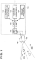
- FIG. 1 is a block diagram showing an example of the arrangement of a position and orientation measurement apparatus according to this embodiment.
- a position and orientation measurement apparatus 100 of this embodiment comprises an image input unit 110, data storage unit 120, subjective-view-index detection unit 130, additional subjective-view-index detection unit 140, and position and orientation calculation unit 150.
- the position and orientation measurement apparatus 100 is connected to a subjective-view camera 160 and additional subjective-view camera 170.
- the subjective-view camera 160 as an image capture device to be measured is fixed to, e.g., a head-mounted display (HMD) that the observer wears, and is used to capture an image of a physical space observed nearly from the viewpoint of the observer (subjective viewpoint).
- the additional subjective-view camera 170 as an additional image capture device has a known position and orientation relative to the subjective-view camera 160 and is set at a fixed position.
- the image capture range of the additional subjective-view camera 170 overlaps that of the subjective-view camera 160.
- the image capture range of the additional subjective-view camera 170 may or may not overlap that of the subjective-view camera 160.
- the subjective-view camera 160 and additional subjective-view camera 170 can be implemented by commercially available color video cameras.
- the image capture device to be measured need not always be a camera which captures an image of physical space observed from the viewpoint position of the observer.
- the additional subjective-view camera 170 has the same image resolution (the number of pixels of a captured image) as that of the subjective-view camera 160, and a narrower angle of view than that of the subjective-view camera 160. As a result, the additional subjective-view camera 170 can obtain an image with higher spatial resolution than the subjective-view camera 160. Therefore, indices that cannot be detected from an image captured by the subjective-view camera 160 can be detected from an image captured by the additional subjective-view camera 170. Since the image captured by the additional subjective-view camera 170 has higher spatial resolution, indices can be detected at higher positional precision than that using the image captured by the subjective-view camera 160.
- the image resolution of the additional subjective-view camera 170 may be increased.
- size and cost reductions of the additional subjective-view camera 170 can be attained by narrowing the angle of view without changing the image resolution. In this case, a time required for image processing can also be suppressed from being prolonged.
- Indices to be captured by the subjective-view camera 160 or additional subjective-view camera 170 are allocated at a plurality of positions on the physical space.
- subjective-view-indices are desirably set so that the total number of them observed on images captured by the subjective-view camera 160 and additional subjective-view camera 170 is always three or more when the subjective-view camera 160 moves within a measurement range.
- an image to be captured by the subjective-view camera 160 will be referred to as a subjective-view image
- an image to be captured by the additional subjective-view camera 170 will be referred to as an additional subjective-view image hereinafter.
- Fig. 1 four subjective-view-indices Q 1 , Q 2 , Q 3 , and Q 4 are allocated.
- the three subjective-view-indices Q 1 , Q 3 , and Q 4 are included in the field of view of the subjective-view camera 160, and the two subjective-view-indices Q 1 and Q 3 are included in the field of view of the additional subjective-view camera 170.
- the fields of view of the subjective-view camera 160 and additional subjective-view camera 170 commonly include only two subjective-view-indices Q 1 and Q 3. .
- the number of subjective-view-indices to be commonly included in the fields of view of these cameras is not limited and, for example, zero index may be included.
- the subjective-view-indices Q k may be circular markers having different colors or feature points such as natural features respectively having different texture features or the like.
- rectangular indices each formed of a rectangular unicolor region having a certain area may be used. That is, indices of arbitrary forms can be used as long as the image coordinates of a projected image on the captured image can be detected, and each index is identifiable by some method.
- the subjective-view-indices may be set by an operator or may use those having natural shapes, which are not set by the operator.
- the number of indices included in the field of view of the additional subjective-view camera 170, whose angle of view is narrower than that of the subjective-view camera 160 is normally smaller than that included in the field of view of the subjective-view camera 160, and may become zero in some cases. Even in such case, when three or more indices are observed on the subjective-view image, the position and orientation of the subjective-view camera 160 can be calculated.
- a method of calculating the position and orientation of the subjective-view camera 160 from the world coordinates of the subjective-view-indices and their coordinates in the subjective-view image is known in the field of phototopography and the like (for example, see R. M. Haralick, C. Lee, K. Ottenberg, and M.
- the position and orientation of the subjective-view camera 160 can be calculated.
- additional subjective-view-indices suited to the spatial resolution of the additional subjective-view camera 170 may be set independently of the subjective-view-indices.
- additional subjective-view-indices for example, circular markers having a smaller radius than the subjective-view-indices can be used.
- feature points such as natural features having texture features finer than the subjective-view-indices or the like may be used.
- rectangular indices having a smaller area than the subjective-view-indices may be used.
- the image input unit 110 converts the subjective-view image and additional subjective-view image input to the position and orientation measurement apparatus 100 into digital data, and saves them in the data storage unit 120.
- the subjective-view-index detection unit 130 reads out the subjective-view image from the data storage unit 120, and detects the image coordinates of the subjective-view-indices captured in the subjective-view image. For example, when the subjective-view-indices are markers respectively having different colors, regions corresponding to respective marker colors are detected from the image, and their barycentric positions are determined as the image coordinates of the respective subjective-view-indices.
- the image coordinates of the subjective-view-indices are detected by making template matching using template images of the respective subjective-view-indices, which are held in advance as known information.
- each rectangular index detected in this way is considered as four indices individually specified by four vertices in this embodiment.
- the subjective-view-index detection unit 130 outputs the detected image coordinates of the subjective-view-indices and identifiers of these indices to the data storage unit 120.
- N is the number of indices detected on the subjective-view image.
- the image coordinates of the detected index Q kn will be described as u Qkn .
- N 3
- the additional subjective-view-index detection unit 140 reads out the additional subjective-view image from the data storage unit 120, and detects the image coordinates of the subjective-view-indices captured in the additional subjective-view image, as in the subjective-view-index detection unit 130.
- the additional subjective-view-index detection unit 140 outputs the image coordinates of the detected subjective-view-indices and their identifiers to the data storage unit 120.
- M is the number of indices detected on the additional subjective-view image.
- the image coordinates of the detected index Q kn will be described as u Qkn .
- M 2
- the position and orientation calculation unit 150 acquires, from the data storage unit 120, a set of:
- the position and orientation calculation unit 150 calculates (estimates) the position and orientation of the subjective-view camera 160 based on these pieces of information.
- the calculated position and orientation are output to the data storage unit 120 in the form of a pair of a 3D vector x W C1 that represents the position, and a 3 ⁇ 3 matrix R WC1 that represents the orientation.
- the data storage unit 120 holds in advance data such as the world coordinates of the subjective-view-indices as known values, camera parameters of the subjective-view camera 160 and additional subjective-view camera 170, and the like. Also, the data storage unit 120 holds the subjective-view image and additional subjective-view image input from the image input unit 110, and the image coordinates and identifiers of the respective indices input from the subjective-view-index detection unit 130 and additional subjective-view-index detection unit 140. Furthermore, the data storage unit 120 holds the values of the position and orientation of the subjective-view camera 160 input from the position and orientation calculation unit 150.
- each of the image input unit 110, data storage unit 120, subjective-view-index detection unit 140, and additional subjective-view-index detection unit 150 shown in Fig. 1 can be configured by independent hardware.
- the functions of the respective units may be implemented by software when a CPU (not shown) executes programs.
- the CPU that implements the respective units by software may be a common CPU or a plurality of different CPUs.
- the functions of the respective units may be implemented by distributed processes of a plurality of computers connected via a network. Assume that this embodiment has a configuration in which the functions of the respective units (image input unit 110, data storage unit 120, subjective-view-index detection unit 140, and additional subjective-view-index detection unit 150) are implemented when one CPU executes programs.
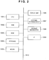
- Fig. 2 is a block diagram showing an example of the basic arrangement of a computer which can serve as the position and orientation measurement apparatus 100 of this embodiment.
- the image input unit 110, data storage unit 120, subjective-view-index detection unit 140, and additional subjective-view-index detection unit 150 are implemented by software by executing programs.
- a CPU 1001 controls the overall computer using programs and data stored in a RAM 1002 and ROM 1003.
- the CPU 1001 executes programs that implement the functions of the image input unit 110, data storage unit 120, subjective-view-index detection unit 140, and additional subjective-view-index detection unit 150, and serves as these units.
- the RAM 1002 comprises an area for temporarily storing programs and data loaded from an external storage device 1007 and storage medium drive 1008.
- the RAM 1002 also comprises a work area required for the CPU 1001 to execute various kinds of processing.
- the function of the data storage unit 120 is implemented by the RAM 1002.
- the ROM 1003 generally stores programs to be executed by the CPU 1001 upon starting up the computer, various setting data, and the like.
- a keyboard 1004 and mouse 1005 are input devices, and the operator can input various instructions to the computer using these input devices.
- the CPU 1001 detects inputs using these input devices.
- a display unit 1006 comprises a CRT monitor, LCD, or the like, and can display, e.g., messages and the like to be displayed for the position and orientation measurement of the subjective-view camera 160.
- the external storage device 1007 is a large-capacity storage device such as a hard disk or the like, and saves an OS (operating system), application programs, and the like.
- the external storage device 1007 stores pieces of information described as known information, which are loaded onto the RAM 1002 as needed.
- the storage medium drive 1008 reads out programs and data stored in a storage medium such as a CD-ROM, DVD-ROM, or the like in accordance with an instruction from the CPU 1001, and outputs them to the RAM 1002 and external storage device 1007.
- An I/F 1009 includes various interfaces used to connect external devices.
- the I/F 1009 includes interfaces used to connect the subjective-view camera 160 and additional subjective-view camera 170, and network interfaces used to output measurement results and the like. More specifically, the I/F 1009 includes an analog video interface, digital input/output interface (USB, IEEE1394, or the like), Ethernet® interface, and the like.
- Data input via the I/F 1009 are fetched on the RAM 1009. Some functions of the image input unit 110 are implemented by the I/F 1009.
- a bus 1010 connects the aforementioned units to allow intercommunications.
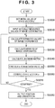
- Fig. 3 is a flowchart for explaining the operation of the position and orientation calculation unit 150 in the position and orientation measurement apparatus of this embodiment.
- the CPU 1001 serves as the position and orientation calculation unit 150 when it executes a program. Assume that the program code required for the CPU 101 to implement this processing has already been loaded onto the RAM 1002 prior to execution of the following processing. In this embodiment, the position and orientation of the subjective-view camera 160 are calculated by the numerical calculation method by repeated operations.
- the position and orientation calculation unit 150 internally expresses the position and orientation of the subjective-view camera 160 by three-valued vectors [x y z] T and [ ⁇ ⁇ ⁇ ] T .
- Various methods are available to express the orientation using three values.
- the orientation is expressed by a three-valued vector, so that the rotation angle is defined by the size of the vector and the rotation axis direction is defined by the direction of the vector.
- step S3000 the position and orientation calculation unit 150 sets appropriate initial values (estimated values of the position and orientation) in the state vector s. For example, upon calculating the position and orientation for each image frame of the subjective-view image and additional subjective-view image, s derived in the processing of the previous frame (time t k-1 ) can be used as the initial values. Also, predicted values based on a change in s within a predetermined nearest period may be used as the initial values.
- step S3010 the position and orientation calculation unit 150 acquires actually measured values u Qkn of the image coordinates and identifiers k n of respective subjective-view-indices Q kn detected by the subjective-view-index detection unit 130 from the data storage unit 120. Also, the position and orientation calculation unit 150 acquires actually measured values u Qkm of the image coordinates and identifiers k m of respective subjective-view-indices Q km detected by the additional subjective-view-index detection unit 140 from the data storage unit 120.
- step S3020 the position and orientation calculation unit 150 calculates estimated values u Qkn* and u Qkm* of the image coordinates for the subjective-view-indices Q kn detected from the subjective-view image and subjective-view-indices Q km detected from the additional subjective-view image.
- M C1C2 is calculated in advance based on the position and orientation (held in advance as known values in the data storage unit 120) of the additional subjective-view camera 170 on the subjective-view camera coordinate system.
- f C2 x and f C2 y are the focal lengths of the additional subjective-view camera 170 in the x- and y-axis directions, and are held in advance as known values in the data storage unit 120.
- step S3050 the position and orientation calculation unit 150 calculates a correction value ⁇ s of the state vector s based on the errors ⁇ u Qkn and ⁇ u Qkm calculated in steps S3030 and S3040, and the Jacobian matrices J us Qkn and J us Qkm .
- U is a 10-dimensional vector
- ⁇ is a matrix of 10 rows ⁇ 6 columns.
- the position and orientation calculation unit 150 increases a weight for the indices observed on the additional subjective-view image to improve the calculation precision of ⁇ s.
- angle of view (°) of subjective-view camera 160/angle of view (°) of additional subjective-view camera 170 ⁇
- step S3060 the position and orientation calculation unit 150 corrects the state vector s using the correction value ⁇ s calculated in step S3050 according to: s + ⁇ s ⁇ s and sets the obtained values as new estimated values of s.
- the position and orientation calculation unit 150 checks in step S3070 if the calculations converge using some criteria as to whether or not the error vector U or the correction value ⁇ s is smaller than a predetermined threshold. If the calculations do not converge, the unit 150 executes the processing in step S3020 and subsequent steps again using the state vector s after correction.
- the position and orientation calculation unit 150 outputs the obtained state vector s as information of the position and orientation of the subjective-view camera 160 to the data storage unit 120 in step S3080.
- the unit 150 outputs the information of the position and orientation in the form of a pair of the 3D vector x W C1 that represents the position, and the 3 ⁇ 3 matrix R WC1 (s) that represents the orientation.
- the position and orientation of the subjective-view camera 160 can be calculated with higher precision than a case of using only a subjective-view image or a case using a stereo camera having the same spatial resolution.
- the position and orientation calculation unit 150 repetitively executes processes in steps S3020 to S3060 (repeated operations) until the calculations are converted.
- first several repeated operations may use only the information of the subjective-view image, and repeated operations after the several operations may also use the information of the additional subjective-view image with high spatial resolution at the same time. In this way, the processing time can be shortened without deteriorating the precision of the finally calculated position and orientation of the subjective-view camera 160.
- the directions of the optical axes of the subjective-view camera 160 and additional subjective-view camera 170 nearly agree with each other, but they may be different.
- the positional precision in the optical axis direction of a camera is different from that in the in-frame direction. Therefore, for example, when the optical axis of the subjective-view camera 160 is set in a direction different from that of the additional subjective-view camera 170, the positional precisions in both the optical axis direction and in-frame direction can be improved by complementing the positional precisions with each other.
- the optical axis of the subjective-view camera 160 When the optical axis of the subjective-view camera 160 is set in a direction 90° different from that of the additional subjective-view camera 170, the optical axis direction of one camera agrees with the in-frame direction of the other camera. In this case, the positional precisions of the subjective-view camera 160 in both the optical axis direction and in-frame direction can be fully improved.
- a second camera with a higher spatial resolution is used together with a first camera as an object whose position and orientation are to be measured, and the position and orientation of the first camera are calculated using information of indices detected from the images captured by the two cameras. Since the information of each index detected from the image captured by the second camera has higher reliability than that of the index detected from the image captured by the first camera, the position and orientation with higher precision can be calculated.
- the first camera must capture a subjective-view image to be presented to the observer, and the angle of view and the like of the first camera cannot be changed like in an MR system in some cases.
- the second camera is added, and the position and orientation are calculated using the images captured by the two cameras, thus improving the position and orientation measurement precision of the first camera.
- a position and orientation measurement apparatus calculates the position and orientation of a subjective-view camera based on indices detected from an image captured by the subjective-view camera first. Then, the apparatus corrects the position and/or orientation based on indices detected from an image captured by an additional subjective-view camera with higher spatial resolution.
- the position and orientation measurement apparatus will be described below. Note that the arrangement of the position and orientation measurement apparatus according to this embodiment can be the same as that shown in Fig. 1 , except for the operation of the position and orientation calculation unit 150. Hence, only the operation of the position and orientation calculation unit 150 will be described below.
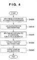
- Fig. 4 is a flowchart for explaining the operation of the position and orientation calculation unit 150 in the position and orientation measurement apparatus of this embodiment.
- the CPU 1001 serves as the position and orientation calculation unit 150 when it executes a program. Assume that the program code required for the CPU 101 to implement this processing has already been loaded onto the RAM 1002 prior to execution of the following processing.
- the position and orientation of the subjective-view camera 160 are calculated by the numerical calculation method by repeated operations.
- step S4000 the position and orientation calculation unit 150 acquires the image coordinates of the subjective-view-indices detected by the subjective-view-index detection unit 130 from the data storage unit 120.
- the position and orientation calculation unit 150 calculates the position and orientation of the subjective-view camera 160, which minimize the errors between the indices on the subjective-view image. More specifically, the unit 150 can calculate the position and orientation of the subjective-view camera 160 using a method described in, for example, R. M. Haralick, C. Lee, K. Ottenberg, and M. Nolle: Review and analysis of solutions of the three point perspective pose estimation problem, International Journal of Computer Vision, vol. 13, no. 3, pp. 331 - 356, 1994 ., and D. G. Lowe: Fitting parameterized three-dimensional models to images, IEEE Transactions on PAMI, vol. 13, no. 5, pp. 441 - 450, 1991 .
- step S4020 the position and orientation calculation unit 150 acquires the image coordinates of the subjective-view-indices detected by the additional subjective-view-index detection unit 140 from the data storage unit 120.
- the position and orientation calculation unit 150 corrects the orientation of the subjective-view camera 160 using the image coordinates of the subjective-view-indices detected by the additional subjective-view-index detection unit 140. Since the additional subjective-view camera 170 has higher spatial resolution than the subjective-view camera 160, the orientation of the subjective-view camera 160 can be calculated with high precision using the image coordinates of the subjective-view-indices detected by the additional subjective-view-index detection unit 140. On the other hand, the angle of view of the additional subjective-view camera 170 is narrower than the subjective-view camera 160, and is closer to an orthogonal projection. Therefore, a subjective-view image is more suitable in terms of use in the calculations of position.
- the orientation of the subjective-view camera 160 is corrected by a method described in method 3 of US 2002/0103617 A1 incorporated in the present specification by referring to its description contents.
- the image coordinates of the respective subjective-view-indices predicted based on the position and orientation of the subjective-view camera 160 calculated in step S4010 can be Pi in method 3 of US 2002/0103617 A1 .
- the image coordinates of the subjective-view-indices detected by the additional subjective-view-index detection unit 140 can be Qi of method 3 of US 2002/0103617 A1 .
- additional subjective-view-indices to be detected using the additional subjective-view camera 170 may be set independently of the subjective-view-indices.
- the additional subjective-view-indices can be circular markers having nearly identical colors, natural features such as edges and the like, textures having repetitive patterns, and the like. Even such indices can be used as additional subjective-view-indices as long as they can be identified using the rough position and orientation of the subjective-view camera 160 calculated in step S4010 in advance.
- both the position and orientation of the subjective-view camera 160 may be corrected by a method described in, e.g., US 2002/0103617 A1 .
- step S4040 the position and orientation calculation unit 150 outputs the information of the calculated position and orientation of the subjective-view camera 160 to the data storage unit 120 in the form of a pair of the 3D vector x W C1 that represents the position, and the 3 ⁇ 3 matrix R WC1 that represents the orientation.
- the position and orientation of the subjective-view camera 160 can be calculated with higher precision than the case in which the subjective-view image alone is used.
- the position and orientation of the subjective-view camera 160 calculated based on the indices detected from the subjective-view image are corrected based on the indices detected from the image captured by the additional subjective-view camera 170 with higher spatial resolution.
- the precision upon calculating the position and orientation of the subjective-view camera 160 can be improved.
- the position and orientation of the subjective-view camera are calculated based on the indices detected from the additional subjective-view image, and the position of the subjective-view camera may be corrected based on the indices detected from the subjective-view image by, e.g., the method described in US 2002/0103617 .
- the angle of view of the additional subjective-view camera may be larger than that of the subjective-view camera.
- the number of indices included in the field of view of the additional subjective-view camera increases, and the position and orientation of the subjective-view camera can be stably calculated.
- the position and orientation of the subjective-view camera may be calculated based on the indices detected from the additional subjective-view image, and the orientation of the subjective-view camera may then be corrected based on the indices detected from the subjective-view image.
- the position of the subjective-view camera can be calculated with higher precision when using the additional subjective-view image.
- the position and orientation of the subjective-view camera may be calculated based on the indices detected from the subjective-view image, and the position of the subjective-view camera may then be corrected based on the indices detected from the additional subjective-view image using a method described in, e.g., method 5 of US 2002/2103617 A1 .
- additional subjective-view image using a method described in, e.g., method 5 of US 2002/0103617 A1 .
- a sensor which measures the position, orientation, or information associated with their time derivatives may be located on the subjective-view camera to calculate the position and orientation of the subjective-view camera.
- the position and orientation of the subjective-view camera can be calculated by, e.g., a scheme described in US 2004/176925 A1 .
- the apparatus need only be set so that a total of at least two or more indices are always observed on the subjective-view image captured by the subjective-view camera, and the additional subjective-view image captured by the additional subjective-view camera.
- the position and orientation of the subjective-view camera can be calculated more stably than the case in which image information alone is used.
- the position and orientation of the subjective-view camera can be calculated by, e.g., a scheme described in Hirofumi Fujii, Masayuki Kanbara, Hidehiko Iwasa, Haruo Takemura, and Naokazu Yokoya, "A Registration Method Using Stereo Cameras with an Inertial Sensor for Augmented Reality", Technical Report of IEICE, PRMU 99-192 (Technical Report of IEICE, vol. 99, no. 574, pp. 1 - 8 ).
- the apparatus need only be set so that a total of at least two or more indices are always observed on the subjective-view image captured by the subjective-view camera, and the additional subjective-view image captured by the additional subjective-view camera.
- the position and orientation of the subjective-view camera can be calculated more stably than the case in which image information alone is used.
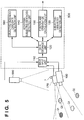
- FIG. 5 is a block diagram sowing the arrangement when an objective-view camera is added to the position and orientation measurement apparatus shown in Fig. 1 .
- An objective-view camera 590 has a known position and orientation.
- the objective-view camera captures an image of an objective-view-index P.
- the objective-view-index has a fixed position and orientation relative to the subjective-view camera 160.
- An objective-view-index detection unit 580 detects the image coordinate of the objective-view-index P from the image captured by the objective-view camera 590. By applying the image coordinate of the objective-view-index P to the scheme described in US 2004/176925 A1 , the position and orientation of the subjective-view camera 160 can be calculated. Note that the objective-view-index detection unit 580 can also be implemented by software when the CPU 1001 executes a program.
- the position and orientation of the subjective-view camera 160 can be stably calculated using the objective-view image.
- one additional subjective-view camera 170 is arranged.
- the number of additional subjective-view cameras 170 is not limited to one, but a plurality of cameras may be arranged.
- the position and orientation of the subjective-view camera 160 can be calculated by the same processing as in the first embodiment.
- the error vector U is expressed by a 2 (N+M 1 +M 2 +...+M A )-dimensional vector.
- the matrix ⁇ is expressed by a matrix of 2(N+M 1 +M 2 +...+M A ) rows ⁇ 6 columns.
- At least one of the additional subjective-view cameras 170 may be configured to have higher spatial resolution than the subjective-view camera 160, and at least one of the remaining additional subjective-view cameras 170 may be configured to have a larger angle of view than the subjective-view camera 160. With this configuration, the position and orientation of the subjective-view camera 160 can be stably calculated with high precision.
- the direction of the optical axis of at least one of the additional subjective-view cameras 170 may be configured to be different from that of the optical axis of at least one of the remaining additional subjective-view cameras 170.
- the position of the subjective-view camera 160 can be calculated with high precision. Therefore, by setting the optical axis of the subjective-view camera 160 and that of the additional subjective-view camera 170 with a larger angle of view in different directions, the positional precisions of the subjective-view camera 160 in both the optical axis direction and in-frame direction can be improved by complementing their positional precisions with each other.
- the additional subjective-view camera 170 having higher spatial resolution than the subjective-view camera 160 can detect highly reliable indices, the orientation of the subjective-view camera 160 can be calculated with high precision, as described in the above embodiments.
- a camera which captures light having a wavelength different from visible light may be used as the additional subjective-view camera 170.
- a camera which captures infrared rays may be used as the additional subjective-view camera 170, and indices that emit or reflect infrared rays may be used as additional subjective-view-indices.
- the indices can be detected more stably than the case in which a camera which captures visible light is used.
- a camera that captures infrared rays may be used as the subjective-view camera 160, and indices that emit or reflect infrared rays may be used as subjective-view-indices.
- cameras that capture infrared rays may be used as both the subjective-view camera 160 and additional subjective-view camera 170, and indices that emit or reflect infrared rays may be used as both subjective-view-indices and additional subjective-view-indices.
- the camera that captures light having a wavelength different from visible light is not limited to the camera that captures infrared rays, but a camera that captures ultraviolet rays or the like may be used. Furthermore, a camera that simultaneously captures light having a wavelength different from visible light, and the visible light may be used.
- a monochrome camera may be used as the additional subjective-view camera 170, and indices that do not include any color information may be used as additional subjective-view-indices.
- a processing time can be suppressed from being prolonged compared to a case using the color camera as the additional subjective-view camera 170.
- the correction value ⁇ s is calculated by the method expressed by equation (14) and the estimated value s is updated by substituting s by s + ⁇ s.
- the method of calculating s based on the matrix ⁇ and error vector U is not limited to such specific method.
- s may be calculated by combining, e.g., an LM method (Levenberg-Marquardt method) as a known iterative solving method of a nonlinear equation.
- a statistical method such as M-estimation or the like as a known robust estimation method may be combined. Any other numerical calculation methods may be combined.
- the aforementioned embodiments can be implemented by software by a computer (or a CPU, MPU, or the like) of a system or apparatus.
- a computer program itself supplied to in the computer to implement the aforementioned embodiments using the computer implements the present invention. That is, the computer program itself for implementing the functions of the aforementioned embodiments is one embodiment of the present invention.
- the form of the computer program which implements the aforementioned embodiments is not particularly limited as long as it is computer-readable.
- the program may adopt the forms of an object code, a program to be executed by an interpreter, script data to be supplied to an OS, and the like, but the present invention is not limited to them.
- the computer program which implements the aforementioned embodiments is supplied to the computer via a storage medium or wired/wireless communications.
- a storage medium for supplying the program for example, magnetic storage media such as a flexible disk, hard disk, magnetic tape, and the like, optical/magneto-optical storage media such as an MO, CD, DVD, and the like, a nonvolatile semiconductor memory, and so forth may be used.
- a server stores a data file (program file) that can be a computer program which forms the present invention.
- the program file may be either an executable format file or source codes.
- the program file is supplied by downloading to a client computer that has accessed the server.
- the program file may be segmented into a plurality of segment files, which may be allocated on different servers.
- the server which provides the program file for implementing the aforementioned embodiments to the client computer is also one embodiment of the present invention.
- a storage medium which stores the encrypted program which implements the aforementioned embodiments, may be delivered to the user, and key information required to decrypt the encrypted program may be supplied to the user who meets a predetermined condition, so as to allow to install the program on a computer of the user.
- the key information can be supplied to the user by making him or her download it from a home page via, e.g., the Internet.
- the computer program for implementing the aforementioned embodiments may use the functions of an OS which already runs on the computer.
- some functions of the computer program for implementing the aforementioned embodiments may be configured by firmware of an expansion board or the like attached to the computer, or may be executed by a CPU of the expansion board or the like.
- a position and orientation measurement apparatus has a subjective-view-index detection unit (130) which detects indices on a physical space from an image captured by a subjective-view camera (160), an additional subjective-view-index detection unit (140) which detects indices on the physical space from an image captured by an additional subjective-view camera (170) having a spatial resolution different from the subjective-view camera (160), and a position and orientation estimation unit (150) which calculates the position and orientation of the subjective-view camera (160) using information associated with the image coordinates of the detected indices.
Landscapes
- Physics & Mathematics (AREA)
- General Physics & Mathematics (AREA)
- Engineering & Computer Science (AREA)
- Computer Vision & Pattern Recognition (AREA)
- Theoretical Computer Science (AREA)
- Length Measuring Devices By Optical Means (AREA)
- Image Processing (AREA)
- Image Analysis (AREA)
Description
- The present invention relates to a method and apparatus for measuring the position and orientation of an object and, more particularly, those of an image capture device.
- Measurement of the position and orientation of an image capture unit (to be referred to as a camera hereinafter as needed) such as a camera or the like used to capture an image of a physical space is required in, e.g., a mixed reality system that integrally presents the physical space and a virtual space.
- Japanese Patent Laid-Open No.
11-084307 2000-041173 - As disclosed in Kato, Billinghurst, Asano, and Tachibana: Augmented Reality System and its Calibration based on Marker Tracking, Journal of the Virtual Reality Society of Japan, vol. 4, no. 4, pp. 607 - 616, Dec. 1999., and X. Zhang, S. Fronz, and N. Navab: Visual marker detection and decoding in AR systems: A comparative study, Proc. of International Symposium on Mixed and Augmented Reality (ISMAR'02), 2002., a method for estimating the position and orientation of a camera based on information of markers captured by a camera without using any position and orientation sensor is known. In these references, square indices are used, and the position and orientation of the camera are estimated based on the coordinates of four vertices of each square. However, since a square is rotation symmetrical every 90° with respect to an axis that passes through its central point (the intersection of diagonal lines) and is perpendicular to its plane as a rotation axis, the directionality (top, bottom, right, and left) cannot be determined from only the vertex coordinates in the image. For this reason, a graphic image having directionality or the like is drawn inside a square index to determine the top, bottom, right, and left from an image obtained by capturing the index. Furthermore, when a plurality of indices are used, since they need be identified based on only the image captured by the camera, graphic information such as unique patterns, symbols, or the like, which are different for respective indices, is drawn inside each index.
- As disclosed in
US 2004/176925 A1 which is to be incorporated in the present specification by referring to its description contents, a method of enhancing the estimation precision and stability of the position and orientation of a camera by capturing indices using a stereo camera so as to increase the total number of indices to be detected compared to a case using only one camera is known. InUS 2004/176925 A1 , respective cameras which form the stereo camera have the same resolution and angle of view. The optical axes of the respective cameras agree with nearly the same direction. - Japanese Patent Laid-Open No.
2004-205711 2004-205711 - On the other hand, Shigezumi Kuwajima: 2Way Stereo System miniBEE, the Journal of Virtual Reality Society of Japan, vol. 10, no. 3, pp. 50 - 51, Sep. 2005. discloses an apparatus which performs three-dimensional (3D) measurement of an object by mutually complementing the measurement results of two different 2-lens stereo cameras for short and long distances. In the apparatus described in this reference, the baseline lengths and focal lengths are selected in correspondence with the short and long distances, and objects at the short and long distances can be simultaneously measured.
- In the method of
Related Art 1, a small circular, sheet-like object with a specific color can be allocated as an index. In this case, the index has information including a 3D position (coordinates) and color. The 3D position of the index is projected onto the image plane of the camera using the measurement values of the position and orientation sensor, while color region detection processing for detecting the color of the index from an image is executed, thus calculating the barycentric position of the color region in the image. The 3D position of the index projected onto the image lane is compared with the barycentric position of the color region calculated from the image, and an identical index is determined when these positions are close to each other, thereby identifying the index in the image. - In
Related Art 1, the camera whose position and orientation are to be measured is a device for capturing an image to be presented to the observer. Therefore, the resolution, angle of view, orientation, and the like of the camera cannot be freely changed to suitthe detection of an index. That is, the measurement precision of the position and orientation of the camera is determined depending on the spatial resolution of the camera which is not always optimal to the detection of the index. - On the other hand, the method of measuring the position and orientation of a camera using an index like a square marker, which is used in
Related Art 2 and an image of which gives many kinds of information such as vertices, drawn pattern, and the like can be detected is available. InRelated Art 2, since each individual marker need be identified from the image alone without using any position and orientation sensor, the index must include code information, symbol information which can serve as a template, and the like. -
Figs. 6A to 6C show examples of practical square markers used in the system described in the reference presented as an example ofRelated Art 2. - Since an index having such a complicated feature must be detected from a captured image, it cannot often be recognized unless it is captured to occupy a sufficiently large area in the captured image frame. In other words, either a broad region on the physical space must be assured to allocate the index, or the camera must sufficiently come near the index. That is, the index allocation conditions are strict.
- In
Related Art 2 as well, the camera whose position and orientation are to be measured is a device used to capture an image to be presented to the observer, as inRelated Art 1. Therefore, the measurement precision of the position and orientation of the camera is determined depending on the spatial resolution of the camera which is not always optimal to the detection of the index, as inRelated Art 1. - In Related Art 3 as well, the cameras which form the stereo camera are devices used to capture an image to be presented to the observer. Therefore, the measurement precision of the position and orientation of the camera and the detectable index size are determined depending on the spatial resolution of the camera which is not always optimal to the detection of the index, as in
Related Arts - In Related Art 4, upon calculating the position and orientation of the camera, the plurality of cameras having different angles of view are not used simultaneously, but the camera of one angle of view is used. Therefore, the estimation precision of the position and orientation of the camera is lower than that using a plurality of cameras.
- On the other hand, in Related Art 5, the plurality of cameras having different angles of view are used at the same time, but this technique is limited to a method that performs stereo measurement using the cameras of the same angle of view and then combines a plurality of stereo measurement results. Upon applying the scheme of Related Art 5, four or more cameras are required.
- The present invention has been made to solve the problems of these related arts. The present invention enhances the measurement precision and/or stability in a position measurement method and apparatus which measure the position and orientation of an image capture device using an index on the physical space.
- The present invention in its first aspect provides a position and orientation measurement method as specified in
claims 1 to 12. - The present invention in its second aspect provides a position and orientation measurement apparatus as specified in claim 13. The present invention in its third aspect provides a computer-readable recording medium as specified in claim 14.
- Further features of the present invention will become apparent from the following description of exemplary embodiments with reference to the attached drawings.
-
-
Fig. 1 is a block diagram showing an example of the arrangement of a position and orientation measurement apparatus according to the first embodiment of the present invention; -
Fig. 2 is a block diagram showing an example of the basic arrangement of a computer which can serve as a position andorientation measurement apparatus 100 according to the embodiment of the present invention; -
Fig. 3 is a flowchart for explaining the operation of a position andorientation calculation unit 150 in the position and orientation measurement apparatus of the first embodiment; -
Fig. 4 is a flowchart for explaining the operation of a position andorientation calculation unit 150 in the position and orientation measurement apparatus of the second embodiment; -
Fig. 5 is a block diagram showing the arrangement when an objective-view camera is additionally connected to the position and orientation measurement apparatus shown inFig. 1 ; and -
Figs. 6A to 6C show examples of indices used in the related arts. - Preferred embodiments of the present invention will now be described in detail in accordance with the accompanying drawings.
- A position and orientation measurement apparatus according to the first embodiment of the present invention calculates the position and orientation of a subjective-view camera based on indices detected from images captured by the subjective-view camera and an objective-view camera.
-
Fig. 1 is a block diagram showing an example of the arrangement of a position and orientation measurement apparatus according to this embodiment. A position andorientation measurement apparatus 100 of this embodiment comprises animage input unit 110,data storage unit 120, subjective-view-index detection unit 130, additional subjective-view-index detection unit 140, and position andorientation calculation unit 150. The position andorientation measurement apparatus 100 is connected to a subjective-view camera 160 and additional subjective-view camera 170. - In this embodiment, assume that the subjective-
view camera 160 as an image capture device to be measured is fixed to, e.g., a head-mounted display (HMD) that the observer wears, and is used to capture an image of a physical space observed nearly from the viewpoint of the observer (subjective viewpoint). The additional subjective-view camera 170 as an additional image capture device has a known position and orientation relative to the subjective-view camera 160 and is set at a fixed position. The image capture range of the additional subjective-view camera 170 overlaps that of the subjective-view camera 160. Note that the image capture range of the additional subjective-view camera 170 may or may not overlap that of the subjective-view camera 160. The subjective-view camera 160 and additional subjective-view camera 170 can be implemented by commercially available color video cameras. - Note that this embodiment uses the "subjective-view" camera for the sake of convenience. However, the image capture device to be measured need not always be a camera which captures an image of physical space observed from the viewpoint position of the observer.
- The additional subjective-
view camera 170 has the same image resolution (the number of pixels of a captured image) as that of the subjective-view camera 160, and a narrower angle of view than that of the subjective-view camera 160. As a result, the additional subjective-view camera 170 can obtain an image with higher spatial resolution than the subjective-view camera 160. Therefore, indices that cannot be detected from an image captured by the subjective-view camera 160 can be detected from an image captured by the additional subjective-view camera 170. Since the image captured by the additional subjective-view camera 170 has higher spatial resolution, indices can be detected at higher positional precision than that using the image captured by the subjective-view camera 160. - In order to enhance the spatial resolution of the additional subjective-
view camera 170, the image resolution of the additional subjective-view camera 170 may be increased. However, size and cost reductions of the additional subjective-view camera 170 can be attained by narrowing the angle of view without changing the image resolution. In this case, a time required for image processing can also be suppressed from being prolonged. - Indices (to be referred to as subjective-view-indices) to be captured by the subjective-
view camera 160 or additional subjective-view camera 170 are allocated at a plurality of positions on the physical space. Each subjective-view-index Qk (k = 1,..., KQ) has a known position xW Qk on a world coordinate system. Note that the world coordinate system is specified by defining one point on the physical space as an origin, and three orthogonal axes as X-, Y, and Z-axes. - These subjective-view-indices are desirably set so that the total number of them observed on images captured by the subjective-
view camera 160 and additional subjective-view camera 170 is always three or more when the subjective-view camera 160 moves within a measurement range. Note that an image to be captured by the subjective-view camera 160 will be referred to as a subjective-view image, and an image to be captured by the additional subjective-view camera 170 will be referred to as an additional subjective-view image hereinafter. - In the example shown in
Fig. 1 , four subjective-view-indices Q1, Q2, Q3, and Q4 are allocated. The three subjective-view-indices Q1, Q3, and Q4 are included in the field of view of the subjective-view camera 160, and the two subjective-view-indices Q1 and Q3 are included in the field of view of the additional subjective-view camera 170. - In
Fig. 1 , the fields of view of the subjective-view camera 160 and additional subjective-view camera 170 commonly include only two subjective-view-indices Q1 and Q3.. However, the number of subjective-view-indices to be commonly included in the fields of view of these cameras is not limited and, for example, zero index may be included. - The subjective-view-indices Qk may be circular markers having different colors or feature points such as natural features respectively having different texture features or the like. Alternatively, rectangular indices each formed of a rectangular unicolor region having a certain area may be used. That is, indices of arbitrary forms can be used as long as the image coordinates of a projected image on the captured image can be detected, and each index is identifiable by some method. The subjective-view-indices may be set by an operator or may use those having natural shapes, which are not set by the operator.
- Note that the number of indices included in the field of view of the additional subjective-
view camera 170, whose angle of view is narrower than that of the subjective-view camera 160 is normally smaller than that included in the field of view of the subjective-view camera 160, and may become zero in some cases. Even in such case, when three or more indices are observed on the subjective-view image, the position and orientation of the subjective-view camera 160 can be calculated. A method of calculating the position and orientation of the subjective-view camera 160 from the world coordinates of the subjective-view-indices and their coordinates in the subjective-view image is known in the field of phototopography and the like (for example, see R. M. Haralick, C. Lee, K. Ottenberg, and M. Nolle: Review and analysis of solutions of the three point perspective pose estimation problem, International Journal of Computer Vision, vol. 13, no. 3, pp. 331 - 356, 1994., and D. G. Lowe: Fitting parameterized three-dimensional models to images, IEEE Transactions on PAMI, vol. 13, no. 5, pp. 441 - 450, 1991.) Hence, a detailed description thereof will not be given. - Conversely, even when the number of indices included in the field of view of the subjective-
view camera 160 is zero, if three or more indices are included in the field of view of the additional subjective-view camera 170, the position and orientation of the subjective-view camera 160 can be calculated. - On the other hand, even an index with a size which cannot be detected from the subjective-view image may be detected from the additional subjective-view image captured by the additional subjective-
view camera 170 with a higher spatial resolution. Therefore, additional subjective-view-indices suited to the spatial resolution of the additional subjective-view camera 170 may be set independently of the subjective-view-indices. As the additional subjective-view-indices, for example, circular markers having a smaller radius than the subjective-view-indices can be used. Alternatively, feature points such as natural features having texture features finer than the subjective-view-indices or the like may be used. Also, rectangular indices having a smaller area than the subjective-view-indices may be used. - The
image input unit 110 converts the subjective-view image and additional subjective-view image input to the position andorientation measurement apparatus 100 into digital data, and saves them in thedata storage unit 120. - The subjective-view-
index detection unit 130 reads out the subjective-view image from thedata storage unit 120, and detects the image coordinates of the subjective-view-indices captured in the subjective-view image. For example, when the subjective-view-indices are markers respectively having different colors, regions corresponding to respective marker colors are detected from the image, and their barycentric positions are determined as the image coordinates of the respective subjective-view-indices. - When the subjective-view-indices are feature points having different texture features, the image coordinates of the subjective-view-indices are detected by making template matching using template images of the respective subjective-view-indices, which are held in advance as known information.
- When the rectangular indices are used, the image undergoes binarization processing and labeling to detect regions each formed of four straight lines as index candidates. Furthermore, it is checked if each candidate region includes a specific pattern to eliminate detection errors, and to acquire an identifier of that index. Note that each rectangular index detected in this way is considered as four indices individually specified by four vertices in this embodiment.
- The subjective-view-
index detection unit 130 outputs the detected image coordinates of the subjective-view-indices and identifiers of these indices to thedata storage unit 120. In the following description, an index detected on the subjective-view image will be described as Qkn using an identifier n (n = 1,..., N) appended to each individual detected index. Note that N is the number of indices detected on the subjective-view image. Also, the image coordinates of the detected index Qkn will be described as uQkn. - For example, in case of
Fig. 1 , N = 3, and identifiers k1 = 1, k2 = 3, and k3 = 4 of the indices and corresponding image coordinates uQk1, uQk2, and uQk3 are output. - The additional subjective-view-
index detection unit 140 reads out the additional subjective-view image from thedata storage unit 120, and detects the image coordinates of the subjective-view-indices captured in the additional subjective-view image, as in the subjective-view-index detection unit 130. - Furthermore, the additional subjective-view-
index detection unit 140 outputs the image coordinates of the detected subjective-view-indices and their identifiers to thedata storage unit 120. In the following description, an index detected on the additional subjective-view image will be described as Qkm using an identifier m (m = 1,..., M) appended to each individual detected index. Note that M is the number of indices detected on the additional subjective-view image. Also, the image coordinates of the detected index Qkn will be described as uQkn. For example, in case ofFig. 1 , M = 2, and identifiers k1 = 1 and k2 = 3 of the indices and corresponding image coordinates uQk1 and uQk2 are output. - The position and
orientation calculation unit 150 acquires, from thedata storage unit 120, a set of: - the image coordinates uQkn of the respective subjective-view-indices detected by the subjective-view-
index detection unit 130; - the image coordinates uQkm of the respective subjective-view-indices detected by the additional subjective-view-
index detection unit 140; and - the world coordinates xW Qk of the subjective-view-indices held in advance as known information.
- Then, the position and
orientation calculation unit 150 calculates (estimates) the position and orientation of the subjective-view camera 160 based on these pieces of information. The calculated position and orientation are output to thedata storage unit 120 in the form of a pair of a 3D vector xW C1 that represents the position, and a 3 × 3 matrix RWC1 that represents the orientation. - The
data storage unit 120 holds in advance data such as the world coordinates of the subjective-view-indices as known values, camera parameters of the subjective-view camera 160 and additional subjective-view camera 170, and the like. Also, thedata storage unit 120 holds the subjective-view image and additional subjective-view image input from theimage input unit 110, and the image coordinates and identifiers of the respective indices input from the subjective-view-index detection unit 130 and additional subjective-view-index detection unit 140. Furthermore, thedata storage unit 120 holds the values of the position and orientation of the subjective-view camera 160 input from the position andorientation calculation unit 150. - Note that each of the
image input unit 110,data storage unit 120, subjective-view-index detection unit 140, and additional subjective-view-index detection unit 150 shown inFig. 1 can be configured by independent hardware. Alternatively, the functions of the respective units may be implemented by software when a CPU (not shown) executes programs. The CPU that implements the respective units by software may be a common CPU or a plurality of different CPUs. The functions of the respective units may be implemented by distributed processes of a plurality of computers connected via a network. Assume that this embodiment has a configuration in which the functions of the respective units (image input unit 110,data storage unit 120, subjective-view-index detection unit 140, and additional subjective-view-index detection unit 150) are implemented when one CPU executes programs. -
Fig. 2 is a block diagram showing an example of the basic arrangement of a computer which can serve as the position andorientation measurement apparatus 100 of this embodiment. - As described above, in this embodiment, the
image input unit 110,data storage unit 120, subjective-view-index detection unit 140, and additional subjective-view-index detection unit 150 are implemented by software by executing programs. - A
CPU 1001 controls the overall computer using programs and data stored in aRAM 1002 andROM 1003. TheCPU 1001 executes programs that implement the functions of theimage input unit 110,data storage unit 120, subjective-view-index detection unit 140, and additional subjective-view-index detection unit 150, and serves as these units. - The
RAM 1002 comprises an area for temporarily storing programs and data loaded from anexternal storage device 1007 andstorage medium drive 1008. TheRAM 1002 also comprises a work area required for theCPU 1001 to execute various kinds of processing. In this embodiment, the function of thedata storage unit 120 is implemented by theRAM 1002. - The
ROM 1003 generally stores programs to be executed by theCPU 1001 upon starting up the computer, various setting data, and the like. Akeyboard 1004 andmouse 1005 are input devices, and the operator can input various instructions to the computer using these input devices. TheCPU 1001 detects inputs using these input devices. - A
display unit 1006 comprises a CRT monitor, LCD, or the like, and can display, e.g., messages and the like to be displayed for the position and orientation measurement of the subjective-view camera 160. - The
external storage device 1007 is a large-capacity storage device such as a hard disk or the like, and saves an OS (operating system), application programs, and the like. In this embodiment, theexternal storage device 1007 stores pieces of information described as known information, which are loaded onto theRAM 1002 as needed. - The
storage medium drive 1008 reads out programs and data stored in a storage medium such as a CD-ROM, DVD-ROM, or the like in accordance with an instruction from theCPU 1001, and outputs them to theRAM 1002 andexternal storage device 1007. - An I/
F 1009 includes various interfaces used to connect external devices. In this embodiment, the I/F 1009 includes interfaces used to connect the subjective-view camera 160 and additional subjective-view camera 170, and network interfaces used to output measurement results and the like. More specifically, the I/F 1009 includes an analog video interface, digital input/output interface (USB, IEEE1394, or the like), Ethernet® interface, and the like. - Data input via the I/
F 1009 are fetched on theRAM 1009. Some functions of theimage input unit 110 are implemented by the I/F 1009. - A
bus 1010 connects the aforementioned units to allow intercommunications. -
Fig. 3 is a flowchart for explaining the operation of the position andorientation calculation unit 150 in the position and orientation measurement apparatus of this embodiment. - As described above, the
CPU 1001 serves as the position andorientation calculation unit 150 when it executes a program. Assume that the program code required for the CPU 101 to implement this processing has already been loaded onto theRAM 1002 prior to execution of the following processing. In this embodiment, the position and orientation of the subjective-view camera 160 are calculated by the numerical calculation method by repeated operations. - The position and
orientation calculation unit 150 internally expresses the position and orientation of the subjective-view camera 160 by three-valued vectors [x y z]T and [ξ ψ ζ]T. Various methods are available to express the orientation using three values. In this embodiment, the orientation is expressed by a three-valued vector, so that the rotation angle is defined by the size of the vector and the rotation axis direction is defined by the direction of the vector. At this time, unknown parameters to be calculated are described by a six-valued state vector s = [x y z ξ ψ ζ]T. - In step S3000, the position and
orientation calculation unit 150 sets appropriate initial values (estimated values of the position and orientation) in the state vector s. For example, upon calculating the position and orientation for each image frame of the subjective-view image and additional subjective-view image, s derived in the processing of the previous frame (time tk-1) can be used as the initial values. Also, predicted values based on a change in s within a predetermined nearest period may be used as the initial values. - In step S3010, the position and
orientation calculation unit 150 acquires actually measured values uQkn of the image coordinates and identifiers kn of respective subjective-view-indices Qkn detected by the subjective-view-index detection unit 130 from thedata storage unit 120. Also, the position andorientation calculation unit 150 acquires actually measured values uQkm of the image coordinates and identifiers km of respective subjective-view-indices Qkm detected by the additional subjective-view-index detection unit 140 from thedata storage unit 120. - In step S3020, the position and
orientation calculation unit 150 calculates estimated values uQkn* and uQkm* of the image coordinates for the subjective-view-indices Qkn detected from the subjective-view image and subjective-view-indices Qkm detected from the additional subjective-view image. - Each uQkn* is calculated based on the world coordinates xW Qkn of each index Qkn which is held in advance as known information in the
data storage unit 120 and a function of the current state vector s:
- Also, each uQkm* is calculated based on the world coordinates xW Qkm of each index Qkm which is held in advance as known information in the
data storage unit 120 and a function of the current state vector s:
- More specifically, the function FC1() is configured by an equation which is required to calculate the subjective-view camera coordinates (a coordinate system specified by defining one point on the subjective-
view camera 160 as an origin, and defining three orthogonal axes as X-, Y-, and Z-axes) xC1 Qkn of the index of interest from xW Qkn and s, and is described by:

view camera 160 in the x- and y-axis directions, and are held in advance as known values in thedata storage unit 120. Also, MWC1(s) is a modeling transformation matrix defined by s (i.e., a matrix for transforming the coordinates on the subjective-view camera coordinate system into those on the world coordinate system) and is defined by:

- On the other hand, the function FC2() is configured by an equation which is required to calculate additional subjective-view camera coordinates (a coordinate system specified by defining one point on the additional subjective-
view camera 170 as an origin, and defining three orthogonal axes as X-, Y-, and Z-axes) xC2 Qkm of the index of interest from xW Qkm and s, and is described by:

view camera 170 on the subjective-view camera coordinate system. fC2 x and fC2 y are the focal lengths of the additional subjective-view camera 170 in the x- and y-axis directions, and are held in advance as known values in thedata storage unit 120. - In step S3030, the position and
orientation calculation unit 150 calculates errors ΔuQkn between estimated values uQkn* and actually measured values uQkn of the image coordinates for respective subjective-view-indices Qkn by:
- Also, the position and
orientation calculation unit 150 calculates errors ΔuQkm between estimated values uQkm* and actually measured values uQkm of the image coordinates for respective additional subjective-view-indices Qkm by:
- In step S3040, the position and
orientation calculation unit 150 calculates a Jacobian matrix Jus QKn (= ∂uQkn/∂s) of 2 rows × 6 columns having, as respective elements, solutions obtained by partially differentiating the function FC1() given by equation (1) by the respective elements of the state vector s. Also, the position andorientation calculation unit 150 calculates a Jacobian matrix Jus QKm (= ∂uQkm/∂s) of 2 rows × 6 columns having, as respective elements, solutions obtained by partially differentiating the function FC2() given by equation (2) by the respective elements of the state vector s. - More specifically, the position and
orientation calculation unit 150 calculates a Jacobian matrix Jux Qkn (= ∂uQkn/∂xQkn) of 2 rows × 3 columns having, as respective elements, solutions obtained by partially differentiating the right-hand side of equation (4) by the elements of the subjective-view camera coordinates xC1 Qkn, and a Jacobian matrix Jxs Qkn (= ∂xQkn/∂s) of 3 rows × 6 columns having, as respective elements, solutions obtained by partially differentiating the right-hand side of equation (3) by the elements of the vector s, and calculates Jus Qkn by:
- Also, the position and
orientation calculation unit 150 calculates a Jacobian matrix Jux Qkm (= ∂uQkm/∂xQkm) of 2 rows × 3 columns having, as respective elements, solutions obtained by partially differentiating the right-hand side of equation (7) by the elements of the additional subjective-view camera coordinates xC2 Qkm, and a Jacobian matrix Jxs Qkm (= ∂xQkm/∂s) of 3 rows × 6 columns having, as respective elements, solutions obtained by partially differentiating the right-hand side of equation (6) by the elements of the vector s, and calculates Jus Qkm by:
- In step S3050, the position and
orientation calculation unit 150 calculates a correction value Δs of the state vector s based on the errors ΔuQkn and ΔuQkm calculated in steps S3030 and S3040, and the Jacobian matrices Jus Qkn and Jus Qkm. More specifically, theunit 150 generates a 2(N+M)-dimensional error vector which is defined by vertically arranging errors ΔuQkn and ΔuQkm and is described by:

unit 150 calculates Δs using a pseudo inverse matrix Θ+ of Θ as:
Fig. 1 , since N = 3 and M = 2, U is a 10-dimensional vector, and Θ is a matrix of 10 rows × 6 columns. - Since the additional subjective-
view camera 170 has higher spatial resolution than the subjective-view camera 160, indices observed on the additional subjective-view image have higher reliability than those observed on the subjective-view image. Hence, the position andorientation calculation unit 150 increases a weight for the indices observed on the additional subjective-view image to improve the calculation precision of Δs. That is, theunit 150 calculates the pseudo inverse matrix Θ+ in equation (14) as:

- For example, when
angle of view (°) of subjective-view camera 160/angle of view (°) of additional subjective-view camera 170 = α,
wn and wm can be defined to meet:
- In step S3060, the position and
orientation calculation unit 150 corrects the state vector s using the correction value Δs calculated in step S3050 according to:
- The position and
orientation calculation unit 150 checks in step S3070 if the calculations converge using some criteria as to whether or not the error vector U or the correction value Δs is smaller than a predetermined threshold. If the calculations do not converge, theunit 150 executes the processing in step S3020 and subsequent steps again using the state vector s after correction. - If it is determined in step S3070 that the calculations converge, the position and
orientation calculation unit 150 outputs the obtained state vector s as information of the position and orientation of the subjective-view camera 160 to thedata storage unit 120 in step S3080. Theunit 150 outputs the information of the position and orientation in the form of a pair of the 3D vector xW C1 that represents the position, and the 3 × 3 matrix RWC1(s) that represents the orientation. - With the aforementioned processing, the position and orientation of the subjective-
view camera 160 can be calculated with higher precision than a case of using only a subjective-view image or a case using a stereo camera having the same spatial resolution. - In this embodiment, the position and
orientation calculation unit 150 repetitively executes processes in steps S3020 to S3060 (repeated operations) until the calculations are converted. In the repetitive processing, first several repeated operations may use only the information of the subjective-view image, and repeated operations after the several operations may also use the information of the additional subjective-view image with high spatial resolution at the same time. In this way, the processing time can be shortened without deteriorating the precision of the finally calculated position and orientation of the subjective-view camera 160. - In this embodiment, the directions of the optical axes of the subjective-
view camera 160 and additional subjective-view camera 170 nearly agree with each other, but they may be different. In general, the positional precision in the optical axis direction of a camera is different from that in the in-frame direction. Therefore, for example, when the optical axis of the subjective-view camera 160 is set in a direction different from that of the additional subjective-view camera 170, the positional precisions in both the optical axis direction and in-frame direction can be improved by complementing the positional precisions with each other. When the optical axis of the subjective-view camera 160 is set in a direction 90° different from that of the additional subjective-view camera 170, the optical axis direction of one camera agrees with the in-frame direction of the other camera. In this case, the positional precisions of the subjective-view camera 160 in both the optical axis direction and in-frame direction can be fully improved. - As described above, according to this embodiment, a second camera with a higher spatial resolution is used together with a first camera as an object whose position and orientation are to be measured, and the position and orientation of the first camera are calculated using information of indices detected from the images captured by the two cameras. Since the information of each index detected from the image captured by the second camera has higher reliability than that of the index detected from the image captured by the first camera, the position and orientation with higher precision can be calculated.
- For example, the first camera must capture a subjective-view image to be presented to the observer, and the angle of view and the like of the first camera cannot be changed like in an MR system in some cases. Even in such case, according to this embodiment, the second camera is added, and the position and orientation are calculated using the images captured by the two cameras, thus improving the position and orientation measurement precision of the first camera.
- The second embodiment of the present invention will be described hereinafter.
- A position and orientation measurement apparatus according to this embodiment calculates the position and orientation of a subjective-view camera based on indices detected from an image captured by the subjective-view camera first. Then, the apparatus corrects the position and/or orientation based on indices detected from an image captured by an additional subjective-view camera with higher spatial resolution.
- The position and orientation measurement apparatus according to this embodiment will be described below. Note that the arrangement of the position and orientation measurement apparatus according to this embodiment can be the same as that shown in
Fig. 1 , except for the operation of the position andorientation calculation unit 150. Hence, only the operation of the position andorientation calculation unit 150 will be described below. -
Fig. 4 is a flowchart for explaining the operation of the position andorientation calculation unit 150 in the position and orientation measurement apparatus of this embodiment. In this embodiment as well, theCPU 1001 serves as the position andorientation calculation unit 150 when it executes a program. Assume that the program code required for the CPU 101 to implement this processing has already been loaded onto theRAM 1002 prior to execution of the following processing. In this embodiment, the position and orientation of the subjective-view camera 160 are calculated by the numerical calculation method by repeated operations. - In step S4000, the position and
orientation calculation unit 150 acquires the image coordinates of the subjective-view-indices detected by the subjective-view-index detection unit 130 from thedata storage unit 120. - In step S4010, the position and
orientation calculation unit 150 calculates the position and orientation of the subjective-view camera 160, which minimize the errors between the indices on the subjective-view image. More specifically, theunit 150 can calculate the position and orientation of the subjective-view camera 160 using a method described in, for example, R. M. Haralick, C. Lee, K. Ottenberg, and M. Nolle: Review and analysis of solutions of the three point perspective pose estimation problem, International Journal of Computer Vision, vol. 13, no. 3, pp. 331 - 356, 1994., and D. G. Lowe: Fitting parameterized three-dimensional models to images, IEEE Transactions on PAMI, vol. 13, no. 5, pp. 441 - 450, 1991. - In step S4020, the position and
orientation calculation unit 150 acquires the image coordinates of the subjective-view-indices detected by the additional subjective-view-index detection unit 140 from thedata storage unit 120. - In step S4030, the position and
orientation calculation unit 150 corrects the orientation of the subjective-view camera 160 using the image coordinates of the subjective-view-indices detected by the additional subjective-view-index detection unit 140. Since the additional subjective-view camera 170 has higher spatial resolution than the subjective-view camera 160, the orientation of the subjective-view camera 160 can be calculated with high precision using the image coordinates of the subjective-view-indices detected by the additional subjective-view-index detection unit 140. On the other hand, the angle of view of the additional subjective-view camera 170 is narrower than the subjective-view camera 160, and is closer to an orthogonal projection. Therefore, a subjective-view image is more suitable in terms of use in the calculations of position. For this reason, in this embodiment, only the orientation of the subjective-view camera 160 is corrected by a method described in method 3 ofUS 2002/0103617 A1 incorporated in the present specification by referring to its description contents. Note that the image coordinates of the respective subjective-view-indices predicted based on the position and orientation of the subjective-view camera 160 calculated in step S4010 can be Pi in method 3 ofUS 2002/0103617 A1 . Also, the image coordinates of the subjective-view-indices detected by the additional subjective-view-index detection unit 140 can be Qi of method 3 ofUS 2002/0103617 A1 . - Note that additional subjective-view-indices to be detected using the additional subjective-
view camera 170 may be set independently of the subjective-view-indices. For example, in this embodiment, even indices each of which cannot be individually identified can be used as additional subjective-view-indices. That is, the additional subjective-view-indices can be circular markers having nearly identical colors, natural features such as edges and the like, textures having repetitive patterns, and the like. Even such indices can be used as additional subjective-view-indices as long as they can be identified using the rough position and orientation of the subjective-view camera 160 calculated in step S4010 in advance. - When the difference between the angles of view of the subjective-
view camera 160 and additional subjective-view camera 170 is smaller than a threshold, both the position and orientation of the subjective-view camera 160 may be corrected by a method described in, e.g.,US 2002/0103617 A1 . - In step S4040, the position and
orientation calculation unit 150 outputs the information of the calculated position and orientation of the subjective-view camera 160 to thedata storage unit 120 in the form of a pair of the 3D vector xW C1 that represents the position, and the 3 × 3 matrix RWC1 that represents the orientation. - With the aforementioned processing, the position and orientation of the subjective-
view camera 160 can be calculated with higher precision than the case in which the subjective-view image alone is used. - As described above, according to the present invention, the position and orientation of the subjective-
view camera 160 calculated based on the indices detected from the subjective-view image are corrected based on the indices detected from the image captured by the additional subjective-view camera 170 with higher spatial resolution. As a result, the precision upon calculating the position and orientation of the subjective-view camera 160 can be improved. - Note that the order of processes may be reversed to that described above. More specifically, the position and orientation of the subjective-view camera are calculated based on the indices detected from the additional subjective-view image, and the position of the subjective-view camera may be corrected based on the indices detected from the subjective-view image by, e.g., the method described in
US 2002/0103617 . - In each of the above embodiment, the angle of view of the additional subjective-view camera may be larger than that of the subjective-view camera. As a result, the number of indices included in the field of view of the additional subjective-view camera increases, and the position and orientation of the subjective-view camera can be stably calculated.
- In this case, in the repeated operation processes of the first embodiment, only the information of the additional subjective-view camera with lower spatial resolution may be used in first several repeated operations, and that of the subjective-view camera with higher spatial resolution may also be used from the middle steps at the same time.
- In the sequential processes of the second embodiment, the position and orientation of the subjective-view camera may be calculated based on the indices detected from the additional subjective-view image, and the orientation of the subjective-view camera may then be corrected based on the indices detected from the subjective-view image. Upon using an additional subjective-view camera with a larger angle of view than the subjective-view camera, since indices projected onto the additional subjective-view image separate from an orthogonal projection, the position of the subjective-view camera can be calculated with higher precision when using the additional subjective-view image. Therefore, the position and orientation of the subjective-view camera may be calculated based on the indices detected from the subjective-view image, and the position of the subjective-view camera may then be corrected based on the indices detected from the additional subjective-view image using a method described in, e.g., method 5 of
US 2002/2103617 A1 . additional subjective-view image using a method described in, e.g., method 5 ofUS 2002/0103617 A1 . - In each of the embodiments, a sensor which measures the position, orientation, or information associated with their time derivatives may be located on the subjective-view camera to calculate the position and orientation of the subjective-view camera.
- When a position sensor is located, the position and orientation of the subjective-view camera can be calculated by, e.g., a scheme described in
US 2004/176925 A1 . In this case, the apparatus need only be set so that a total of at least two or more indices are always observed on the subjective-view image captured by the subjective-view camera, and the additional subjective-view image captured by the additional subjective-view camera. In this case, the position and orientation of the subjective-view camera can be calculated more stably than the case in which image information alone is used. - When an orientation sensor is located, the position and orientation of the subjective-view camera can be calculated by, e.g., a scheme described in Hirofumi Fujii, Masayuki Kanbara, Hidehiko Iwasa, Haruo Takemura, and Naokazu Yokoya, "A Registration Method Using Stereo Cameras with an Inertial Sensor for Augmented Reality", Technical Report of IEICE, PRMU 99-192 (Technical Report of IEICE, vol. 99, no. 574, pp. 1 - 8). In this case, the apparatus need only be set so that a total of at least two or more indices are always observed on the subjective-view image captured by the subjective-view camera, and the additional subjective-view image captured by the additional subjective-view camera. In this case as well, the position and orientation of the subjective-view camera can be calculated more stably than the case in which image information alone is used.
- In each of the above embodiments, an objective-view camera that captures an image of the subjective-view camera may be used together.
Fig. 5 is a block diagram sowing the arrangement when an objective-view camera is added to the position and orientation measurement apparatus shown inFig. 1 . - An objective-
view camera 590 has a known position and orientation. The objective-view camera captures an image of an objective-view-index P. The objective-view-index has a fixed position and orientation relative to the subjective-view camera 160. An objective-view-index detection unit 580 detects the image coordinate of the objective-view-index P from the image captured by the objective-view camera 590. By applying the image coordinate of the objective-view-index P to the scheme described inUS 2004/176925 A1 , the position and orientation of the subjective-view camera 160 can be calculated. Note that the objective-view-index detection unit 580 can also be implemented by software when theCPU 1001 executes a program. - In this modification, the position and orientation of the subjective-
view camera 160 can be stably calculated using the objective-view image. - In the description of each of the above embodiments, one additional subjective-
view camera 170 is arranged. The number of additional subjective-view cameras 170 is not limited to one, but a plurality of cameras may be arranged. In this case, the position and orientation of the subjective-view camera 160 can be calculated by the same processing as in the first embodiment. - Let A be the number of additional subjective-
view cameras 170, and M1, M2,..., MA be the numbers of indices detected on respective additional subjective-view images. In this case, the error vector U is expressed by a 2 (N+M1+M2+...+MA)-dimensional vector. Also, the matrix Θ is expressed by a matrix of 2(N+M1+M2+...+MA) rows × 6 columns. - Note that at least one of the additional subjective-
view cameras 170 may be configured to have higher spatial resolution than the subjective-view camera 160, and at least one of the remaining additional subjective-view cameras 170 may be configured to have a larger angle of view than the subjective-view camera 160. With this configuration, the position and orientation of the subjective-view camera 160 can be stably calculated with high precision. - Also, the direction of the optical axis of at least one of the additional subjective-
view cameras 170 may be configured to be different from that of the optical axis of at least one of the remaining additional subjective-view cameras 170. With an additional subjective-view camera 170 having a larger angle of view than the subjective-view camera 160, the position of the subjective-view camera 160 can be calculated with high precision. Therefore, by setting the optical axis of the subjective-view camera 160 and that of the additional subjective-view camera 170 with a larger angle of view in different directions, the positional precisions of the subjective-view camera 160 in both the optical axis direction and in-frame direction can be improved by complementing their positional precisions with each other. On the other hand, since the additional subjective-view camera 170 having higher spatial resolution than the subjective-view camera 160 can detect highly reliable indices, the orientation of the subjective-view camera 160 can be calculated with high precision, as described in the above embodiments. - In each of embodiments, a camera which captures light having a wavelength different from visible light may be used as the additional subjective-
view camera 170. For example, a camera which captures infrared rays may be used as the additional subjective-view camera 170, and indices that emit or reflect infrared rays may be used as additional subjective-view-indices. In this case, by capturing an image of indices which are arranged on a ceiling and emit infrared rays by the additional subjective-view camera 170, the indices can be detected more stably than the case in which a camera which captures visible light is used. - Note that a camera that captures infrared rays may be used as the subjective-
view camera 160, and indices that emit or reflect infrared rays may be used as subjective-view-indices. Furthermore, cameras that capture infrared rays may be used as both the subjective-view camera 160 and additional subjective-view camera 170, and indices that emit or reflect infrared rays may be used as both subjective-view-indices and additional subjective-view-indices. - The camera that captures light having a wavelength different from visible light is not limited to the camera that captures infrared rays, but a camera that captures ultraviolet rays or the like may be used. Furthermore, a camera that simultaneously captures light having a wavelength different from visible light, and the visible light may be used.
- Note that a monochrome camera may be used as the additional subjective-
view camera 170, and indices that do not include any color information may be used as additional subjective-view-indices. In this case, a processing time can be suppressed from being prolonged compared to a case using the color camera as the additional subjective-view camera 170. - In each of the above embodiments, the correction value Δs is calculated by the method expressed by equation (14) and the estimated value s is updated by substituting s by s + Δs. However, the method of calculating s based on the matrix Θ and error vector U is not limited to such specific method. For example, s may be calculated by combining, e.g., an LM method (Levenberg-Marquardt method) as a known iterative solving method of a nonlinear equation. Alternatively, a statistical method such as M-estimation or the like as a known robust estimation method may be combined. Any other numerical calculation methods may be combined.
- The aforementioned embodiments can be implemented by software by a computer (or a CPU, MPU, or the like) of a system or apparatus.
- Therefore, a computer program itself supplied to in the computer to implement the aforementioned embodiments using the computer implements the present invention. That is, the computer program itself for implementing the functions of the aforementioned embodiments is one embodiment of the present invention.
- Note that the form of the computer program which implements the aforementioned embodiments is not particularly limited as long as it is computer-readable. For example, the program may adopt the forms of an object code, a program to be executed by an interpreter, script data to be supplied to an OS, and the like, but the present invention is not limited to them.
- The computer program which implements the aforementioned embodiments is supplied to the computer via a storage medium or wired/wireless communications. As the storage medium for supplying the program, for example, magnetic storage media such as a flexible disk, hard disk, magnetic tape, and the like, optical/magneto-optical storage media such as an MO, CD, DVD, and the like, a nonvolatile semiconductor memory, and so forth may be used.
- As a program supply method using the wired/wireless communications, a method using a server on a computer network is available. In this case, a server stores a data file (program file) that can be a computer program which forms the present invention. The program file may be either an executable format file or source codes.
- Then, the program file is supplied by downloading to a client computer that has accessed the server. In this case, the program file may be segmented into a plurality of segment files, which may be allocated on different servers.
- That is, the server which provides the program file for implementing the aforementioned embodiments to the client computer is also one embodiment of the present invention.
- Also, a storage medium, which stores the encrypted program which implements the aforementioned embodiments, may be delivered to the user, and key information required to decrypt the encrypted program may be supplied to the user who meets a predetermined condition, so as to allow to install the program on a computer of the user. The key information can be supplied to the user by making him or her download it from a home page via, e.g., the Internet.
- The computer program for implementing the aforementioned embodiments may use the functions of an OS which already runs on the computer.
- Furthermore, some functions of the computer program for implementing the aforementioned embodiments may be configured by firmware of an expansion board or the like attached to the computer, or may be executed by a CPU of the expansion board or the like.
- While the present invention has been described with reference to exemplary embodiments, it is to be understood that the invention is not limited to the disclosed exemplary embodiments. The scope of the following claims is to be accorded the broadest interpretation so as to encompass all such modifications and equivalent structures and functions.
- A position and orientation measurement apparatus has a subjective-view-index detection unit (130) which detects indices on a physical space from an image captured by a subjective-view camera (160), an additional subjective-view-index detection unit (140) which detects indices on the physical space from an image captured by an additional subjective-view camera (170) having a spatial resolution different from the subjective-view camera (160), and a position and orientation estimation unit (150) which calculates the position and orientation of the subjective-view camera (160) using information associated with the image coordinates of the detected indices.
Claims (14)
- A position and orientation measurement method comprising:a first image input step of inputting a first image captured by a first image capture device(160) which captures an image of a physical space;a second image input step of inputting a second image captured by a second image capture device(170) which has a fixed position and orientation relative to the first image capture device and has a spatial resolution different from the first image capture device; and a first detection step of detecting, from the first image, a feature amount associated with image coordinates of an index on the physical space;a second detection step of detecting, from the second image, a feature amount associated with image coordinates of an index on the physical space;characterized in that the method further comprises a position and orientation calculation step (S3020) of calculating a position and orientation of the first image capture device by multiplying a first weight value to the feature amount associated with the image coordinates of the index detected in one of the first and second detection steps that is associated with the image captured by the image capture device with the higher spatial resolution and a second weight value to the feature amount associated with the image coordinates of the index detected in the other of the first and second detection steps that is associated with the image captured by the image capture device with the lower spatial resolution,wherein the first weight value is larger than the second weight value.
- The method according to claim 1, characterized in that said position and orientation calculation step comprises :a lower-resolution position and orientation calculation step (S4010) of calculating a position and orientation of the first image capture device based on the feature amount associated with the image coordinates of the index detected in the detection step associated with the image captured by the image capture device with the lower spatial resolution of the first detection step and the second detection step; anda correction step (S4030) of correcting at least one of the position and orientation of the first image capture device calculated in the position and orientation calculation step based on the feature amount associated with the image coordinates of the index detected in the detection step associated with the image captured by the image capture device with the higher spatial resolution of the first detection step and the second detection step.
- The method according to claim 1, characterized in that said position and orientation calculation step comprises :a higher-resolution position and orientation calculation step of calculating a position and orientation of the first image capture device based on the feature amount associated with the image coordinates of the index detected in the detection step associated with the image captured by the image capture device with the higher spatial resolution of the first detection step and the second detection step; anda correction step of correcting the position of the first image capture device calculated in the position and orientation calculation step based on the feature amount associated with the image coordinates of the index detected in the detection step associated with the image captured by the image capture device with the lower spatial resolution of the first detection step and the second detection step.
- The method according to any one of claims 1 to 3, characterized in that the first image capture device (160) and the second image capture device (170) have the same image resolution and different angles of view.
- The method according to any one of claims 1 to 4, characterized by further comprising a sensor measurement value input step of inputting a measurement value from a sensor which measures the position or the orientation of the first image capture device, or time derivatives thereof,
wherein the position and orientation calculation step calculates the position and orientation of the first image capture device based on the feature amounts associated with the image coordinates of the index detected in the first detection step and the second detection step, and the measurement value input in the sensor measurement value input step. - The method according to any one of claims 1 to 4, characterized by further comprising:a third image input step of inputting a third image captured by a third image capture device (590) which captures an image of the first image capture device and has a fixed position and orientation; anda third detection step of detecting a feature amount associated with image coordinates of a second index which has a fixed position and orientation relative to the first image capture device,wherein the position and orientation calculation step calculates the position and orientation of the first image capture device based on the feature amounts associated with the image coordinates of the index detected in the first detection step and the second detection step, and the feature amount associated with the image coordinates of the second index detected in the third detection step.
- The method according to any one of claims 1 to 5, characterized in that the first image is an image to be presented to an observer, and the first image capture device has a fixed position or orientation, or a fixed angle of view relative to display means for presenting the first image to the observer.
- The method according to any one of claims 1 to 7, characterized in that a direction of an optical axis of the first image capture device is different from a direction of an optical axis of the second image capture device.
- The method according to claim 1, characterized in that the second image capture device (170) includes a plurality of image capture devices,
the second image input step includes the second image from each of the plurality of image capture devices, and
the second detection step detects feature amounts associated with the image coordinates of the index on the physical space from a plurality of the second images input in the second image input step. - The method according to claim 9, characterized in that the plurality of image capture devices include an image capture device having a higher spatial resolution than the first image capture device, and an image capture device having a lower spatial resolution than the first image capture device.
- The method according to claim 9 or 10, characterized in that a direction of an optical axis of at least one of the plurality of image capture devices is different from a direction of an optical axis of at least one of the remaining image capture devices.
- The method according to any one of claims 1 to 11, characterized in that the first image capture device and the second image capture device capture images observed in different wavelength ranges.
- A position and orientation measurement apparatus comprising:first image input means (160) for inputting a first image captured by a first image capture device which captures an image of a physical space;second image input means (170) for inputting a second image captured by a second image capture device which has a fixed position and orientation relative to the first image capture device and has a spatial resolution different from the first image capture device; and first detection means (130) for detecting, from the first image, a feature amount associated with image coordinates of an index on the physical space;second detection means (140) for detecting, from the second image, a feature amount associated with image coordinates of an index on the physical space;characterized in that the apparatus further comprises position and orientation calculation means (150) adapted for calculating a position and orientation of the first image capture device by multiplying a first weight value to the feature amount associated with the image coordinates of the index detected by one of the first and second detection means that is associated with the image captured by the image capture device with the higher spatial resolution and a second weight value to the feature amount associated with the image coordinates of the index detected by the other of the first and second detection means that is associated with the image captured by the image capture device with the lower spatial resolution,wherein the first weight value is larger than the second weight value.
- A computer-readable recording medium storing a program for making a computer execute a position and orientation calculation method according to any one of claims 1 to 12.
Applications Claiming Priority (1)
| Application Number | Priority Date | Filing Date | Title |
|---|---|---|---|
| JP2006249962A JP5036260B2 (en) | 2006-09-14 | 2006-09-14 | Position and orientation calculation method and apparatus |
Publications (3)
| Publication Number | Publication Date |
|---|---|
| EP1901029A2 EP1901029A2 (en) | 2008-03-19 |
| EP1901029A3 EP1901029A3 (en) | 2016-01-27 |
| EP1901029B1 true EP1901029B1 (en) | 2018-04-11 |
Family
ID=38858923
Family Applications (1)
| Application Number | Title | Priority Date | Filing Date |
|---|---|---|---|
| EP07116329.9A Not-in-force EP1901029B1 (en) | 2006-09-14 | 2007-09-13 | Position and orientation measurement method and apparatus |
Country Status (3)
| Country | Link |
|---|---|
| US (1) | US8019114B2 (en) |
| EP (1) | EP1901029B1 (en) |
| JP (1) | JP5036260B2 (en) |
Families Citing this family (31)
| Publication number | Priority date | Publication date | Assignee | Title |
|---|---|---|---|---|
| EP1739622B1 (en) * | 2005-06-28 | 2013-08-14 | Canon Kabushiki Kaisha | Image feature identification with two cameras |
| JP5403861B2 (en) * | 2006-11-06 | 2014-01-29 | キヤノン株式会社 | Information processing apparatus and information processing method |
| JP5354767B2 (en) * | 2007-10-17 | 2013-11-27 | 株式会社日立国際電気 | Object detection device |
| US8290240B2 (en) * | 2008-06-11 | 2012-10-16 | Sirona Dental Systems Gmbh | System, apparatus, method, and computer program product for determining spatial characteristics of an object using a camera and a search pattern |
| US8121389B2 (en) * | 2008-06-11 | 2012-02-21 | Sirona Dental Systems Gmbh | System, apparatus, method and computer program product for optical position recognition |
| WO2010077389A2 (en) * | 2008-08-05 | 2010-07-08 | University Of Florida Research Foundation, Inc. | Systems and methods for maintaining multiple objects within a camera field-of-view |
| US20110039573A1 (en) * | 2009-08-13 | 2011-02-17 | Qualcomm Incorporated | Accessing positional information for a mobile station using a data code label |
| US8855929B2 (en) * | 2010-01-18 | 2014-10-07 | Qualcomm Incorporated | Using object to align and calibrate inertial navigation system |
| US9229089B2 (en) | 2010-06-10 | 2016-01-05 | Qualcomm Incorporated | Acquisition of navigation assistance information for a mobile station |
| EP2719160A2 (en) * | 2011-06-06 | 2014-04-16 | 3Shape A/S | Dual-resolution 3d scanner |
| JP6201991B2 (en) | 2012-06-28 | 2017-09-27 | 日本電気株式会社 | Camera position / orientation evaluation apparatus, camera position / orientation evaluation method, and camera position / orientation evaluation program |
| DE102012107153A1 (en) | 2012-08-03 | 2014-02-27 | Hendrik Fehlis | Device and method for determining the self-position of an image-receiving camera |
| JP5892060B2 (en) * | 2012-12-25 | 2016-03-23 | カシオ計算機株式会社 | Display control apparatus, display control system, display control method, and program |
| US20140240469A1 (en) * | 2013-02-28 | 2014-08-28 | Motorola Mobility Llc | Electronic Device with Multiview Image Capture and Depth Sensing |
| DE102013206569B4 (en) | 2013-04-12 | 2020-08-06 | Siemens Healthcare Gmbh | Gesture control with automated calibration |
| KR101830249B1 (en) * | 2014-03-20 | 2018-03-29 | 한국전자통신연구원 | Position recognition apparatus and method of mobile object |
| JP6343670B2 (en) * | 2014-07-30 | 2018-06-13 | 株式会社日立製作所 | Autonomous mobile device and self-position estimation method |
| JP2016045874A (en) * | 2014-08-26 | 2016-04-04 | ソニー株式会社 | Information processor, method for information processing, and program |
| JP6435750B2 (en) | 2014-09-26 | 2018-12-12 | 富士通株式会社 | Three-dimensional coordinate calculation apparatus, three-dimensional coordinate calculation method, and three-dimensional coordinate calculation program |
| KR102149276B1 (en) * | 2014-10-23 | 2020-08-28 | 한화테크윈 주식회사 | Method of image registration |
| KR102225617B1 (en) * | 2014-11-03 | 2021-03-12 | 한화테크윈 주식회사 | Method of setting algorithm for image registration |
| JP6087963B2 (en) * | 2015-02-17 | 2017-03-01 | レノボ・シンガポール・プライベート・リミテッド | Method for determining presence of object by stereo camera, device control system, and computer program |
| JP6464938B2 (en) | 2015-06-16 | 2019-02-06 | 富士通株式会社 | Image processing apparatus, image processing method, and image processing program |
| US10192361B2 (en) * | 2015-07-06 | 2019-01-29 | Seiko Epson Corporation | Head-mounted display device and computer program |
| US10976343B2 (en) | 2015-09-09 | 2021-04-13 | Sony Corporation | Sensor device, sensor system, and information processing device |
| JP6917701B2 (en) * | 2016-11-30 | 2021-08-11 | キヤノン株式会社 | Information processing device, control method and program of information processing device |
| CN110337671A (en) * | 2017-05-09 | 2019-10-15 | 索尼公司 | Information processing unit, information processing method and program |
| US20180374237A1 (en) * | 2017-06-23 | 2018-12-27 | Canon Kabushiki Kaisha | Method, system and apparatus for determining a pose for an object |
| JP7160036B2 (en) * | 2017-08-01 | 2022-10-25 | ソニーグループ株式会社 | Information processing device, information processing method, recording medium, and imaging device |
| JP7056495B2 (en) * | 2017-11-07 | 2022-04-19 | カシオ計算機株式会社 | Position calculation system, position calculation device, position calculation method and program |
| CN109916300A (en) * | 2019-03-20 | 2019-06-21 | 天远三维(天津)科技有限公司 | The index point towards 3-D scanning based on online image procossing pastes indicating means |
Family Cites Families (17)
| Publication number | Priority date | Publication date | Assignee | Title |
|---|---|---|---|---|
| JPH04152255A (en) * | 1990-10-16 | 1992-05-26 | Ricoh Co Ltd | Surface inspecting device |
| JPH1184307A (en) | 1997-09-01 | 1999-03-26 | M R Syst Kenkyusho:Kk | Head-mounted optical device |
| JP3651239B2 (en) * | 1998-03-16 | 2005-05-25 | 株式会社島津製作所 | Video non-contact extensometer |
| JP3976900B2 (en) | 1998-07-23 | 2007-09-19 | キヤノン株式会社 | Method for determining viewpoint position and orientation and camera device |
| JP2001141425A (en) * | 1999-11-12 | 2001-05-25 | Laboratories Of Image Information Science & Technology | Three-dimensional shape measuring device |
| JP3467017B2 (en) * | 2000-11-30 | 2003-11-17 | キヤノン株式会社 | Position and orientation determination method and apparatus, and storage medium |
| US6915008B2 (en) * | 2001-03-08 | 2005-07-05 | Point Grey Research Inc. | Method and apparatus for multi-nodal, three-dimensional imaging |
| JP2003134375A (en) * | 2001-10-26 | 2003-05-09 | Matsushita Electric Works Ltd | Image pickup system |
| JP2004205711A (en) * | 2002-12-24 | 2004-07-22 | Canon Inc | Display device |
| JP4136859B2 (en) * | 2003-01-10 | 2008-08-20 | キヤノン株式会社 | Position and orientation measurement method |
| JP4241250B2 (en) * | 2003-07-23 | 2009-03-18 | 富士ゼロックス株式会社 | Three-dimensional shape measuring apparatus and method |
| JP4121433B2 (en) * | 2003-09-03 | 2008-07-23 | 積水樹脂株式会社 | Self-luminous arrow feather, snow depth monitoring device using the same, and snow depth measuring device |
| JP4497880B2 (en) * | 2003-09-30 | 2010-07-07 | キヤノン株式会社 | Index identification method and apparatus |
| JP4566786B2 (en) * | 2004-05-14 | 2010-10-20 | キヤノン株式会社 | Position and orientation measurement method and information processing apparatus |
| JP4554316B2 (en) * | 2004-09-24 | 2010-09-29 | 富士重工業株式会社 | Stereo image processing device |
| JP4543821B2 (en) * | 2004-08-20 | 2010-09-15 | 富士ゼロックス株式会社 | Three-dimensional shape measuring apparatus and method |
| JP5403861B2 (en) * | 2006-11-06 | 2014-01-29 | キヤノン株式会社 | Information processing apparatus and information processing method |
-
2006
- 2006-09-14 JP JP2006249962A patent/JP5036260B2/en not_active Expired - Fee Related
-
2007
- 2007-09-12 US US11/854,121 patent/US8019114B2/en not_active Expired - Fee Related
- 2007-09-13 EP EP07116329.9A patent/EP1901029B1/en not_active Not-in-force
Non-Patent Citations (1)
| Title |
|---|
| None * |
Also Published As
| Publication number | Publication date |
|---|---|
| EP1901029A3 (en) | 2016-01-27 |
| JP2008070267A (en) | 2008-03-27 |
| US8019114B2 (en) | 2011-09-13 |
| JP5036260B2 (en) | 2012-09-26 |
| US20080069405A1 (en) | 2008-03-20 |
| EP1901029A2 (en) | 2008-03-19 |
Similar Documents
| Publication | Publication Date | Title |
|---|---|---|
| EP1901029B1 (en) | Position and orientation measurement method and apparatus | |
| US7529387B2 (en) | Placement information estimating method and information processing device | |
| US7664341B2 (en) | Index layout measurement method, position and orientation estimation method, index layout measurement apparatus, and position and orientation estimation apparatus | |
| US7640129B2 (en) | Information processing apparatus and information processing method | |
| EP1870856B1 (en) | Information-processing method and apparatus for calculating information regarding measurement target on the basis of captured images | |
| US7657065B2 (en) | Marker placement information estimating method and information processing device | |
| US9325969B2 (en) | Image capture environment calibration method and information processing apparatus | |
| JP5132138B2 (en) | Position and orientation measurement method, position and orientation measurement device | |
| US20080109184A1 (en) | Position and orientation measurement method and apparatus | |
| CN101116101A (en) | Position posture measuring method and device | |
| JP2008261755A (en) | Information processing apparatus and information processing method | |
| JP5728372B2 (en) | Information processing apparatus, information processing apparatus control method, and program | |
| JP4502361B2 (en) | Index attitude detection method and apparatus | |
| JP4566786B2 (en) | Position and orientation measurement method and information processing apparatus | |
| JP5726024B2 (en) | Information processing method and apparatus | |
| JP6109213B2 (en) | Information processing apparatus and method, program | |
| JP2009168626A (en) | Position attitude measurement device and method | |
| JP5620972B2 (en) | Information processing apparatus and information processing method | |
| JP2008122109A (en) | Information processing device and information processing method | |
| JP2007040980A (en) | Information processing method and device | |
| JP2014215821A (en) | Information processing apparatus, information processing method and program | |
| JP2010118002A (en) | Information processing apparatus and information processing method |
Legal Events
| Date | Code | Title | Description |
|---|---|---|---|
| PUAI | Public reference made under article 153(3) epc to a published international application that has entered the european phase |
Free format text: ORIGINAL CODE: 0009012 |
|
| AK | Designated contracting states |
Kind code of ref document: A2 Designated state(s): AT BE BG CH CY CZ DE DK EE ES FI FR GB GR HU IE IS IT LI LT LU LV MC MT NL PL PT RO SE SI SK TR |
|
| AX | Request for extension of the european patent |
Extension state: AL BA HR MK YU |
|
| PUAL | Search report despatched |
Free format text: ORIGINAL CODE: 0009013 |
|
| AK | Designated contracting states |
Kind code of ref document: A3 Designated state(s): AT BE BG CH CY CZ DE DK EE ES FI FR GB GR HU IE IS IT LI LT LU LV MC MT NL PL PT RO SE SI SK TR |
|
| AX | Request for extension of the european patent |
Extension state: AL BA HR MK RS |
|
| RIC1 | Information provided on ipc code assigned before grant |
Ipc: G06T 7/00 20060101ALI20151218BHEP Ipc: G01B 11/00 20060101AFI20151218BHEP Ipc: G01B 11/25 20060101ALI20151218BHEP |
|
| 17P | Request for examination filed |
Effective date: 20160727 |
|
| RBV | Designated contracting states (corrected) |
Designated state(s): AT BE BG CH CY CZ DE DK EE ES FI FR GB GR HU IE IS IT LI LT LU LV MC MT NL PL PT RO SE SI SK TR |
|
| AKX | Designation fees paid |
Designated state(s): DE FR GB IT NL |
|
| AXX | Extension fees paid |
Extension state: MK Extension state: BA Extension state: HR Extension state: RS Extension state: AL |
|
| 17Q | First examination report despatched |
Effective date: 20170310 |
|
| GRAP | Despatch of communication of intention to grant a patent |
Free format text: ORIGINAL CODE: EPIDOSNIGR1 |
|
| RIC1 | Information provided on ipc code assigned before grant |
Ipc: G01B 11/00 20060101AFI20170920BHEP Ipc: G01B 11/25 20060101ALI20170920BHEP Ipc: G06T 7/00 20170101ALI20170920BHEP Ipc: G06T 7/73 20170101ALI20170920BHEP |
|
| INTG | Intention to grant announced |
Effective date: 20171025 |
|
| GRAS | Grant fee paid |
Free format text: ORIGINAL CODE: EPIDOSNIGR3 |
|
| GRAA | (expected) grant |
Free format text: ORIGINAL CODE: 0009210 |
|
| AK | Designated contracting states |
Kind code of ref document: B1 Designated state(s): DE FR GB IT NL |
|
| REG | Reference to a national code |
Ref country code: GB Ref legal event code: FG4D |
|
| REG | Reference to a national code |
Ref country code: DE Ref legal event code: R096 Ref document number: 602007054500 Country of ref document: DE |
|
| REG | Reference to a national code |
Ref country code: NL Ref legal event code: MP Effective date: 20180411 |
|
| REG | Reference to a national code |
Ref country code: FR Ref legal event code: PLFP Year of fee payment: 12 |
|
| PG25 | Lapsed in a contracting state [announced via postgrant information from national office to epo] |
Ref country code: NL Free format text: LAPSE BECAUSE OF FAILURE TO SUBMIT A TRANSLATION OF THE DESCRIPTION OR TO PAY THE FEE WITHIN THE PRESCRIBED TIME-LIMIT Effective date: 20180411 |
|
| PGFP | Annual fee paid to national office [announced via postgrant information from national office to epo] |
Ref country code: FR Payment date: 20180927 Year of fee payment: 12 |
|
| PGFP | Annual fee paid to national office [announced via postgrant information from national office to epo] |
Ref country code: GB Payment date: 20180928 Year of fee payment: 12 |
|
| REG | Reference to a national code |
Ref country code: DE Ref legal event code: R097 Ref document number: 602007054500 Country of ref document: DE |
|
| PGFP | Annual fee paid to national office [announced via postgrant information from national office to epo] |
Ref country code: DE Payment date: 20181130 Year of fee payment: 12 |
|
| PLBE | No opposition filed within time limit |
Free format text: ORIGINAL CODE: 0009261 |
|
| STAA | Information on the status of an ep patent application or granted ep patent |
Free format text: STATUS: NO OPPOSITION FILED WITHIN TIME LIMIT |
|
| PG25 | Lapsed in a contracting state [announced via postgrant information from national office to epo] |
Ref country code: IT Free format text: LAPSE BECAUSE OF FAILURE TO SUBMIT A TRANSLATION OF THE DESCRIPTION OR TO PAY THE FEE WITHIN THE PRESCRIBED TIME-LIMIT Effective date: 20180411 |
|
| 26N | No opposition filed |
Effective date: 20190114 |
|
| REG | Reference to a national code |
Ref country code: DE Ref legal event code: R119 Ref document number: 602007054500 Country of ref document: DE |
|
| PG25 | Lapsed in a contracting state [announced via postgrant information from national office to epo] |
Ref country code: DE Free format text: LAPSE BECAUSE OF NON-PAYMENT OF DUE FEES Effective date: 20200401 |
|
| GBPC | Gb: european patent ceased through non-payment of renewal fee |
Effective date: 20190913 |
|
| PG25 | Lapsed in a contracting state [announced via postgrant information from national office to epo] |
Ref country code: FR Free format text: LAPSE BECAUSE OF NON-PAYMENT OF DUE FEES Effective date: 20190930 Ref country code: GB Free format text: LAPSE BECAUSE OF NON-PAYMENT OF DUE FEES Effective date: 20190913 |