EP1900955B1 - Synchroniser ring - Google Patents
Synchroniser ring Download PDFInfo
- Publication number
- EP1900955B1 EP1900955B1 EP07112152A EP07112152A EP1900955B1 EP 1900955 B1 EP1900955 B1 EP 1900955B1 EP 07112152 A EP07112152 A EP 07112152A EP 07112152 A EP07112152 A EP 07112152A EP 1900955 B1 EP1900955 B1 EP 1900955B1
- Authority
- EP
- European Patent Office
- Prior art keywords
- ring
- synchroniser
- friction
- synchroniser ring
- hub
- Prior art date
- Legal status (The legal status is an assumption and is not a legal conclusion. Google has not performed a legal analysis and makes no representation as to the accuracy of the status listed.)
- Active
Links
- 229910000831 Steel Inorganic materials 0.000 claims description 7
- 230000005540 biological transmission Effects 0.000 claims description 7
- 239000010959 steel Substances 0.000 claims description 7
- 229910052799 carbon Inorganic materials 0.000 claims description 6
- 238000000576 coating method Methods 0.000 claims description 6
- 238000009434 installation Methods 0.000 claims description 6
- 229910052751 metal Inorganic materials 0.000 claims description 6
- 239000002184 metal Substances 0.000 claims description 6
- OKTJSMMVPCPJKN-UHFFFAOYSA-N Carbon Chemical compound [C] OKTJSMMVPCPJKN-UHFFFAOYSA-N 0.000 claims description 5
- 239000011248 coating agent Substances 0.000 claims description 4
- ZOKXTWBITQBERF-UHFFFAOYSA-N Molybdenum Chemical compound [Mo] ZOKXTWBITQBERF-UHFFFAOYSA-N 0.000 claims description 3
- 229910052750 molybdenum Inorganic materials 0.000 claims description 3
- 239000011733 molybdenum Substances 0.000 claims description 3
- 239000011796 hollow space material Substances 0.000 claims 2
- 238000007373 indentation Methods 0.000 claims 2
- 230000002093 peripheral effect Effects 0.000 claims 2
- 238000000034 method Methods 0.000 description 4
- 238000004873 anchoring Methods 0.000 description 3
- 230000000694 effects Effects 0.000 description 2
- 238000012423 maintenance Methods 0.000 description 2
- 229910001369 Brass Inorganic materials 0.000 description 1
- 230000002411 adverse Effects 0.000 description 1
- 238000005452 bending Methods 0.000 description 1
- 239000010951 brass Substances 0.000 description 1
- 238000010276 construction Methods 0.000 description 1
- 230000001419 dependent effect Effects 0.000 description 1
- 239000004744 fabric Substances 0.000 description 1
- 238000004519 manufacturing process Methods 0.000 description 1
- 239000000463 material Substances 0.000 description 1
- 229910001092 metal group alloy Inorganic materials 0.000 description 1
- 230000008092 positive effect Effects 0.000 description 1
- 230000002028 premature Effects 0.000 description 1
- 238000005507 spraying Methods 0.000 description 1
- 230000001360 synchronised effect Effects 0.000 description 1
Images


Classifications
-
- F—MECHANICAL ENGINEERING; LIGHTING; HEATING; WEAPONS; BLASTING
- F16—ENGINEERING ELEMENTS AND UNITS; GENERAL MEASURES FOR PRODUCING AND MAINTAINING EFFECTIVE FUNCTIONING OF MACHINES OR INSTALLATIONS; THERMAL INSULATION IN GENERAL
- F16D—COUPLINGS FOR TRANSMITTING ROTATION; CLUTCHES; BRAKES
- F16D23/00—Details of mechanically-actuated clutches not specific for one distinct type
- F16D23/02—Arrangements for synchronisation, also for power-operated clutches
- F16D23/025—Synchro rings
Definitions
- the invention relates to a synchronizer ring for a synchronizer of a shiftable change-speed gearbox and a transmission for a vehicle according to the preamble of independent claims 1 and 9.
- Synchronizer rings serve in a mechanical shiftable change-speed gearbox, e.g. in vehicle transmissions to match the occurring during a gear change relative speeds between gear and gear shaft to each other.
- the synchronization is achieved by friction between the corresponding friction partner.
- the mode of operation of such transmissions and the course of the synchronization process are known per se and need not be explained in more detail to the person skilled in the art.
- synchronizer rings which are usually made of a metal or a metal alloy, such as brass or steel, with a friction layer.
- friction layers There are very different types of friction layers in use, eg thermal spray coatings of molybdenum, carbon friction coatings or friction coatings of other materials.
- a carrier for a cone-shaped synchronizer ring which has a three-divided outer ring gear and in a cylindrical cavity of a Synchronringnabe, which is often referred to as a synchronizer ring body is arranged and via stops, which are formed as lobes with the synchronizer ring hub substantially rotationally fixed is anchored.
- Substantially non-rotatable means in the context of this application that, except for small angular deflections in the circumferential direction of the synchronizer ring is rotatably connected to the synchronizer ring hub.
- the DE 198 53 856 A1 describes a development of the above-described synchronizer ring, wherein the synchronizer ring of DE 198 53 856 A1 characterized in that its width is determined substantially only by the required width of its friction surface. This is achieved by making a stop that functionally matches the cloth DE 35 19811 A1 correspond to, is arranged on or near an end portion of the annular body with a smaller cone diameter, and the contour of the stop protrudes in the radial direction over the contour of the outer circumferential surface of the annular body.
- the object of the invention is therefore to provide an improved synchronizer ring, which is better guided in the synchronizer ring hub and in which no uncontrolled relative movements between synchronizer ring and Synchronringnabe during and / or outside the synchronization process occur in the operating state.
- the invention thus relates to a synchronizer ring for a synchronizer of a switchable change-speed gearbox, comprising a conical annular body with an inner friction surface and an outer mounting surface, which define the annular body in a radial circumferential direction in each case, and extend at a predeterminable friction angle conically around an axial synchronizer ring axis of the synchronizer ring.
- the annular body is limited in the axial direction at a largest cone diameter by a substantially perpendicular to the synchronizer ring axis extending gear surface with gear, and limited to a smallest cone diameter by a hub surface.
- an anti-twist device is provided, which is integrally connected to the annular body and extends from the toothed wheel surface of the annular body in the direction of the hub surface.
- a guide element is provided on an inner surface of the cylindrical cavity of the synchronizing ring hub on the annular body in a predeterminable area between the gear surface and the hub surface.
- the synchronizer ring is a sheet metal formed part produced from a thermoformable sheet metal.
- a guide element is provided for supporting or centering and guiding the mounting surface on an inner surface of the cylindrical cavity of the synchronizing ring hub on the annular body in a predeterminable area between the gear surface and the hub surface, preferably in the form of several bulges, which are distributed over the mounting surface in the circumferential direction, is provided.
- a synchronizer ring according to the invention is at the same time outstandingly secured against rotation relative to the Synchronringnabe by Vermosschen, and is also reliable, especially with respect to the radial direction in the cylindrical cavity guided and centered in the synchronizer ring hub.
- a synchronizer ring according to the present invention due to its conical outer shape, which cooperates with a cylindrical inner contact surface in the cylindrical cavity of the synchronizer ring hub, no longer tends, like the conical synchronizer rings known from the prior art, to uncontrolled movements, e.g. to small radial deflections or tilting movements, e.g. can express in unpleasant vibrations.
- the reliability and accuracy of the synchronization process by using a synchronizer ring according to the invention is significantly positively influenced, which can be a reduction in the switching times, reduces the wear on the friction surface and the entire synchronizer ring as such and thus contributes to longer repair and maintenance intervals, quite apart of the fact that the switching and driving comfort of a motor vehicle is significantly increased by the excellent guidance of the synchronizing ring according to the invention in the cavity of the synchronizing ring hub.
- These positive effects have the stronger effect, the more power or torque must be switched by a corresponding gear.
- the gear surface is interrupted by a recess, in particular by one, or two, or three, or more than three recesses, and / or the rotation is connected in the recess with the annular body.
- the rotation can be formed as a securing tab, which extends on the side facing away from the synchronizer ring axis of the ring body substantially rectified to the mounting surface.
- the securing tab may be a securing tab with a pocket-shaped recess, whereby in an individual case an improved anchoring of the synchronizing ring in the synchronizing ring hub can be achieved.
- the number of guide elements which may be provided on a synchronizer ring according to the invention, is preferably between two and nine guide elements, in particular three guide elements, more preferably six guide elements are provided, and / or two guide elements in the circumferential direction at substantially the same distance and / or in each case two guide elements are arranged between two anti-rotation, whereby with minimal design effort, a maximum amount of radial guidance is guaranteed.
- the guide element is designed in the form of a bulge of the annular body on the mounting surface, which bulge extends radially away from the synchronizer ring axis.
- a wear-reducing and / or friction-optimized friction means in particular a friction coating, in particular a molybdenum coating and / or a friction lining, in particular a carbon friction lining and / or another friction means is provided on or on the friction surface.
- the synchronizer ring is made of a thermoformable sheet metal formed part and / or made of a steel, preferably made of C55, C80 or C80M steel, in particular C35 or C45 steel.
- the invention further relates to a manual transmission for a vehicle, in particular for a passenger car, a van or a truck with a synchronizer ring according to one of the preceding claims.
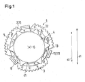
- Fig. 1 shows in a schematic representation in section an embodiment of an inventive synchronizer ring, which is hereinafter referred to collectively with the reference numeral 1.
- like reference numerals in the various figures indicate technically equivalent features or relate to features with technically equivalent function.
- the synchronizer ring 1 of Fig. 1 includes a conical annular body 3 with an inner friction surface 4 with carbon friction lining 41 and an outer mounting surface 5, which limit the annular body 3 in a radial circumferential direction in a conventional manner in each case.
- the outer mounting surface 5 and the inner friction surface 4 extend substantially parallel to each other at a predeterminable friction angle ⁇ , the in Fig. 1 can not be seen, conical about an axial synchronizer ring axis 6 of the synchronizer ring. 1
- the annular body 3 is limited in the axial direction at a largest cone diameter d1 by a substantially perpendicular to the synchronizer ring axis 6 extending gear surface 7 with gear 71, and limited to a smallest cone diameter d2 by a hub surface 8.
- an anti-rotation 11 is provided, which is integrally connected to the ring body 3 and extends from the gear surface 7 of the ring body 3 in the direction of the hub surface 8, a construction as it is already known in principle from the prior art.
- the rotation 11 is according to Fig. 1 a securing tab 111, which may be formed in the direction of the mounting surface 5, for example, in the manufacture of the synchronizer ring 1 by bending over a portion of the annular body 3 initially still radially outwardly.
- the securing tab 111 is designed and arranged with respect to the installation surface such that the securing tab 111 can be anchored in the installed state in a corresponding recess 101 of the synchronizing ring hub 10.
- a guide member 12 is provided, which is enormously important in practice Embodiment of Fig. 1 in the form of a lifting 12 of the annular body 3 is formed on the mounting surface 5, wherein the bulge 12 extends radially outwardly away from the synchronizer ring axis 6.
- the bulges 12 according to the invention center and guide the synchronizer ring 1 reliably and reliably in the cylindrical cavity 9 provided in the synchronizer ring hub 10 for receiving the mounting surface 5.
- Fig. 2 is a side view of a synchronizer ring 1 according Fig. 1 shown schematically in the installed state. The section is along the arrow A according to Fig. 3 just chosen so that the securing tab 111 is not visible.
- the synchronizer ring 1 is centered by the inventive guide elements 12, which are provided as bulges 12, with the mounting surface 5 in the cavity 9 of the synchronizer ring hub 10.
- the gear surface 7 with gear 71 is located in a conventional manner outside the synchronizer hub 10, so that the gear 71 with another, in Fig. 2 not shown gear of a switchable change-speed transmission also not shown in rotationally fixed engagement can occur.
- Fig. 3 is finally the synchronizer ring again Fig. 1 from a direction B according to Fig. 2 in a section along and at the point C, as indicated by the arrow C in Fig. 2 is specified in more detail.
- Fig. 3 is particularly easy to see how to fix the synchronizer ring 1 in the cylindrical cavity 9 of the synchronizer ring hub 10, the rotation 11, which is integrally connected to the ring body 3 and extending from the gear surface 7 of the ring body 3 in the direction of the hub surface 8, and how already mentioned a securing tab 111 is anchored in the recess 101 of the synchronizer ring hub 10.
- FIG. 4 Another special embodiment of the present invention is shown schematically in FIG. 4, wherein the anti-rotation device 11 is a securing lug 111 which is designed as a securing lug 1110 with pocket-shaped recesses, so that these are anchored in a corresponding recess of another synchronizing ring hub 10 can, wherein the recesses for anchoring the securing tabs 1110 of the other synchronizer ring hub 10 then, for example are formed in two parts with a central web, whereby in certain cases a better fixation of the synchronizer ring 1 on the synchronizer hub 10 is possible.
- the anti-rotation device 11 is a securing lug 111 which is designed as a securing lug 1110 with pocket-shaped recesses, so that these are anchored in a corresponding recess of another synchronizing ring hub 10 can, wherein the recesses for anchoring the securing tabs 1110 of the other synchronizer ring hub 10 then, for example are formed in two parts
Description
Die Erfindung betrifft einen Synchronring für eine Synchronisiereinrichtung eines schaltbaren Zahnräderwechselgetriebes sowie ein Schaltgetriebe für ein Fahrzeug gemäss dem Oberbegriff der unabhängigen Ansprüche 1 und 9.The invention relates to a synchronizer ring for a synchronizer of a shiftable change-speed gearbox and a transmission for a vehicle according to the preamble of
Synchronringe dienen in einem mechanischen schaltbaren Zahnräderwechselgetriebe, z.B. in Fahrzeuggetrieben dazu, die während eines Gangwechsels auftretenden Relativgeschwindigkeiten zwischen Gangrad und Getriebewelle aneinander anzugleichen. Die Synchronisation wird dabei durch Reibung zwischen den entsprechenden Reibpartner erzielt. Die Funktionsweise solcher Getriebe und der Ablauf des Synchronisationsvorgangs sind an sich bekannt und brauchen dem Fachmann hier nicht mehr näher erläutert zu werden.Synchronizer rings serve in a mechanical shiftable change-speed gearbox, e.g. in vehicle transmissions to match the occurring during a gear change relative speeds between gear and gear shaft to each other. The synchronization is achieved by friction between the corresponding friction partner. The mode of operation of such transmissions and the course of the synchronization process are known per se and need not be explained in more detail to the person skilled in the art.
Zum Schutz gegen vorzeitigen Verschleiss und / oder zur Verbesserung der Reibcharakteristik ist es bekannt, die Reibflächen von Synchronringen, die in der Regel aus einem Metall oder einer Metallegierung, wie beispielsweise aus Messing oder Stahl gefertigt sind, mit einer Reibschicht zu versehen. Dabei sind ganz verschiedene Typen von Reibschichten im Gebrauch, z.B. thermische Spritzschichten aus Molybdän, Carbon-Reibschichten oder Reibschichten aus anderen Materialien.To protect against premature wear and / or to improve the friction characteristic, it is known to provide the friction surfaces of synchronizer rings, which are usually made of a metal or a metal alloy, such as brass or steel, with a friction layer. There are very different types of friction layers in use, eg thermal spray coatings of molybdenum, carbon friction coatings or friction coatings of other materials.
In der
In der
Die
Beide Synchronringe sind zwar im Betriebszustand gegen eine Verdrehung gegenüber der Synchronringnabe durch die Lappen oder Anschläge im Prinzip gut gesichert, jedoch fehlt es beiden an einer zuverlässigen Führung in radialer Richtung im zylindrischen Hohlraum in der Synchronringnabe.Although both synchronizer rings are well secured in the operating state against rotation relative to the Synchronringnabe by the lobes or attacks in principle, but both lack a reliable guide in the radial direction in the cylindrical cavity in the synchronizer hub.
Das heisst, gegen eine Verdrehung in Umfangsrichtung in Bezug auf die Synchronringnabe sind die aus dem Stand der Technik bekannten Synchronring zwar gesichert, jedoch neigen diese Ringe aufgrund ihrer konischen äusseren Form, die mit einer zylindrischen inneren Kontaktfläche im zylindrischen Hohlraum der Synchronringnabe zusammenwirkt, verstärkt zu unkontrollierten Bewegungen, z.B. zu kleinen radialen Auslenkungen oder Kippbewegungen, die sich z.B. in unangenehmen Vibrationen äussern können, damit die Zuverlässigkeit und Genauigkeit des Synchronisationsvorgangs negativ beeinflussen, was zu einer Erhöhung der Schaltzeiten führen kann, zu schnellerem und erhöhtem Verschleiss der Reibfläche und des gesamten Synchronrings als solchem führt, und somit zu kürzeren Reparatur- und Wartungsintervallen führt, ganz abgesehen davon, dass durch die schlechte Führung des Synchronrings im Hohlraum der Synchronringnabe und den daraus resultierenden unkontrollierten Bewegungen der Schalt- und Fahrkomfort eines Kraftfahrzeugs deutlich eingeschränkt wird. Diese Effekte werden umso bedeutender, je mehr Leistung bzw. Drehmoment durch ein entsprechendes Getriebe geschaltet werden muss.That is, against a rotation in the circumferential direction with respect to the synchronizing ring hub known from the prior art synchronizer ring are indeed secured, but these rings tend due to their conical outer shape, which cooperates with a cylindrical inner contact surface in the cylindrical cavity of the Synchronringnabe, amplified to uncontrolled movements, such as too small radial deflections or tilting movements, which can be expressed eg in unpleasant vibrations, so that the reliability and accuracy of the synchronization process adversely affect what can lead to an increase in the switching times, leads to faster and increased wear of the friction surface and the entire synchronizer ring as such, and thus leads to shorter repair and maintenance intervals, quite apart from the fact that due to the poor leadership of the synchronizer ring in the cavity of the synchronizer ring hub and Resulting uncontrolled movements of the switching and driving comfort of a motor vehicle is significantly limited. These effects become more significant, the more power or torque must be switched by a corresponding gear.
Die Aufgabe der Erfindung ist es daher, einen verbesserten Synchronring bereitzustellen, der besser in der Synchronringnabe geführt ist und bei dem im Betriebszustand keine unkontrollierten Relativbewegungen zwischen Synchronring und Synchronringnabe während und / oder ausserhalb des Synchronisationsvorgangs auftreten.The object of the invention is therefore to provide an improved synchronizer ring, which is better guided in the synchronizer ring hub and in which no uncontrolled relative movements between synchronizer ring and Synchronringnabe during and / or outside the synchronization process occur in the operating state.
Die diese Aufgaben lösenden Gegenstände der Erfindung sind durch die Merkmale der unabhängigen Ansprüche 1 und 9 gekennzeichnet.The objects of the invention solving these objects are characterized by the features of
Die abhängigen Ansprüche beziehen sich auf besonders vorteilhafte Ausführungsformen der Erfindung.The dependent claims relate to particularly advantageous embodiments of the invention.
Die Erfindung betrifft somit einen Synchronring für eine Synchronisiereinrichtung eines schaltbaren Zahnräderwechselgetriebes, umfassend einen konischen Ringkörper mit einer inneren Reibfläche und einer äusseren Einbaufläche, die den Ringkörper in einer radialen Umfangsrichtung jeweils begrenzen, und sich unter einem vorgebbaren Reibwinkel konisch um eine axiale Synchronringachse des Synchronrings erstrecken. Dabei ist der Ringkörper in axialer Richtung an einem grössten Konusdurchmesser durch eine im wesentlichen sich senkrecht zur Synchronringachse erstreckenden Zahnradfläche mit Zahnrad begrenzt, und an einem kleinsten Konusdurchmesser durch eine Nabenfläche begrenzt. Zur Fixierung des Synchronrings in einem zylindrischen Hohlraum einer Synchronringnabe ist eine Verdrehsicherung vorgesehen, die integral mit dem Ringkörper verbunden ist und sich von der Zahnradfläche des Ringkörpers in Richtung zur Nabenfläche erstreckt. Zur Führung der Einbaufläche ist an einer Innenfläche des zylindrischen Hohlraums der Synchronringnabe am Ringkörper in einem vorgebbaren Bereich zwischen der Zahnradfläche und der Nabenfläche ein Führungselement vorgesehen. Erfindungsgemäss ist der Synchronring ein aus einem tiefziehbaren Blech hergestelltes Blechumformteil.The invention thus relates to a synchronizer ring for a synchronizer of a switchable change-speed gearbox, comprising a conical annular body with an inner friction surface and an outer mounting surface, which define the annular body in a radial circumferential direction in each case, and extend at a predeterminable friction angle conically around an axial synchronizer ring axis of the synchronizer ring. In this case, the annular body is limited in the axial direction at a largest cone diameter by a substantially perpendicular to the synchronizer ring axis extending gear surface with gear, and limited to a smallest cone diameter by a hub surface. In order to fix the synchronizing ring in a cylindrical cavity of a synchronizing ring hub, an anti-twist device is provided, which is integrally connected to the annular body and extends from the toothed wheel surface of the annular body in the direction of the hub surface. To guide the mounting surface, a guide element is provided on an inner surface of the cylindrical cavity of the synchronizing ring hub on the annular body in a predeterminable area between the gear surface and the hub surface. According to the invention, the synchronizer ring is a sheet metal formed part produced from a thermoformable sheet metal.
Wesentlich für die Erfindung ist es, dass zur Abstützung bzw. Zentrierung und Führung der Einbaufläche an einer Innenfläche des zylindrischen Hohlraums der Synchronringnabe am Ringkörper in einem vorgebbaren Bereich zwischen der Zahnradfläche und der Nabenfläche ein Führungselement vorgesehen ist, das bevorzugt in Form von mehreren Ausbeulungen, die über die Einbaufläche in Umfangsrichtung verteilt sind, bereitgestellt wird.It is essential for the invention that a guide element is provided for supporting or centering and guiding the mounting surface on an inner surface of the cylindrical cavity of the synchronizing ring hub on the annular body in a predeterminable area between the gear surface and the hub surface, preferably in the form of several bulges, which are distributed over the mounting surface in the circumferential direction, is provided.
Dadurch, dass zusätzlich zu den Führungselementen auch Verdrehsicherungen, bevorzugt in Form von Sicherungslaschen vorgesehen sind, ist ein erfindungsgemässer Synchronring gleichzeitig gegen eine Verdrehung gegenüber der Synchronringnabe durch die Verdrehsicherungen hervorragend gesichert, und ist gleichzeitig zuverlässig, insbesondere in Bezug auf die radiale Richtung im zylindrischen Hohlraum in der Synchronringnabe geführt und zentriert.Characterized in that in addition to the guide elements and anti-rotation, are preferably provided in the form of locking tabs, a synchronizer ring according to the invention is at the same time outstandingly secured against rotation relative to the Synchronringnabe by Verdrehsicherungen, and is also reliable, especially with respect to the radial direction in the cylindrical cavity guided and centered in the synchronizer ring hub.
Das heisst, ein erfindungsgemässer Synchronring neigt aufgrund seiner konischen äusseren Form, die mit einen zylindrischen inneren Kontaktfläche im zylindrischen Hohlraum der Synchronringnabe zusammenwirkt, nicht mehr, wie die aus dem Stand der Technik bekannten konischen Synchronringe, zu unkontrollierten Bewegungen, z.B. zu kleinen radialen Auslenkungen oder Kippbewegungen, die sich z.B. in unangenehmen Vibrationen äussern können. Dadurch wird die Zuverlässigkeit und Genauigkeit des Synchronisationsvorgangs durch Verwendung eines erfindungsgemässen Synchronrings deutlich positiv beeinflusst, was zu einer Erniedrigung der Schaltzeiten betragen kann, den Verschleiss an der Reibfläche und des gesamten Synchronrings als solchem reduziert und somit zu längeren Reparatur- und Wartungsintervallen beiträgt, ganz abgesehen davon, dass durch die hervorragende Führung des erfindungsgemässen Synchronrings im Hohlraum der Synchronringnabe der Schalt- und Fahrkomfort eines Kraftfahrzeugs deutlich erhöht wird. Diese positiven Effekte wirken sich umso stärker aus, je mehr Leistung bzw. Drehmoment durch ein entsprechendes Getriebe geschaltet werden muss.That is, a synchronizer ring according to the present invention, due to its conical outer shape, which cooperates with a cylindrical inner contact surface in the cylindrical cavity of the synchronizer ring hub, no longer tends, like the conical synchronizer rings known from the prior art, to uncontrolled movements, e.g. to small radial deflections or tilting movements, e.g. can express in unpleasant vibrations. Thus, the reliability and accuracy of the synchronization process by using a synchronizer ring according to the invention is significantly positively influenced, which can be a reduction in the switching times, reduces the wear on the friction surface and the entire synchronizer ring as such and thus contributes to longer repair and maintenance intervals, quite apart of the fact that the switching and driving comfort of a motor vehicle is significantly increased by the excellent guidance of the synchronizing ring according to the invention in the cavity of the synchronizing ring hub. These positive effects have the stronger effect, the more power or torque must be switched by a corresponding gear.
In einem speziellen Ausführungsbeispiel ist die Zahnradfläche durch eine Ausnehmung, insbesondere durch eine, oder zwei, oder drei, oder mehr als drei Ausnehmungen unterbrochen, und / oder die Verdrehsicherung ist in der Ausnehmung mit dem Ringkörper verbunden.In a specific embodiment, the gear surface is interrupted by a recess, in particular by one, or two, or three, or more than three recesses, and / or the rotation is connected in the recess with the annular body.
Dabei sind bevorzugt, aber nicht notwendig, ebenso viele Verdrehsicherungen wie Ausnehmungen in der Zahnradfläche vorgesehen. In einem für die Praxis besonders wichtigen Ausführungsbeispiel sind genau drei Verdrehsicherungen vorgesehen, die bei minimalem konstruktivem Aufwand ein Maximum an Verdrehsicherung garantieren.Here are preferred, but not necessary, as many anti-rotation as recesses provided in the gear surface. In a particularly important for practice embodiment exactly three anti-rotation are provided which guarantee a maximum of rotation with minimal design effort.
Insbesondere kann die Verdrehsicherung als Sicherungslasche ausgebildet sein, die sich auf der der Synchronringachse abgewandten Seite des Ringkörpers im wesentlichen gleichgerichtet zur Einbaufläche erstreckt.In particular, the rotation can be formed as a securing tab, which extends on the side facing away from the synchronizer ring axis of the ring body substantially rectified to the mounting surface.
In einem ganz speziellen Ausführungsbeispiel kann die Sicherungslasche eine Sicherungslasche mit einer taschenförmigen Ausnehmung sein, wodurch im Einzelfall eine verbesserte Verankerung des Synchronrings in der Synchronringnabe erreichbar ist.In a very specific embodiment, the securing tab may be a securing tab with a pocket-shaped recess, whereby in an individual case an improved anchoring of the synchronizing ring in the synchronizing ring hub can be achieved.
Die Zahl der Führungselemente, die an einem erfindungsgemässen Synchronring vorgesehen sein können, liegt bevorzugt zwischen zwei und neun Führungselementen, im Speziellen drei Führungselemente, wobei besonders bevorzugt sechs Führungselemente vorgesehen sind, und /oder jeweils zwei Führungselemente in Umfangsrichtung in im wesentlichen gleichem Abstand und / oder jeweils zwei Führungselemente zwischen zwei Verdrehsicherungen angeordnet sind, wodurch bei minimalem konstruktivem Aufwand ein Höchstmass an radialer Führung gewährleistbar ist.The number of guide elements, which may be provided on a synchronizer ring according to the invention, is preferably between two and nine guide elements, in particular three guide elements, more preferably six guide elements are provided, and / or two guide elements in the circumferential direction at substantially the same distance and / or in each case two guide elements are arranged between two anti-rotation, whereby with minimal design effort, a maximum amount of radial guidance is guaranteed.
Erfindungsgemäß ist das Führungselement in Form einer Ausbeulung des Ringkörpers an der Einbaufläche ausgebildet, welche Ausbeulung sich von der Synchronringachse radial weg nach aussen erstreckt.According to the invention, the guide element is designed in the form of a bulge of the annular body on the mounting surface, which bulge extends radially away from the synchronizer ring axis.
Bevorzugt ist auf oder an der Reibfläche ein Verschleiss minderndes und /oder ein reibungsoptimiertes Reibungsmittel, insbesondere eine Reibbeschichtung, im speziellen eine Molybdänbeschichtung und / oder ein Reibbelag, insbesondere ein Carbon-Reibbelag und / oder ein anderes Reibungsmittel vorgesehen.Preferably, a wear-reducing and / or friction-optimized friction means, in particular a friction coating, in particular a molybdenum coating and / or a friction lining, in particular a carbon friction lining and / or another friction means is provided on or on the friction surface.
Konstruktiv ist der Synchronring ein aus einem tiefziehbaren Blech hergestelltes Blechumformteil und / oder aus einem Stahl, vorzugsweise aus C55, C80 oder C80M Stahl, insbesondere aus C35 oder C45 Stahl gefertigt.Constructively, the synchronizer ring is made of a thermoformable sheet metal formed part and / or made of a steel, preferably made of C55, C80 or C80M steel, in particular C35 or C45 steel.
Die Erfindung bezieht sich weiter auf ein Schaltgetriebe für ein Fahrzeug, insbesondere für einen Personenkraftwagen, einen Transporter oder einen Lastkraftwagen mit einem Synchronring nach einem der vorangehenden Ansprüche.The invention further relates to a manual transmission for a vehicle, in particular for a passenger car, a van or a truck with a synchronizer ring according to one of the preceding claims.
Im Folgenden wird die Erfindung an Hand der schematischen Zeichnung näher erläutert. Es zeigen :
- Fig. 1
- ein Ausführungsbeispiel eines erfindungsgemässen Synchronrings im Schnitt;
- Fig. 2
- eine Seitenansicht eines Synchronrings gemäss
Fig. 1 im Einbauzustand; - Fig. 3
- eine andere Ansicht gemäss
Fig. 2 ; - Fig. 4
- eine Sicherungslasche mit taschenförmiger Ausnehmung.
- Fig. 1
- an embodiment of an inventive synchronizer ring in section;
- Fig. 2
- a side view of a synchronizer ring according
Fig. 1 in the installed state; - Fig. 3
- a different view according to
Fig. 2 ; - Fig. 4
- a locking tab with pocket-shaped recess.
Der Synchronring 1 der
Dabei ist der Ringkörper 3 in axialer Richtung an einem grössten Konusdurchmesser d1 durch eine im wesentlichen sich senkrecht zur Synchronringachse 6 erstreckenden Zahnradfläche 7 mit Zahnrad 71 begrenzt, und an einem kleinsten Konusdurchmesser d2 durch eine Nabenfläche 8 begrenzt. Zur Fixierung des Synchronrings 1 in einem zylindrischen Hohlraum 9 einer Synchronringnabe 10, die in
Das heisst, die Verdrehsicherung 11, die als Sicherungslasche 111 ausgebildet ist, erstreckt sich auf der der Synchronringachse 6 abgewandten Seite des Ringkörpers 3 im wesentlichen gleichgerichtet zur Einbaufläche 5.That is, the rotation 11, which is designed as a
Wie später anhand der nachfolgenden Figuren noch genauer erläutert werden wird, ist die Sicherungslasche 111 derart ausgebildet und in Bezug auf die Einbaufläche angeordnet, dass die Sicherungslasche 111 im Einbauzustand in einer entsprechenden Ausnehmung 101 der Synchronringnabe 10 verankerbar ist.As will be explained in more detail later with reference to the following figures, the securing
Erfindungsgemäss ist zur Führung der Einbaufläche 5 an einer Innenfläche 91 des zylindrischen Hohlraums 9 der Synchronringnabe 10, die wie gesagt in
Im Einbauzustand des Synchronrings 1 zentrieren und führen die erfindungsgemässen Ausbeulungen 12 dann den Synchronring 1 sicher und zuverlässig in dem in der Synchronringnabe 10 zur Aufnahme der Einbaufläche 5 vorgesehenen zylindrischen Hohlraum 9.In the installed state of the
In
Der konische Ringkörper 3 mit seiner inneren Reibfläche 4, die im vorliegenden Beispiel einen Carbon-Reibbelag 41 aufweist, und der äusseren Einbaufläche 5, erstrecken sich unter dem Reibwinkel α konisch und im wesentlichen parallel zueinander um die axiale Synchronrigachse 6 des Synchronrings 1.The conical
Der Synchronring 1 ist durch die erfindungsgemässen Führungselemente 12, die als Ausbeulungen 12 vorgesehen sind, mit der Einbaufläche 5 im Hohlraum 9 der Synchronringnabe 10 zentriert gelagert.The
Die Zahnradfläche 7 mit Zahnrad 71 befindet sich in an sich bekannter Weise ausserhalb der Synchronringnabe 10, so dass das Zahnrad 71 mit einem weiteren, in
In
In
In Fg. 4 ist schliesslich ein anderes spezielles Ausführungsbeispiel der vorliegenden Erfindung in schematischer Weise dargestellt, wobei die Verdrehsicherung 11 eine Sicherungslasche 111 ist, die als Sicherungslasche 1110 mit taschenförmigen Ausnehmungen ausgestaltet ist, so dass diese in einer entsprechenden Ausnehmung einer anderen Synchronringnabe 10 verankert werden können, wobei die Ausnehmungen zur Verankerung der Sicherungslaschen 1110 der anderen Synchronringnabe 10 dann entsprechend z.B. zweiteilig mit einem mittleren Steg ausgebildet sind, wodurch in bestimmten Fällen eine bessere Fixierung des Synchronrings 1 an der Synchronringnabe 10 möglich ist.Finally, another special embodiment of the present invention is shown schematically in FIG. 4, wherein the anti-rotation device 11 is a securing
Es versteht sich, dass alle in dieser Anmeldung explizit diskutierten Ausführungsbeispiele nur exemplarisch für die Erfindung zu verstehen sind.It is understood that all embodiments explicitly discussed in this application are to be understood as exemplary of the invention.
Claims (9)
- A synchroniser ring for a synchronising device (2) of a switchable gear changing transmission including a conical ring body (3) having an inner friction surface (4) and an outer installation surface (5) which each bound the ring body (3) in a radial peripheral direction and extend conically at a presettable friction angle (α) about an axial synchroniser ring axis (6) of the synchroniser ring, wherein the ring body (3) is bounded in the axial direction at a largest cone diameter (d1) by a gear surface (7) with gear (71) and extending substantially perpendicular to the synchroniser ring axis (6) and is bounded at a smallest conical diameter (d2) by a hub surface (8) and, to fix the synchroniser ring in a cylindrical hollow space (9) of a synchroniser ring hub (10), a security against rotation (11) is provided which is integrally connected to the ring body (3) and extends from the gear surface (7) of the ring body (3) in the direction towards the hub surface (8), wherein a guide element (12) is provided for the guidance of the installation surface (5) at an inner surface (91) of the cylindrical hollow space (9) of the synchroniser ring hub (10) at the ring body (3) in a presettable region between the gear surface (7) and the hub surface (8), characterised in that the guide element (12) is configured in the form of an indentation (12) of the ring body (3) at the installation surface (5), which indentation (12) extends radially outwardly away from the synchroniser ring axis (6) and the synchroniser ring is a shaped sheet metal part manufactured from a deep-drawable sheet metal
- A synchroniser ring in accordance with claim 1, wherein the gear surface (7) is interrupted by a cut-out (13), in particular by one, or two, or three, or more than three cut-outs (13); and/or the security against rotation (11) is connected to the ring body (3) in the cut-out (13).
- A synchroniser ring in accordance with one of the claims 1 or 2, wherein just as many securities against rotation (11) are provided as cut-outs (13) in the gear surface (7), in particular precisely three securities against rotation (11).
- A synchroniser ring in accordance with any one of the preceding claims, wherein the security against rotation (11) is configured as a securing lug (111) which extends on the side of the ring body (3) remote from the synchroniser ring axis (6) substantially directed the same towards the installation surface (5).
- A synchroniser ring in accordance with any one of the preceding claims, wherein the securing lug (111) is a securing lug (1110) having a pocket-like cut-out.
- A synchroniser ring in accordance with any one of the preceding claims, wherein between two and nine guide elements (12), specifically three guide elements (12), preferably six guide elements (12) are provided, with particularly preferably in each case two guide element (12) being arranged at substantially the same interval in the peripheral direction and/or in each case two guide members (12) being arranged between two securities against rotation (11, 111).
- A synchroniser ring in accordance with any one of the preceding claims, wherein a wear reducing and/or a friction optimised friction means (41), in particular a friction coating (41), specifically a molybdenum coating (41) and/or a friction layer (41), in particular a carbon friction layer (41) and/or another friction means (41) is provided on the friction surface (4).
- A synchroniser ring in accordance with any one of the preceding claims, wherein the synchroniser ring is produced from a steel, preferably from C55, C80 or C80M steel, in particular from C35 or C45 steel.
- A shift transmission for a vehicle, in particular for a passenger car, a transporter or a truck, having a synchroniser ring (1) in accordance with any one of the preceding claims.
Priority Applications (1)
| Application Number | Priority Date | Filing Date | Title |
|---|---|---|---|
| EP07112152A EP1900955B1 (en) | 2006-09-15 | 2007-07-10 | Synchroniser ring |
Applications Claiming Priority (2)
| Application Number | Priority Date | Filing Date | Title |
|---|---|---|---|
| EP06120716 | 2006-09-15 | ||
| EP07112152A EP1900955B1 (en) | 2006-09-15 | 2007-07-10 | Synchroniser ring |
Publications (2)
| Publication Number | Publication Date |
|---|---|
| EP1900955A1 EP1900955A1 (en) | 2008-03-19 |
| EP1900955B1 true EP1900955B1 (en) | 2010-11-10 |
Family
ID=39079466
Family Applications (1)
| Application Number | Title | Priority Date | Filing Date |
|---|---|---|---|
| EP07112152A Active EP1900955B1 (en) | 2006-09-15 | 2007-07-10 | Synchroniser ring |
Country Status (1)
| Country | Link |
|---|---|
| EP (1) | EP1900955B1 (en) |
Families Citing this family (2)
| Publication number | Priority date | Publication date | Assignee | Title |
|---|---|---|---|---|
| KR101558402B1 (en) | 2008-06-18 | 2015-10-07 | 오엘리콘 프릭션 시스템즈 (져머니) 게엠베하 | Synchronizing ring and gear changing transmission for a vehicle |
| FR2938031A1 (en) * | 2008-11-04 | 2010-05-07 | Renault Sas | ABSORPTION OF TORQUE OSCILLATIONS FOR DEVICE FOR COUPLING A GEARBOX SHAFT WITH AN IDLE PINION MOUNTED ON THIS TREE |
Citations (1)
| Publication number | Priority date | Publication date | Assignee | Title |
|---|---|---|---|---|
| EP0717212A1 (en) * | 1994-12-13 | 1996-06-19 | HOERBIGER & Co. | Synchronising device for gearbox |
Family Cites Families (4)
| Publication number | Priority date | Publication date | Assignee | Title |
|---|---|---|---|---|
| DE3519811C2 (en) * | 1985-06-03 | 1994-05-11 | Borg Warner Automotive Gmbh | Carrier for a synchronization ring |
| SE9404489L (en) * | 1994-12-21 | 1996-01-15 | Saab Automobile | Device for preventing junk in a synchronized gearbox |
| DE19719618B4 (en) * | 1997-05-09 | 2005-08-04 | Ina-Schaeffler Kg | Synchronizer ring, which is composed of several individual parts |
| DE19922325C1 (en) * | 1999-05-14 | 2000-07-13 | Daimler Chrysler Ag | Switch sleeve carrier for the switch sleeve at a gear shaft in a manual synchromesh gearbox has a passage in the base to take an insert in a durable fit with the spring support to reduce costs |
-
2007
- 2007-07-10 EP EP07112152A patent/EP1900955B1/en active Active
Patent Citations (1)
| Publication number | Priority date | Publication date | Assignee | Title |
|---|---|---|---|---|
| EP0717212A1 (en) * | 1994-12-13 | 1996-06-19 | HOERBIGER & Co. | Synchronising device for gearbox |
Also Published As
| Publication number | Publication date |
|---|---|
| EP1900955A1 (en) | 2008-03-19 |
Similar Documents
| Publication | Publication Date | Title |
|---|---|---|
| EP2136098B1 (en) | Synchronising ring and a cog-wheel gearbox for a motor vehicle | |
| DE102008023031B4 (en) | Sheet synchronizer ring | |
| EP2894363B1 (en) | Friction ring, synchronisation ring, synchronisation unit and a variable speed gearbox for a motor vehicle | |
| EP2677187B1 (en) | Friction ring, synchronisation unit and a wheel gear box for a motor vehicle | |
| EP2677188B1 (en) | Synchronizer ring | |
| EP2739874B1 (en) | Slave cylinder | |
| WO2000031429A1 (en) | Assembly and realisation of synchronisation rings in the form of sheet metal parts shaped without cutting | |
| DE102006018284A1 (en) | Synchronization device e.g. multi-cone synchronization device, for use in vehicle gear, has press part lying in area of external teeth of synchronous body, and synchronous ring with switching tooth designed as sheet molded part | |
| DE102016217196A1 (en) | Pressure piece of a vehicle transmission and synchronization unit | |
| DE102011015836A1 (en) | Sheet-synchronizing ring for synchronization unit of manual transmission, has projections designed at band at distance from tabs in direction, where serration of band continuously extends over region radially outside projections | |
| DE102016216496A1 (en) | screw | |
| DE102008004924A1 (en) | Collar for frontal teeth for a drivable hub | |
| EP1175569B1 (en) | Built-up synchroniser body with a stop element | |
| EP1900955B1 (en) | Synchroniser ring | |
| WO2008025585A1 (en) | Synchronizing device comprising steel and brass elements combined with a friction coating | |
| EP1936223B1 (en) | Synchronizer ring | |
| DE102012220652A1 (en) | camshaft | |
| DE112012001466B4 (en) | Actuating device for actuating clutch devices | |
| EP1711728B1 (en) | Selector fork | |
| DE102015001442B4 (en) | Brake assembly with a brake pad carrier and a driver | |
| EP3153732B1 (en) | Friction ring for a synchronizing unit | |
| DE102019120225A1 (en) | Valve and device for regulating pressures of a fluid with the valve and device for securing the valve in the transmission component | |
| EP1887240A1 (en) | Synchro ring | |
| DE102012006058A1 (en) | Adjusting device for motor vehicle component, has brake element, which is disposed between brake ring and rotary element, where clamping ring is brought into frictional contact with brake ring for additional locking of rotary element | |
| EP3551898B1 (en) | Shaft assembly having a fluid-damming ring |
Legal Events
| Date | Code | Title | Description |
|---|---|---|---|
| PUAI | Public reference made under article 153(3) epc to a published international application that has entered the european phase |
Free format text: ORIGINAL CODE: 0009012 |
|
| AK | Designated contracting states |
Kind code of ref document: A1 Designated state(s): AT BE BG CH CY CZ DE DK EE ES FI FR GB GR HU IE IS IT LI LT LU LV MC MT NL PL PT RO SE SI SK TR |
|
| AX | Request for extension of the european patent |
Extension state: AL BA HR MK YU |
|
| 17P | Request for examination filed |
Effective date: 20080401 |
|
| 17Q | First examination report despatched |
Effective date: 20080508 |
|
| AKX | Designation fees paid |
Designated state(s): DE FR GB IT |
|
| GRAP | Despatch of communication of intention to grant a patent |
Free format text: ORIGINAL CODE: EPIDOSNIGR1 |
|
| GRAC | Information related to communication of intention to grant a patent modified |
Free format text: ORIGINAL CODE: EPIDOSCIGR1 |
|
| RAP1 | Party data changed (applicant data changed or rights of an application transferred) |
Owner name: SULZER FRICTION SYSTEMS (GERMANY) GMBH |
|
| GRAS | Grant fee paid |
Free format text: ORIGINAL CODE: EPIDOSNIGR3 |
|
| GRAA | (expected) grant |
Free format text: ORIGINAL CODE: 0009210 |
|
| AK | Designated contracting states |
Kind code of ref document: B1 Designated state(s): DE FR GB IT |
|
| REG | Reference to a national code |
Ref country code: GB Ref legal event code: FG4D Free format text: NOT ENGLISH |
|
| REF | Corresponds to: |
Ref document number: 502007005600 Country of ref document: DE Date of ref document: 20101223 Kind code of ref document: P |
|
| PLBE | No opposition filed within time limit |
Free format text: ORIGINAL CODE: 0009261 |
|
| STAA | Information on the status of an ep patent application or granted ep patent |
Free format text: STATUS: NO OPPOSITION FILED WITHIN TIME LIMIT |
|
| 26N | No opposition filed |
Effective date: 20110811 |
|
| REG | Reference to a national code |
Ref country code: DE Ref legal event code: R097 Ref document number: 502007005600 Country of ref document: DE Effective date: 20110811 |
|
| REG | Reference to a national code |
Ref country code: FR Ref legal event code: PLFP Year of fee payment: 10 |
|
| REG | Reference to a national code |
Ref country code: FR Ref legal event code: PLFP Year of fee payment: 11 |
|
| REG | Reference to a national code |
Ref country code: FR Ref legal event code: PLFP Year of fee payment: 12 |
|
| PGFP | Annual fee paid to national office [announced via postgrant information from national office to epo] |
Ref country code: IT Payment date: 20230721 Year of fee payment: 17 Ref country code: GB Payment date: 20230725 Year of fee payment: 17 |
|
| PGFP | Annual fee paid to national office [announced via postgrant information from national office to epo] |
Ref country code: FR Payment date: 20230725 Year of fee payment: 17 Ref country code: DE Payment date: 20230726 Year of fee payment: 17 |