EP1900904A2 - Multi-peripheral serpentine microcircuits for high aspect ratio blades - Google Patents
Multi-peripheral serpentine microcircuits for high aspect ratio blades Download PDFInfo
- Publication number
- EP1900904A2 EP1900904A2 EP07253511A EP07253511A EP1900904A2 EP 1900904 A2 EP1900904 A2 EP 1900904A2 EP 07253511 A EP07253511 A EP 07253511A EP 07253511 A EP07253511 A EP 07253511A EP 1900904 A2 EP1900904 A2 EP 1900904A2
- Authority
- EP
- European Patent Office
- Prior art keywords
- cooling
- leg
- circuit
- serpentine
- pressure side
- Prior art date
- Legal status (The legal status is an assumption and is not a legal conclusion. Google has not performed a legal analysis and makes no representation as to the accuracy of the status listed.)
- Granted
Links
- WYTGDNHDOZPMIW-RCBQFDQVSA-N alstonine Natural products C1=CC2=C3C=CC=CC3=NC2=C2N1C[C@H]1[C@H](C)OC=C(C(=O)OC)[C@H]1C2 WYTGDNHDOZPMIW-RCBQFDQVSA-N 0.000 title claims description 11
- 238000001816 cooling Methods 0.000 claims abstract description 90
- 239000012809 cooling fluid Substances 0.000 claims description 13
- 239000002184 metal Substances 0.000 description 6
- 239000002826 coolant Substances 0.000 description 5
- 238000005516 engineering process Methods 0.000 description 5
- VYPSYNLAJGMNEJ-UHFFFAOYSA-N Silicium dioxide Chemical group O=[Si]=O VYPSYNLAJGMNEJ-UHFFFAOYSA-N 0.000 description 4
- 230000002093 peripheral effect Effects 0.000 description 4
- 239000003870 refractory metal Substances 0.000 description 3
- 238000000034 method Methods 0.000 description 2
- 238000012986 modification Methods 0.000 description 2
- 230000004048 modification Effects 0.000 description 2
- 230000003416 augmentation Effects 0.000 description 1
- 239000000446 fuel Substances 0.000 description 1
- 239000000463 material Substances 0.000 description 1
- 230000008092 positive effect Effects 0.000 description 1
- 238000004781 supercooling Methods 0.000 description 1
Images

Classifications
-
- F—MECHANICAL ENGINEERING; LIGHTING; HEATING; WEAPONS; BLASTING
- F01—MACHINES OR ENGINES IN GENERAL; ENGINE PLANTS IN GENERAL; STEAM ENGINES
- F01D—NON-POSITIVE DISPLACEMENT MACHINES OR ENGINES, e.g. STEAM TURBINES
- F01D5/00—Blades; Blade-carrying members; Heating, heat-insulating, cooling or antivibration means on the blades or the members
- F01D5/12—Blades
- F01D5/14—Form or construction
- F01D5/18—Hollow blades, i.e. blades with cooling or heating channels or cavities; Heating, heat-insulating or cooling means on blades
- F01D5/187—Convection cooling
-
- F—MECHANICAL ENGINEERING; LIGHTING; HEATING; WEAPONS; BLASTING
- F05—INDEXING SCHEMES RELATING TO ENGINES OR PUMPS IN VARIOUS SUBCLASSES OF CLASSES F01-F04
- F05D—INDEXING SCHEME FOR ASPECTS RELATING TO NON-POSITIVE-DISPLACEMENT MACHINES OR ENGINES, GAS-TURBINES OR JET-PROPULSION PLANTS
- F05D2250/00—Geometry
- F05D2250/10—Two-dimensional
- F05D2250/18—Two-dimensional patterned
- F05D2250/185—Two-dimensional patterned serpentine-like
Definitions
- the present invention relates to microcircuit cooling for the pressure side of a high aspect ratio turbine engine component, such as a turbine blade.
- the overall cooling effectiveness is a measure used to determine the cooling characteristics of a particular design.
- the ideal non-achievable goal is unity, which implies that the metal temperature is the same as the coolant temperature inside an airfoil.
- the opposite can also occur when the cooling effectiveness is zero implying that the metal temperature is the same as the gas temperature. In that case, the blade material will certainly melt and burn away.
- existing cooling technology allows the cooling effectiveness to be between 0.5 and 0.6. More advanced technology such as supercooling should be between 0.6 and 0.7. Microcircuit cooling as the most advanced cooling technology in existence today can be made to produce cooling effectiveness higher than 0.7.
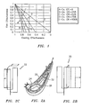
- Fig. 1 shows a durability map of cooling effectiveness (x-axis) vs. the film effectiveness (y-axis) for different lines of convective efficiency. Placed in the map is a point 10 related to a new advanced serpentine microcircuit shown in FIGS. 2A - 2C.
- This serpentine microcircuit includes a pressure side serpentine circuit 20 and a suction side serpentine circuit 22 embedded in the airfoil walls 24 and 26.
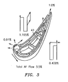
- FIG. 3 illustrates the cooling flow distribution for a turbine blade with the serpentine microcircuits of FIGS. 2a - 2c embedded in the airfoils walls.
- FIGS. 2a - 2c The design shown in FIGS. 2a - 2c leads to significant cooling flow reduction. This in turn has positive effects on cycle thermodynamic efficiency, turbine efficiency, rotor inlet temperature impacts, and specific fuel consumption.
- FIG. 4 shows that at the end of the third leg, the back flow margin, as a measure of internal to external pressure ratio, is low. As a consequence of this back flow issue, the metal temperature increase beyond that required metal temperature close to the third leg of the pressure side circuit. A remedy is needed to eliminate this problem on the aft pressure side of the airfoil.
- the present invention relates to microcircuit cooling for the pressure side of a high aspect ratio turbine engine component.
- the term "aspect ratio” may be defined as the ratio of airfoil span (height) to axial chord.
- a cooling arrangement for a pressure side of an airfoil portion of a turbine engine component.
- the cooling arrangement broadly comprises a pair of cooling circuits embedded within a wall forming the pressure side, and the pair of cooling circuits comprises a first serpentine cooling circuit and a second circuit offset from the first serpentine cooling circuit.
- a turbine engine component broadly comprising an airfoil portion having a pressure side and a suction side and a pair of cooling circuits embedded within a wall forming the pressure side.
- the pair of cooling circuits comprises a first serpentine cooling circuit and a second circuit offset from the first serpentine cooling circuit.
- FIG. 5 there is shown a schematic representation of pressure side cooling scheme for a turbine engine component 100, such as a turbine blade, having an airfoil portion 102.
- the pressure side of the airfoil portion 102 is provided with two peripheral serpentine circuits 104 and 106 offset radially from each other to minimize the heat pick-up in each circuit.
- Film cooling is provided separately by shaped holes from the main core cavities.
- the circuits 104 and 106 are embedded within the pressure side wall.
- the first circuit 104 has an inlet 108 for receiving a flow of cooling fluid from a source (not shown).
- the cooling fluid flows from the inlet 108 into a first leg 110 and then into a second leg 112. From the second leg, the cooling fluid flows into a third or outlet leg 114 through one or more tip holes 150.
- the first two legs 110 and 112 of the cooling circuit are only present in a lower span of the airfoil portion 102, i.e, below the mid-span line 120 for the airfoil portion 102.
- the circuit 106 is formed in the upper span of the airfoil portion 102, i.e. above the mid-span line 120.
- the circuit 106 has a first leg 122 which has an inlet which communicates with an internal supply cavity (not shown). Cooling fluid from the first leg 122 flows into a second leg 124 and then into the outlet leg 114. Thus, the upper part of the pressure side is convectively cooled.
- the cooling scheme as shown in this embodiment also includes a plurality of film cooling holes 115.
- the film cooling holes may be used to form a film of cooling fluid over external surfaces of the pressure side including a trailing edge portion.
- the film cooling holes 115 may be supplied with cooling fluid via one or more main core cavities such as one or more of cavities 41 shown in FIG. 3.
- the cooling circuits 104 and 106 may be formed using any suitable technique known in the art.
- the circuits may be formed using a combination of refractory metal core technology and silica core technology.
- refractory metal cores may be used to from the lower span peripheral core 130 and the upper span peripheral core 132, while silica cores may be used to form the trailing edge structure 134 and the airfoil main body 136.
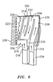
- FIG. 6 there is shown another cooling scheme for the pressure side of an airfoil portion of a turbine engine component.
- the pressure side is provided with a first cooling circuit 204 and a second cooling circuit 206.
- the first cooling circuit 204 is a serpentine cooling circuit having an inlet leg 208 which communicates with an inlet 210 which in turn communicates with a source of cooling fluid (not shown).
- the inlet leg 208 extends along the lower and upper span of the airfoil portion and communicates with a second leg 212 which in turn communicates with an third or outlet leg 214.
- the cooling fluid exits the outlet leg 214 through one or more tip holes 250.
- the cooling circuit 206 has an inlet leg 216 which communicates with a trailing edge inlet 218 which is separate from the inlet 210.
- the inlet leg 216 provides cooling fluid to a radially extending outlet leg 220 which extends over the lower and upper spans of the airfoil portion.
- a plurality of film slots 222 may be provided so that cooling fluid from the outlet leg 220 flows over the pressure side of the airfoil portion 102.
- the cooling circuits 204 and 206 may be formed using any suitable technique known in the art.
- the cooling circuits 204 and 206 may be formed using refractory metal cores for the lower span 230 and the upper span 232.
- Silica cores may be used to form the main body core 234 and the trailing edge silica core 236.
- the suction side of the airfoil portion 102 may be provided with an embedded serpentine cooling circuit such as that shown in FIG. 2C.
Landscapes
- Engineering & Computer Science (AREA)
- Mechanical Engineering (AREA)
- General Engineering & Computer Science (AREA)
- Turbine Rotor Nozzle Sealing (AREA)
Abstract
Description
- The present invention relates to microcircuit cooling for the pressure side of a high aspect ratio turbine engine component, such as a turbine blade.
- The overall cooling effectiveness is a measure used to determine the cooling characteristics of a particular design. The ideal non-achievable goal is unity, which implies that the metal temperature is the same as the coolant temperature inside an airfoil. The opposite can also occur when the cooling effectiveness is zero implying that the metal temperature is the same as the gas temperature. In that case, the blade material will certainly melt and burn away. In general, existing cooling technology allows the cooling effectiveness to be between 0.5 and 0.6. More advanced technology such as supercooling should be between 0.6 and 0.7. Microcircuit cooling as the most advanced cooling technology in existence today can be made to produce cooling effectiveness higher than 0.7.
- Fig. 1 shows a durability map of cooling effectiveness (x-axis) vs. the film effectiveness (y-axis) for different lines of convective efficiency. Placed in the map is a
point 10 related to a new advanced serpentine microcircuit shown in FIGS. 2A - 2C. This serpentine microcircuit includes a pressureside serpentine circuit 20 and a suctionside serpentine circuit 22 embedded in theairfoil walls - The Table I below provides the dimensionless parameters used to plot the design point in the durability map.
TABLE I Operational Parameters for serpentine microcircuit beta 2.898 Tg 2581 [F] Tc 1365 [F] Tm 2050 [F] Tm_bulk 1709 [F] Phi_loc 0.437 Phi_bulk 0.717 Tco 1640 [F] Tci 1090 [F] eta_c_loc 0.573 eta_f 0.296 Total Cooling Flow 3.503% WAE 10.8 Legend for Table I
Beta = dimensionless heat load parameter or ratio of convective thermal load to external thermal load
Phi_loc = local cooling effectiveness
Phi_bulk = bulk cooling effectiveness
Eta_c_loc = local cooling efficiency
Eta_f = film effectiveness
Tg = gas temperature
Tc = coolant temperature
Tm = metal temperature
Tm_bulk = bulk metal temperature
Tco = exit coolant temperature
Tci = inlet coolant temperature
WAE = compressor engine flow, pps - It should be noted that the overall cooling effectiveness from the table is 0.717 for a film effectiveness of 0.296 and a convective efficiency (or ability to pick-up heat) of 0.573 (57%). It should also be noted that the corresponding cooling flow for a turbine blade having this cooling microcircuit is 3.5% engine flow. FIG. 3 illustrates the cooling flow distribution for a turbine blade with the serpentine microcircuits of FIGS. 2a - 2c embedded in the airfoils walls.
- The design shown in FIGS. 2a - 2c leads to significant cooling flow reduction. This in turn has positive effects on cycle thermodynamic efficiency, turbine efficiency, rotor inlet temperature impacts, and specific fuel consumption.
- It should be noted from FIG. 3 that the flow passing through the pressure side serpentine microcircuit is 1.165% WAE in comparison with 0.428% WAE in the suction side serpentine microcircuit for this arrangement. This represents a 2.7 fold increase in cooling flow relative to the suction side microcircuit. The reason for this increase stems from the fact that the thermal load to the part is considerably higher for the airfoil pressure side. As a result, the height of the microcircuit channel should be a 1.8 fold increase over that of the suction side.
- Besides the increased flow requirement on the pressure side, the driving pressure drop potential in terms of source to sink pressures for the pressure side circuit is not as high as that for the suction side circuit. In considering the coolant pressure on the pressure side circuit, FIG. 4 shows that at the end of the third leg, the back flow margin, as a measure of internal to external pressure ratio, is low. As a consequence of this back flow issue, the metal temperature increase beyond that required metal temperature close to the third leg of the pressure side circuit. A remedy is needed to eliminate this problem on the aft pressure side of the airfoil.
- The present invention relates to microcircuit cooling for the pressure side of a high aspect ratio turbine engine component. The term "aspect ratio" may be defined as the ratio of airfoil span (height) to axial chord.
- In accordance with the present invention, there is provided a cooling arrangement for a pressure side of an airfoil portion of a turbine engine component. The cooling arrangement broadly comprises a pair of cooling circuits embedded within a wall forming the pressure side, and the pair of cooling circuits comprises a first serpentine cooling circuit and a second circuit offset from the first serpentine cooling circuit.
- Further, in accordance with the present invention, there is provided a turbine engine component broadly comprising an airfoil portion having a pressure side and a suction side and a pair of cooling circuits embedded within a wall forming the pressure side. The pair of cooling circuits comprises a first serpentine cooling circuit and a second circuit offset from the first serpentine cooling circuit.
- Other details of the multi-peripheral serpentine microcircuits for high aspect ratio blades of the present invention, as well as other advantages attendant thereto, are set forth in the following detailed description and the accompanying drawings wherein like reference numerals depict like elements.
-
- FIG. 1 is a graph showing cooling effectiveness versus film effectiveness for a turbine engine component;
- FIG. 2A shows an airfoil portion of a turbine engine component having a pressure side cooling microcircuit embedded in the pressure side wall and a suction side cooling microcircuit embedded in the suction side wall;
- FIG. 2B is a schematic representation of a pressure side cooling microcircuit used in the airfoil portion of FIG. 2A;
- FIG. 2C is a schematic representation of a suction side cooling microcircuit used in the airfoil portion of FIG. 2A;
- FIG. 3 illustrates the cooling flow distribution for a turbine engine component with serpentine microcircuits embedded in the airfoil walls;
- FIG. 4 is a graph illustrating the low back flow margin for the third leg of the pressure side circuit of FIG. 2B;
- FIG. 5 is a schematic representation of a pressure side cooling scheme in accordance with the present invention; and
- FIG. 6 is a schematic representation of an alternative pressure side cooling scheme in accordance with the present invention.
- Referring now to FIG. 5, there is shown a schematic representation of pressure side cooling scheme for a
turbine engine component 100, such as a turbine blade, having anairfoil portion 102. As can be seen from this figure, the pressure side of theairfoil portion 102 is provided with two peripheralserpentine circuits circuits - The
first circuit 104 has aninlet 108 for receiving a flow of cooling fluid from a source (not shown). The cooling fluid flows from theinlet 108 into afirst leg 110 and then into asecond leg 112. From the second leg, the cooling fluid flows into a third oroutlet leg 114 through one or more tip holes 150. As can be seen from FIG. 5, the first twolegs airfoil portion 102, i.e, below themid-span line 120 for theairfoil portion 102. - The
circuit 106 is formed in the upper span of theairfoil portion 102, i.e. above themid-span line 120. Thecircuit 106 has afirst leg 122 which has an inlet which communicates with an internal supply cavity (not shown). Cooling fluid from thefirst leg 122 flows into asecond leg 124 and then into theoutlet leg 114. Thus, the upper part of the pressure side is convectively cooled. - The cooling scheme as shown in this embodiment, also includes a plurality of film cooling holes 115. The film cooling holes may be used to form a film of cooling fluid over external surfaces of the pressure side including a trailing edge portion. The film cooling holes 115 may be supplied with cooling fluid via one or more main core cavities such as one or more of
cavities 41 shown in FIG. 3. - The cooling
circuits peripheral core 130 and the upper spanperipheral core 132, while silica cores may be used to form the trailingedge structure 134 and the airfoilmain body 136. - Referring now to FIG. 6, there is shown another cooling scheme for the pressure side of an airfoil portion of a turbine engine component. In this scheme, the pressure side is provided with a
first cooling circuit 204 and asecond cooling circuit 206. Thefirst cooling circuit 204 is a serpentine cooling circuit having aninlet leg 208 which communicates with aninlet 210 which in turn communicates with a source of cooling fluid (not shown). Theinlet leg 208 extends along the lower and upper span of the airfoil portion and communicates with asecond leg 212 which in turn communicates with an third oroutlet leg 214. The cooling fluid exits theoutlet leg 214 through one or more tip holes 250. Thecooling circuit 206 has aninlet leg 216 which communicates with a trailingedge inlet 218 which is separate from theinlet 210. Theinlet leg 216 provides cooling fluid to a radially extendingoutlet leg 220 which extends over the lower and upper spans of the airfoil portion. A plurality offilm slots 222 may be provided so that cooling fluid from theoutlet leg 220 flows over the pressure side of theairfoil portion 102. - The cooling
circuits circuits lower span 230 and theupper span 232. Silica cores may be used to form themain body core 234 and the trailingedge silica core 236. - The suction side of the
airfoil portion 102 may be provided with an embedded serpentine cooling circuit such as that shown in FIG. 2C. - In both pressure side cooling arrangements shown in FIGS. 5 and 6, the heat pick-up is minimized and, as a result, these peripheral cooling arrangements can be used for blades with higher aspect ratios and increased surface area. In these arrangements, the circuits are also shorter which reduces the pressure drop associated with each circuit. As the radial height of each circuit is minimized, the straight portions of the circuits are minimized, whereas the turning portions of the circuits are increased. This leads to higher internal heat transfer coefficients without the need for heat transfer augmentation.
- It is apparent that there has been provided in accordance with the present invention multi-peripheral serpentine microcircuits for high aspect ratio blades which fully satisfy the objects, means, and advantages set forth hereinbefore. While the present invention has been described in the context of specific embodiments thereof, other unforeseeable alternatives, modifications, and variations may become apparent to those skilled in the art having read the foregoing detailed description. Accordingly, it is intended to embrace those alternatives, modifications, and variations as fall within the broad scope of the appended claims.
Claims (14)
- A cooling arrangement for a pressure side of an airfoil portion (102) of a turbine engine component (100) comprising:a pair of cooling circuits (104, 106; 204, 206) embedded within a wall forming said pressure side;said pair of cooling circuits comprising a first serpentine cooling circuit (104; 204) and a second circuit (106; 206) offset from said first serpentine cooling circuit (104; 204).
- The cooling arrangement of claim 1, wherein said first serpentine cooling circuit (104) is located in a lower span of said airfoil portion (102) and said second circuit (106) is located in an upper span of said airfoil portion (102).
- The cooling arrangement of claim 1 or 2, wherein said first serpentine cooling circuit (104; 204) has a first inlet leg (110; 208), a second leg (112; 212) communicating with said inlet leg (110; 208), and an outlet leg (114; 214) communicating with said second leg (112; 212).
- The cooling arrangement of claim 3, wherein said outlet leg (114) extends along an entire span of said airfoil portion (102).
- The cooling arrangement of claim 3, wherein said second cooling circuit (106) comprises a serpentine arrangement having a second inlet leg (122) communicating with an intermediate leg (124) and said intermediate leg (124) communicating with said outlet leg (114) of said first cooling circuit (104).
- The cooling arrangement of any preceding claim, further comprising a plurality of film cooling holes for distributing cooling fluid over an external surface of the pressure side.
- The cooling arrangement of claim 1, wherein said first serpentine cooling circuit (204) has an inlet leg (208) which communicates with a first inlet (210) and which extends along an entire span of said airfoil portion (102).
- The cooling arrangement of claim 7, wherein said first serpentine cooling circuit (204) further has a second leg (212) communicating with said inlet leg (208) and an outlet leg (214) communicating with said second leg (212).
- The cooling arrangement of claim 7 or 8, wherein said second circuit (206) comprises a first passageway (216) communicating with a second inlet (218) for a cooling fluid and a radially extending passageway (220) communicating with said first passageway (216).
- The cooling arrangement of claim 9, wherein said first inlet (210) is separate from said second inlet (218).
- The cooling arrangement of claim 9 or 10, further comprising said radially extending passageway (220) communicating with a plurality of film slots (222) for forming a film of cooling fluid over an external surface of said pressure side.
- A turbine engine component (100) comprising:an airfoil portion (102) having a pressure side and a suction side; andthe cooling arrangement of any preceding claim.
- The turbine engine component (100) of claim 12, further comprising said suction side having an embedded cooling circuit.
- The turbine engine component (100) of claim 13, wherein said cooling circuit embedded within said suction side is a serpentine cooling circuit.
Applications Claiming Priority (1)
| Application Number | Priority Date | Filing Date | Title |
|---|---|---|---|
| US11/516,143 US7722324B2 (en) | 2006-09-05 | 2006-09-05 | Multi-peripheral serpentine microcircuits for high aspect ratio blades |
Publications (3)
| Publication Number | Publication Date |
|---|---|
| EP1900904A2 true EP1900904A2 (en) | 2008-03-19 |
| EP1900904A3 EP1900904A3 (en) | 2011-05-04 |
| EP1900904B1 EP1900904B1 (en) | 2013-01-02 |
Family
ID=38754817
Family Applications (1)
| Application Number | Title | Priority Date | Filing Date |
|---|---|---|---|
| EP07253511A Ceased EP1900904B1 (en) | 2006-09-05 | 2007-09-05 | Multi-peripheral serpentine microcircuits for high aspect ratio blades |
Country Status (2)
| Country | Link |
|---|---|
| US (2) | US7722324B2 (en) |
| EP (1) | EP1900904B1 (en) |
Families Citing this family (20)
| Publication number | Priority date | Publication date | Assignee | Title |
|---|---|---|---|---|
| US7722324B2 (en) * | 2006-09-05 | 2010-05-25 | United Technologies Corporation | Multi-peripheral serpentine microcircuits for high aspect ratio blades |
| US8157527B2 (en) | 2008-07-03 | 2012-04-17 | United Technologies Corporation | Airfoil with tapered radial cooling passage |
| US8572844B2 (en) | 2008-08-29 | 2013-11-05 | United Technologies Corporation | Airfoil with leading edge cooling passage |
| US8303252B2 (en) | 2008-10-16 | 2012-11-06 | United Technologies Corporation | Airfoil with cooling passage providing variable heat transfer rate |
| US8109725B2 (en) | 2008-12-15 | 2012-02-07 | United Technologies Corporation | Airfoil with wrapped leading edge cooling passage |
| FR3034128B1 (en) * | 2015-03-23 | 2017-04-14 | Snecma | CERAMIC CORE FOR MULTI-CAVITY TURBINE BLADE |
| US10119405B2 (en) | 2015-12-21 | 2018-11-06 | General Electric Company | Cooling circuit for a multi-wall blade |
| US9976425B2 (en) | 2015-12-21 | 2018-05-22 | General Electric Company | Cooling circuit for a multi-wall blade |
| US9932838B2 (en) | 2015-12-21 | 2018-04-03 | General Electric Company | Cooling circuit for a multi-wall blade |
| US10053989B2 (en) | 2015-12-21 | 2018-08-21 | General Electric Company | Cooling circuit for a multi-wall blade |
| US10030526B2 (en) | 2015-12-21 | 2018-07-24 | General Electric Company | Platform core feed for a multi-wall blade |
| US10060269B2 (en) | 2015-12-21 | 2018-08-28 | General Electric Company | Cooling circuits for a multi-wall blade |
| US9926788B2 (en) | 2015-12-21 | 2018-03-27 | General Electric Company | Cooling circuit for a multi-wall blade |
| US10208606B2 (en) * | 2016-02-29 | 2019-02-19 | Solar Turbine Incorporated | Airfoil for turbomachine and airfoil cooling method |
| US10267162B2 (en) | 2016-08-18 | 2019-04-23 | General Electric Company | Platform core feed for a multi-wall blade |
| US10227877B2 (en) | 2016-08-18 | 2019-03-12 | General Electric Company | Cooling circuit for a multi-wall blade |
| US10221696B2 (en) | 2016-08-18 | 2019-03-05 | General Electric Company | Cooling circuit for a multi-wall blade |
| US10208607B2 (en) | 2016-08-18 | 2019-02-19 | General Electric Company | Cooling circuit for a multi-wall blade |
| US10208608B2 (en) | 2016-08-18 | 2019-02-19 | General Electric Company | Cooling circuit for a multi-wall blade |
| CN113217226B (en) * | 2021-06-02 | 2022-08-02 | 中国航发湖南动力机械研究所 | Paddle-fan-turbine integrated engine |
Citations (2)
| Publication number | Priority date | Publication date | Assignee | Title |
|---|---|---|---|---|
| US3849025A (en) | 1973-03-28 | 1974-11-19 | Gen Electric | Serpentine cooling channel construction for open-circuit liquid cooled turbine buckets |
| EP1288439A1 (en) | 2001-08-28 | 2003-03-05 | Snecma Moteurs | Cooling fluid flow configuration for a gas turbine blade |
Family Cites Families (6)
| Publication number | Priority date | Publication date | Assignee | Title |
|---|---|---|---|---|
| US5667359A (en) * | 1988-08-24 | 1997-09-16 | United Technologies Corp. | Clearance control for the turbine of a gas turbine engine |
| JP3031997B2 (en) * | 1990-11-29 | 2000-04-10 | 株式会社東芝 | Gas turbine cooling blade |
| US5931638A (en) * | 1997-08-07 | 1999-08-03 | United Technologies Corporation | Turbomachinery airfoil with optimized heat transfer |
| GB9901218D0 (en) * | 1999-01-21 | 1999-03-10 | Rolls Royce Plc | Cooled aerofoil for a gas turbine engine |
| US7534089B2 (en) * | 2006-07-18 | 2009-05-19 | Siemens Energy, Inc. | Turbine airfoil with near wall multi-serpentine cooling channels |
| US7722324B2 (en) * | 2006-09-05 | 2010-05-25 | United Technologies Corporation | Multi-peripheral serpentine microcircuits for high aspect ratio blades |
-
2006
- 2006-09-05 US US11/516,143 patent/US7722324B2/en not_active Expired - Fee Related
-
2007
- 2007-09-05 EP EP07253511A patent/EP1900904B1/en not_active Ceased
-
2010
- 2010-02-19 US US12/708,708 patent/US7980822B2/en not_active Expired - Fee Related
Patent Citations (2)
| Publication number | Priority date | Publication date | Assignee | Title |
|---|---|---|---|---|
| US3849025A (en) | 1973-03-28 | 1974-11-19 | Gen Electric | Serpentine cooling channel construction for open-circuit liquid cooled turbine buckets |
| EP1288439A1 (en) | 2001-08-28 | 2003-03-05 | Snecma Moteurs | Cooling fluid flow configuration for a gas turbine blade |
Also Published As
| Publication number | Publication date |
|---|---|
| EP1900904A3 (en) | 2011-05-04 |
| US20080056909A1 (en) | 2008-03-06 |
| US7980822B2 (en) | 2011-07-19 |
| US20100150735A1 (en) | 2010-06-17 |
| US7722324B2 (en) | 2010-05-25 |
| EP1900904B1 (en) | 2013-01-02 |
Similar Documents
| Publication | Publication Date | Title |
|---|---|---|
| EP1900904B1 (en) | Multi-peripheral serpentine microcircuits for high aspect ratio blades | |
| US7717676B2 (en) | High aspect ratio blade main core modifications for peripheral serpentine microcircuits | |
| EP1882816B1 (en) | Radially split serpentine cooling microcircuits | |
| US8562295B1 (en) | Three piece bonded thin wall cooled blade | |
| US7537431B1 (en) | Turbine blade tip with mini-serpentine cooling circuit | |
| US7513744B2 (en) | Microcircuit cooling and tip blowing | |
| US7988418B2 (en) | Microcircuits for small engines | |
| EP1884621B1 (en) | Serpentine microciruit cooling with pressure side features | |
| US8366394B1 (en) | Turbine blade with tip rail cooling channel | |
| US8366392B1 (en) | Composite air cooled turbine rotor blade | |
| US8317472B1 (en) | Large twisted turbine rotor blade | |
| US7901181B1 (en) | Turbine blade with triple spiral serpentine flow cooling circuits | |
| US7967563B1 (en) | Turbine blade with tip section cooling channel | |
| US7530789B1 (en) | Turbine blade with a serpentine flow and impingement cooling circuit | |
| US20070104576A1 (en) | Peripheral microcircuit serpentine cooling for turbine airfoils | |
| EP1878874B1 (en) | Integral main body-tip microcircuit for blades | |
| EP1669546A2 (en) | Airfoil with three-pass serpentine cooling channel and microcircuit | |
| US8454301B1 (en) | Turbine blade with serpentine cooling | |
| US8317474B1 (en) | Turbine blade with near wall cooling | |
| KR20060057508A (en) | Airfoils with auxiliary cooling channel adjacent the tip | |
| US20070122282A1 (en) | Central cooling circuit for a moving blade of a turbomachine | |
| US7611330B1 (en) | Turbine blade with triple pass serpentine flow cooling circuit | |
| US7988417B1 (en) | Air cooled turbine blade | |
| US7581928B1 (en) | Serpentine microcircuits for hot gas migration | |
| EP1881157B1 (en) | Serpentine microcircuits for local heat removal |
Legal Events
| Date | Code | Title | Description |
|---|---|---|---|
| PUAI | Public reference made under article 153(3) epc to a published international application that has entered the european phase |
Free format text: ORIGINAL CODE: 0009012 |
|
| AK | Designated contracting states |
Kind code of ref document: A2 Designated state(s): AT BE BG CH CY CZ DE DK EE ES FI FR GB GR HU IE IS IT LI LT LU LV MC MT NL PL PT RO SE SI SK TR |
|
| AX | Request for extension of the european patent |
Extension state: AL BA HR MK YU |
|
| PUAL | Search report despatched |
Free format text: ORIGINAL CODE: 0009013 |
|
| AK | Designated contracting states |
Kind code of ref document: A3 Designated state(s): AT BE BG CH CY CZ DE DK EE ES FI FR GB GR HU IE IS IT LI LT LU LV MC MT NL PL PT RO SE SI SK TR |
|
| AX | Request for extension of the european patent |
Extension state: AL BA HR MK RS |
|
| 17P | Request for examination filed |
Effective date: 20111104 |
|
| AKX | Designation fees paid |
Designated state(s): DE GB |
|
| GRAP | Despatch of communication of intention to grant a patent |
Free format text: ORIGINAL CODE: EPIDOSNIGR1 |
|
| GRAS | Grant fee paid |
Free format text: ORIGINAL CODE: EPIDOSNIGR3 |
|
| GRAA | (expected) grant |
Free format text: ORIGINAL CODE: 0009210 |
|
| AK | Designated contracting states |
Kind code of ref document: B1 Designated state(s): DE GB |
|
| REG | Reference to a national code |
Ref country code: GB Ref legal event code: FG4D |
|
| REG | Reference to a national code |
Ref country code: DE Ref legal event code: R096 Ref document number: 602007027742 Country of ref document: DE Effective date: 20130228 |
|
| PLBE | No opposition filed within time limit |
Free format text: ORIGINAL CODE: 0009261 |
|
| STAA | Information on the status of an ep patent application or granted ep patent |
Free format text: STATUS: NO OPPOSITION FILED WITHIN TIME LIMIT |
|
| 26N | No opposition filed |
Effective date: 20131003 |
|
| REG | Reference to a national code |
Ref country code: DE Ref legal event code: R097 Ref document number: 602007027742 Country of ref document: DE Effective date: 20131003 |
|
| REG | Reference to a national code |
Ref country code: DE Ref legal event code: R082 Ref document number: 602007027742 Country of ref document: DE Representative=s name: SCHMITT-NILSON SCHRAUD WAIBEL WOHLFROM PATENTA, DE |
|
| PGFP | Annual fee paid to national office [announced via postgrant information from national office to epo] |
Ref country code: DE Payment date: 20200819 Year of fee payment: 14 |
|
| PGFP | Annual fee paid to national office [announced via postgrant information from national office to epo] |
Ref country code: GB Payment date: 20210820 Year of fee payment: 15 |
|
| REG | Reference to a national code |
Ref country code: DE Ref legal event code: R119 Ref document number: 602007027742 Country of ref document: DE |
|
| PG25 | Lapsed in a contracting state [announced via postgrant information from national office to epo] |
Ref country code: DE Free format text: LAPSE BECAUSE OF NON-PAYMENT OF DUE FEES Effective date: 20220401 |
|
| GBPC | Gb: european patent ceased through non-payment of renewal fee |
Effective date: 20220905 |
|
| PG25 | Lapsed in a contracting state [announced via postgrant information from national office to epo] |
Ref country code: GB Free format text: LAPSE BECAUSE OF NON-PAYMENT OF DUE FEES Effective date: 20220905 |