EP1900640A1 - Reinforcing bar binding machine - Google Patents
Reinforcing bar binding machine Download PDFInfo
- Publication number
- EP1900640A1 EP1900640A1 EP06767535A EP06767535A EP1900640A1 EP 1900640 A1 EP1900640 A1 EP 1900640A1 EP 06767535 A EP06767535 A EP 06767535A EP 06767535 A EP06767535 A EP 06767535A EP 1900640 A1 EP1900640 A1 EP 1900640A1
- Authority
- EP
- European Patent Office
- Prior art keywords
- binding wire
- voltage
- binding
- reinforcing bar
- twisting
- Prior art date
- Legal status (The legal status is an assumption and is not a legal conclusion. Google has not performed a legal analysis and makes no representation as to the accuracy of the status listed.)
- Granted
Links
Images
Classifications
-
- E—FIXED CONSTRUCTIONS
- E04—BUILDING
- E04G—SCAFFOLDING; FORMS; SHUTTERING; BUILDING IMPLEMENTS OR AIDS, OR THEIR USE; HANDLING BUILDING MATERIALS ON THE SITE; REPAIRING, BREAKING-UP OR OTHER WORK ON EXISTING BUILDINGS
- E04G21/00—Preparing, conveying, or working-up building materials or building elements in situ; Other devices or measures for constructional work
- E04G21/12—Mounting of reinforcing inserts; Prestressing
- E04G21/122—Machines for joining reinforcing bars
- E04G21/123—Wire twisting tools
-
- B—PERFORMING OPERATIONS; TRANSPORTING
- B65—CONVEYING; PACKING; STORING; HANDLING THIN OR FILAMENTARY MATERIAL
- B65B—MACHINES, APPARATUS OR DEVICES FOR, OR METHODS OF, PACKAGING ARTICLES OR MATERIALS; UNPACKING
- B65B13/00—Bundling articles
- B65B13/18—Details of, or auxiliary devices used in, bundling machines or bundling tools
-
- B—PERFORMING OPERATIONS; TRANSPORTING
- B65—CONVEYING; PACKING; STORING; HANDLING THIN OR FILAMENTARY MATERIAL
- B65B—MACHINES, APPARATUS OR DEVICES FOR, OR METHODS OF, PACKAGING ARTICLES OR MATERIALS; UNPACKING
- B65B13/00—Bundling articles
- B65B13/18—Details of, or auxiliary devices used in, bundling machines or bundling tools
- B65B13/24—Securing ends of binding material
- B65B13/28—Securing ends of binding material by twisting
-
- E—FIXED CONSTRUCTIONS
- E04—BUILDING
- E04G—SCAFFOLDING; FORMS; SHUTTERING; BUILDING IMPLEMENTS OR AIDS, OR THEIR USE; HANDLING BUILDING MATERIALS ON THE SITE; REPAIRING, BREAKING-UP OR OTHER WORK ON EXISTING BUILDINGS
- E04G21/00—Preparing, conveying, or working-up building materials or building elements in situ; Other devices or measures for constructional work
- E04G21/12—Mounting of reinforcing inserts; Prestressing
-
- E—FIXED CONSTRUCTIONS
- E04—BUILDING
- E04G—SCAFFOLDING; FORMS; SHUTTERING; BUILDING IMPLEMENTS OR AIDS, OR THEIR USE; HANDLING BUILDING MATERIALS ON THE SITE; REPAIRING, BREAKING-UP OR OTHER WORK ON EXISTING BUILDINGS
- E04G21/00—Preparing, conveying, or working-up building materials or building elements in situ; Other devices or measures for constructional work
- E04G21/12—Mounting of reinforcing inserts; Prestressing
- E04G21/122—Machines for joining reinforcing bars
Definitions
- the present invention relates to a reinforcing bar binding machine, and more particularly, to the reinforcing bar binding machine in which improvement in stability of performance under low temperatures and a drop of voltage is achieved.
- a reinforcing bar binding machine which is driven by a motor is provided with a binding wire feeding mechanism for feeding a binding wire to wind it around a reinforcing bar, a binding wire twisting mechanism for grasping and twisting the binding wire wound around the reinforcing bar thereby to strongly tighten the reinforcing bar, and a binding wire cutting mechanism for cutting off a back end of a loop of the binding wire from a following binding wire at the same time when twisting operation of the twisting mechanism starts.
- a binding wire feeding mechanism for feeding a binding wire to wind it around a reinforcing bar
- a binding wire twisting mechanism for grasping and twisting the binding wire wound around the reinforcing bar thereby to strongly tighten the reinforcing bar
- a binding wire cutting mechanism for cutting off a back end of a loop of the binding wire from a following binding wire at the same time when twisting operation of the twisting mechanism starts.
- Operation sequence of the reinforcing bar binding machine is controlled by a CPU.
- the CPU judges finish of the twisting step and rotates the motor in a reverse direction to return the twisting mechanism to an initial position, whereby one cycle of the operation is completed.
- Patent Document 1 JP-B2-2692495
- Patent Document 2 JP-A-2001-038647
- Patent Document 3 JP-A-2003-027746
- Patent Document 4 JP-A-2003-267307
- a battery driven tool not confined to the reinforcing bar binding machine, has a problem that mechanical performance such as torque, rotation number and so on may be deteriorated due to deterioration of battery performance under low temperature environment.
- finish of the twisting step is judged by detecting an increase of an electric current value during the twisting step.
- a power supply voltage remarkably drops, and when discharging performance of the battery is deteriorated under the low temperature environment, the power supply voltage instantaneously drops below an operation voltage of the CPU during the twisting step, and the machine sometimes stops during the twisting operation.
- Binding strength of the reinforcing bar is proportional to the number of windings of the binding wire loop. In case where high binding strength is required such as in case of constructing a bridge or a road where the binding is conducted by increasing the number of windings of the binding wire to four windings, for example, twisting load is also increased. Therefore, there is such anxiety that stops of operation may frequently occur due to a drop of the voltage under low temperature environment.
- One or more embodiments of the invention provide a reinforcing bar binding machine in which operation is stable even under low temperature environment.
- a reinforcing bar binding machine is provided with a binding wire feeding mechanism for feeding a binding wire which is wound around a reel to a binding wire guiding nose thereby to form a binding wire loop around a reinforcing bar, and a binding wire twisting mechanism for twisting the binding wire loop which has been formed around the reinforcing bar, by grasping and rotating the binding wire loop, wherein rotation of a driving motor in a normal direction and in a reverse direction is switched by the CPU, whereby one cycle of operation including feeding the binding wire, twisting the binding wire, and returning to the initial position is carried out.
- the reinforcing bar binding machine is farther provided with a power supply voltage detecting device, a device for comparing the detected voltage with a predetermined CPU operation voltage, and a control device for driving a motor to rotate in the reverse direction, when the voltage has dropped below the predetermined CPU operation voltage, thereby to return the binding wire twisting mechanism to the initial position.
- detection of the power supply voltage for controlling the return of the binding wire twisting mechanism to the initial position is carried out only during a binding wire twisting step.
- the power supply voltage during the operation is monitored, and twisting operation is suspended before the voltage drops below the CPU operation voltage, whereby the binding wire twisting mechanism is returned to the initial position. Therefore, it is possible to prevent the binding wire twisting mechanism from being stopped while grasping the binding wire when the CPU stops, and useless troubles such as cutting and unwinding the binding wire which is grasped by the twisting mechanism are not required.
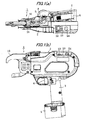
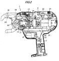
- a reinforcing bar binding machine 1 is shown in Figs. 1(a), 1(b) , and Fig. 2 .
- a grip 3 is extended downward from an outer casing 2
- a trigger lever 4 is provided on a front face of a base part of the grip 3
- a rechargeable battery pack 5 is mounted on a lower end of the grip 3.
- a binding wire reel containing room 6 is provided on a side face of a rear part of the outer casing 2, and a binding wire of a binding wire reel 7 which is loaded in this room 6 is clamped by a binding wire feeding mechanism including a main gear 8 with a V-shaped groove and a driven gear 9 with a V-shaped groove to be fed forward. Then, the binding wire moves forward while being curved along an inner peripheral face of a curved guide nose 10 which is provided on a front part of the outer casing 2. The binding wire is wound around a reinforcing bar by hanging the guide nose 10 on the reinforcing bar.
- a binding wire twisting mechanism 11 is provided in a longitudinal direction inside the outer casing 2.
- the binding wire twisting mechanism 11 is driven to rotate by a motor 13 which is connected to a back end thereof by way of a reduction gear 12.
- a rotation shaft 14 of the binding wire twisting mechanism 11 is threaded, and forms a feed screw mechanism for a sleeve 15 which is fitted over the rotation shaft 14.
- the motor 13 rotates in the normal direction
- the sleeve 15 moves forward, and a pair of hooks 16 which are provided at a front end of the sleeve 15 are closed by a cam mechanism which is not shown, thereby to grasp the binding wire loop.
- the sleeve 15 pushes a lever 17 of a binding wire cutting mechanism.
- the lever 17 is coupled to a rotary cutter 18 which is provided in a distal end part of the guide nose 10, by way of a link 19.
- the rotary cutter 18 is rotatably engaged with a support shaft 20.
- the binding wire is fed to the guide nose 10 through a groove which is formed on the support shaft 20, and then, cut by the rotary cutter 18 when it rotates in association with the lever 17.
- the sleeve 15 which has moved forward passes a rotation stopper (not shown) to be disengaged from rotation restraint, and rotates while grasping the binding wire thereby to twist a binding wire loop, whereby the reinforcing bar is tightened.
- a control circuit board 21 is provided below the binding wire twisting mechanism 11, and as shown in Fig. 1(a) , a power switch 22, a power supply indicator 23, and a torque adjusting dial 24 are provided on an upper face of the outer casing 2 in the back part thereof.
- the torque adjusting dial 24 sets the electric current for controlling the above described reverse rotation of the motor, and can adjust torque at a time of binding (strength of twist), according to a level of the preset value of the electric current. In case where twisting torque is weak, the reinforcing bar is unable to be tightened, and binding strength becomes insufficient. On the other hand, in case where the twisting torque is too strong, the binding wire will be broken by twisting. Therefore, it is necessary to appropriately adjust the torque according to thickness, the number of windings, etc. of the binding wire.
- a CPU (not shown) which is mounted on the control circuit board 21 monitors electric voltage of the rechargeable battery by means of a voltage detecting circuit at every predetermined time. When the electric voltage has dropped to a predetermined voltage value recommended to be recharged, the CPU announces a drop of the voltage by sounding a buzzer.
- the reinforcing bar binding machine 1 has the same mechanical structure as the conventional machine, the invention is characterized in that a control device for preventing stop of the operation of the CPU due to a temporary drop of the electric voltage during the binding operation. Specifically, apart from ordinary monitoring of the electric voltage, the control device monitors the power supply voltage during the twisting operation so that a drop of the voltage below the CPU operation voltage may be avoided, whereby the stop of the operation during the twisting step can be prevented.
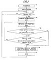
- step 101 the operation proceeds to step 102, in which the machine conducts initialization (a series of motions which includes feeding a predetermined amount of the binding wire, cutting a distal end thereof, aligning the distal end of the binding wire at a position of the rotary cutter 18, and returning the twisting mechanism to a standby position (the initial position)), and rests in a standby state.
- initialization a series of motions which includes feeding a predetermined amount of the binding wire, cutting a distal end thereof, aligning the distal end of the binding wire at a position of the rotary cutter 18, and returning the twisting mechanism to a standby position (the initial position)
- the CPU monitors the voltage of the rechargeable battery by means of the voltage detecting circuit at every predetermined time, apart from this flow chart, and in case where the voltage is lower than a lower limit value of the operation, the CPU announces a drop of the voltage by sounding a buzzer.
- a binding wire twisting step which includes grasping the binding wire by the binding wire twisting mechanism, cutting it by the cutting mechanism, and twisting it by the binding wire twisting mechanism is conducted.
- step 105 the CPU monitors the power supply voltage during the binding wire twisting step, apart from the ordinary monitoring of the voltage as described above, and compares the power supply voltage with a predetermined CPU operation voltage (step 106).
- the load is increased and the electric current is also increased to show a drop of the power supply voltage.
- the machine proceeds to step 108, in which the motor 13 is rotated in the reverse direction to enter into a returning motion from the twisting motion, whereby the twisting mechanism is returned to the initial position and stops there (step 109).
- the voltage of the battery is lower than the lower limit value of the operation when the binding operation starts, it sometimes occurs that the voltage may remarkably drops during the twisting operation due to deterioration of discharging performance of the battery, in case where discharge of the batteryproceeds, or under very cold environment.
- the twisting operation is suspended before the voltage drops below the CPU operation voltage, and the binding wire twisting mechanism is returned to the initial position. Therefore, in case where the power supply voltage has dropped below the predetermined CPU operation voltage during the twisting operation, even though the binding strength which has been preset cannot be obtained, such phenomenon that the binding wire twisting mechanism stops while grasping the binding wires can be avoided. Therefore, such useless troubles as cutting or unwinding the binding wire which is grasped by the binding wire twisting mechanism are not required.
- step 106 the machine proceeds from comparison of the voltages (step 106) to step 107 in which the twisting operation is continued until the actual current value reaches a reference current value for the reverse rotation which has been set by the torque adjusting dial.
- step 108 the ordinary motion of reversely rotating the motor is conducted (step 108), whereby the twisting mechanism is returned to the initial position to stop there (step 109).
- This invention can be applied to a reinforcing bar binding machine, and more particularly, to the reinforcing bar binding machine in which improvement in stability of performance under low temperatures or at a drop of electric voltage is achieved.
Landscapes
- Engineering & Computer Science (AREA)
- Architecture (AREA)
- Mechanical Engineering (AREA)
- Civil Engineering (AREA)
- Structural Engineering (AREA)
- Basic Packing Technique (AREA)
Abstract
Description
- The present invention relates to a reinforcing bar binding machine, and more particularly, to the reinforcing bar binding machine in which improvement in stability of performance under low temperatures and a drop of voltage is achieved.
- A reinforcing bar binding machine which is driven by a motor is provided with a binding wire feeding mechanism for feeding a binding wire to wind it around a reinforcing bar, a binding wire twisting mechanism for grasping and twisting the binding wire wound around the reinforcing bar thereby to strongly tighten the reinforcing bar, and a binding wire cutting mechanism for cutting off a back end of a loop of the binding wire from a following binding wire at the same time when twisting operation of the twisting mechanism starts. In the reinforcing bar binding machine, when an operator pulls a trigger lever, one cycle of operation which includes feeding, cutting and twisting the binding wire is carried out. Structure of this reinforcing bar binding machine is described in many documents, for example, in
Patent Documents - Operation sequence of the reinforcing bar binding machine is controlled by a CPU. When electric current has reached a certain preset value during a twisting step, the CPU judges finish of the twisting step and rotates the motor in a reverse direction to return the twisting mechanism to an initial position, whereby one cycle of the operation is completed.
Patent Document 1:JP-B2-2692495
Patent Document 2:JP-A-2001-038647
Patent Document 3:JP-A-2003-027746
Patent Document 4:JP-A-2003-267307 - A battery driven tool, not confined to the reinforcing bar binding machine, has a problem that mechanical performance such as torque, rotation number and so on may be deteriorated due to deterioration of battery performance under low temperature environment. In the reinforcing bar binding machine, finish of the twisting step is judged by detecting an increase of an electric current value during the twisting step. However, because heavy load is applied in the twisting step for twisting a metallic wire, a power supply voltage remarkably drops, and when discharging performance of the battery is deteriorated under the low temperature environment, the power supply voltage instantaneously drops below an operation voltage of the CPU during the twisting step, and the machine sometimes stops during the twisting operation. In this case, the voltage of the battery is recovered by the stop of the operation whereby the CPU is reset, and when the motor is energized, the voltage drops again. By repeating the stop and reset of the CPU in this manner, one cycle of the operation becomes unable to be completed.
- Binding strength of the reinforcing bar is proportional to the number of windings of the binding wire loop. In case where high binding strength is required such as in case of constructing a bridge or a road where the binding is conducted by increasing the number of windings of the binding wire to four windings, for example, twisting load is also increased. Therefore, there is such anxiety that stops of operation may frequently occur due to a drop of the voltage under low temperature environment.
- One or more embodiments of the invention provide a reinforcing bar binding machine in which operation is stable even under low temperature environment.
- According to one or more embodiments of the invention, a reinforcing bar binding machine is provided with a binding wire feeding mechanism for feeding a binding wire which is wound around a reel to a binding wire guiding nose thereby to form a binding wire loop around a reinforcing bar, and a binding wire twisting mechanism for twisting the binding wire loop which has been formed around the reinforcing bar, by grasping and rotating the binding wire loop, wherein rotation of a driving motor in a normal direction and in a reverse direction is switched by the CPU, whereby one cycle of operation including feeding the binding wire, twisting the binding wire, and returning to the initial position is carried out. The reinforcing bar binding machine is farther provided with a power supply voltage detecting device, a device for comparing the detected voltage with a predetermined CPU operation voltage, and a control device for driving a motor to rotate in the reverse direction, when the voltage has dropped below the predetermined CPU operation voltage, thereby to return the binding wire twisting mechanism to the initial position.
- According to one or more embodiments of the invention, detection of the power supply voltage for controlling the return of the binding wire twisting mechanism to the initial position is carried out only during a binding wire twisting step.
- In the operation of the reinforcing bar binding machine, it is during the binding wire twisting step that the heaviest load is applied and the drop of the voltage is the largest. Therefore, by detecting and comparing the power supply voltage only during the binding wire twisting step, an object of the invention can be achieved and a control routine is simplified.
- In the reinforcing bar binding machine in one or more embodiments of the invention, the power supply voltage during the operation is monitored, and twisting operation is suspended before the voltage drops below the CPU operation voltage, whereby the binding wire twisting mechanism is returned to the initial position. Therefore, it is possible to prevent the binding wire twisting mechanism from being stopped while grasping the binding wire when the CPU stops, and useless troubles such as cutting and unwinding the binding wire which is grasped by the twisting mechanism are not required.
- Other aspects and advantages of the invention will be apparent from the following description and the appended claims.
-
-
Fig. 1 (a) is a plan view of a reinforcing bar binding machine in an exemplary embodiment of the invention. -
Fig. 1(b) is a side view of the reinforcing bar binding machine inFig. 1(a) . -
Fig. 2 is a side view showing an interior of the reinforcing bar binding machine. -
Fig. 3 is a flow chart of operation of the reinforcing bar binding machine. -
- 1
- Reinforcing bar binding machine
- 2
- Outer casing
- 3
- Grip
- 4
- Trigger Lever
- 5
- Rechargeable battery pack
- 7
- Binding wire reel
- 10
- Guide nose
- 11
- Binding wire twisting mechanism
- 13
- Motor
- 15
- Sleeve
- 16
- Hook
- 21
- Control circuit board
- 22
- Power supply switch
- 23
- Power supply indicator
- 24
- Torque adjusting dial
- Now, referring to the drawings, an exemplary embodiment of the invention will be described.
- In
Figs. 1(a), 1(b) , andFig. 2 , a reinforcingbar binding machine 1 is shown. In the reinforcingbar binding machine 1 which has the same mechanical structure as the conventional machine, agrip 3 is extended downward from anouter casing 2, atrigger lever 4 is provided on a front face of a base part of thegrip 3, and a rechargeable battery pack 5 is mounted on a lower end of thegrip 3. - As shown in
Fig. 1(a) , a binding wire reel containing room 6 is provided on a side face of a rear part of theouter casing 2, and a binding wire of abinding wire reel 7 which is loaded in this room 6 is clamped by a binding wire feeding mechanism including a main gear 8 with a V-shaped groove and a drivengear 9 with a V-shaped groove to be fed forward. Then, the binding wire moves forward while being curved along an inner peripheral face of acurved guide nose 10 which is provided on a front part of theouter casing 2. The binding wire is wound around a reinforcing bar by hanging theguide nose 10 on the reinforcing bar. - As shown in
Fig. 2 , a bindingwire twisting mechanism 11 is provided in a longitudinal direction inside theouter casing 2. The bindingwire twisting mechanism 11 is driven to rotate by amotor 13 which is connected to a back end thereof by way of areduction gear 12. Arotation shaft 14 of the bindingwire twisting mechanism 11 is threaded, and forms a feed screw mechanism for asleeve 15 which is fitted over therotation shaft 14. When themotor 13 rotates in the normal direction, thesleeve 15 moves forward, and a pair ofhooks 16 which are provided at a front end of thesleeve 15 are closed by a cam mechanism which is not shown, thereby to grasp the binding wire loop. At the same time, thesleeve 15 pushes alever 17 of a binding wire cutting mechanism. - The
lever 17 is coupled to arotary cutter 18 which is provided in a distal end part of theguide nose 10, by way of alink 19. Therotary cutter 18 is rotatably engaged with asupport shaft 20. The binding wire is fed to theguide nose 10 through a groove which is formed on thesupport shaft 20, and then, cut by therotary cutter 18 when it rotates in association with thelever 17. Thesleeve 15 which has moved forward passes a rotation stopper (not shown) to be disengaged from rotation restraint, and rotates while grasping the binding wire thereby to twist a binding wire loop, whereby the reinforcing bar is tightened. - While twisting of the binding wire proceeds, a twisting load is increased, and electric current which is flowing into the
motor 13 is also increased. When the electric current has reached a preset value, a control part rotates themotor 13 in the reverse direction. With the reverse rotation of the motor, thesleeve 15 of the bindingwire twisting mechanism 11 moves backward, and thehooks 16 at the front end thereof are opened to release the binding wire. Then, thesleeve 15 returns to an initial position to stop there. The above described is one cycle of the reinforcing bar binding operation. By once pulling thetrigger lever 4, one cycle of the operation is instantaneously carried out. - As shown in
Fig. 2 , acontrol circuit board 21 is provided below the bindingwire twisting mechanism 11, and as shown inFig. 1(a) , apower switch 22, apower supply indicator 23, and atorque adjusting dial 24 are provided on an upper face of theouter casing 2 in the back part thereof. Thetorque adjusting dial 24 sets the electric current for controlling the above described reverse rotation of the motor, and can adjust torque at a time of binding (strength of twist), according to a level of the preset value of the electric current. In case where twisting torque is weak, the reinforcing bar is unable to be tightened, and binding strength becomes insufficient. On the other hand, in case where the twisting torque is too strong, the binding wire will be broken by twisting. Therefore, it is necessary to appropriately adjust the torque according to thickness, the number of windings, etc. of the binding wire. - A CPU (not shown) which is mounted on the
control circuit board 21 monitors electric voltage of the rechargeable battery by means of a voltage detecting circuit at every predetermined time. When the electric voltage has dropped to a predetermined voltage value recommended to be recharged, the CPU announces a drop of the voltage by sounding a buzzer. - Although the reinforcing
bar binding machine 1 according to the invention has the same mechanical structure as the conventional machine, the invention is characterized in that a control device for preventing stop of the operation of the CPU due to a temporary drop of the electric voltage during the binding operation. Specifically, apart from ordinary monitoring of the electric voltage, the control device monitors the power supply voltage during the twisting operation so that a drop of the voltage below the CPU operation voltage may be avoided, whereby the stop of the operation during the twisting step can be prevented. - Now, referring to
Fig. 3 , operation of the reinforcingbar binding machine 1 will be described. When the power supply is turned on (step 101), the operation proceeds to step 102, in which the machine conducts initialization (a series of motions which includes feeding a predetermined amount of the binding wire, cutting a distal end thereof, aligning the distal end of the binding wire at a position of therotary cutter 18, and returning the twisting mechanism to a standby position (the initial position)), and rests in a standby state. - As described above, the CPU monitors the voltage of the rechargeable battery by means of the voltage detecting circuit at every predetermined time, apart from this flow chart, and in case where the voltage is lower than a lower limit value of the operation, the CPU announces a drop of the voltage by sounding a buzzer.
- In case where the voltage is higher than the lower limit value of the operation, by once pulling the trigger lever (step 103), the binding wire feeding mechanism is driven to feed the binding wire (step 104), and then, a binding wire twisting step (step 105) which includes grasping the binding wire by the binding wire twisting mechanism, cutting it by the cutting mechanism, and twisting it by the binding wire twisting mechanism is conducted.
- In step 105, the CPU monitors the power supply voltage during the binding wire twisting step, apart from the ordinary monitoring of the voltage as described above, and compares the power supply voltage with a predetermined CPU operation voltage (step 106). As the twisting of the binding wire proceeds, the load is increased and the electric current is also increased to show a drop of the power supply voltage. At a moment when the power supply voltage drops to the lower limit of the predetermined CPU operation voltage, the machine proceeds to step 108, in which the
motor 13 is rotated in the reverse direction to enter into a returning motion from the twisting motion, whereby the twisting mechanism is returned to the initial position and stops there (step 109). - Although the voltage of the battery is lower than the lower limit value of the operation when the binding operation starts, it sometimes occurs that the voltage may remarkably drops during the twisting operation due to deterioration of discharging performance of the battery, in case where discharge of the batteryproceeds, or under very cold environment. However, according to the invention, the twisting operation is suspended before the voltage drops below the CPU operation voltage, and the binding wire twisting mechanism is returned to the initial position. Therefore, in case where the power supply voltage has dropped below the predetermined CPU operation voltage during the twisting operation, even though the binding strength which has been preset cannot be obtained, such phenomenon that the binding wire twisting mechanism stops while grasping the binding wires can be avoided. Therefore, such useless troubles as cutting or unwinding the binding wire which is grasped by the binding wire twisting mechanism are not required.
- When the discharging performance of the battery is sufficient, and the drop of the voltage is small in such a case that the outside temperature is not extremely low, the machine proceeds from comparison of the voltages (step 106) to step 107 in which the twisting operation is continued until the actual current value reaches a reference current value for the reverse rotation which has been set by the torque adjusting dial. When the current value is increased up to the preset value, the ordinary motion of reversely rotating the motor is conducted (step 108), whereby the twisting mechanism is returned to the initial position to stop there (step 109).
- It is apparent that this invention is not limited to the above described embodiment, but various modifications can be made within a technical scope of the invention, and the modified embodiments also belong to the invention.
- This application is based on
Japanese Patent Application (ApplicationNo. 2005-194206) filed on July 1, 2005 - This invention can be applied to a reinforcing bar binding machine, and more particularly, to the reinforcing bar binding machine in which improvement in stability of performance under low temperatures or at a drop of electric voltage is achieved.
Claims (3)
- A reinforcing bar binding machine comprising:a binding wire feeding mechanism that feeds a binding wire which is wound around a reel to a binding wire guiding nose and forms a binding wire loop around a reinforcing bar;a binding wire twisting mechanism that twists the binding wire loop formed around the reinforcing bar, by grasping and rotating the binding wire loop;a CPU;a power supply voltage detecting device;a device for comparing the detected voltage with a predetermined CPU operation voltage, anda control device that drives a motor in a reverse direction, when the voltage has dropped below the predetermined CPU operation voltage, thereby to return the binding wire twisting mechanism to an initial position.
- The reinforcing bar binding machine according to claim 1, wherein rotation of a driving motor in a normal direction and in the reverse direction is switched by the CPU, whereby one cycle of operation including feeding the binding wire, twisting the binding wire, and returning the binding wire twisting mechanism to the initial position is carried out.
- The reinforcing bar binding machine according to claim 1, wherein the detection of the power supply voltage for controlling the return of the binding wire twisting mechanism to the initial position is carried out only during a binding wire twisting step.
Applications Claiming Priority (2)
| Application Number | Priority Date | Filing Date | Title |
|---|---|---|---|
| JP2005194206A JP4710438B2 (en) | 2005-07-01 | 2005-07-01 | Rebar binding machine |
| PCT/JP2006/312918 WO2007004491A1 (en) | 2005-07-01 | 2006-06-28 | Reinforcing bar binding machine |
Publications (3)
| Publication Number | Publication Date |
|---|---|
| EP1900640A1 true EP1900640A1 (en) | 2008-03-19 |
| EP1900640A4 EP1900640A4 (en) | 2012-03-21 |
| EP1900640B1 EP1900640B1 (en) | 2016-03-09 |
Family
ID=37604360
Family Applications (1)
| Application Number | Title | Priority Date | Filing Date |
|---|---|---|---|
| EP06767535.5A Active EP1900640B1 (en) | 2005-07-01 | 2006-06-28 | Reinforcing bar binding machine |
Country Status (11)
| Country | Link |
|---|---|
| US (2) | US9004114B2 (en) |
| EP (1) | EP1900640B1 (en) |
| JP (1) | JP4710438B2 (en) |
| KR (1) | KR101278315B1 (en) |
| CN (1) | CN101213132B (en) |
| AU (1) | AU2006266904B2 (en) |
| CA (1) | CA2612609C (en) |
| DK (1) | DK1900640T3 (en) |
| IL (1) | IL188224A (en) |
| TW (1) | TW200714519A (en) |
| WO (1) | WO2007004491A1 (en) |
Cited By (2)
| Publication number | Priority date | Publication date | Assignee | Title |
|---|---|---|---|---|
| EP2123847A3 (en) * | 2008-05-19 | 2010-04-14 | Max Co., Ltd. | Brake system of wire reel in reinforcing bar binding machine |
| EP3527746A1 (en) * | 2018-02-16 | 2019-08-21 | Max Co., Ltd. | Binding machine |
Families Citing this family (32)
| Publication number | Priority date | Publication date | Assignee | Title |
|---|---|---|---|---|
| JP4710438B2 (en) * | 2005-07-01 | 2011-06-29 | マックス株式会社 | Rebar binding machine |
| TWI650193B (en) * | 2008-05-19 | 2019-02-11 | 日商美克司股份有限公司 | Reinforcing bar binding machine |
| JP5217621B2 (en) * | 2008-05-19 | 2013-06-19 | マックス株式会社 | Wiring structure in reinforcing bar binding machine |
| TWD136590S1 (en) * | 2009-04-14 | 2010-08-21 | 美克司股份有限公司 | Rebar tying machine |
| JP5896592B2 (en) * | 2010-03-19 | 2016-03-30 | ストラパック株式会社 | Packing equipment |
| JP6417772B2 (en) * | 2014-07-31 | 2018-11-07 | マックス株式会社 | Rebar binding machine |
| KR102130394B1 (en) * | 2015-07-22 | 2020-07-06 | 마크스 가부시기가이샤 | Binding machine |
| JP2017089271A (en) * | 2015-11-11 | 2017-05-25 | 株式会社マキタ | Binding machine |
| JP6674265B2 (en) * | 2016-01-28 | 2020-04-01 | 株式会社マキタ | Rebar binding machine |
| JP6698425B2 (en) * | 2016-05-20 | 2020-05-27 | 株式会社マキタ | Rebar binding machine |
| DE102017209040A1 (en) | 2016-08-09 | 2018-02-15 | Robert Bosch Gmbh | Method for calibrating and / or operating a handheld power tool and handheld power tool |
| JP6922221B2 (en) | 2016-12-29 | 2021-08-18 | マックス株式会社 | Cable ties |
| CN106644551B (en) * | 2017-02-22 | 2023-06-16 | 广东顺德华焱电子科技有限公司 | Service life testing device of reinforcing steel bar binding machine |
| US11365552B2 (en) | 2017-06-07 | 2022-06-21 | Max Co., Ltd. | Binding machine |
| JP6985928B2 (en) * | 2017-12-27 | 2021-12-22 | 株式会社マキタ | Cable ties |
| USD935867S1 (en) * | 2018-12-13 | 2021-11-16 | Pellenc | Vine tying machine |
| USD935866S1 (en) * | 2018-12-13 | 2021-11-16 | Pellenc | Vine tying machine |
| EP4545732A3 (en) | 2019-03-11 | 2025-05-07 | Max Co., Ltd. | Binding machine |
| JP7293880B2 (en) * | 2019-06-03 | 2023-06-20 | マックス株式会社 | binding machine |
| CN109930838B (en) * | 2019-04-23 | 2021-02-26 | 车建民 | Reinforcing steel bar binding machine |
| US11548089B2 (en) | 2019-08-15 | 2023-01-10 | Forney Industries, Inc. | Wire spool gun |
| USD939939S1 (en) * | 2019-11-08 | 2022-01-04 | Forney Industries, Inc. | Wire spool gun |
| USD939940S1 (en) * | 2019-11-08 | 2022-01-04 | Forney Industries, Inc. | Wire spool gun |
| US11529669B2 (en) | 2019-12-17 | 2022-12-20 | Makita Corporation | Rebar tying tool |
| JP7427994B2 (en) * | 2020-02-10 | 2024-02-06 | マックス株式会社 | Binding machine |
| USD1042068S1 (en) * | 2021-05-19 | 2024-09-17 | Gustav Klauke Gmbh | Hydraulic press tool |
| CN113942703B (en) * | 2021-09-18 | 2023-03-21 | 台州市新大陆电子科技有限公司 | Information processing method of binding machine |
| JP2023152250A (en) | 2022-04-01 | 2023-10-16 | 株式会社マキタ | Rebar binding machine |
| CN115653316B (en) * | 2022-11-15 | 2023-03-31 | 中铁九局集团有限公司 | Reinforcing mesh binding robot and binding method thereof |
| JP1768705S (en) * | 2023-06-13 | 2024-04-22 | Rebar Tying Machine | |
| JP1766305S (en) * | 2023-06-13 | 2024-03-25 | Rebar binding machine body | |
| USD1088826S1 (en) * | 2023-07-27 | 2025-08-19 | Shenzhen Unitweld Welding and Motor Co., Ltd. | Wire spool gun |
Family Cites Families (15)
| Publication number | Priority date | Publication date | Assignee | Title |
|---|---|---|---|---|
| JP2917597B2 (en) * | 1991-06-29 | 1999-07-12 | いすゞ自動車株式会社 | Insulated piston |
| JP2502936Y2 (en) * | 1991-07-24 | 1996-06-26 | マックス株式会社 | Power switch controller for binding machine |
| JP2692495B2 (en) * | 1992-05-21 | 1997-12-17 | マックス株式会社 | One-cycle control device for binding machine |
| JP2935629B2 (en) * | 1993-10-05 | 1999-08-16 | 株式会社共立 | Packing machine |
| US5553478A (en) * | 1994-04-08 | 1996-09-10 | Burndy Corporation | Hand-held compression tool |
| JPH09156608A (en) * | 1995-12-06 | 1997-06-17 | Bentatsuku:Kk | Method and device for controlling binding machine |
| JP3227693B2 (en) * | 1996-08-02 | 2001-11-12 | マックス株式会社 | Prevention method of wire breakage in rebar tying machine |
| DE19818755A1 (en) * | 1998-04-27 | 1999-11-04 | Honsel M H Beteiligungs Gmbh | Rivet setting tool |
| JP3582411B2 (en) | 1999-07-23 | 2004-10-27 | マックス株式会社 | Rebar binding machine |
| JP3859916B2 (en) * | 1999-11-26 | 2006-12-20 | カルソニックカンセイ株式会社 | Circuit equipment |
| JP4747452B2 (en) * | 2001-07-19 | 2011-08-17 | マックス株式会社 | Rebar binding machine |
| AU2002335474B2 (en) * | 2001-09-28 | 2007-08-30 | Max Kabushiki Kaisha | Reinforcement binding machine, reel, and method of detecting rotation of reel |
| CN1258410C (en) * | 2001-09-28 | 2006-06-07 | 美克司株式会社 | Rebar binding machine and reel for the machine |
| JP3680804B2 (en) | 2002-03-12 | 2005-08-10 | マックス株式会社 | Rebar binding machine |
| JP4710438B2 (en) * | 2005-07-01 | 2011-06-29 | マックス株式会社 | Rebar binding machine |
-
2005
- 2005-07-01 JP JP2005194206A patent/JP4710438B2/en not_active Expired - Fee Related
-
2006
- 2006-06-28 DK DK06767535.5T patent/DK1900640T3/en active
- 2006-06-28 WO PCT/JP2006/312918 patent/WO2007004491A1/en not_active Ceased
- 2006-06-28 TW TW095123297A patent/TW200714519A/en not_active IP Right Cessation
- 2006-06-28 CA CA2612609A patent/CA2612609C/en active Active
- 2006-06-28 CN CN2006800240047A patent/CN101213132B/en active Active
- 2006-06-28 KR KR1020077030648A patent/KR101278315B1/en active Active
- 2006-06-28 US US11/994,261 patent/US9004114B2/en active Active
- 2006-06-28 EP EP06767535.5A patent/EP1900640B1/en active Active
- 2006-06-28 AU AU2006266904A patent/AU2006266904B2/en active Active
-
2007
- 2007-12-18 IL IL188224A patent/IL188224A/en active IP Right Grant
-
2015
- 2015-03-06 US US14/640,910 patent/US9453352B2/en active Active
Cited By (14)
| Publication number | Priority date | Publication date | Assignee | Title |
|---|---|---|---|---|
| US9399875B2 (en) | 2008-05-19 | 2016-07-26 | Max Co., Ltd | Brake system of wire reel in reinforcing bar binding machine |
| US9856041B2 (en) | 2008-05-19 | 2018-01-02 | Max Co., Ltd. | Brake system of wire reel in reinforcing bar binding machine |
| US9132472B2 (en) | 2008-05-19 | 2015-09-15 | Max Co., Ltd. | Brake system of wire reel in reinforcing bar binding machine |
| US9192979B2 (en) | 2008-05-19 | 2015-11-24 | Max Co., Ltd. | Brake system of wire reel in reinforcing bar binding machine |
| US9221566B2 (en) | 2008-05-19 | 2015-12-29 | Max Co., Ltd. | Brake system of wire reel in reinforcing bar binding machine |
| US9308572B2 (en) | 2008-05-19 | 2016-04-12 | Max Co., Ltd. | Brake system of wire reel in reinforcing bar binding machine |
| US10167095B2 (en) | 2008-05-19 | 2019-01-01 | Max Co., Ltd. | Brake system of wire reel in reinforcing bar binding machine |
| EP2123847A3 (en) * | 2008-05-19 | 2010-04-14 | Max Co., Ltd. | Brake system of wire reel in reinforcing bar binding machine |
| EP2757211A1 (en) * | 2008-05-19 | 2014-07-23 | Max Co., Ltd. | Brake system of wire reel in reinforcing bar binding machine |
| EP3483360A1 (en) * | 2008-05-19 | 2019-05-15 | Max Co., Ltd. | Brake system of wire reel in reinforcing bar binding machine |
| US11780621B2 (en) | 2008-05-19 | 2023-10-10 | Max Co., Ltd. | Brake system of wire reel in reinforcing bar binding machine |
| US10457428B2 (en) | 2008-05-19 | 2019-10-29 | Max Co., Ltd. | Brake system of wire reel in reinforcing bar binding machine |
| US11486155B2 (en) | 2018-02-16 | 2022-11-01 | Max Co., Ltd. | Binding machine |
| EP3527746A1 (en) * | 2018-02-16 | 2019-08-21 | Max Co., Ltd. | Binding machine |
Also Published As
| Publication number | Publication date |
|---|---|
| KR20080021076A (en) | 2008-03-06 |
| JP4710438B2 (en) | 2011-06-29 |
| CN101213132A (en) | 2008-07-02 |
| IL188224A (en) | 2011-09-27 |
| EP1900640B1 (en) | 2016-03-09 |
| US20090090428A1 (en) | 2009-04-09 |
| AU2006266904B2 (en) | 2011-05-26 |
| CA2612609A1 (en) | 2007-01-11 |
| DK1900640T3 (en) | 2016-05-23 |
| AU2006266904A1 (en) | 2007-01-11 |
| WO2007004491A1 (en) | 2007-01-11 |
| US9004114B2 (en) | 2015-04-14 |
| CA2612609C (en) | 2013-05-28 |
| US9453352B2 (en) | 2016-09-27 |
| TWI358377B (en) | 2012-02-21 |
| KR101278315B1 (en) | 2013-06-25 |
| TW200714519A (en) | 2007-04-16 |
| JP2007008562A (en) | 2007-01-18 |
| US20150176295A1 (en) | 2015-06-25 |
| EP1900640A4 (en) | 2012-03-21 |
| CN101213132B (en) | 2011-09-28 |
| IL188224A0 (en) | 2008-03-20 |
Similar Documents
| Publication | Publication Date | Title |
|---|---|---|
| EP1900640B1 (en) | Reinforcing bar binding machine | |
| US7140400B2 (en) | Reinforcing bar-binding machine | |
| EP0822304B1 (en) | Method of preventing wire from being twisted off in reinforcing bar fastening machine | |
| US11485528B2 (en) | Device for fitting cable ties | |
| CN107849857B (en) | Reinforcing steel bar binding device | |
| EP1837279B1 (en) | Reinforcement binder | |
| KR20160060615A (en) | Brake system of wire reel in reinforcing bar binding machine | |
| EP0822303A1 (en) | Method of preventing wire from becoming entangled in reinforcing bar fastening machine | |
| JP4144473B2 (en) | Rebar binding machine cooling device | |
| WO2006077744A1 (en) | Reinforcing rod binding machine | |
| JP5045549B2 (en) | Brake device for wire reel in rebar binding machine and brake processing method thereof | |
| JP2006192518A (en) | Charging type electric tool | |
| JP3598786B2 (en) | Prevention method of wire breakage in rebar tying machine | |
| CN113942703A (en) | Information processing method of binding machine | |
| JP2005127134A (en) | Reinforcement binder | |
| JP2005210963A (en) | Fishing electric reel |
Legal Events
| Date | Code | Title | Description |
|---|---|---|---|
| PUAI | Public reference made under article 153(3) epc to a published international application that has entered the european phase |
Free format text: ORIGINAL CODE: 0009012 |
|
| 17P | Request for examination filed |
Effective date: 20071214 |
|
| AK | Designated contracting states |
Kind code of ref document: A1 Designated state(s): AT BE BG CH CY CZ DE DK EE ES FI FR GB GR HU IE IS IT LI LT LU LV MC NL PL PT RO SE SI SK TR |
|
| DAX | Request for extension of the european patent (deleted) | ||
| DAX | Request for extension of the european patent (deleted) | ||
| A4 | Supplementary search report drawn up and despatched |
Effective date: 20120216 |
|
| RIC1 | Information provided on ipc code assigned before grant |
Ipc: E04G 21/12 20060101ALI20120210BHEP Ipc: B65B 13/28 20060101ALI20120210BHEP Ipc: B65B 13/18 20060101AFI20120210BHEP |
|
| GRAP | Despatch of communication of intention to grant a patent |
Free format text: ORIGINAL CODE: EPIDOSNIGR1 |
|
| INTG | Intention to grant announced |
Effective date: 20150908 |
|
| GRAS | Grant fee paid |
Free format text: ORIGINAL CODE: EPIDOSNIGR3 |
|
| GRAA | (expected) grant |
Free format text: ORIGINAL CODE: 0009210 |
|
| RIN1 | Information on inventor provided before grant (corrected) |
Inventor name: MATSUOKA, ATSUSHI Inventor name: KASAHARA, AKIRA |
|
| AK | Designated contracting states |
Kind code of ref document: B1 Designated state(s): AT BE BG CH CY CZ DE DK EE ES FI FR GB GR HU IE IS IT LI LT LU LV MC NL PL PT RO SE SI SK TR |
|
| REG | Reference to a national code |
Ref country code: GB Ref legal event code: FG4D |
|
| REG | Reference to a national code |
Ref country code: AT Ref legal event code: REF Ref document number: 779282 Country of ref document: AT Kind code of ref document: T Effective date: 20160315 Ref country code: CH Ref legal event code: EP |
|
| REG | Reference to a national code |
Ref country code: IE Ref legal event code: FG4D |
|
| REG | Reference to a national code |
Ref country code: DE Ref legal event code: R096 Ref document number: 602006048166 Country of ref document: DE |
|
| REG | Reference to a national code |
Ref country code: SE Ref legal event code: TRGR |
|
| REG | Reference to a national code |
Ref country code: DK Ref legal event code: T3 Effective date: 20160517 |
|
| REG | Reference to a national code |
Ref country code: NL Ref legal event code: FP |
|
| REG | Reference to a national code |
Ref country code: FR Ref legal event code: PLFP Year of fee payment: 11 |
|
| REG | Reference to a national code |
Ref country code: LT Ref legal event code: MG4D |
|
| PG25 | Lapsed in a contracting state [announced via postgrant information from national office to epo] |
Ref country code: FI Free format text: LAPSE BECAUSE OF FAILURE TO SUBMIT A TRANSLATION OF THE DESCRIPTION OR TO PAY THE FEE WITHIN THE PRESCRIBED TIME-LIMIT Effective date: 20160309 Ref country code: ES Free format text: LAPSE BECAUSE OF FAILURE TO SUBMIT A TRANSLATION OF THE DESCRIPTION OR TO PAY THE FEE WITHIN THE PRESCRIBED TIME-LIMIT Effective date: 20160309 Ref country code: GR Free format text: LAPSE BECAUSE OF FAILURE TO SUBMIT A TRANSLATION OF THE DESCRIPTION OR TO PAY THE FEE WITHIN THE PRESCRIBED TIME-LIMIT Effective date: 20160610 |
|
| REG | Reference to a national code |
Ref country code: AT Ref legal event code: MK05 Ref document number: 779282 Country of ref document: AT Kind code of ref document: T Effective date: 20160309 |
|
| PG25 | Lapsed in a contracting state [announced via postgrant information from national office to epo] |
Ref country code: LV Free format text: LAPSE BECAUSE OF FAILURE TO SUBMIT A TRANSLATION OF THE DESCRIPTION OR TO PAY THE FEE WITHIN THE PRESCRIBED TIME-LIMIT Effective date: 20160309 Ref country code: LT Free format text: LAPSE BECAUSE OF FAILURE TO SUBMIT A TRANSLATION OF THE DESCRIPTION OR TO PAY THE FEE WITHIN THE PRESCRIBED TIME-LIMIT Effective date: 20160309 Ref country code: PL Free format text: LAPSE BECAUSE OF FAILURE TO SUBMIT A TRANSLATION OF THE DESCRIPTION OR TO PAY THE FEE WITHIN THE PRESCRIBED TIME-LIMIT Effective date: 20160309 |
|
| PG25 | Lapsed in a contracting state [announced via postgrant information from national office to epo] |
Ref country code: IS Free format text: LAPSE BECAUSE OF FAILURE TO SUBMIT A TRANSLATION OF THE DESCRIPTION OR TO PAY THE FEE WITHIN THE PRESCRIBED TIME-LIMIT Effective date: 20160709 Ref country code: EE Free format text: LAPSE BECAUSE OF FAILURE TO SUBMIT A TRANSLATION OF THE DESCRIPTION OR TO PAY THE FEE WITHIN THE PRESCRIBED TIME-LIMIT Effective date: 20160309 |
|
| PG25 | Lapsed in a contracting state [announced via postgrant information from national office to epo] |
Ref country code: SK Free format text: LAPSE BECAUSE OF FAILURE TO SUBMIT A TRANSLATION OF THE DESCRIPTION OR TO PAY THE FEE WITHIN THE PRESCRIBED TIME-LIMIT Effective date: 20160309 Ref country code: PT Free format text: LAPSE BECAUSE OF FAILURE TO SUBMIT A TRANSLATION OF THE DESCRIPTION OR TO PAY THE FEE WITHIN THE PRESCRIBED TIME-LIMIT Effective date: 20160711 Ref country code: CZ Free format text: LAPSE BECAUSE OF FAILURE TO SUBMIT A TRANSLATION OF THE DESCRIPTION OR TO PAY THE FEE WITHIN THE PRESCRIBED TIME-LIMIT Effective date: 20160309 Ref country code: AT Free format text: LAPSE BECAUSE OF FAILURE TO SUBMIT A TRANSLATION OF THE DESCRIPTION OR TO PAY THE FEE WITHIN THE PRESCRIBED TIME-LIMIT Effective date: 20160309 Ref country code: RO Free format text: LAPSE BECAUSE OF FAILURE TO SUBMIT A TRANSLATION OF THE DESCRIPTION OR TO PAY THE FEE WITHIN THE PRESCRIBED TIME-LIMIT Effective date: 20160309 |
|
| REG | Reference to a national code |
Ref country code: DE Ref legal event code: R097 Ref document number: 602006048166 Country of ref document: DE |
|
| PG25 | Lapsed in a contracting state [announced via postgrant information from national office to epo] |
Ref country code: IT Free format text: LAPSE BECAUSE OF FAILURE TO SUBMIT A TRANSLATION OF THE DESCRIPTION OR TO PAY THE FEE WITHIN THE PRESCRIBED TIME-LIMIT Effective date: 20160309 Ref country code: BE Free format text: LAPSE BECAUSE OF FAILURE TO SUBMIT A TRANSLATION OF THE DESCRIPTION OR TO PAY THE FEE WITHIN THE PRESCRIBED TIME-LIMIT Effective date: 20160309 |
|
| PLBE | No opposition filed within time limit |
Free format text: ORIGINAL CODE: 0009261 |
|
| STAA | Information on the status of an ep patent application or granted ep patent |
Free format text: STATUS: NO OPPOSITION FILED WITHIN TIME LIMIT |
|
| PG25 | Lapsed in a contracting state [announced via postgrant information from national office to epo] |
Ref country code: MC Free format text: LAPSE BECAUSE OF FAILURE TO SUBMIT A TRANSLATION OF THE DESCRIPTION OR TO PAY THE FEE WITHIN THE PRESCRIBED TIME-LIMIT Effective date: 20160309 |
|
| REG | Reference to a national code |
Ref country code: CH Ref legal event code: PL |
|
| 26N | No opposition filed |
Effective date: 20161212 |
|
| PG25 | Lapsed in a contracting state [announced via postgrant information from national office to epo] |
Ref country code: BG Free format text: LAPSE BECAUSE OF FAILURE TO SUBMIT A TRANSLATION OF THE DESCRIPTION OR TO PAY THE FEE WITHIN THE PRESCRIBED TIME-LIMIT Effective date: 20160609 |
|
| REG | Reference to a national code |
Ref country code: IE Ref legal event code: MM4A |
|
| PG25 | Lapsed in a contracting state [announced via postgrant information from national office to epo] |
Ref country code: LI Free format text: LAPSE BECAUSE OF NON-PAYMENT OF DUE FEES Effective date: 20160630 Ref country code: CH Free format text: LAPSE BECAUSE OF NON-PAYMENT OF DUE FEES Effective date: 20160630 |
|
| REG | Reference to a national code |
Ref country code: FR Ref legal event code: PLFP Year of fee payment: 12 |
|
| PG25 | Lapsed in a contracting state [announced via postgrant information from national office to epo] |
Ref country code: SI Free format text: LAPSE BECAUSE OF FAILURE TO SUBMIT A TRANSLATION OF THE DESCRIPTION OR TO PAY THE FEE WITHIN THE PRESCRIBED TIME-LIMIT Effective date: 20160309 Ref country code: IE Free format text: LAPSE BECAUSE OF NON-PAYMENT OF DUE FEES Effective date: 20160628 |
|
| REG | Reference to a national code |
Ref country code: FR Ref legal event code: PLFP Year of fee payment: 13 |
|
| PG25 | Lapsed in a contracting state [announced via postgrant information from national office to epo] |
Ref country code: HU Free format text: LAPSE BECAUSE OF FAILURE TO SUBMIT A TRANSLATION OF THE DESCRIPTION OR TO PAY THE FEE WITHIN THE PRESCRIBED TIME-LIMIT; INVALID AB INITIO Effective date: 20060628 Ref country code: CY Free format text: LAPSE BECAUSE OF FAILURE TO SUBMIT A TRANSLATION OF THE DESCRIPTION OR TO PAY THE FEE WITHIN THE PRESCRIBED TIME-LIMIT Effective date: 20160309 |
|
| PG25 | Lapsed in a contracting state [announced via postgrant information from national office to epo] |
Ref country code: TR Free format text: LAPSE BECAUSE OF FAILURE TO SUBMIT A TRANSLATION OF THE DESCRIPTION OR TO PAY THE FEE WITHIN THE PRESCRIBED TIME-LIMIT Effective date: 20160309 Ref country code: LU Free format text: LAPSE BECAUSE OF NON-PAYMENT OF DUE FEES Effective date: 20160628 |
|
| PGFP | Annual fee paid to national office [announced via postgrant information from national office to epo] |
Ref country code: NL Payment date: 20250516 Year of fee payment: 20 |
|
| PGFP | Annual fee paid to national office [announced via postgrant information from national office to epo] |
Ref country code: DE Payment date: 20250507 Year of fee payment: 20 |
|
| PGFP | Annual fee paid to national office [announced via postgrant information from national office to epo] |
Ref country code: DK Payment date: 20250618 Year of fee payment: 20 Ref country code: GB Payment date: 20250508 Year of fee payment: 20 |
|
| PGFP | Annual fee paid to national office [announced via postgrant information from national office to epo] |
Ref country code: FR Payment date: 20250508 Year of fee payment: 20 |
|
| PGFP | Annual fee paid to national office [announced via postgrant information from national office to epo] |
Ref country code: SE Payment date: 20250514 Year of fee payment: 20 |